iclass Reader (RevA) PIC 18F452/18F6621 RAM Dumper Operating Instructions
|
|
|
- Kory Crawford
- 5 years ago
- Views:
Transcription

1 iclass Reader (RevA) PIC 18F452/18F6621 RAM Dumper Operating Instructions Proxclone.com Revision 2.0 December2015
 are generated from a dc-dc booster circuit that is fed from the +5Vdc USB power input.")
2 Overview The RAM dumper circuit is used in conjunction with a HID iclass RevA reader to dump the contents of the PIC microcontroller RAM memory. The circuit is powered from a standard PC USB port. All of the required voltages (including the Vpp programming signal) are generated from a dc-dc booster circuit that is fed from the +5Vdc USB power input. The extracted RAM data is output on a serial UART interface that is fed into a UART-to-USB adapter that appears as a virtual COM port interface on the PC. Data is captured using any standard serial terminal software (e.g. CoolTerm or Hyperterminal) which is capable of accepting a serial ascii data stream. A photo of the RAM Dumper circuit board layout is shown in Figure 1 below. Setup The PL2303 UART-to-USB driver software can be downloaded from the following website: The terminal software that is being used should be setup to receive serial data as 19200,8,N,1. Figure 1. RAM Dumper Circuit Board Layout
3 Operation 1. Ensure that the PL2303 Driver software has been properly installed before proceeding to step Attach the PIC ICSP Debug interface cable between the RAM Dumper unit and the iclass reader target hardware. Note that the ICSP debug interface signals on the iclass readers are NOT always arranged the same. A connection to an R40 reader is depicted in Figure 2. R30/R40/RW300/RW400/RK40/RKW400 Pinout is as follows: Pin 1 Vss/Gnd (leftmost pin looking at backside of reader) Pin 2 Vdd (not used) Pin 3 Vpp Pin 4 PGD/Data Pin 5 PGC/Clock Pin 6 Aux (not used) R90 Reader Pinout is as follows: Pin 1 Vpp (pin nearest tamper switch) Pin 2 Vss/Gnd Pin 3 Vdd (not used) Pin 4 PGC/Clk Pin 5 PGD/Data 3. Attach a separate power source (5-16Vdc nominal) to the iclass Reader. Power up the reader and verify that the reader plays its startup tune signifying that the reader is operational and that the factory default firmware is currently loaded. 4. Place an iclass credential near the reader. This will ensure that the HID Global Master keys are loaded into RAM from the PIC s EEPROM memory. 5. Position the PIC chip selector switch Up for a PIC18F452 device or Down for a PIC18F6621 device. This switch defines the size of the RAM file that is to be dumped. 6. Plug the RAM Dumper USB interface into a PC USB port. (note in Windows Device Manager the COM port that has been assigned) 7. Turn on the RAM Dumper Main Power Switch (Up position). The blue LED will illuminate to indicate that the microcontroller has been initialized and proper voltage levels are being generated. 8. Bring up the terminal software(e.g. CoolTerm,HyperTerminal) being used to capture the dumped RAM data. This software must be setup to receive data using the following UART parameters: COM-TBD,19200,8,N,1. 9. Position the Debug Mode switch in the up/on position. This will apply the Vpp programming voltage to the PIC chip, placing it into a debug mode of operation. 10. Press and release the Dump pushbutton switch. The LED will blink 8 times and then turn off while the serial ascii data is being transferred. The LED will turn on again once the entire contents of the RAM have been transferred (approx sec)
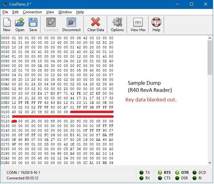
 Example RAM Dump The captured data shown in the screenshot below is an actual dump obtained from an iclass R40 reader using the CoolTerm")
4 11. Position the Debug Mode switch in the down/off position to exit debug mode. 12. Turn off the RAM Dumper Main Power switch. Figure 2. ICSP Connection to R40 Reader (Black Vss/Gnd on outside pin) Example RAM Dump The captured data shown in the screenshot below is an actual dump obtained from an iclass R40 reader using the CoolTerm Terminal application program. [Note: Sensitive authentication key and encryption key information has been obscured]. The freeware version of CoolTerm can be found here: The PIC RAM data that is outputted has been pre-formatted to simplify its readability. The leftmost column is the RAM address. All data is dumped as ASCII hex bytes.
5
iclass Cloner Operating Instructions
 Hardware Setup The iclass Cloner application operates in conjunction with an off-the-shelf iclass Reader Writer manufactured by HID Corporation. Communication with the reader is via the iclass readers
Portable iclass Cloner Operating Instructions
 Overview The portable iclass cloner/programmer circuit is comprised of a commercial HID RW100 iclass Reader/Writer unit operating in conjunction with a customized embedded microcontroller/display unit.
PIC Dev 14 Surface Mount PCB Assembly and Test Lab 1
 Name Lab Day Lab Time PIC Dev 14 Surface Mount PCB Assembly and Test Lab 1 Introduction: The Pic Dev 14 SMD is a simple 8-bit Microchip Pic microcontroller breakout board for learning and experimenting
Operating Instructions Wiegand Decoder with SD Card
 Overview The wiegand decoder assembly is comprised of a custom embedded microcontroller circuit and display unit along with an optional removable memory card. The unit interfaces with most RFID reader
PIC Dev 14 Through hole PCB Assembly and Test Lab 1
 Name Lab Day Lab Time PIC Dev 14 Through hole PCB Assembly and Test Lab 1 Introduction: The Pic Dev 14 is a simple 8-bit Microchip Pic microcontroller breakout board for learning and experimenting with
MICRO-1356 MULTI-PROTOCOL READER
 MICRO-1356 MULTI-PROTOCOL READER The Micro-1356 reader is a miniature multi-protocol RFID reader suited for embedded applications, such as handheld readers or door key card readers. The Micro-1356 has
Operating Instructions iclass SE Reader/Wiegand Decoder
 Overview The integrated iclass SE Reader and wiegand decoder assembly is comprised of a commercial iclass R10 SE reader that operates in conjunction with a custom embedded microcontroller circuit, OLED
PIC KIT 2 BASIC-USERS GUIDE FEMTO ELECTRONICS
 PIC KIT 2 BASIC-USERS GUIDE FEMTO ELECTRONICS SPECIFICATIONS: ICSP (In Circuit Serial Programmer). Compatible with PIC Microcontrollers (5V chips only). Compatible with MPLAB, MPLAB X and PIC KIT 2 software.
Embedded Systems Lab Lab 1 Introduction to Microcontrollers Eng. Dalia A. Awad
 Embedded Systems Lab Lab 1 Introduction to Microcontrollers Eng. Dalia A. Awad Objectives To be familiar with microcontrollers, PIC18F4550 microcontroller. Tools PIC18F4550 Microcontroller, MPLAB software,
TDSDB Features. Description
 TDSDB14550 Features Inexpensive development or project board providing quick start up solution. 5v Pic alternative to the 3.3v TDSDB146J50 Mini B USB socket to provide power and USB functionality. 40 pin
PIC-P28-USB development board Users Manual
 PIC-P28-USB development board Users Manual Rev.A, June 2007 Copyright(c) 2007, OLIMEX Ltd, All rights reserved INTRODUCTION: PIC-P28-USB board was designed in mind to create board which to allow easy interface
USB232 board. EB039
 USB232 board www.matrixtsl.com EB039 Contents About this document 3 Board layout 3 General information 4 Circuit description 4 Protective cover 5 Circuit diagram 6 2 Copyright About this document This
ic-msb EVAL MSB1D EVALUATION BOARD DESCRIPTION
 Rev A2, Page 1/7 ORDERING INFORMATION Type Order Designation Description and Options Evaluation Board ic-msb EVAL MSB1D ic-msb Evaluation Board ready to operate, accessible through GUI via PC adapter Software
DMX2-18 USER MANUAL DMX
 DMX2-18 USER MANUAL DMX controller for 2 wire 2 channel LED strings Features -The DMX2-18 controller accepts DMX data input and drives 9 2 channel, 2 wire led strings. -DC input (20-40V) -15A (max) ATO
Arduino Dock 2. The Hardware
 Arduino Dock 2 The Arduino Dock 2 is our supercharged version of an Arduino Uno R3 board. These two boards share the same microcontroller, the ATmel ATmega328P microcontroller (MCU), and have identical
4D Picaso Touchscreen Display board datasheet EB
 4D Picaso Touchscreen Display board datasheet EB076-00 00-1 CONTENTS 1. About this document. 2 2. General Information.. 3 3. Board layout... 3 4. Testing this product... 4 5. Circuit description.. 4 Appendix
ZigBee USB Dongle ZSB series Data Sheet
 ZigBee USB Dongle ZSB series Data Sheet DS-ZSB Meshreen Content 1. Introduction... 3 1.1 Variants... 3 1.2 Key Features... 3 1.3 Applications... 3 2. Block Diagram... 4 3. Specification... 5 3.1 General
OLED Engineering Kits User Manual
 OLED Engineering Kits User Manual Revision C Firmware Version 1.X NKK SWITCHES 7850 E. Gelding Drive Scottsdale, AZ 85260 Toll Free 1-877-2BUYNKK (877-228-9655) Phone 480-991-0942 Fax 480-998-1435 e-mail
Mercury System SB310
 Mercury System SB310 Ultrasonic Board - Product Datasheet Author Francesco Ficili Date 20/05/2018 Status Released Pag. 1 Revision History Version Date Author Changes 1.0 20/05/2018 Francesco Ficili Initial
USB232 board EB Technical datasheet
 USB232 board EB039-00-1 Technical datasheet Contents 1. About this document...2 2. General information...3 3. Board layout...4 4. Testing this product...5 5. Circuit description...7 Appendix 1 Circuit
Spoofing iclass and iclass SE
 Introduction The concept of emulating (spoofing) security access cards has become more and more difficult with the introduction of smart card technology. The older proximity based RFID access cards were
Programmer. User Guide
 Programmer User Guide Trademarks & Copyright Windows and Windows NT are registered trademarks of Microsoft Corporation. MCS-51 and Pentium are registered trademarks of Intel Corporation. AVR is registered
BV4615. Dual Interface Zero Keypad. Product specification. Dec 2009 V0.a. ByVac Page 1 of 11
 Product specification Dec 2009 V0.a ByVac Page 1 of 11 Contents 1. Introduction...3 2. Features...3 3. Physical Specification...3 3.1. Serial connector...3 3.2. Multiple Devices...4 3.3. I2C...4 4. Output
RFID: Read and Display V2010. Version 1.1. Sept Cytron Technologies Sdn. Bhd.
 PR8-B RFID: Read and Display V2010 Version 1.1 Sept 2010 Cytron Technologies Sdn. Bhd. Information contained in this publication regarding device applications and the like is intended through suggestion
Contents. The USB Logic Tool... 2 Programming... 2 Using the USB Logic Tool... 6 USB Logic Tool Features... 7 Device Hardware...
 USB Logic Tool Contents The USB Logic Tool... 2 Programming... 2 Using the USB Logic Tool... 6 USB Logic Tool Features... 7 Device Hardware... 11 The USB Logic Tool The device is meant to be a prototyping
Serial Port Drivers and Firmware Upgrade
 Serial Port Drivers and Firmware Upgrade Jul 2018 2017, 2018, Dilithium Design Contents Overview... 2 VCP Driver Installation... 2 Telnet Client Installation... 3 Firmware Upgrade... 6 Performing an Upgrade...
USER MANUAL DMX36. Features
 DMX36 USER MANUAL Features -The DMX36 controller accepts DMX data input and drives 36 DC channels. -Quad DC input (5V, 7-35V) (large screw terminals) -4x 30A mini blade fuses (30A overall max per 9 channels)
To be familiar with the USART (RS-232) protocol. To be familiar with one type of internal storage system in PIC (EEPROM).
 protocol. To be familiar with one type of internal storage system in PIC (EEPROM).") Lab # 6 Serial communications & EEPROM Objectives To be familiar with the USART (RS-232) protocol. To be familiar with one type of internal storage system in PIC (EEPROM). Serial Communications Serial
Lab # 6 Serial communications & EEPROM Objectives To be familiar with the USART (RS-232) protocol. To be familiar with one type of internal storage system in PIC (EEPROM). Serial Communications Serial
HAND HELD PROGRAMMER QUICK START GUIDE
 HAND HELD PROGRAMMER QUICK START GUIDE IMPORTANT INFORMATION 1) Do not leave the programmer connected to the PC adapter or a target system, as this will drain the battery. Installing Software 1) Run the
VGA multimedia board
 VGA multimedia board www.matrixtsl.com EB071 Contents About this document 3 Board layout 3 General information 4 Circuit description 5 Protective cover 5 Circuit diagram 6 2 Copyright About this document
EHAG 125 khz Multitag Reader Module ME-H10101xx
 EHAG 125 khz Multitag Reader Module ME-H10101xx Firmware: 0.12b 4/9/2004 Table of Content 1 Scope...2 2 Definitions and abbreviations...3 2.1 Definitions... 3 2.1.1 Hex notation... 3 2.1.2 ASCII notation...
Locktronics PICmicro getting started guide
 Page 2 getting started guide What you need to follow this course 2 Using the built-in programs 3 Create your own programs 4 Using Flowcode - your first program 5 A second program 7 A third program 8 Other
TFT LCD multimedia board with touchscreen
 TFT LCD multimedia board with touchscreen www.matrixtsl.com EB076-LCD32T Contents About this document 3 Board layout 3 General information 4 Circuit description 5 Circuit diagram 6 2 Copyright About this
Features ================================= Auto Detects Programming Hardware and Inserted Devices
 13056 PIC Programmer - USB, ISP Programmer for Microchip PIC Microcontroller supports almost all 12F, 16F & 18F devices Features ================================= Auto Detects Programming Hardware and
E-Module: GLCD+RTC Combo Datasheet
 E-Module: GLCD+RTC Combo Datasheet v1.1 Copyright 2008 AIS Cube. All rights reserved. The FlamingICE(FI) and FIDE are either registered trademarks or trademarks of AIS Cube in Singapore and/or other countries.
PmodJSTK2 Reference Manual. Overview. 1 Functional Descriptions. Revised July 19, 2016 This manual applies to the PmodJSTK2 rev. C
 1300 Henley Court Pullman, WA 99163 509.334.6306 www.digilentinc.com PmodJSTK2 Reference Manual Revised July 19, 2016 This manual applies to the PmodJSTK2 rev. C Overview The Digilent PmodJSTK2 (Revision
SC20MPC: 2 Mega Pixels Serial JPEG Camera User Manual. Introduction
 2 Mega Pixels Serial JPEG Camera SC20MPC User Manual, Rev. F (August 2018) For latest user manual, please visit: Introduction The SC20MPC Camera is a highly integrated serial JPEG camera module which can
Intel Galileo gen 2 Board
 Intel Galileo gen 2 Board The Arduino Intel Galileo board is a microcontroller board based on the Intel Quark SoC X1000, a 32- bit Intel Pentium -class system on a chip (SoC). It is the first board based
Table of contents. Rev 1.1
 Rev 1.1 Table of contents 1. Operating conditions... 3 2. LED indicators... 3 2.1 Bootloader... 3 3. Graphical User Interface sections... 4 3.1 Communication Window... 4 3.2 Load/Save tab... 5 3.3 Read/Write
EQ-DCM User Manual Revision 1.02 Sep 10, 2013
 EQ-DCM User Manual www.equustek.com Revision 1.02 Sep 10, 2013 Contents INTRODUCTION...5 ABOUT THIS MANUAL... 5 INTENDED AUDIENCE... 5 HARDWARE SPECIFICATIONS...6 PHYSICAL SPECIFICATIONS... 6 HARDWARE
PIC PORTABLE PROGRAMMER QUICK START GUIDE
 PIC PORTABLE PROGRAMMER QUICK START GUIDE IMPORTANT INFORMATION 1) Do not leave the programmer connected to the PC adapter or a target system, as this will drain the battery. Installing Software 1) Run
PIC-P40 development board Users Manual
 PIC-P40 development board Users Manual All boards produced by Olimex are ROHS compliant Rev.E, February 008 Copyright(c) 008, OLIMEX Ltd, All rights reserved Page INTRODUCTION: PIC-P40 board is development
MOD-RFID125 User Manual. All boards produced by Olimex are ROHS compliant. Rev.A, February 2008 Copyright(c) 2008, OLIMEX Ltd, All rights reserved
 2008, OLIMEX Ltd, All rights reserved") MOD-RFID125 User Manual All boards produced by Olimex are ROHS compliant Rev.A, February 2008 Copyright(c) 2008, OLIMEX Ltd, All rights reserved INTRODUCTION: FEATURES: MOD-RFID125 is an RFID station,
MOD-RFID125 User Manual All boards produced by Olimex are ROHS compliant Rev.A, February 2008 Copyright(c) 2008, OLIMEX Ltd, All rights reserved INTRODUCTION: FEATURES: MOD-RFID125 is an RFID station,
QUASAR PROJECT KIT # ATMEL AVR PROGRAMMER
 This kit is a simple but powerful programmer for the Atmel AT90Sxxxx ( AVR ) family of microcontrollers. The Atmel AVR devices are a low-power CMOS 8-bit microcontroller using a RISC architecture. By executing
Intelligent Devices IDI 6005 Speed Sign Controller Technical Manual
 Intelligent Devices IDI 6005 Speed Sign Controller 4411 Suwanee Dam Road, Suite 510 Suwanee, GA 30024 T: (770) 831-3370 support@intelligentdevicesinc.com Copyright 2011, Intelligent Devices, Inc. All Rights
DL2000. User s Guide
 DL000 User s Guide Revision.0 April, 00 Equustek Solutions, Inc. Suite 8, 00 W7rd Ave. Vancouver, BC, Canada V6P 6G Toll Free: 888-87-787 http://www.equustek.com Table of Contents.0 DL000 General Operation
YKUSH 3. User Manual. Yepkit USB 3.1 Switchable Hub. Version 1.0.0
 User Manual Version 1.0.0 INDEX 1. 2. 3. PRODUCT OVERVIEW CONNECTING AND SETUP USING IT 4. CONTROL PROTOCOL A. APPENDIX: REVISION HISTORY 1 PRODUCT OVERVIEW CONTROL YOUR USB DEVICES Being able to connect/disconnect
ECIO Base Board datasheet EB061-00
 ECIO Base Board datasheet EB061-00 00-2 Contents 1. About this document... 2 2. General information... 3 3. Board layout... 4 4. Circuit description... 5 Appendix 1 Circuit diagram Copyright Matrix Multimedia
SC03MPC: 0.3 Mega Pixels Serial JPEG Camera Infrared User Manual. Introduction
 0.3 Mega Pixels Serial JPEG Camera Infrared SC03MPC User Manual, Rev. C For latest user manual, please visit: Introduction The SC03MPC Camera is a highly integrated serial JPEG camera module which can
Embedded Systems. PIC16F84A Internal Architecture. Eng. Anis Nazer First Semester
 Embedded Systems PIC16F84A Internal Architecture Eng. Anis Nazer First Semester 2017-2018 Review Computer system basic components? CPU? Memory? I/O? buses? Instruction? Program? Instruction set? CISC,
SK40C ENHANCED 40 PINS PIC START-UP KIT. User s Manual V1.3. March 2012
 SK40C ENHANCED 40 PINS PIC START-UP KIT User s Manual V1.3 March 2012 Information contained in this publication regarding device applications and the like is intended through suggestion only and may be
Datasheet for PAS12 Serial Adaptor rev 1.50
 Datasheet for PAS12 Serial Adaptor rev 1.50 2001 Working Technologies Ltd. http://www.workingtex.com/htpic/ shane@workingtex.com ph. +64 21 2977741 fax: +64 3 3793885 ph. +64 3 3793883 Introduction To
The BASIC Stamp and other 5 V controllers need an adapter that:
 The XBee module is a 20 pin DIP package with a pitch of 2 mm (0.079 in) between pins. With typical breadboard and solder board hole spacing of 2.54 mm (0.1 in) the XBee requires an adapter for use with
Boot Loader for the Z51F6412 MCU
 Boot Loader for the Z51F6412 MCU AN037701-0215 Abstract This application note discusses how to create a boot loader program for the Z51F6412 microcontroller, a member of Zilog s Z8051 Family of Microcontrollers.
RKP08 Component List and Instructions
 RKP08 Component List and Instructions PCB layout Constructed PCB RKP08 Scematic RKP08 Project PCB Page 1 Description The RKP08 project PCB has been designed to use PIC microcontrollers such as the Genie
LCD board. EB005
 LCD board www.matrixtsl.com EB005 Contents About this document 3 Board layout 3 General information 4 Circuit description 6 Protective cover 6 Circuit diagram 7 2 Copyright About this document This document
Olimex PIC-KIT3 In-circuit programmer/debugger
 Olimex PIC-KIT3 In-circuit programmer/debugger USER S MANUAL Revision B, October 2013 All boards produced by Olimex LTD are ROHS compliant DISCLAIMER 2013 Olimex Ltd. Olimex, logo and combinations thereof,
DMX36 USER MANUAL Features Revision 1 Suits PCB revision June, 2014
 DMX36 USER MANUAL Features -The DMX36 controller accepts DMX data input and drives 36 DC channels. -Quad DC input (5V, 7-35V) (large screw terminals) -4x 30A mini blade fuses (30A overall max per 9 channels)
Microcontroller. BV523 32bit Microcontroller. Product specification. Jun 2011 V0.a. ByVac Page 1 of 8
 32bit Product specification Jun 2011 V0.a ByVac Page 1 of 8 Contents 1. Introduction...3 2. Features...3 3. Physical Specification...3 3.1. PIC32...3 3.2. USB Interface...3 3.3. Power Supply...4 3.4. Power
VM134 (K8076) QUICK GUIDE
 QUICK GUIDE") VM134 (K8076) QUICK GUIDE 1 PicProg2006 helpmanual 1 General information 1.1 Introduction Thank you using the Velleman produkts. The VM134 (K8076 kit version) us a multifunctional and instructional programmer,
VM134 (K8076) QUICK GUIDE 1 PicProg2006 helpmanual 1 General information 1.1 Introduction Thank you using the Velleman produkts. The VM134 (K8076 kit version) us a multifunctional and instructional programmer,
Digital Keypad Introduction
 K2 Digital Keypad Introduction The K02 uses the latest microprocessor technology to operate door strikes and security systems that require a momentary (timed) or latching dry contact closure. All programming
Web Site: Forums: forums.parallax.com Sales: Technical:
 Web Site: www.parallax.com Forums: forums.parallax.com Sales: sales@parallax.com Technical: support@parallax.com Office: (916) 624-8333 Fax: (916) 624-8003 Sales: (888) 512-1024 Tech Support: (888) 997-8267
Centre for Instrumentation, Control and Automation User s Guide to the MAD 2 Microcontroller Board
 Centre for Instrumentation, Control and Automation User s Guide to the MAD 2 Microcontroller Board Mark Simms September 19, 2002 1 2 Analog Input 8 ports, 8/10-bit resolution Digital I/O 8/16 ports Timers
INSTALLATION INSTRUCTIONS 920P EntryCheck TM
 801 Avenida Acaso, Camarillo, Ca. 93012 (805) 494-0622 www.sdcsecurity.com E-mail: service@sdcsecurity.com INSTALLATION INSTRUCTIONS 920P EntryCheck TM The EntryCheck 920P Indoor/Outdoor Keypad is a surface-mount
Laboratory Exercise 7 - Extended I/O & Parallel Processing
 Laboratory Exercise 7 - Extended I/O & Parallel Processing The purpose of this lab is to make an LED blink first by using the extended I/O function of the Microcontroller, and then by parallel processing
The SC03MPA camera is capable of outputting JPEG format images and PAL/NTSC video (Video is available only per request).
.") SC03MPA: 0.3 Mega Pixels Serial JPEG Camera User Manual 0.3 Mega Pixels Serial JPEG Camera SC03MPA User Manual, Rev. D (2018) For latest user manual, please visit: Introduction The SC03MPA Camera is a
SC03MPA: 0.3 Mega Pixels Serial JPEG Camera User Manual 0.3 Mega Pixels Serial JPEG Camera SC03MPA User Manual, Rev. D (2018) For latest user manual, please visit: Introduction The SC03MPA Camera is a
RN-WIFLY-EVAL-UM. WiFly Evaluation Kit Roving Networks. All rights reserved. RN-WIFLY-EVAL-UM-1.0 Version /8/2011 USER MANUAL
 RN-WIFLY-EVAL-UM WiFly Evaluation Kit 0 Roving Networks. All rights reserved. RN-WIFLY-EVAL-UM-.0 Version.0 //0 USER MANUAL OVERVIEW This document describes the hardware and software setup for Roving Networks
ICD Module (P/N ) Instruction Manual
 Instruction Manual") ICD Module (P/N 905501) Instruction Manual 283 Indian River Road Orange, CT 06477 USA Tel 203-799-7875 Fax 203-799-7892 www.diversifiedengineering.net Table of Contents Section Description Page 1 Overview
ICD Module (P/N 905501) Instruction Manual 283 Indian River Road Orange, CT 06477 USA Tel 203-799-7875 Fax 203-799-7892 www.diversifiedengineering.net Table of Contents Section Description Page 1 Overview
Product Specification
 Product Specification Description The BT233/224 Bluetooth USB Adapter is an evaluation platform for the BT33 and BT24 module series. This adaptor allows a developer to quickly utilize the embedded AT command
USB2PPM. User s Guide. Version 2.00 dated 09/23/15. Gregor Schlechtriem
 USB2PPM User s Guide Version 2.00 dated 09/23/15 Gregor Schlechtriem USB2PPM User s Guide Content Overview 3 PCC PiKoder Control Center 5 Getting started... 5 Real-time Control... 7 PPM Settings... 7 Flytron
PVK40. User's manual. Feature Rich Development and Educational Kit for 40-pin Microchip PIC microcontrollers
 PVK40 User's manual Feature Rich Development and Educational Kit for 40-pin Microchip PIC microcontrollers CONTENTS PVK40 3 On-board peripherals: 3 Power supply 4 Microcontroller 4 Reset circuitry 4 Oscilator
CLCD1 Serial 1 wire RS232 LCD development board
 CLCD1 Serial 1 wire RS232 LCD development board Can be used with most 14 pin HD44780 based character LCD displays Use with 1,2,3 or 4 line displays. (Four line LCD shown above) Shown assembled with optional
Arduino Uno. Arduino Uno R3 Front. Arduino Uno R2 Front
 Arduino Uno Arduino Uno R3 Front Arduino Uno R2 Front Arduino Uno SMD Arduino Uno R3 Back Arduino Uno Front Arduino Uno Back Overview The Arduino Uno is a microcontroller board based on the ATmega328 (datasheet).
ARDUINO YÚN Code: A000008
 ARDUINO YÚN Code: A000008 Arduino YÚN is the perfect board to use when designing connected devices and, more in general, Internet of Things projects. It combines the power of Linux with the ease of use
Document: Datasheet Date: 22-Mar-11 Model #: 3679 Product s Page:
 Email: info@sunrom.com Visit us at http://www.sunrom.com Document: Datasheet Date: -Mar- Model #: 79 Product s Page: www.sunrom.com/p-0.html ST79 - Infrared remote control decoder NEC The main function
None. MICROCONTROLLERS III
 MICROCONTROLLERS III PREREQUISITES: MODULE 10: MICROCONTROLLERS II. OUTLINE OF MODULE 11: What you will learn about in this Module: Use of a much more powerful microcontroller: the PIC16F877 In-circuit
RBR-SB-KTZ001 LAR 2. User Manual
 RBR-SB-KTZ001 LAR 2 User Manual INTRODUCTION KTZ001 is a compact, waterproof stand-alone programmable access control system that provides proximity entry for up to 2000 users. Read both EM and HID card.
Fireloch 4 Digit 7 Segment Programmable Display Module
 NeoLoch FLS-4D7S-1010 Fireloch 4 Digit 7 Segment Programmable Display Module Features: 3 to 11 wire operation. Breadboard compatible. Compact design. Count up / down. Count in Hex / Dec. Two character
iclass Card Cloning using an RW300 Reader/Writer
 Background The HID iclass family of 13.56 Mhz Contactless readers and cards was introduced over a decade ago with the primary goal of eliminating some of the security concerns that existed with the older
DF BluetoothV3 Bluetooth module (SKU:TEL0026)
") DF BluetoothV3 Bluetooth module (SKU:TEL0026) From Robot Wiki Contents 1 Introduction 2 Specification 3 PinOut 4 Set module in AT mode o 4.1 How to enter into AT mode o 4.2 Preparation o 4.3 Steps 5 Tutorial
DF BluetoothV3 Bluetooth module (SKU:TEL0026) From Robot Wiki Contents 1 Introduction 2 Specification 3 PinOut 4 Set module in AT mode o 4.1 How to enter into AT mode o 4.2 Preparation o 4.3 Steps 5 Tutorial
Universal RFID Socket board with USB interface
 Data Sheet UNI_USB.pdf 9 Pages Last Revised 18/03/13 Universal RFID Socket board with USB interface The Universal RFID Socket board is the baseboard for the MicroRWD RFID reader modules from IB Technology.
Hardware Manual - SM2251 Evaluation Kit Board
 Hardware Manual - SM2251 Evaluation Kit Board Release 1.0.0 SonMicro Elektronik Oct 08, 2017 CONTENTS 1 INTRODUCTION 1 1.1 FEATURES............................................... 1 1.2 SUPPORTED MODULES.......................................
Laboratory: Introduction to Mechatronics. Instructor TA: Edgar Martinez Soberanes Lab 1.
 Laboratory: Introduction to Mechatronics Instructor TA: Edgar Martinez Soberanes (eem370@mail.usask.ca) 2017-01-12 Lab 1. Introduction Lab Sessions Lab 1. Introduction to the equipment and tools to be
MeshConnect ISP / WNA (ZIC2410USB-WNA-1) User Guide
 User Guide") MeshConnect Family MeshConnect ISP / WNA (ZIC2410USB-WNA-1) User Guide 0007-05-08-06-001 (REV B) TABLE OF CONTENTS INTRODUCTION 3 CEL MESHCONNECT ISP / WNA FEATURES 3 GETTING STARTED 4 USB SETUP 4 MESHCONNECT
MeshConnect Family MeshConnect ISP / WNA (ZIC2410USB-WNA-1) User Guide 0007-05-08-06-001 (REV B) TABLE OF CONTENTS INTRODUCTION 3 CEL MESHCONNECT ISP / WNA FEATURES 3 GETTING STARTED 4 USB SETUP 4 MESHCONNECT
website:
 亿振达 亿振达 PIC K150 编程器说明书 1-10 The USB PIC K150 microcontroller programmer Hardware version V2.0 File version V2.0 Product Image Thank you for PIC K150 EZONEDA.COM the programmer. Any questions or comments
PIC-32MX development board Users Manual
 PIC-32MX development board Users Manual All boards produced by Olimex are ROHS compliant Rev.A, June 2008 Copyright(c) 2008, OLIMEX Ltd, All rights reserved INTRODUCTION: The NEW PIC-32MX board uses the
A Programmer for the 68HC705C8 MicroController Figure 1 PROG05 As Built PROG05 User Guide Version C1 Page 1 of 14
 A Programmer for the 68HC705C8 MicroController Figure 1 PROG05 As Built PROG05 User Guide Version C1 Page 1 of 14 Table of Contents midon design 1. Introduction...3 2. Description...4 3. Construction...5
EasyPIC5 Development System
 EasyPIC5 Development System Part No.: MPMICRO-PIC-Devel- EasyPIC5 Overview EasyPIC5 is a development system that supports over 120 8-, 14-, 18-, 20-, 28- and 40-pin PIC MCUs. EasyPIC5 allows PIC microcontrollers
Hints and tips when using RC1xx0 RF Modules
 AN001 : HI NTSANDTI PS WHENUSI NGRC1 XX0RFMODULES WeMakeEmbeddedWi r el ess Easyt ouse Hints and tips when using RC1xx0 RF Modules By H.Moholdt Keywords Interfacing to RS232/RS485/RS422 level shifters
ESPino - Specifications
 ESPino - Specifications Summary Microcontroller ESP8266 (32-bit RISC) WiFi 802.11 (station, access point, P2P) Operating Voltage 3.3V Input Voltage 4.4-15V Digital I/O Pins 9 Analog Input Pins 1 (10-bit
Dwarf Boards. DB057 : 40-pin controller board
 Dwarf Boards DB057 : 40-pin controller board PICmicro, In-Circuit Serial Programming and ICSP are registered trademarks of Microchip Technology Inc. DB057 for USB PIC DB057 for non-usb PIC Introduction
Innovative Electronics for a changing world MANUAL POE 4+4 GM
 Innovative Electronics for a changing world MANUAL POE 4+4 GM Index: Description Technical and connections Screen shots Physical Description: The POE 4 +4 GM is an 4+4 = 8 Channel Gigabit DC passive power
Getting Embedded Software into the Target System using Device Programmer
 Embedded Software development Process and Tools: Lesson-5 Getting Embedded Software into the Target System using Device Programmer 1 1. Device PROM or Flash Programmer 2 Device programmer also called laboratory
MOD-RFID125-BOX User Manual
 MOD-RFID125-BOX User Manual All boards produced by Olimex are ROHS compliant Rev.B, May 2011 Copyright(c) 2011, OLIMEX Ltd, All rights reserved Page 1 INTRODUCTION: FEATURES: MOD-RFID125-BOX is an RFID
eip-10 Embedded TCP/IP 10-BaseT Network Module Features Description Applications
 Embedded TCP/IP 10-BaseT Network Module Features 8-bit reprogrammable Microcontroller with Enhanced Flash program memory, EEPROM and Static RAM data memory On board 10Mbps Ethernet controller, and RJ45
APP-IIb PIC Development Kit by AWC
 APP-IIb PIC Development Kit 2001-2008 by AWC AWC 310 Ivy Glen League City, TX 77573 (281) 334-4341 http://www.awce.com V1.4 21 Jan 2008 Table of Contents Table of Contents... 3 Overview... 1 If You Need
Modtronix Engineering Modular Electronic Solutions SBC28DC. Single board computer for 28 pin DIP PICs
 Modtronix Engineering Modular Electronic Solutions Single board computer for 28 pin DIP PICs Table of Contents 1 Introduction...2 2 Features...4 3 Expansion Connectors...5 3.1 Daughter Board Connectors...5
F16v2 Pixel Controller. Operation Manual. Revision v1.0.1
 F16v2 Pixel Controller Operation Manual Revision v1.0.1 The F16v2 pixel controller has the ability to drive 640 pixels per output port and each output a different node type. The controller can receive
SC1602LCPro-YG ( Yellow Green Backlight ) SC1602LCPro-B ( Blue Backlight ) Large Character Size ( 4.88x9.66 mm )
 SC1602LCPro-B ( Blue Backlight ) Large Character Size ( 4.88x9.66 mm )") SC1602LCPro-YG ( Yellow Green Backlight ) SC1602LCPro-B ( Blue Backlight ) Large Character Size ( 4.88x9.66 mm ) Features 16 x 2 Large Characters RS485 Serial Interface Programmable Device Address Programmable
SC1602LCPro-YG ( Yellow Green Backlight ) SC1602LCPro-B ( Blue Backlight ) Large Character Size ( 4.88x9.66 mm ) Features 16 x 2 Large Characters RS485 Serial Interface Programmable Device Address Programmable
Bimplex Fire Alarm Jumper Placements and Switch Settings. Technical Manuals Online! -
 Bimplex 4020 Fire Alarm Jumper Placements and Switch Settings 0 1994 Simplex Time Recorder Co. FA4-21-405 (574-065) All specifications and other information shown were current as of publication. and are