Separating and protective. Separating and protective instruments. VEGATRENN 149AEx Separator type KFDO Barrier type Product Information
|
|
|
- Claude Park
- 5 years ago
- Views:
Transcription

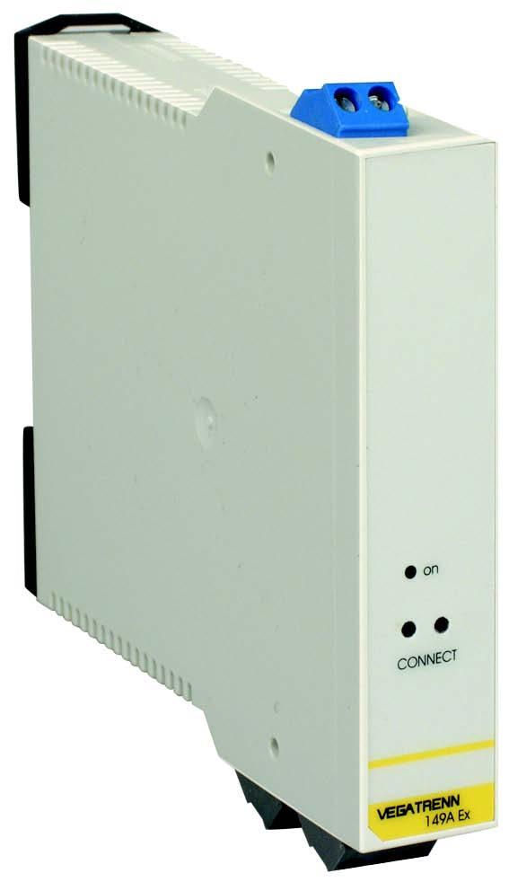
1 Separating and protective instruments Separating and protective instruments VEGATRENN 149AEx Separator type KFDO Barrier type 9001 Product Information
2 Content Content 1 Product description Type overview Mounting instructions Connecting to power supply 4.1 Preparing the connection Wiring plan Operation 5.1 Adjustment of the separators Adjustment of the sensor Technical data Dimensions Product code Take note of safety instructions for Ex applications Please note the Ex specific safety information which you will find on our homepage and which come with the appropriate instrument with Ex approval. In hazardous areas you should take note of the appropriate regulations, conformity and type approval certificates of the sensors and power supply units. Each with Ex approval is an associated, intrinsically safe instrument and must not be installed in hazardous areas. 2 Separating and protective instruments Separating and protective instruments
 l Separators (without external energy) Limitation of the electrical variables by: l Safety")
3 Product description 1 Product description Functional principle Separators separate intrinsically safe circuits from non-intrinsically safe circuits. In general, a difference is made between galvanic separation by: l Ex separators (with external energy) l Separators (without external energy) Limitation of the electrical variables by: l Safety barriers Ex separator The Ex separator is used as intrinsically safe power supply for Ex approved 4 20 ma/hart sensors. Through the auxiliary energy the sensor can be provided with more power. The instrument ensures a galvanic separation between sensor circuit and processing circuit and hence between Ex and non-ex areas. The load-independent 4 20 ma current is transmitted linearly to the output. The sockets in the front enable HART communication with the sensor via VEGACONNECT 3. The necessary communication resistance (R = 250 Ω) is already integrated in. Fig. 2: The safety barrier type 9001 is used for intrinsically safe measuring current transmissionin Ex Zone 1 without galvanic separation. It is hence suitable for connection of an indicating instrument to the non-intrinsically safe 4 20 ma output of a signal conditioning instrument. Safety barriers are also called zener barriers. Product properties: l Universal use for all 4 20 ma indicating instruments l Loop-powered, i.e. no additional power supply required Product properties: l Universal for all passive 4 20 ma/hart sensors l HART transmission to the output side l Sockets in the front for connection of VEGACONNECT l SIL 2 qualified Fig. 3: 1.1 Application examples Ex separator Fig. 1: Ex separator ma SPS Separator type KFD0 The separator KFD0-CS-Ex1.51P is used for intrinsically safe power supply and signal transmission of Ex approved 4 20 ma sensors. It is loop-powered without external energy. The instrument ensures a galvanic separation between sensor circuit and processing circuit and hence between Ex and non-ex areas. The load-independent 4 20 ma current is transmitted linearly to the output. However, a HART signal is not transmitted. Product properties: l Universal for all passive 4 20 ma sensors l Also in conjunction with signal conditioning instruments without own Ex approval l Loop-powered, i.e. no additional power supply required l Mounting of the separator in Ex zone 2 permitted V AC/DC Fig. 4: Intrinsically safe supply of an ultrasonic sensor via, indicationof the measured value or transmissionto a PLC/ controlsystem input card (4 20 ma) 1 Sensor 2 3 Indication 4 PLC/Control system/processing system Separating and protective instruments Separating and protective instruments 3


4 Product description ma 2 Fig. 5: Connection of a guided microwave sensor to a VEGALOG 571 processing system via the separator type KFD0 1 Sensor 2 3 VEGALOG 571 processing system Fig. 6: Connection of an indicating instrument to a VEGAMET signal conditioning instrument via the safety barrier type Sensor 2 3 VEGAMET signal conditioning instrument 4 Indication 4 Separating and protective instruments Separating and protective instruments
5 Type overview 2 Type overview Ex separator Separator Type KFD0-CS-Ex1.51P Safety barrier Type 9001 Applications: Galvanically separated voltage supplyofex approved4 20mA sensors Galvanic separation of intrinsically and non-intrinsically safe 4 20 ma circuits HART signal transmission: Yes No No Intrinsically safe measuring current transmission in Ex zone 1 Sensors: 4 20 ma passive 4 20 ma passive 4 20 ma indication Mounting: Carrier rail Carrier rail Carrier rail Ignition protection label: II (1)G D [EEx ia] IIC II (1)G D [EEx ia] IIC II (1/2)G [EEx ia/ib] IIC/IIB Separating and protective instruments Separating and protective instruments 5
6 Mounting instructions 3 Mounting instructions Installation All separators described in this product information manual are mounted on carrier rail 35 x 7.5 according to EN Separating and protective instruments Separating and protective instruments
7 Connecting to power supply 4 Connecting to power supply 4.1 Preparing the connection Note safety instructions Always keep in mind the following safety instructions: l Connect only in the complete absence of line voltage l If overvoltage surges are expected, overvoltage arresters should be installed Tip: We recommend VEGA overvoltage arresters B (external energy) and B62-36G (sensor supply). 4.2 Wiring plan Ex separator 1 I+ I- Take note of safety instructions for Ex applications In hazardous areas you should take note of the appropriate regulations, conformity and type approval certificates of the sensors and power supply units. 4 Select power supply The voltage supply for the Ex separator mustbeintherangeof20 250VAC,50/60Hzor20 250VDC. 0+H L/+ N/- Selecting connection cable For power supply of, an approved installation cable with PE conductor is necessary. The sensor or the signal conditioning instrument are connected with standard two-wire cable to the separator. If strong electromagnetic interference is expected, screened cable should be used. Cable screening and grounding If screened cable is used, connect the cable screen on both ends to ground potential. In the sensor, the screen must be connected directly to the internal ground terminal. The ground terminal on the outside of the housing must be connected to the potential equalisation. If potential equalisation currents are expected, the screen connection on the separator or signal processing instrument must be made via a ceramic capacitor (e. g. 1 nf, 1500 V). The low frequency potential equalisation currents are thus suppressed, but the protective effect against high frequency interference signals remains. 0+H L/+ N/- Fig. 7: Terminal assignment 1 Sensor circuit 2 Processing circuit 3 Power supply 4 HART communication sockets 2 3 Select connection cable for Ex applications Take note of the corresponding installation regulations for Ex applications. In particular, make sure that no potential equalisation currents flow over the cable screen. In case of grounding on both sides this can be achieved by the use of a capacitor or a separate potential equalisation. Separating and protective instruments Separating and protective instruments 7
8 Connecting to power supply 2- J U /01-086/150/ Fig. 8: Terminal assignment separator type KFD0-CS-Ex1.51P 1 Sensor circuit 2 Processing circuit Fig. 9: Terminal assignment safety barrier type Input circuit (non-intrinsically safe) 2 Output circuit (intrinsically safe) 8 Separating and protective instruments Separating and protective instruments
9 Operation 5 Operation 5.1 Adjustment of the separators After installation, the separators described in this product information manual are immediately ready for operation. An adjustment is not required. 5.2 Adjustment of the sensor A VEGA sensor powered via the can be also adjusted via the. You will need a Windows-PC with the configuration software PACTware and a suitable instrument driver (DTM) according to the FDT standard. For connection, the VEGACONNECT 3 interface converter with corresponding cable is required ma SPS 5 PACTware TM/ VEGA-DTM VEGACONNECT 3 Fig. 10: Adjustment of the sensor via VEGACONNECT 3 and VEGATRENN 149AEx 1 Sensor 2 3 Indication 4 HART adapter cable for VEGACONNECT 3 5 RS232 connection 6 PLC/Control system/processing system Necessary components: l Sensor l PC with PACTware and suitable VEGA DTM l VEGACONNECT 3 with HART adapter cable l Separating and protective instruments Separating and protective instruments 9
10 Technical data 6 Technical data General data Series Instrument for mounting on carrier rail 35 x 7.5 according to EN Dimensions Housing material Weight approx. W = 22.5 mm (0.89 in), H = 112 mm (4.41 in), D = 110 mm (4.33 in) Polycarbonate ABS, flammability class UL94V g (0.44 lbs) Series Instrument for mounting on carrier rail 35 x 7.5 according to EN Dimensions Weight approx. W = 20 mm (0.79 in), H = 115 mm (4.53 in), D = 107 mm (4.21 in) 100 g (0.22 lbs) Series Instrument for mounting on carrier rail 35 x 7.5 according to EN Dimensions Housing material Weight approx. B = 12.2 mm (0.48 in), H = 71.5 mm (2.81 in), T = 102 mm (4.01 in) Polyamide 6 GF 115 g (0.44 lbs) Sensor circuit Range 4 20 ma Supply voltage 16.7 V ±0.2 V (at 20 ma) Open-circuit voltage 26 V ±5 % Shortcircuit current 32 ma Inner resistance 328 Ω intrinsically safe (max. values in case of failure) Open-circuit voltage U o 27.3 V Shortcircuit current I o 84.1 ma Power P o 576 mw Capacitances - EEx ia IIC C o 86 nf - EEx ia IIB C o 683 nf - EEx ia IIA C o 683 nf Inductances - EEx ia IIC L o 5.5 mh - EEx ia IIB L o 20 mh - EEx ia IIA L o 20 mh Range 4 20 ma Output voltage - at 4 V < supply voltage < 24 V supply voltage - (0.4 x current in ma)v - 1 V - with supply voltage 24 V 23 V - (0.4 x current in ma)v Shortcircuit current 65 ma intrinsically safe (max. values in case of failure) Open-circuit voltage U o 25 V Shortcircuit current I o 93 ma Power P o 585 mw Capacitances - EEx ia IIC C o 2.41µF - EEx ia IIB C o 16.8µF - EEx ia IIA C o 75µF Inductances - EEx ia IIC L o 4 mh - EEx ia IIB L o 17 mh - EEx ia IIA L o 32 mh 10 Separating and protective instruments Separating and protective instruments
11 Technical data Input circuit Nominal voltage 6 V DC Zener voltage 8.6 V Leakage current against ground with U Nom 1µA min. longitudinal resistance 64 Ω max. longitudinal resistance 73 Ω Processing/Output circuit Open-circuit voltage 24 V ±10 % Max. load - without communication resistance 700 Ω - with communication resistance 450 Ω Voltage 4 35 V DC Current 40 ma Power loss - with 40 ma and voltage < 24 V 700 mw - with 40 ma and voltage 24 V 1.2 W Indication circuit Shortcircuit current 150 ma Capacitances - EEx ia IIC C o 6.2µF - EEx ia IIB C o 55µF Inductances - EEx ia IIC L o 1.3 mh - EEx ia IIB L o 7 mh Ambient conditions Ambient temperature Storage and transport temperature Ambient temperature Ambient temperature Storage and transport temperature C ( F) C ( F) C ( F) C ( F) C ( F) Voltage supply Supply voltage Max. power consumption V AC, 50/60 Hz V DC 2.4 W Electrical protective measures Protection IP 20 Separating and protective instruments Separating and protective instruments 11
12 Technical data Separator type KFD0 Protection IP 20 Protection - Terminal bearing IP 20 - Housing IP 40 Electrical separating measures Galvanic separation Galvanic separation Output circuit of all other circuits Output circuit to input circuit Approvals 1) ATEX ATEX ATEX II (1)G D [EEx ia] IIC II (1)G D [EEx ia] IIC II (1/2)G [EEx ia/ib] IIC/IIB Environmental instructions VEGA environment management system certified according to DIN EN ISO You can find detailed information under 1) Deviating data in Ex applications: see separate safety instructions. 12 Separating and protective instruments Separating and protective instruments
13 on CONNECT 149AEx Dimensions 7 Dimensions 22,5mm (57/64") 112mm (4 13/32") 96mm (3 25/32") 110mm (4 21/64") Fig. 11: Dimensions 20mm (25/32") 115mm (4 17/32") 107mm (4 7/32") Fig. 12: Dimensions separator type KFD0-CS-Ex1.51P 12,2 mm (31/64") 71,5mm (2 25/64") mm (4 1/64") 9001/ Fig. 13: Dimensions safety barrier type 9001 Separating and protective instruments Separating and protective instruments 13
14 Product code 8 Product code Approval EX.X ATEX II (1) G D [EEx ia] IIC TRENN149A KFD0-CS-EX1.51P TRENN Separating and protective instruments Separating and protective instruments
15 Separating and protective instruments Separating and protective instruments 15

16 VEGA Grieshaber KG Am Hohenstein Schiltach Germany Phone Fax You can find at downloads of the following l operating instructions manuals l menu schematics l software l certificates l approvals and much, much more Subject to change without prior notice
Safety instructions. IECEx TUN Ex ia IIC T6 Gb
 Safety instructions ÜSB62-36G.C_* and ÜSB62-30W.C_* IECEx TUN 07.0002 Ex [ia Ga] IIC T6 Gb Ex ia IIC T6 Gb 0044 39878 Content 1 Area of applicability 3 2 General 3 3 Electrical data 3 3.1 Application conditions
Signal conditioning instruments VEGASCAN 693. Product Information
 Signal conditioning instruments VEGASCAN 693 Product Information Content Content 1 Product description.......................................................................... 3 2 Type overview..............................................................................
Signal conditioning instruments for level switches. Conductive VEGATOR 256C VEGATOR 532 VEGATOR 631. Product Information
 Signal conditioning instruments for level switches Conductive VEGATOR C VEGATOR VEGATOR Product Information Content Content Product description..........................................................................
Safety instructions VEGATOR 121, 122
 Safety instructions Intrinsic safety IECEx TUN 14.0005X Document ID: 47471 Contents 1 Area of applicability... 3 2 General information... 3 3 Technical data... 3 4 Installation... 4 Supplementary documentation:
Operating Instructions
 Operating Instructions t i SPAN NOT USED - - 4...20mA DISPLAY t i SPAN END POINT DISPLAY Ð - 4...20mA p Safety information, Note Ex area Safety information Please read this manual carefully, and also take
Indication and Adjustment Product Information VEGADIS 61. Level Switching Pressure
 Indication and Adjustment Product Information VEGADIS 61 Level Switching Pressure 2 VEGADIS 61 Contents Contents 1 Product description...4 1.1 Configuration... 4 1.2 Principle of operation... 4 1.3 Adjustment...
Safety instructions Overvoltage protection B81-35
 Safety instructions Overvoltage protection B81-35 IECEx BVS 15.0084X Intrinsic safety Document ID: 51001 Contents 1 Area of applicability... 3 2 General information... 3 3 Technical data... 5 4 Application
VEGAMET 381 VEGAMET 624 VEGAMET 625
 Signal conditioning instruments VEGAMET 64 VEGAMET 65 Product Information Contents Contents Product description... 3 Type overview.... 4 3 Mounting instructions... 5 4 Connecting to voltage supply 4. Preparing
4 â Active barrier RN221N with optional HART diagnosis. Technical Information
 Technical Information Active barrier with optional HART diagnosis Active barrier with power supply for safe separation of 4 to 20 ma current circuits Application Galvanic isolation of 4 to 20 ma current
4 Remote I/O. Digital Output Module 8-Channel Version Type 9475/ from Rev. F
 4 Remote I/O Digital Output Module 8-Channel Version 8 channels for Ex i solenoid valves, piezo and booster-valves Intrinsically safe Ex ia IIC outputs Additional input for Plant-STOP available (acc. to
4 Remote I/O. Analog Output Module HART Ex i / I.S. Outputs, 8 Channels Series 9466/12
 0 4 Remote I/O 8 channels for controlling HART control valves and positioners Intrinsically safe outputs Ex ia IIC Galvanic isolation between outputs and system Open-circuit and short-circuit monitoring
Interface and Supply module. IPC 3x0i / PSC 3x0i
 Interface and Supply module IPC 3x0i / PSC 3x0i Installation Guide Version 10 IBS BatchControl GmbH Im Sträßchen 2 4 Tel.: +49 2241 9199801 53925 Kall Fax.: +49 2241 9199871 Germany www.ibs-batchcontrol.com
Product information Ultrasonic
 Product information Ultrasonic Level measurement in liquids and bulk solids VEGASON 6 VEGASON 6 VEGASON 6 Document ID: 90 Contents Contents Measuring principle... Type overview... 4 Instrument selection...
Isolating repeater IRU 420
 Isolating repeater IRU 420 Universal intrinsically safe isolating repeater of current signals 0/4 20 ma with option voltage output 0 10 V For supply sensors with output 0/4 20 ma in Galvanic separation
SYSTEM COMPONENTS SYSTEM COMPONENTS MODULES
 SYSTEM COMPONENTS SYSTEM COMPONENTS MODULES O U R P R O F E S S I O N MULTIFUNCTIONAL CURRENT CONTROLLED SWITCH MODULES MAIN FEATURES 4 20 ma input Relay output Rail mountable Intrinsically safe Associated
PI-EX-ME-2NAM/COC-24VDC
 Ex-i NAMUR Isolation Amplifier, With Intrinsically Safe Input and Relay Output, PDT, Two-Channel, 4 V DC Supply INTERFACE Data Sheet 0033_0_en PHOENIX CONTACT - /007 Description The PI-EX-ME-NAM/COC-4VDC
Operating Instructions. Intrinsically Safe Isolation Relay for Switches Model: REL manual_rel-6_0505
 Operating Instructions Intrinsically Safe Isolation Relay for Switches Model: REL-6003 manual_rel-6_0505 1. Contents 1. Contents...2 2. Note...3 3. Instrument Inspection...3 4. Regulation Use...3 5. Operating
PHOENIX CONTACT - 12/2007
 Ex-i NAMUR Isolation Amplifier, With Intrinsically Safe Input and Active Transistor Output, Two-Channel INTERFACE Data Sheet 0943_00_en PHOENIX CONTACT - /007 Description The PI-EX-ME-NAM/TO-A is a two-channel
5 Fieldbus Technology
 5 Fieldbus Technology Ex e / Ex i 10922E00 The s Ex e/ex i connect intrinsically safe Foundation Fieldbus H1 or Profibus PA field devices to a non-intrinsically safe / Ex e trunk. Up to four intrinsically
Digital Output Module 4-Channel Version for Zone 1 Series 9475/
 www.stahl.de > 4-channel digital output > Intrinsically safe outputs Ex ib > Suitable for Ex i hydraulic valves and solenoid valves > Additional Ex i control input for (in accordance with IEC 61508 through
Digital Output Module 4-Channel Version for Zone 1 Series 9475/
 www.stahl.de > 4-channel digital output > Intrinsically safe outputs Ex ia > For Ex i solenoid valves and display elements > Additional Ex i control input for "Plant STOP" (acc. IEC61508 up to SIL2) >
WG 20. The WG 20 achieves an extraordinarily. accuracy for hazardous-area. applications.
 Modular Housings for Hazardous Areas For transmission of 0(4)... 20-mA signals from hazardous areas or supply of intrinsically safe 2-wire transmitters. The Task The power supply/isolator is used to supply
Digital Output Module 8-Channel Version for Zone 1 Series 9475/
 www.stahl.de > 8-channel digital output > Intrinsically safe outputs Ex ia > For Ex i solenoid valves and display elements > Additional Ex i control input for "Plant STOP" (acc. IEC61508 up to SIL2) >
PI-EX-ME-2NAM/COC-120VAC
 PI-EX-ME-NAM/COC-0VAC Ex-i NAMUR Isolation Amplifier, With Intrinsically Safe Input and Relay Output, PDT, Two-Channel, 0 V AC Supply INTERFACE Data Sheet 0944_00_en PHOENIX CONTACT - 0/008 Description
4 Remote I/O. Digital Output Module 8-Channel Version Series 9475/ from Rev. F
 4 Remote I/O Digital Output Module 8-Channel Version 8 channels for Ex i / I.S. solenoid valves, piezo and booster valves Intrinsically safe outputs Ex ia IIC Additional input for "Outputs OFF" available
Safety Barriers. CEAG safety barriers can be used for all kinds of instrumentation applications.
 Safety Barriers Description Safety barriers limit the energy fed to an intrinsically safe circuit so that neither sparks nor thermal effects (hot surfaces) can cause an explosion. CEAG safety barriers
Digital Output Module 8-Channel Version for Zone 2 Series 9475/
 > 8-channel digital output > Intrinsically safe outputs Ex ia > For Ex i solenoid valves and display elements > Line fault monitoring per channel > Diagnostics based on NE107 > Module can be replaced in
Loop-powered Transmitter for Thermocouple Type K (NiCr-Ni)
") Data sheet 302040_en MTP300i-SIL-K Loop-powered Transmitter for Thermocouple Type K (NiCr-Ni) Properties 2-wire temperature transmitter for DIN rails Galvanic isolated TC-input with cold-junction compensation
Data sheet 302040_en MTP300i-SIL-K Loop-powered Transmitter for Thermocouple Type K (NiCr-Ni) Properties 2-wire temperature transmitter for DIN rails Galvanic isolated TC-input with cold-junction compensation
Intrinsically Safe Barriers
 Intrinsically Safe Barriers Description Page No. Safety Barriers 464-472 Din Rail Isolated Barriers 473-488 477 Intrinsically Safe Barriers Product Overview We have simplified intrinsic safety! Cooper
English. Operating Manual. Universal Isolating Amplifier TV125M / ST125M. Save for later reference. Companies / Brands of GHM
 English Operating Manual Universal Isolating Amplifier TV125M / ST125M Companies / Brands of GHM www.ghm-messtechnik.de Save for later reference. Table of contents Page 1 Intended use (areas of application)...
PHOENIX CONTACT - 02/2008
 Ex-i solenoid driver for Group IIC gases, loop-powered, pluggable INTERFACE Data Sheet 103211_00_en PHOENIX CONTACT - 02/2008 1 Description The solenoid driver PI-EX-SD-21-25 links a signaling device installed
Assembly. Front view. LED yellow: Relay output. LED red: LB/SC Power Rail
 Switch Amplifier Features Assembly -channel isolated barrier 4 V DC supply (Power Rail) Dry contact or NAMUR inputs Relay contact output Line fault detection (LFD) Reversible mode of operation Up to SIL
PROFIBUS-PA Positioner Type 3785
 PROFIBUS-PA Positioner Type 3785 Application Single-acting or double-acting PROFIBUS-PA positioner for attachment to pneumatic control valves. Rated travel from 7.5 to 120 mm Opening angle up to 120 Smart,
Termination Board FC-GPCS-SAI16-PF. Features. Assembly. Function. Connection. SAI-1620m HART 24 V DC (I), 24 V DC (II) Fault. Zone 0, 1, 2 Div.
, 24 V DC (II) Fault. Zone 0, 1, 2 Div.") Features Assembly System board for Honeywell Safety Manager For 6-channel AI card SAI-60m For 6 modules Recommended module: HiC05 (AI) 4 V DC supply Hazardous area: pluggable screw terminals, blue Non-hazardous
Features Assembly System board for Honeywell Safety Manager For 6-channel AI card SAI-60m For 6 modules Recommended module: HiC05 (AI) 4 V DC supply Hazardous area: pluggable screw terminals, blue Non-hazardous
MACX MCR-EX-SD LP(-SP)
") Intrinsically safe solenoid driver for Group IIC gases, loop-powered, current limit 48 ma INTERFACE Data sheet 103468_en_01 PHOENIX CONTACT - 08/2008 1 Description The solenoid driver MACX MCR-EX-SD-24-48-LP(-SP)
Intrinsically safe solenoid driver for Group IIC gases, loop-powered, current limit 48 ma INTERFACE Data sheet 103468_en_01 PHOENIX CONTACT - 08/2008 1 Description The solenoid driver MACX MCR-EX-SD-24-48-LP(-SP)
Operating instructions (Safety-related part ATEX and IECEx) Inductive NAMUR sensors NN504A NN505A NN506A NN507A /00 08/2015
 Inductive NAMUR sensors NN504A NN505A NN506A NN507A /00 08/2015") Operating instructions (Safety-related part ATEX and IECEx) Inductive NAMUR sensors NN504A NN505A NN506A NN507A 80013497/00 08/015 Remarks for safe use in hazardous areas Functions and features Use in
Operating instructions (Safety-related part ATEX and IECEx) Inductive NAMUR sensors NN504A NN505A NN506A NN507A 80013497/00 08/015 Remarks for safe use in hazardous areas Functions and features Use in
TFR5. Room or outdoor temperature sensor. Operating instructions for temperature sensor. English page 1...5
 EN/2018-03-14 Design and specifications subject to change without notice Operating instructions for temperature sensor English page 1...5 Field of application CombiTemp is a temperature sensor, based on
Digital Output Module 8-Channel Version for Zone 2 Series 9475/
 > 8-channel digital output > Intrinsically safe outputs Ex ia > For Ex i solenoid valves and display elements > Line fault monitoring per channel > Diagnostics based on NE107 > Module can be replaced in
ADAMCZEWSKI. Ordering data AD-STVEX 710 GVD Option: Factory-software configuration as per customer specifications.
 EN ADAMCZEWSKI Elektronische Messtechnik GmbH Felix-Wankel-Str. 13 / 74374 Zaberfeld Tel. +49 (0)7046-875 Fax +49 (0)7046-7678 vertrieb@ad-messtechnik.de Operating Instructions Supply Isolation Amplifier
MINI MCR-SL-RPS-I-I. Repeater power supply, active. Data sheet. 1 Description
 Repeater power supply, active Data sheet 09_en_0 PHOENIX CONTACT 0--0 Description The. mm wide... repeater power supply supplies transmitters in the field and electrically isolates the input signal from
Supplementary instructions. Plug connector Harting HAN 8D. for continuously measuring sensors. Document ID: 30376
 Supplementary instructions Plug connector Harting HAN 8D for continuously measuring sensors Document ID: 30376 Contents Contents 1 For your safety 1.1 Appropriate use... 3 1.2 Impermissible use... 3 1.3
FieldIT Multi Barrier NMB204/NMB204-EX (MB 204/MB 204-Ex)
") Data Sheet FieldIT Multi Barrier NMB204/NMB204-EX (MB 204/MB 204-Ex) Intrinsically safe power supply of up to 31 stations on the bus cascadable multi barrier Intrinsically safe connection of up to 4 field
Data Sheet FieldIT Multi Barrier NMB204/NMB204-EX (MB 204/MB 204-Ex) Intrinsically safe power supply of up to 31 stations on the bus cascadable multi barrier Intrinsically safe connection of up to 4 field
Inductive angle sensor with analog output Ri360P1-DSU35TC-ELi-Exi
 ATEX category II 2 G, Ex Zone 1 ATEX category II 2 D, Ex Zone 21 Rectangular, housing DSU35 Plastic, PP-GF30-VO Detection of angular range 0 to 360 P1-Ri-QR14 positioning element included in delivery Measuring
Operating Instructions VEGAMET 381
 Operating Instructions VEGAMET 381 in out Contents Contents 1 About this document... 4 1.1 Function... 4 1.2 Target group... 4 1.3 Symbolism used... 4 2 For your safety... 6 2.1 Authorised personnel...
Trendmaster* Galvanic Isolator
 162459-01 Trendmaster* Galvanic Isolator Product Datasheet Bently Nevada* Asset Condition Monitoring Description The Trendmaster Galvanic Isolator enables the Trendmaster system to connect to intrinsically
Assembly. Front view. LED yellow/red: Status output Ι/ Fault signal Function. Switch Power Rail
 Switch Amplifier KCD-SR-Ex.LB Features Assembly -channel isolated barrier V DC supply (Power Rail) Dry contact or NAMUR inputs Usable as signal splitter ( input and outputs) Relay contact output Fault
Operating Instructions VEGAMET 391. Signal conditioning and display instrument for level sensors ma/hart. Document ID: 36032
 Operating Instructions Signal conditioning and display instrument for level sensors VEGAMET 391 4 20 ma/hart Document ID: 36032 2 Contents Contents 1 About this document 1.1 Function... 4 1.2 Target group...
PHOENIX CONTACT - 05/2007
 Ex Universal Module Carrier (Motherboard) for Accommodating 3-Wire Measuring Transducers, Intrinsically Safe, for a Maximum of 8 PI Ex Modules INTERFACE Data Sheet 103030_00_en PHOENIX CONTACT - 05/2007
Float Switches with Permanent Magnet For Vertical Installation Model RSM
 Level Measurement Float Switches with Permanent Magnet For Vertical Installation Model RSM WIKA Data Sheet LM 30.01 Applications Level measurement for almost all liquid media Pump/level control and monitoring
SIMATIC Distributed I/O Product information for the ET 200iSP Operating Instructions (A5E ) 01/2010
 01/2010") SIMATIC Distributed I/O Product information for the ET 200iSP Operating Instructions (A5E00247483-04) 01/2010 Product Information Order number Type Order number 4 DO DC23.1V/20mA SHUT DOWN "H" 6ES7132-7RD01-0AB0
SIMATIC Distributed I/O Product information for the ET 200iSP Operating Instructions (A5E00247483-04) 01/2010 Product Information Order number Type Order number 4 DO DC23.1V/20mA SHUT DOWN "H" 6ES7132-7RD01-0AB0
Intrinsically Safe Explosion Proof Barriers
 Safety Intrinsically Safe Explosion Proof For more information on this product family, visit our website. Additional resources include: New and updated product information Downloadable software demos &
Product information. Radar. Level measurement in bulk solids VEGAPULS 67 VEGAPULS SR 68 VEGAPULS 68 VEGAPULS 69. Document ID: 29427
 Product information Level measurement in bulk solids VEGAPULS 67 VEGAPULS SR 68 VEGAPULS 68 VEGAPULS 69 Document ID: 97 Contents Contents Measuring principle... Type overview... Instrument selection...
Termination Board FC-GPCS-RIO16-PF. Features. Assembly. Function. Connection USIO/UPIO 24 V DC (I), 24 V DC (II) Fault. Zone 0, 1, 2 Div.
, 24 V DC (II) Fault. Zone 0, 1, 2 Div.") Features Assembly System board for Honeywell Universal Safety IO System board for Honeywell Universal Process IO For 6-channel cards USIO and UPIO For 6 modules Recommended modules: HiC8R (DI), HiC85R
Features Assembly System board for Honeywell Universal Safety IO System board for Honeywell Universal Process IO For 6-channel cards USIO and UPIO For 6 modules Recommended modules: HiC8R (DI), HiC85R
CPU module for zone 2 Series 9442/35
 > Supports PROFIBUS DP, PROFINET, Modbus TCP and Ethernet/IP; incl. HART transmission > RS-485 (max. 12 Mbps) and Ethernet (max. 100 Mbps) interfaces > Extensive diagnostics based on NE 107 > Support of
Operating Instructions VEGAMET 391. Signal conditioning and display instrument for level sensors ma/hart. Document ID: 36032
 Operating Instructions Signal conditioning and display instrument for level sensors VEGAMET 391 4 20 ma/hart Document ID: 36032 2 Contents Contents 1 About this document... 4 1.1 Function... 4 1.2 Target
Float Switches with Permanent Magnet For Horizontal Installation Model HIF
 Level Measurement Float Switches with Permanent Magnet For Horizontal Installation Model HIF WIKA Data Sheet LM 30.02 Applications Level measurement for almost all liquid media Pump/level control Chemical
Series 3730 Electropneumatic Positioner Type
 Series 3730 Electropneumatic Positioner Type 3730-0 Application Single-acting or double-acting positioner for attachment to pneumatic control valves Reference variable Travels 4 to 20 ma 5.3 to 200 mm
Operating Instructions
 Introduction To protect the signal lines of field devices and systems in the cabinet against lightning. Pepperl+Fuchs covers the complete range of Surge Protection Barriers. Housing types Depending on
Supplementary instructions. VEGADIS adapter. For connection of an external display and adjustment unit or a slave sensor. Document ID: 45250
 Supplementary instructions VEGADIS adapter For connection of an external display and adjustment unit or a slave sensor Document ID: 45250 Contents Contents 1 For your safety 1.1 Appropriate use... 3 1.2
VariTrans B The world s first 3-port standard signal isolator in a 6-mm modular housing.
 Standard-Signal Isolation Amplifiers The world s first 3-port standard signal isolator in a 6-mm modular housing. The Task Isolation and, if required, conversion of 0... 20 ma, 4... 20 ma, and 0... 10
Product information. Hydrostatic. Submersible pressure transmitter VEGABAR 86 VEGABAR 87 VEGAWELL 52. Document ID: 45079
 Product information Submersible pressure transmitter VEGABAR 86 VEGABAR 87 VEGAWELL Document ID: 079 Contents Contents Measuring principle... Type overview... Instrument selection... Selection criteria...
MINI MCR-SL-UI-2I. Configurable signal duplicator. Data sheet. 1 Description
 Configurable signal duplicator Data sheet 102382_en_03 PHOENIX CONTACT 2012-05-02 1 Description The MINI MCR-SL-UI-2I(-SP)(-NC) configurable signal duplicator is used to electrically isolate, condition,
Operating Instructions SU 600 Ex
 Operating Instructions SU 600 Ex 4 20 ma signal conditioning instrument Document ID: 30653 2 Contents Contents 1 About this document 1.1 Function... 3 1.2 Target group... 3 1.3 Symbols used... 3 2 For
Operating Instruction
 Level and Pressure Operating Instruction VEGASWING 71 A Contents Contents Safety information... 2 1 Product description 1.1 Function and configuration... 3 1.2 Functional principle... 3 1.3 Technical data...
MANUAL Surge Protectors
 PROCESS AUTOMATION MANUAL Surge Protectors DP-LBF-I1.36.DE and DP-LBF- I1.36.IE With regard to the supply of products, the current issue of the following document is applicable: The General Terms of Delivery
INSTRUCTION MANUAL. Universal AC Input Switching Power Supply 24 Vdc Output DIN-Rail Models PSD1000, PSD1000F PSD PSD1000F
 PSD1000 - PSD1000F INSTRUCTION MANUAL Universal AC Input Switching Power Supply 24 Vdc Output DIN-Rail Models PSD1000, PSD1000F PSD1000 - Universal AC Input Switching Power Supply 24 Vdc Output ISM0089-4
MINI MCR-SL-PT100-UI. Active resistance thermometer measuring transducer. Data sheet. 1 Description
 Active resistance thermometer measuring transducer Data sheet 099_en_06 PHOENIX CONTACT 0-0- Description The 6. mm wide MINI MCR-SL-PT00-UI-... is a configurable, -way isolated temperature measuring transducer.
Supplementary instructions. Plug connector Harting HAN 7D. For point level sensors. Document ID: 34456
 Supplementary instructions Plug connector Harting HAN 7D For point level sensors Document ID: 446 Contents Contents For your safety.... Appropriate use.... General safety instructions.... Safety instructions
Sense it! Connect it! Bus it! Solve it! REMOTE I/O excom
 Sense it! Connect it! Bus it! Solve it! REMOTE I/O excom Remote I/O System excom Intrinsically safe remote I/O system for use in zone 1 and zone 2 Redundant power supplies and gateways Intrinsically safe
Process display RIA 251. Digital loop powered display for ma current loops. Application areas. Plant and machine construction.
 Technical information TI 063R/09/en Mat. No. 510 00857 Process display RIA 251 Digital loop powered display for 4...20 ma current loops Application areas Plant and machine construction Control panels Laboratory
Termination Board. HiCTB08-SCT-44C-SC-RA. Features. Assembly. Function. Connection. 24 V DC (I), 24 V DC (II), Fault. Zone 0, 1, 2 Div.
, 24 V DC (II), Fault. Zone 0, 1, 2 Div.") Termination Board HiCTB08-SCT-C-SC-RA Features Assembly For 8 modules V DC supply Supported signal types: DI/DO/AI/TI/AO Hazardous area: screw terminals, blue Safe area: screw terminals, black Function
Termination Board HiCTB08-SCT-C-SC-RA Features Assembly For 8 modules V DC supply Supported signal types: DI/DO/AI/TI/AO Hazardous area: screw terminals, blue Safe area: screw terminals, black Function
Signal processor MS96 for flow sensors MS96-11EX0-R/230VAC
 MS96-11EX0-R/230VAC ATEX category II (1) G, Ex Zone 0 ATEX category II (1) D, Ex Zone 20 single-channel signal processor MS96 for connection of an intrinsically safe flow control sensor in zone 0 adjustment
Inductive sensor BI5-EM18-Y1X-H1141
 ATEX category II 1 G, Ex zone 0 ATEX category II 1 D, Ex zone 20 SIL2 (Low Demand Mode) acc. to IEC 61508, PL c acc. to ISO 13849-1 at HFT0 SIL3 (All Demand Mode) acc. to IEC 61508, PL e acc. to ISO 13849-1
Data Sheet T 8394 EN. Series 3725 Type 3725 Electropneumatic Positioner
 Data Sheet T 8394 EN Series 3725 Type 3725 Electropneumatic Positioner Application Single-acting positioner for attachment to pneumatic globe and rotary valves. Self-calibrating, automatic adaptation to
MACX MCR-EX-SL-RPSSI-I(-SP)
") Repeater power supply and input isolating amplifier, Ex-i Data sheet 103568_en_02 PHOENIX CONTACT 2015-03-26 1 Description The repeater power supply and input signal conditioner is designed for the intrinsically
Repeater power supply and input isolating amplifier, Ex-i Data sheet 103568_en_02 PHOENIX CONTACT 2015-03-26 1 Description The repeater power supply and input signal conditioner is designed for the intrinsically
FEATURES. Nominal Output Voltage and Current
 5W, AC-DC converter FEATURES 85-264V Universal AC or wide 100-370V DC Input Operating ambient temperature range: -40 to +85 High I/O isolation test voltage of up to 4000VAC Regulated output, Low ripple
Intrinsically safe batch controller Batching Master 110i
 Intrinsically safe batch controller Batching Master 110i Installation Guide BVS 04 AT E 172 Revision 12.2 IBS BatchControl GmbH Im Sträßchen 2-4 Tel.: ++49 2441 9199 801 53925 Kall Fax.: ++49 2441 9199
FB-6SP and FB-12SP. Block device couplers. Data sheet 3177_en_A. 2 Features. 1 Description
 Block device couplers Data sheet 3177_en_A 1 Description PHOENX CONTACT 2015-01-20 2 Features The and block couplers provide an interface between the fieldbus trunk cable and field devices on Foundation
Assembly MAU. MUX 4 Channels 8 Channels Zone 1
 Multi-Input/Output Device for Cabinet Installation Features Assembly For discrete inputs and outputs Installation in Zone 1/Div. 1, intrinsically safe Sensors in Zone 0/Div. 1 Connection to fieldbus acc.
Assembly MAU. MUX 4 Channels 8 Channels Zone 1
 Multi-Input/Output Device for Cabinet Installation Features Assembly For discrete inputs and outputs Installation in Zone 1/Div. 1, intrinsically safe Sensors in Zone 0/Div. 1 Connection to fieldbus acc.
Zener Barriers Bulletin 937Z
 Technical Data Zener Barriers Bulletin 937Z Topic Page Introduction 2 Mounting 2 Housing 3 Operating Principle 3 Specifications 6 Introduction Allen-Bradley Zener barriers are a cost-effective solution
System Components Surge Arrester HAW 261 and HAW 262
 Technical Information TI 108F/00/en System Components Surge Arrester and Operating Instructions Part. No. 017166-1000 for power supply side for signal input side (2-wire) (2 and 3-wire) Application The
D1093S INSTRUCTION MANUAL. D SIL 3 Relay Output Module with Line and Load diagnostics. DIN-Rail Model D1093S
 D109S INSTRUCTION MANUAL SIL Relay Output Module with Line and diagnostics DINRail Model D109S D109 SIL Relay Output Module with Line and diagnostics ISM0096 SIL Applications For Safety Related System
MACX MCR-EX-SL-NAM-R(-SP)
") Intrinsically safe NAMUR isolating amplifier with relay output INTERFACE Data sheet 03463_en_00 PHOENIX CONTACT - 08/2008 Description The NAMUR MACX MCR-EX-SL-NAM-R(-SP) isolating amplifier has been designed
Intrinsically safe NAMUR isolating amplifier with relay output INTERFACE Data sheet 03463_en_00 PHOENIX CONTACT - 08/2008 Description The NAMUR MACX MCR-EX-SL-NAM-R(-SP) isolating amplifier has been designed
MACX MCR-EX-SL-NAM-2RO(-SP)
") Intrinsically safe NAMUR isolating amplifier with two relay outputs INTERFACE Data sheet 03465_en_00 PHOENIX CONTACT - 08/008 Description The NAMUR MACX MCR-EX-SL-NAM-RO(-SP) isolating amplifier has been
Intrinsically safe NAMUR isolating amplifier with two relay outputs INTERFACE Data sheet 03465_en_00 PHOENIX CONTACT - 08/008 Description The NAMUR MACX MCR-EX-SL-NAM-RO(-SP) isolating amplifier has been
Series 3730 Electropneumatic Positioner Type with HART communication and pressure sensors
 Series 3730 Electropneumatic Positioner Type 3730-6 with HART communication and pressure sensors Application Single-acting or double-acting positioner for attachment to pneumatic control valves. Self-calibrating,
Easy Analog RNB130. Technical Information. Primary switched-mode power supply
 Technical Information Easy Analog RNB130 Primary switched-mode power supply Your benefits Small housing, 35 mm (1.38") width High availability Wide range input - can be used world-wide Power reserve (Power
MINI MCR-SL-UI-2I-NC. Extract from the online catalog. Order No.:
 Extract from the online catalog MINI MCR-SL-UI-2I-NC Order No.: 2864176 4-way signal duplicator for electrical isolation and duplication of analog signals with screw connection, standard configuration
Segment Protector for Cabinet Installation R2-SP-IC* Features. Assembly. Function. Connection. Trunk, Ex na non-arcing. Spur.
 egment Protector for Cabinet nstallation Features Assembly 4... 12 outputs Ex ic (FCO or Entity) or non-incendive (Div 2) Advanced fault isolation at the spur egment Protector in Zone 2/Div. 2 nstruments
MODEL: MD7ST. [3] LOOP DISCONNECT FUSE 0: Without 1: With (CENELEC/ATEX approval Not selectable)
![MODEL: MD7ST. [3] LOOP DISCONNECT FUSE 0: Without 1: With (CENELEC/ATEX approval Not selectable)](/thumbs/75/72960218.jpg "MODEL: MD7ST. [3] LOOP DISCONNECT FUSE 0: Without 1: With (CENELEC/ATEX approval Not selectable)") MODEL: MDST Lightning Surge Protectors for Electronics Equipment M-RESTER LIGHTNING SURGE PROTECTOR FOR STANDARD SIGNAL LINE (ultra-slim) Functions & Features High discharge current capacity 0 ka ( / 0μs),
MODEL: MDST Lightning Surge Protectors for Electronics Equipment M-RESTER LIGHTNING SURGE PROTECTOR FOR STANDARD SIGNAL LINE (ultra-slim) Functions & Features High discharge current capacity 0 ka ( / 0μs),
How to calculate an Intrinsically Safe loop approval.
 MIE TALK - October 2016 How to calculate an Intrinsically Safe loop approval. EXPLOSIVE ATMOSPHERES Compile by: Gary Friend BSc PrEng, CEng MIET, Sales DirectorExtech Safety Systems (MTL, Beka Associates,
Inductive sensor BI1.5-EG08-Y1-H1341
 ATEX category II 1 G, Ex zone 0 ATEX category II 1 D, Ex zone 20 SIL2 (Low Demand Mode) acc. to IEC 61508, PL c acc. to ISO 13849-1 at HFT0 SIL3 (All Demand Mode) acc. to IEC 61508, PL e acc. to ISO 13849-1
Magnetic field sensor Magnetic-inductive Proximity Sensor BIM-M12E-Y1X
 ATEX category II 1 G, Ex zone 0 ATEX category II 1 D, Ex zone 20 SIL2 as per IEC 61508 Threaded barrel, M12 x 1 Chrome-plated brass Rated operating distance 90 mm with DMR31-15-5 magnet DC 2-wire, nom.
VISY. Technical Documentation. VISY-Command (VI-4) Version: 6 Edition: Art. no.:
 Version: 6 Edition: Art. no.:") Technical Documentation VISY VISY-Command (VI-4) Version: 6 Edition: 2017-09 Art. no.: 207184 FAFNIR GmbH Schnackenburgallee 149 c 22525 Hamburg Tel.: +49 / 40 / 39 82 07-0 Fax: +49 / 40 / 390 63 39 Table
Technical Documentation VISY VISY-Command (VI-4) Version: 6 Edition: 2017-09 Art. no.: 207184 FAFNIR GmbH Schnackenburgallee 149 c 22525 Hamburg Tel.: +49 / 40 / 39 82 07-0 Fax: +49 / 40 / 390 63 39 Table
Operating Instructions. VEGA DataViewer. Software for archive, administration and display of DTM data. Document ID: 51547
 Operating Instructions Software for archive, administration and display of DTM data VEGA DataViewer Document ID: 51547 Contents Contents 1 About this document... 3 1.1 Function... 3 1.2 Target group...
Operating instructions
 Operating instructions Digital Input Output Module > Contents 1 Contents 1 Contents...2 2 General information...3 2.1 Manufacturer...3 2.2 Information regarding the operating instructions...3 2.3 Conformity
PROCESS AUTOMATION INSTRUCTION MANUAL FIELDBUS SURGE PROTECTOR F*-LBF-I1.32 F*-LBF-D1.32
 PROCESS AUTOMATION INSTRUCTION MANUAL FIELDBUS SURGE PROTECTOR F*-LBF-I1.32 F*-LBF-D1.32 With regard to the supply of products, the current issue of the following document is applicable: The General Terms
Article No. 6GK59230PS003AA2 6GK59240PS001AA2 Product Name. Power Supply SCALANCE PS924 PoE Input: 120/230V AC; Output: 54V/ 1.
 Product Name Type of power supply Electrical data Input Waveform of the input Supply Power Supply SCALANCE PS924 PoE Input: 120/230V AC; Output: 54V/ 1.6A DC; NEC Class 2 single-phase AC Power Supply SCALANCE
Level measurement. Applications. Special features. Description
 Level measurement Optoelectronic level switch Model OLS-S, for the process industry (with Ex i approval: KSR-OPTO.21*06XX) Model OSA-S, switching amplifier (with Ex i approval: KSR-OPTO.2502.XX) KSR data
Segment Protector for Cabinet Installation R2-SP-IC* Features. Assembly. Function. Connection. Trunk, Ex na non-arcing. Spur.
 egment Protector for Cabinet nstallation Features Assembly 4... 12 outputs Ex ic (FCO or Entity) or non-incendive (Div 2) Advanced fault isolation at the spur egment Protector in Zone 2/Div. 2 nstruments