83132 / / Subminiature Double Break Switches... 3/ Subminiature Switches... 3/ Sealed Subminiature Switches...
|
|
|
- Linette Whitehead
- 5 years ago
- Views:
Transcription
1 SWITCHES AND SENSORS SWITCHES AND SENSORS Snap Action Switches: 8 / 8 / 84 Subminiature Double Break Switches / 870 Subminiature Switches /6 880 Sealed Subminiature Switches /0 86 Miniature Switches /4 860 Miniature Positive Break Switches /8 87 Miniature Side Rotary Switches /9 806 / 809 / 8 / 854 Double Break Switches /0 89 Sealed Double Break Switches /4 869 Sealed Miniature Switches /8 8 Sealed Flat-Pack Switches / 890 Low Force Position Detectors / Industrial Limit Switches: 885 / 885 Miniature Industrial Limit Switches, Positive Opening /4 886 Industrial Limit Switches, Positive Opening / Miniature Pre-Cabled Limit Switches, Positive Opening / Pre-Cabled Limit Switches, Positive Opening / Miniature Limit Switches /44 87 / 87 / 87 Automotive Limit Switches / Automotive Limit Switches / Sealed Limit Switches, Telescopic-Actuator /48 85 / 858 Door Interlock Switches / / 8857 Manual Reset Positive Opening Miniature Limit Switches /5 884 Waterproof Limit Switch / / 8864 Cable Pull Limit Switches /56 Safety (Security) Limit Switches: 8890 / 889 Miniature Plastic Key Lock Limit Switches / Solenoid Operated Plastic Key Lock Limit Switches / Industrial Metal Key Lock Limit Switches /6 /ii Order/Technical Support Tel: (800) / FAX: (800) /
2 SWITCHES AND SENSORS SWITCHES AND SENSORS Safety (Security) Limit Switches: Proximity Sensors: 8894 Solenoid Operated Metal Key Lock Limit Switches / Hinged Limit Switches / Cable Pull Limit Switches / / 8895 Foot Switches / E-Stop Switches / Two-Hand Control Switch /7 Analog Inductive Proximity Detectors /77 Ø4, M5, Ø6, M8 Inductive Proximity Detectors Cable Output- Wire DC Series-Stainless Steel /78 Ø4, M5 M8 Inductive Proximity Detectors Connector Output- Wire DC Series-Stainless Steel /78 M Inductive Proximity Detectors Cable Output- Wire DC Series-Stainless Steel /80 M Inductive Proximity Detectors Cable Output- Wire AC Series-Stainless Steel /80 M Inductive Proximity Detectors Connector Output- Wire DC Series-Stainless Steel /8 M Inductive Proximity Detectors Connectors Output- Wire AC Series-Stainless Steel /8 M Inductive Proximity Detectors Cable Output- Wire DC Series-Plastic /8 M Inductive Proximity Detectors Connector Output- Wire DC Series-Plastic /8 M8 Inductive Proximity Detectors Cable Output- Wire DC Series-Stainless Steel /84 M8 Inductive Proximity Detectors Cable Output- Wire AC Series-Stainless Steel /84 M8 Inductive Proximity Detectors Connector Output- Wire DC Series-Stainless Steel /84 M8 Inductive Proximity Detectors Connector Output- Wire AC Series-Stainless Steel /84 M8 Inductive Proximity Detectors Cable Output- Wire DC Series-Plastic /86 M8 Inductive Proximity Detectors Cable Output- Wire AC Series-Plastic /86 Order/Technical Support Tel: (800) / FAX: (800) / /iii
3 Index Part Number Page Part Number Page Part Number Page Part Number Page / / / / / / / / / / / / / / / / / / / / / / / / / / / / / / / / / / / / / / / / / / / / / / / / / / / / / / / / / / / / / / / / / / / / / / / / / / / / / / / / / / / / / / / / / / / / / / / / / / / / / / / / / 7957 / / 7958 / / 7959 / / / / / / / / / / / / / / / / 85 / / / 8067 / 8090 / 80 / 85 / 80 / 80 / 80 / 80 / 840 / 870 /9 890 /5 89 /5 89 /5 895 / / 8607 /9 86. /5 86. /5 86. / /5 86.5SP46 / / / /5 86.9SP46 / / / / / / / SP4967 / / / 88.0 / 88.0 / / 850 / /5 858 / / / / /47 87 /46 87 /46 87 / / / / / / / / / / / / / / /4 885 / /4 885 / / / / / / / / /5 885 /5 885 /5 885 / / / / / / / / / / / / /4 885 / /4 885 / / / / / / / / /5 885 /5 885 /5 885 / / / / / / / / / / / / / / / / / / / / / / / / / / / / / / / / / /6 886 / /6 886 / / / / / / / / /7 886 /7 886 /7 886 / / / / / / / / / / / / / / / / / / / / /4 /vi Order/Technical Support Tel: (800) / FAX: (800) /
4 Index Part Number Page Part Number Page Part Number Page Part Number Page / / / / / / / / / / / / / / / / / / / / / / / / / / / / / / / / / / / / / / / / / / / / / / / / / / / / / / / / / / / / / / / / / / / / / / / / / / / / / / / / / / / / / / / / / / / / / / / / / / / / / / / / / / / / / / / / / / / / / / / / / / / / / / / / / / / / / / / / / / / / / / / / / / / / / / / / / / / / / / / / / / / / / / / / / / / / / / / / / / / / / / / / / / / / / / / / / / / / / / / / / / / / / / / / / / / / / / / / / / / / / / / / / / / / / / / / / / / / / / / / / / / / / / / / / / / / / / / / / / / / / / / / / / / / / / / / / / / / / / / / / / / / / / / / / / / / / / / /90 Order/Technical Support Tel: (800) / FAX: (800) / /vii
5 Index Part Number Page Part Number Page Part Number Page Part Number Page / / / / / / / / / / / / / / / / / / / / / / / / / / / / / / / / / / / / / / / / / / / / / / / / / / / / / / / / / / / / / / / / / / / / / / / / / / / / / / / / / / / / / / / / / / / / / / / / /7 IMB805T /77 /viii Order/Technical Support Tel: (800) / FAX: (800) /
6 Industrial Limit Switches Order/Technical Support Tel: (800) / FAX: (800) / /


 With lever and plastic roller Ø Ø 9 offset 40 offset 5 With")
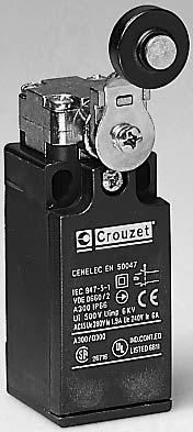
7 Miniature Industrial Limit Switches Series 8 85 / 8 85 EN Conform to the following standards : IEC 56-, IEC , CSA C. No. 4, EN 50047, EN , EN 6004-, NFC 000 class I for 8 85 class II for 8 85 UL 508, VDE 0660/00. Degree of protection : Version : pole Function : Four-terminal double break contact element (form Zb) with positive opening NC contacts. The two moving contacts are electrically isolated from one another. Principle : Independent snap action contact NO + NC Dependent action NO + NC Break Before Make Electrical characteristics Assigned insulation voltage (Ui) : 500 V Thermal rating (Ith) : 0 A Use category : A00 - Q00 AC5 = 6A/50 V -.9 A / 80 V DC = A/4 V Types Thermoplastic case with double insulation and metal actuator head Metal bodies and actuator heads NC + NO Control mechanisms - adjustable actuator heads 4 positions 90 Steel plunger Plunger with steel roller Lever with plastic vertical roller lateral Rotary head, momentary action to right and left () With lever and plastic roller Ø Ø 9 offset 40 offset 5 With adjustable lever and plastic roller Ø to 69.5 With adjustable polyamide rod actuator Flexible metal lever () Action either right or left according to position of head Sequence Independent snap action Dependent action Positive break operation Independent snap action NC + NO Dependent action NC + NO Independent snap action NC + NO Dependent action Ø 50 offset 47 offset 5.5 Ø offset.5 or 45 offset 46 adjustable offset ,8 4,5F 6 mm 0,9 0,8,F 6 mm , 7,8F mm,5 0, 5,6 5,8F mm ,5 5,5Fmm 0 6,5 9,5 F mm ,5 5,5Fmm 0 6,5 9,5 F mm Short circuit test (under IEC ) - Current peak 000 A at 50 V a 0.5 < cos ϕ < Short circuit protection (SCPD) : fuse 0 A gf - Electrical protection by internal earth terminal (8 85) Connections : Saddle washer and M.5 screw Max. wire cross-section : x.5 mm or x.5 mm Connection : For / NPT Approvals : UL listed A00 - Q00 - CSA A00 - Q00 Mechanical characteristics Minimum operating force Minimum total travel force Minimum positive opening force Minimum operating travel Minimum positive opening travel Differential travel Max. total travel N (oz.) N (oz.) N (oz.) mm (in.) mm (in.) mm (in.) mm (in.) Mechanical life (millions of operations) mini. Temperature Use C ( F) limits Stored C ( F) Degree of protection Weight Series 8 85 Series 8 85 g (oz.) g (oz.) 0 (5.) (4.) 5 (88.) 5 (.) 6 (.4).5 (.06) 6 (.4) (-+76) (-40+76) 90 (.) 70 (6) 0 (5.) (4.) 5 (88.) 5 (.) 6 (.4).5 (.06) 6 (.4) (-+76) (-40+76) 00 (.5) 80 (6.) 9 (.7) 0 (5.) 0 (70.5) 5 (.) 6.5 (.47).5 (.06) 6 (.4) (-+76) (-40+76) 00 (.5) 80 (6.) 9 (.7) 0 (5.) 0 (70.5) 5 (.) 6.5 (.47).5 (.06) 6 (.4) (-+76) (-40+76) 05 (.7) 80 (6.) Other information For other contact types and accessories or special modes of operation : please consult us. For dimensions see page /8. Replacement contact block Part number Configurations Function SPDT <STD> SPDT Break before make SPDT Make before break NO DPST - Normally open NC DPST - Normally closed /4 Order/Technical Support Tel: (800) / FAX: (800) /


 8cmN (40inoz) 8cmN (40inoz) (0) 7cmN (5inoz) 7cmN (5inoz) 7cmN")
 75cmN (06inoz) 75cmN (06inoz) 75cmN (06inoz) 75cmN (06inoz) 75cmN (06inoz)")
 -40+80(-40+76) 0 (4.6) 05 (7.")
 0º 75º 5-5+80(-+76) -40+80(-40+76) 5 (5.4) 5 (7.")
 To order, specify : Standard products Standard products, non stocked Part number")
 677-865 / www.crouzet-usa.com /5")
8 F F F F F F F F cmN (40inoz) 8cmN (40inoz) 8cmN (40inoz) 8cmN (40inoz) 8cmN (40inoz) 8cmN (40inoz) 8cmN (40inoz) 8cmN (40inoz) (0) 7cmN (5inoz) 7cmN (5inoz) 7cmN (5inoz) 7cmN (5inoz) 7cmN (5inoz) 7cmN (5inoz) 7cmN (5inoz) 7cmN (5inoz) 4.5 (6) 75cmN (06inoz) 75cmN (06inoz) 75cmN (06inoz) 75cmN (06inoz) 75cmN (06inoz) 75cmN (06inoz) 75cmN (06inoz) 75cmN (06inoz) º 60º 60º 60º 60º 60º 60º 60º 60º 0º 75º (-+76) (-40+76) 0 (4.6) 05 (7.) 0º 75º (-+76) (-40+76) 0 (4.6) 05 (7.) 0º 75º (-+76) (-40+76) 0 (4.6) 05 (7.) 0º 75º (-+76) (-40+76) 0 (4.6) 05 (7.) 0º 75º (-+76) (-40+76) 0 (4.6) 05 (7.) 0º 75º (-+76) (-40+76) 5 (5.4) 5 (7.9) 0º 75º (-+76) (-40+76) 5 (5.4) 5 (7.9) 0º 75º (-+76) (-40+76) 5 (5.4) 5 (7.9) 0º 75º (-+76) (-40+76) 0 (4.6) 00 (7.) To order, specify : Standard products Standard products, non stocked Part number Example : Limit switch Order/Technical Support Tel: (800) / FAX: (800) / /5
 with positive opening NC contacts.")
 : 500 V Thermal rating (Ith) : 0 A Use")
 : fuse 0 A gf - Electrical protection by internal earth terminal Connections : Saddle washer and M.5 screw Max. wire cross-section : x.5 mm or.")
 Ø offset 4.")
9 Industrial Limit Switches Series 8 86 EN 5004 Conform to the following standards : EN 5004, IEC , VDE 0660/00 UL 508, CSA C. No.4 IEC 56-, EN 6004-, NFC 000 class I Degree of protection : Function : Four-terminal double break contact element (form Zb) with positive opening NC contacts. The two moving contacts are electrically isolated from one another. Principle : Independent snap action contact NO + NC Dependent action NO + NC Break before make Electrical characteristics : Assigned insulation voltage (Ui) : 500 V Thermal rating (Ith) : 0 A Use category : A00 - Q00 AC5 = 6A/50 V -.9 A / 80 V DC = A/4 V Short circuit test (under IEC ) - Current peak 000 A at 50 V~0.5 < cos ϕ < Short circuit protection (SCPD) : fuse 0 A gf - Electrical protection by internal earth terminal Connections : Saddle washer and M.5 screw Max. wire cross-section : x.5 mm or.5 mm Connection : / NPT Approvals : UL listed A00 - Q00 - CSA A00 - Q00 Types Dependent action NC + NO Independent snap action NC + NO Control mechanisms - adjustable actuator heads 4 positions 90 Steel plunger Plunger with steel roller Lever with vertical plastic roller lateral Rotary head, momentary action to clockwise and/or anti-clockwise () Ø offset 4.5 With lever and plastic roller With adjustable lever and plastic roller 57 to 7 With adjustable polyamide rod actuator Flexible metal lever Independent snap action Sequence Positive break operation Ø 9 offset 56 offset 50.5 Ø 50 offset 57 Ø offset 6 or 48 offset 49 Ø 50 adjustable offset Dependent action ,7F 6 mm 0,9 0,,4F 6 mm ,4 8F mm,5 0,4 5,6 5,8F mm Mechanical characteristics Minimum operating force Minimum total travel force Minimum positive opening travel Minimum operating travel Minimum positive opening travel Differential travel Max. total travel N (oz.) N (oz.) N (oz.) mm (in.) mm (in.) mm (in.) mm (in.) 0 (5.5) (4.) 5 (88.) 5 (.) 6 (.4).5 (.06) 6 (.4) 0 (5.5) (4.) 5 (88.) 5 (.) 6 (.4).5 (.06) 6 (.4) 9 (.7) 0 (5.) 0 (70.5) 5 (.) 6.5 (.6).5 (.06) 6 (.4) 9 (.7) 0 (5.) 0 (70.5) 5 (.) 6.5 (.6).5 (.06) 6 (.4) Mechanical life (millions of operations) mini Temperature Use C (ºF) -5+80(-+76) -5+80(-+76) -5+80(-+76) -5+80(-+76) limits Stored C (ºF) (-40+76) (-40+76) (-40+76) (-40+76) Degree of protection Weight g (oz.) 05 (0.76) 5 (.) 0 (.8) 5 (.46) () Action either right or left according to position of head Accessories Cover with status indicator 4.0 V a c (supplied loose) 0 V a Replacement contact block Part number Configuration Function SPDT <STD> SPDT Break before make SPDT Make before break NO DPST - Normally open NC DPST - Normally closed 0 6,5 5,5Fmm 0 6,5 9,5 F mm 0 6,5 5,5Fmm 0 6,5 9,5 F mm Other information For other contact types and accessories or special modes of operation : please consult us. For dimensions see page /9. /6 Order/Technical Support Tel: (800) / FAX: (800) /


 8cmN (40inoz) 8cmN (40inoz) (0.")
 7cmN (5inoz) 7cmN (5inoz) 4.5 (5.")
 75cmN (06inoz) 75cmN (06inoz) 75cmN (06inoz) 0º 0º 0º 0º 0º 0º 0º")
 0º 75º 5-5+80(-+76) -40+80(-40+76) 40 () 0º 75º 5-5+80(-+76)")
 0º 75º 5-5+80(-+76) -40+80(-40+76) 65 (.")
 0º 75º 5-5+80(-+76) -40+80(-40+76) 5 (.")

10 F F F F F F F F cmN (40inoz) 8cmN (40inoz) 8cmN (40inoz) 8cmN (40inoz) 8cmN (40inoz) 8cmN (40inoz) 8cmN (40inoz) 8cmN (40inoz) (0.5) 7cmN (5inoz) 7cmN (5inoz) 7cmN (5inoz) 7cmN (5inoz) 7cmN (5inoz) 7cmN (5inoz) 7cmN (5inoz) 7cmN (5inoz) 4.5 (5.8) 75cmN (06inoz) 75cmN (06inoz) 75cmN (06inoz) 75cmN (06inoz) 75cmN (06inoz) 75cmN (06inoz) 75cmN (06inoz) 75cmN (06inoz) 0º 0º 0º 0º 0º 0º 0º 0º 0º 60º 60º 60º 60º 60º 60º 60º 60º 0º 75º (-+76) (-40+76) 40 () 0º 75º (-+76) (-40+76) 40 () 0º 75º (-+76) (-40+76) 40 () 0º 75º (-+76) (-40+76) 40 () 0º 75º (-+76) (-40+76) 65 (.8) 0º 75º (-+76) (-40+76) 65 (.8) 0º 75º (-+76) (-40+76) 65 (.8) 0º 75º (-+76) (-40+76) 60 (.7) 0º 75º (-+76) (-40+76) 5 (.8) Standard products Standard products, non stocked Part number Example : Limit switch Type To order, specify : Accessory Example : Limit switch Cover with status indicator Order/Technical Support Tel: (800) / FAX: (800) / /7
11 Dimensions of 8 85 / 8 85 EN / / / / / / 0.5 Ø 9 Ø.5 5 Ø Ø / NPT / / / / Ø / /5 Ø / / / / Ø / / Ø 50 Ø / / / / / / mm /8 Order/Technical Support Tel: (800) / FAX: (800) /


")
12 Dimensions of 8 86 EN / / / 0/ / NPT / / / / / / / / /6 mm Order/Technical Support Tel: (800) / FAX: (800) / /9
13 Positive Opening Enclosed Limit Switches Series IP 67 Conforms to the following standards: IEC / EN Dimensional conformity: NFC 645 Low voltage directive: 7//EEC and 9/68/EEC Protection from electric shock: NFC 000 or IEC 6056 Class, degree of pollution. Temperature specification: 5 /+70 C /+58 F Degree of protection: IEC 659: /67 NEMA 50: Type,, 4, 6, Function: Contact block is SPDT with double break contacts (form Zb). The NC contacts are positive opening. The NO and NC contacts are electrically isolated. Contact type: Snap action SPDT-DB Brown Black () BN BK () UL cables are 4 black wires numbered -4 with a GRN-YLW ground wire Types Standard Roller turned 90 Standard products.0 meter cable* side exit** Actuator Type Metal plunger Metal roller plunger Metal plunger with threaded barrel Roller plunger - metal with threaded barrel Metal roller lever (operates in both directions) Mechanical characteristics Operating force minimum oz. (N) Total travel force minimum oz. (N) Positive opening force minimum oz. (N) Mechanical life millions of cycles Weight oz. (grams) Contact Sequences Positions given are nominal Zb () BU BK (4) GN-YW Blue Black Green-Yellow Electrical characteristics Assigned impulse voltage (Uimp): 500 V Assigned insulation voltage (Ui): 500 V Thermal rating (Ith): 0 A With standard contacts: Minimum voltage 0V Minimum current 00mA Use categories: Following IEC AC5 = 50V / 6A DC = 4V / 8A Following UL 508 A00 - Q50 Dimensions Ø PRP Ø 8 x 4. r = mm Electrical protection: Under IEC Short-circuit protection (SCPD): 6AgC fuse Electrical protection by internal earth ground Connections: Non-UL: 5 conductor cable H05VF 0.75mm ext. Ø8mm (Black) UL: 5 conductor cable (Grey) Approvals: UL 508, UL 50 Other information (*) For other lengths of cables: modify the last digit of the part number. For example: (**) For different cable outputs: 0 = M connector output =.0 meter cable =.0 meter cable (Standard) =.0 meter cable modify the next to the last digit of the part number.: 0 = Cable side exit (Standard) = Cable bottom exit = Connector side exit = Connector bottom exit For different actuator arms, low voltage / low current contacts / low temperature, special contacts, custom wiring harness, etc., please consult us. 0 /40 Order/Technical Support Tel: (800) / FAX: (800) /
 08 (0) 00 (8) 0 0. (90) 6 (0) 08 (0) 00 (8) 0 0.")
 6 (0) 08 (0) 00 (8) 0 0.")


14 (0) 08 (0) 00 (8) 0 0. (90) 6 (0) 08 (0) 00 (8) (95) 6 (0) 08 (0) 00 (8) 0. (5) in.oz. (5cmN) 5 in.oz. (5cmN) in.oz. (5cmN) 0 0. (90) 6 (0) 08 (0) 00 (8) (0) BK-BK BN-BU BK-BK BN-BU BK-BK BN-BU BK-BK BN-BU BK-BK BN-BU BK-BK BN-BU RP 9,8 TP 8 POP 5,8 OL 4,7 BK-BK BN-BU RP 9,9 TP 8 POP 5,75 OL 4,75 BK-BK BN-BU RP TP 45 4, POP 40,85 OL 9,85 BK-BK BN-BU RP TP 0 7 POP 58 OL 69 BK-BK BN-BU RP 4,8 TP POP 0,8 OL 9, M x Ø.4.6 Ø M x 0.75 Ø Ø 0 Ø 0 mm Standard products Standard products, non stocked To order, please specify: Part number Example : Limit switch ; Cable length = m Type Examples : Limit switch ; cable length = m - Limit switch ; cable length = 6 m Order/Technical Support Tel: (800) / FAX: (800) / /4
15 Compact Limit Switches Series IP 67 Conforms to the following standards IEC / EN Dimensional conformity: NFC 645 Low voltage directive: 7//EEC and 9/68/EEC Electric shock protection: NFC 000 or IEC 6056 class, degree of pollution. Temperature specification: 5 /+70 C /+58 F Degree of protection According to IEC 659: / 67 According to NEMA : Type,, 4, 6, Function Four-terminal double break contact element (form Zb) with positive opening NC contacts. The two moving contacts are electrically isolated from one another. Principle Snap-Action SPDT-DB Brown Black () BN BK () Zb () BU BK (4) GN-YW Blue Black Electrical characteristics Assigned impulse voltage (Uimp): 500 V Assigned insulation voltage (Ui): 500 V Thermal rating (Ith): 0 A With standard contacts: Use category: according to IEC according to UL 508 Electrical protection Integral earth wire Short-circuit protection device: IEC Fuse 6 AgC Minimum voltage 0 V Minimum current 00 ma AC5 = 50 V / 6 A DC = 4 V / 8 A A00 - Q50 Connections 5-core cable HO5VF, 75 mm, ext. Ø 8 mm (non-ul type cable) Approvals UL 508, UL 50 UL cables are 4 black wires numbered -4 with a GRN-YLW ground wire Green-Yellow Types Standard Plunger or roller at 90 Standard Part Number (Cable length =.0 meters, exit: side) Actuator Type Metal plunger Metal roller plunger Metal plunger with threaded barrel Roller plunger - metal with threaded barrel Metal roller lever (operates in both directions) Mechanical characteristics Minimum positive opening force Minimum total travel force Force d ouverture positive minimum Mechanical life Weight Sequences Positions: nominal data Dimensions See sequence diagram RP (*) Other cable lengths: modify the last digit of the part number. For example: 0 = M connector output =.0 meter cable =.0 meter cable (Standard) =.0 meter cable 6 = 6.0 meter cable N (cmn) N (cmn) millions of operations g mm Other information (**) For different cable outputs: modify the next to the last digit of the part number: 0 = Cable side exit (Standard) = Cable bottom exit = Connector side exit = Connector bottom exit For different actuator arms, low voltage / low current contacts / low temperature, special contacts, custom wiring harness, etc., please consult us. /4 Order/Technical Support Tel: (800) / FAX: (800) /
 08 (0) 00 (8) 0 0. (90) 6 (0) 08 (0) 00 (8) 0 0.")
 6 (0) 08 (0) 00 (8) 0 0.")


16 (0) 08 (0) 00 (8) 0 0. (90) 6 (0) 08 (0) 00 (8) (95) 6 (0) 08 (0) 00 (8) 0. (5) in.oz. (5cmN) 5 in.oz. (5cmN) in.oz. (5cmN) 0 0. (90) 6 (0) 08 (0) 00 (8) (0) BK-BK BN-BU BK-BK BN-BU BK-BK BN-BU BK-BK BN-BU BK-BK BN-BU BK-BK BN-BU RP 8.4 TP 6.6 POP 4.4 OL. BK-BK BN-BU RP 0. TP 8.4 POP 6.5 OL 5.5 BK-BK BN-BU RP 4.6 TP 4.7 POP 9.45 OL 8.45 BK-BK BN-BU RP TP 0 7 POP 58 OL 69 BK-BK BN-BU RP.4 TP.6 POP 9.4 OL M x 0.75 Ø Ø Ø Ø Ø 0 M x 0.75 Ø 0 mm Standard products Standard products, non stocked Part number Example: Limit switch Type To order, specify: Examples: Limit switch ; cable length = m - Limit switch ; cable length = 6 m Order/Technical Support Tel: (800) / FAX: (800) / /4
17 Miniature Limit Switches Series Degree of protection : IP 55 or IP 65 - Nema 4,, Version : SPDT - double break Function : Four terminal double break contact element (form Za). The contacts must be of the same polarity. Layout : A- For 8 80 B - Other types Electrical characteristics : Assigned insulation voltage (Ui): 50 V Current Rating Assigned working currents (Ie): 5 A Operating curve : Type Plug in version Features Top mounted plunger Top mounted plunger with threaded barrel Top mounted roller plunger with threaded barrel Side rotary head - momentary Top mounted roller plunger Flexible metal spring Fiberglass Rod Mechanical Characteristics Operating force Total travel force - min. Operating Travel - min Movement differential Total travel - max Mechanical life Operating temp. Degree of protection Weight Accessories for Sold separately N (oz) N (oz) mm (in) mm (in) mm (in) operation C (F ) grams (oz) Resistive circuit Inductive circuit { L = 5 ms R cos ϕ = 0.8 * Lever settings or positions dictated by direction in which block is fitted Adjustable in 6 steps Adjustable in 90 steps Dimensions Axis of head rotation 5 (.98) 5.5 () Connections : - Plug in : Screw terminals - max. wire section.5 mm - Non Plug in : Solder tags (able to accept.8 x 0.5 mm clips). Contact Crouzet for part # and availability Connection : For N 9 sealing gland, 5. dia.,.4 pitch metal plastic 60.5 (.8).5 (.85) (.4) 9 (.75) 7 (.06) (.87) Ø8 (.5) (.5) x04. (.08x.7) For N 9 sealing gland Approvals: UL cul mm(in) Other information For other accessories and special contacts, or special modes of operation, please contact factory. Low temperature version available. /44 Order/Technical Support Tel: (800) / FAX: (800) /
 0 7-0 to 70 (-4 to 58) IP 55 50 (.8) 0 (5.) (77.6).5 (.06) 0.4 (.06) 5 (.")
 0 7-0 to 70 (-4 to 58) IP 55 57 () 7 NcM 0 in.oz.")
 5 (.) 0 7-0 to 70 (-4 to 58) IP 65 50 (.8). (4.).5 (8.")
 8 0 0 7-0 to70 (4 to 58) IP65 60 (.")
.")
 79 5 Adjustable Straight roller lever /6 7/8 (8 7mm) Dimensions 8 800 8 80")
 8 80 8 80 8 805 M6x 7maxi (.8) 4 (.65) 5 /6 \" () () 7/8 \" (7.5) / \" M5x5 (.")
 56 (.) 50. (.98). (.48) 6.")
 (8 7) /6 \" 7 /8 () 4 \" (6) mm(in) Standard products Standard products, non")
18 (5.) (77.6).5 (.06) 0.4 (.06) 5 (.) to 70 (-4 to 58) IP (.8) 0 (5.) (77.6).5 (.06) 0.4 (.06) 5 (.) to 70 (- 4 to 58) IP () " 0 (5.) (77.6).5 (.06) 0.4 (.06) 5 (.) to 70 (-4 to 58) IP () 7 NcM 0 in.oz. 8 NcM 5 in.oz to 70 (-4 to 58) IP (.) 0 (5.) (77.6).5 (.06) 0.6 (.4) 5 (.) to 70 (-4 to 58) IP (.8). (4.).5 (8.8) to 70 (4 to 58) IP65 50 (.65).8 (.8) (7.05) to70 (4 to 58) IP65 60 (.) Accessories for Sold separately Galvanized, passivated steel roller arm. Thermoplastic roller. Lever supplied with nut, washer and locating block (loose).* Bent roller lever R: /8 (0mm) Straight roller lever R:/8 (0mm) 79 5 Adjustable Straight roller lever /6 7/8 (8 7mm) Dimensions Ø5 (.59) Ø8 (.5). (.7) () " (Ø8) M6x Ø 5 /6 " (7 max.) (4) 5 /8 " Øx.4 (.4x.) M6x 7maxi (.8) 4 (.65) 5 /6 " () () 7/8 " (7.5) / " M5x5 (.5) 7/8 " (Øx.4) Ø 7 /6 " x /8 " (Ø5) (50).75" max. 7 /8 " Ø0x6 (.79x.4) 56 (.) 50. (.98). (.48) 6. (.4) 6. (.04) (6.) (6.) /6 " / " (08) 0 " (0) 0 " R0 (.8) (8 7) /6 " 7 /8 () 4 " (6) mm(in) Standard products Standard products, non stocked Example: Part number Part number To order, specify: Accessory Example: Actuator Order/Technical Support Tel: (800) / FAX: (800) / /45

 8 7-8 7 : 5 A 50 V 8 7 : 5 A 50 V Thermal rating")
 force Minimum total travel N (oz.")
 Mechanical life Temperature limits Degree of protection Weight Dimensions Operations C ( F) C ( F) g (oz.")
 5 (88.).5 (.059) 0. (.008) 4 (.57) 0 6-5 + 70 IP 56 70 (.")


19 Automotive Limit Switches Series 8 7 / 8 7 / 8 7 Conform to the following standards : IEC EN NFC 000 : Class I Class III Degree of protection : IP 56 - depending on type Version : pole Function : -terminal single break twoway contact element (form C: inverter). Principle : Electrical characteristics : Assigned operating current (Ie) : 5 A 50 V 8 7 : 5 A 50 V Thermal rating (Ith) : A Operating curve : Operations Types Control mechanisms Top-mounted plunger Top-mounted plunger with roller Mechanical characteristics Minimum operating N (oz.) force Minimum total travel N (oz.) force Minimum operating travel mm (in.) Differential travel mm (in.) Max. total travel mm (in.) Mechanical life Temperature limits Degree of protection Weight Dimensions Operations C ( F) C ( F) g (oz.) mm (5) 5 (.4) (.079) 0. (.008) 6 (.6) (.9) (5) 5 (.4) (.079) 0. (.008) 6 (.6) (.9) (.) 5 (88.).5 (.059) 0. (.008) 4 (.57) IP (.5) Resistive circuit c L = 5 ms Inductive circuit R { a cos ϕ = 0.8 A Connections : PVC cable (A05 - VV - F) 0.50 m long conductors cross-section 0.75 mm Sheathed, ext. Ø : 7.6 mm Core connections : : black (common) : brown (NC) 4 : blue (NO) Electrical protection : Earthing terminal for version 8 7 and 8 7. Approvals : CSA A00. Other information For other versions, functions and special contacts or special modes of operation : please consult us. / meter cable Standard products, non stocked To order, specify : meter cable meter cable Type Example : Limit switch /46 Order/Technical Support Tel: (800) / FAX: (800) /
. Function : Single break two-way contact element (Form C : inverter).")
 Mechanical characteristics Minimum operating N (oz.) force Minimum total travel N (oz.")
20 Automotive Limit Switch Series Conform to the following standards : IEC NFC 000 class I : plunger actuated via earthed metal part or an insulating device providing additional insulation. Version : pole Degree of protection : /67 Resistant to hydrocarbons and saline mist (400 hours). Function : Single break two-way contact element (Form C : inverter). Components : Materials Casing : thermoplastic polyester Plunger : stainless steel Contact : Agcdo - AgNi (gold) Nuts : galvanized steel Sealing Silicon and teflon seals PU resin. Principle : Types Standard Two-level Control mechanism Top-mounted plunger Function Form C (SPDT) Mechanical characteristics Minimum operating N (oz.) force Minimum total travel N (oz.) force Minimum operating travel mm (in.) Differential travel mm (in.) Max. total travel mm (in.) Mechanical life* Operations Temperature limits C (ºF) Degree of protection Weight g (oz.) * For operating travel of 4 mm. Dimensions Direction of operation C 0 (5.5) 5 (5) (0.08) 0. (.004) 4.5 (.77) (-40+85) / C 0 (5.5) 5 (5) (0.08) 0. (.004) 4.5 (.77) (-40+85) / Electrical characteristics : Standard : 8 A 50 V a : operations 00 ma 4 V c relay load L/R = ms 0 7 operations Two-level : ma 4 V : 0 7 operations 00 ma 4 V c relay load L/R = ms 5 x 0 6 operations 5 A 50 V a : 0,000 operations The two-level type is designed to operate both on two-level ( ma 4 V minimum) and medium current (5 A maximum) circuits. However, a given product can only switch a single type of circuit throughout its life. Operating travel Total travel Connections : x 0.75 mm PVC cables m long Conforms to NFR 44/45. Core connections : = black (common) = gray (NC) 4 = blue (NO) x 0.75 mm cable 0.50 m long across flats Mounting : Max. tightening torque : 9 Nm. Other information To order, specify : For other versions, functions and special contacts or special modes of operation : please consult us series.) Model.) Contact Configuration.) Output 4.) Length A (SPNO) W (Wires) 0.5 (/ meter) B (SPNC) C (Cable).0 ( meter) C (SPDT).0 ( meter) Order/Technical Support Tel: (800) / FAX: (800) / /47
21 Sealed Limit Switches Telescopic-Actuator Series 8 58 Conforms to the following standards : NFC 000 class II - NFC 000 Degree of protection : IP 67 Contact type : Three terminal single break contact element (Form C: SPDT) Layout : Electrical characteristics : Assigned working currents (Ie): standard 0 A - 50 V~ low current 0. A - 50 V~ Electrical endurance : Standard : 0 A - 50 V : operations 5 A - 50 V : operations Low current : Designed for use from to 00 ma at 4 to 0 volts. In these conditions, the electrical endurance exceeds the mechanical life. Connections : Flexible leads x mm. Length 0.50 m Cable x0,75 mm. Length 0.50 m Core connections: : black : brown 4: blue Versions Features Standard Low current Operating devices Telescopic top-mounted plunger Plunger with axial roller - standard Plunger roller at 90 (G 90) - Consult Factory Contact Type Form C SPDT Mechanical characteristics Minimum operating force Minimum total travel force Movement differential Minimum operating travel Total travel max. Mechanical life Temperature limits Degree of protection Weight Connections Flexible leads Lead position - right (D) Lead position - left (G) Cable Output on left * Rating restricted to 8A Dimensions M0x0.75 Ø7 (.8) R0 spherical Nuts 4 across flats Depth Ø (.47) N (oz) N (oz) mm (in) mm (in) mm (in) Operations C ( F) g (oz) mm(in) 7.4 (.08). (.047) 5.5 max 8.7 (74) 6 (.4) 5 () 4 max (.55) Other information For other accessories and special contacts, or special modes of operation, please consult factory. /48 Order/Technical Support Tel: (800) / FAX: (800) /
 0 (70.5) (.04).5 (.) 5 (.) 0 5-0 to 85 (-4 to 85) IP 67 45 (.6) R L C* 5 (7.6) 0 (70.5) (.04).5 (.) 5 (.) 0 5-0 to 85 (-4 to 85) IP 67 45 (.6) R L C 4 8 58 Ø8x (.5x.")
22 S S B B C C C C 5 (7.6) 0 (70.5) (.04).5 (.) 5.5 (.) to 85 (-4 to 85) IP (.4) R L C* 5 (7.6) 0 (70.5) (.04).5 (.) 5.5 (.) to 85 (-4 to 85) IP (.4) R L C 5 (7.6) 0 (70.5) (.04).5 (.) 5 (.) to 85 (-4 to 85) IP (.6) R L C* 5 (7.6) 0 (70.5) (.04).5 (.) 5 (.) to 85 (-4 to 85) IP (.6) R L C Ø8x (.5x.) Roller either in line (standard) or at 90 Nuts 4 across flats Depth M0x (.08) 6.5 (.04).5 max (.06) 5.5 max 6.5 max (.6) 6 (.4) 5 () 4 max (.55) To order, please specify : Switch Type Current Level Contacts S - 0A C B - <.A Example : 8580 S C C 4 Outputs R - Right (flexible wires) L- Left (flexible wires) C - Cable left output only Lead Length / meter - meter - meter Order/Technical Support Tel: (800) / FAX: (800) / /49
23 Door Interlock Switches Series 8 5 / 8 58 General Specifications : Operation To defeat the switch Depress the plunger and turn it a quarter of a turn. To reset the switch to rest position depress the plunger. Components Bracket Zinc plated mild steel Plunger Stainless steel Switch 8 5, , 8 58, 8, 8 Types Features Operating force min. Movement differential Total travel max. Tripping point min. Mechanical life Weight Operating temperature Contact Configuration - SPDT Connections Screw Solder (.0 " Quick connect also for 8 58) /4" Quick connects /6" Quick connects N (oz) mm (in) mm (in) mm (in) Operations grams (oz) ºC (ºF) Layout Current Ratings Amps Amps Other current ratings are available For low current applications, gold contacts are available Approvals: Please consult us. Other information Standard products normally stocked Catalog products, produced to order /50 Order/Technical Support Tel: (800) / FAX: (800) /
.5 (.4) 0 7 0 7 0 7 0 7 0 6 40 (.4) 55 (.94) 0 (.70) (.8) 50 (.76) C C C C C N/A Dimensions N/A N/A N/A N/A N/A N/A N/A 5 6 8 5 XM.59 (5).8 (4.5).49 (.5).6 (6).6 (55) X Ø.")
 (8.5)")
24 Pole Poles Pole Poles Poles 0 (05) 0 (05) 6 (.) 8 (8.) 0 (70.4) (.04) (.04).7 (.07).7 (.07) (.04) 6 (.4) 6 (.4) 6 (.4) 6 (.4) 7.5 (.9) 4 (.6) 4 (.6).5 (.0).5 (.0).5 (.4) (.4) 55 (.94) 0 (.70) (.8) 50 (.76) C C C C C N/A Dimensions N/A N/A N/A N/A N/A N/A N/A XM.59 (5).8 (4.5).49 (.5).6 (6).6 (55) X Ø. ( X Ø.) (). (5.6) (5.5).5.5 (0) (8.5) (85). XØ. (XØ.) ().6.57 (40) A.6.4 (6) (0) Ø. (Ø.8) XM.79 (0).6 (6) (4.).7.95 (4) Ø.4 (Ø6) (4.5).8 mm (in) To order, please specify: Example : 8580 C DL Switch Type Configuration Connections C Order/Technical Support Tel: (800) / FAX: (800) / /5
25 Miniature Limit Switches with Manual Reset Series / EN Conform to the following standards : IEC 56-, IEC , CSA C. N 4 EN 50047, EN 6004-, EN NFC 000 class II for class I for UL 508, VDE 0660/00 Degree of protection : Function : Four-terminal double break contact element (form Zb) with positive opening NC contacts. The two moving contacts are electrically isolated from one another. Principle : Dependent action contact ( NC + NO) Break before make Electrical characteristics : Assigned insulation voltage (Ui) : Thermal rating (Ith) : 0 A Use category : A00 - Q00 AC5 = 6A/50 V -.9 A / 80 V DC = A/4 V After actuation, the safety contact remains locked open in position "NC". It is unlocked by pressing the reset button. 500 V Short circuit test (under IEC ) - Current peak 000 A at 50 V~0.5 < cos ϕ < Short circuit protection (SCPD) : fuse 0 A gf - Electrical protection by internal earth terminal (8 850) Connections : Saddle washer and M.5 screw Max. wire cross-section : x.5 mm or x.5 mm Connection : For No. sealing gland Approvals : Slow break NC + NO version UL / CSA : please consult us. Part number Thermoplastic case and metal head Metal bodies and actuator heads Ø 50 Special option - configuration EN Control mechanisms - adjustable actuator heads 4 positions 90 Steel plunger Plunger with steel roller Lever with vertical plastic roller lateral Rotary head, momentary action to right and left () With lever and plastic roller With adjustable lever and plastic roller Sequence Positive break operation Mechanical characteristics Minimum operating force Minimum total travel force Minimum positive operating force Minimum operating travel Minimum positive opening travel Differential travel Max. total travel Mechanical life Temperature Use limits Stored Degree of protection Weight (plastic/metal) () Action either right or left according to position of head Dimensions Ø 9 Ø Ø 50 Ø Ø 9 offset or 5 Ø offset.5 or 40 offset 47 Ø 50 offset 5.5 Ø offset.5 or 45 offset 46 Ø 50 adjustable offset 5.5 to 69.5 Dependent action mm Ø N - (cmn) N - (cmn) N - (cmn) mm - ( ) mm - ( ) mm - ( ) mm - ( ) 0 6 operations min. C C g Ø /5 Other information Standard products Standard products, non stocked To order, specify : Part number Example : Limit switch with manual reset Order/Technical Support Tel: (800) / FAX: (800) /
 8 857 5 (Ø50) 8 856 (Ø) 8 856 5 (Ø50) 8 857 (Ø9) 8")
 8 856 7 (Ø50) 8 857 8 (Ø50) 8 856 8 (Ø50) 0,8,F 6")


 (7) (75) (0) (46) (0) (75) -0 +80-40")
 (0) (75) -0 +80-40 +80 0/0 8 856 / - 8 857 / 8 856-8 857")


26 (Ø) (Ø50) (Ø) (Ø50) (Ø9) (Ø50) (Ø9) (Ø50) (Ø) (Ø50) (Ø) (Ø50) (Ø50) (Ø50) 0,8,F 6 mm 0, 5,4 5,6F mm 0 6,5 9,5 F mm 0 6,5 9,5 F mm F F / / / /40 (8) (7) (75) (0) (46) (0) (75) /70 (8) (7) (75) (0) (46) (0) (75) /70 (8) (7) (0) (0) (75) /00 (8) (7) (0) (0) (75) / / / Ø / Ø 50 Ø Ø Ø Ø Ø Ø Ø / / Order/Technical Support Tel: (800) / FAX: (800) / /5
 Wired (0.8 mm - 0.50 m long) Epoxy resin coating Soldered Characteristics Min. current Nominal current Resistive Lamp Lamp Resistive Inductive L/R = 0.005 s Resistive Inductive - cos ϕ 0.")
 Voltage drop at A () Operating temperature Resistance to shock () Resistance to vibration () MΩ V C g/ms g/hz 00 0.")
27 Hermetically Sealed Limit Switches Hermetically sealed microswitch Part # Without accessories (basic cell C) Solder Inert gas filling Solder Compressed glass seal Connections (consult factory) Wired (0.8 mm m long) Epoxy resin coating Soldered Characteristics Min. current Nominal current Resistive Lamp Lamp Resistive Inductive L/R = s Resistive Inductive - cos ϕ 0.8 Service life at nominal current () - operations Dielectric strength between connections and ground Rigidity between connections 5 V c 48 V c () 5 V Hz 0 V c () 0 V c () 0 V c () 0 V a 0 V a ma A A A A A A A min V V , Insulation resistance (at 500 Vdc) Voltage drop at A () Operating temperature Resistance to shock () Resistance to vibration () MΩ V C g/ms g/hz / 80/0 000 () For a service life of 00,000 operations - Permissible current 4A inductive 7 A resistive for normally open or normally closed. () On soldered connections - For wired connections add 0. V per metre. () Value for microswitch without control button A B A- Parallel to the axis (//) B - Perpendicular to the axis ( ) Dimensions Add the dimensions of the various connections for the total dimensions ( indicates the direction of the wires) 07 - Stop washer thick - Locating pin - h. 0 - Nut h.5-5 across flat Panel cut-out Part numbers Wire 0.8 mm 0.50 m long perpendicular With single-pole roller plunger Characteristics Max operating force Min. release force Permitted overtravel force Positive overtravel stop Max. pre-travel Max. differential travel Min. overtravel Resistance to shocks Resistance to vibrations Weight (without wires) Service life (operations - min) with parallel wires N N N mm mm mm g/ms g/hz g / 50/ ,000 Ø. Ø 4.. To order, specify : Standard products, non stocked Part number Example : Hermetically sealed limit switch /54 Order/Technical Support Tel: (800) / FAX: (800) /
 - operations Operating temperature Max. operating force Min. release force Max. pre-travel Max. differential travel Min.")

28 Waterproof Limit Switches Series 8 4 Standard sensitive microswitch (55 C +50 C) Without accessories Characteristics Nominal current Resistive Inductive L/R = s 0 V c 0 V c 0 V a 0 V c 0 V a Service life at nominal current () - operations Operating temperature Max. operating force Min. release force Max. pre-travel Max. differential travel Min. overtravel Weight A A A A A C N N mm mm mm g , Connections Solder tags () Value for microswitch without control button 07 - Stop washer width Locating pin 7 - Free position 8 - Nuts h..5-5 across flat 0 - Nuts h..5 and 6-5 across flat - Nuts h. and 6 - across flat - Roller Ø width 0 - Pin h Ø Ø 6 Ø. 0 Panel cut-out M x Ø Dimensions mm.5 0 Ø Ø.5 0 M x Ø 6. Part numbers pole With plunger With plunger and roller Output with perpendicular wires Characteristics Max. operating force Min. release force Max. total travel force Max. pre-travel Max. differential travel Min. overtravel Weight (with wires) General characteristics Nominal current Resistive Inductive L/R = s Service life at nominal current (min. operations) Dielectric strength between connections and ground Dielectric strength between connections Insulation resistance (at 500 Vdc) Voltage drop at A* Operating temperature Resistance to shock Resistance to vibration * For flying leads, add 0. V/metre. To order, specify : N N N mm mm mm g 0 V c 0 V c 0 V a 0 V c 0 V a A 0.0 A 4 A A A ,000 V 500 V 000 MΩ 00 V 0.06 C g/ms 50/ g/hz 0/0 000 Standard products, non stocked Part number Example : Waterproof limit switch Order/Technical Support Tel: (800) / FAX: (800) / /55

 : 500V Thermal")
29 7.5 Cable Pull Limit Switches Series 8 86 / Conforms to the following standards: EN IEC VDE 0660/ UL UL CSA C. No4 NFC class - EN 48 - Machine Directive 89/9/CEE Degree of Protection : Function : Four separate terminals with two separate NC switching elements with positive opening contacts. One set works in the cable break mode and the other works in the cable pull mode. Both elements are electrically isolated from one another. Layout : Cable attached with tension Cable Pull Mode Cable Break Mode Part Numbers Metric No /" NPT Electrical characteristics : Assigned insulation voltage (Ui) : 500V Thermal rating (Ith) : 0 A Use category : A00 - Q00 AC5 = 6A/50V -.9 A/80V DC = A/4V Short circuit test (under IEC sec. 8..4) - Current peak 00 A at 50V`0.5<cos <0.7 - Short circuit protection (SCPD) : fuse 0 A gf - Electrical protection by internal earth ground Connections : Saddle washer and M.5 screw Max. wire cross section : x.5 mm or x.5 mm Connection : For No or /" NPT sealing gland Approvals : Pending 4 Mechanical Characteristics: Minimum Operating Force cmn 85 Minimum Operating Distance mm 4 Movement Differential mm Maximum Total Travel mm 8 Mechanical Life operations x0 7 Operating Temperature C -5 to +70 Storage Temperature C -40 to +70 Mounting Characteristics : Maximum Length of Cable meters 6 Dimensions : 6 ±0.4 mm 67 Typical Mounting: The cable is to be tightened until the head is extended with the slot below the E-ring visible. This sets the switch. Maximum cable length = 6 meters 5 0 ±0.4 ± ±0. 5. ±0.. Lock Nut. Eyelet Bolt. Cable through eyelet bolt. 4. Cable clamps 5. Cable - red PVC (red is internation color for safety).5 N PG OR / "NPT Standard products available in-stock in normal quantities Catalog products produced to order /56 Order/Technical Support Tel: (800) / FAX: (800) /

 677-865 / www.")
30 Safety (Security) Limit Switches Order/Technical Support Tel: (800) / FAX: (800) / /57


31 Miniature Plastic Key Lock Limit Switches Series / 8 89 IP 67 Key-operated safety interlock switches for monitoring the moving cover Plastic bodies and heads Heads have 4 possible positions Positive opening contacts General characteristics Environment Conforming to standards Certifications Protective treatment Temperature Vibration resistance Shock resistance Degree of protection Cable entry Products Machine assemblies Use Stored Electrical characteristics Assigned working characteristics Assigned insulation voltage Assigned impulse voltage Thermal rating Electric shock protection IEC , EN , UL 508, CSA C- no.4, JIS C450 (See P. / and /) IEC 04-, EN , EN 088, EN 9 UL, CSA In normal operation: "TC" -5 C, +70 C -40 C, +70 C 5 gn (0 500 Hz) according to IEC gn (duration ms) according to IEC 8--7 IP 67 according to IEC 59 and IEC Cable gland AC 5 A 00 Ue = 40 V, Ie = A or Ue = 0 V, Ie = 6 A DC Q 00 Ue = 50 V, Ie = 0.7 A or Ue = 5 V, Ie = 0.55 A Ui = 500 V according to IEC Ui = 00 V according to UL 508, CSA C- no. 4 Uimp = 6 KV acc. to IEC Ithe = 0 A according to IEC Class according to IEC 56 Part numbers Type of contact NC+NO -pole contact NC+NO break before make, slow action NC+NC -pole contact NC+NC, slow action NC+NO+NO -pole contact NC+NO+NO ( NO bbm) + slow action NC+NC+NO -pole contact NC+NC+NO (NO bbm) + slow action Additional characteristics Maximum actuation speed Minimum actuation speed Resistance to removal of key Mechanical life Maximum operating frequency Minimum positive opening force Pg cable entry according to NFC Thermal rating (Ith) Assigned insulation voltage (Ui) m/s 0.0 m/s 0 N million operating cycles 600 operating cycles per hour 5 N 0 A 500 V m/s 0.0 m/s 0 N million operating cycles 600 operating cycles per hour 5 N 0 A 500 V Resistance between terminals Short-circuit protection Connection Electrical life 0 mω according to IEC Cartridge fuse 0 A gg (gl) Screw clamp terminals Clamping capacity min. x 0.5 mm, max..5 mm with or without ferrule According to IEC appendix C Weight Accessories Straight key Key with wide fixing bar 0.0 kg 0.60 kg Short key with wide fixing bar Angled key Flexible key Standard products Standard products, non stocked To order, specify: Part number Accessory Example: Safety limit switch Straight key Accessory Example: Straight key /58 Order/Technical Support Tel: (800) / FAX: (800) /
32 Dimensions threaded hole for cable gland = 0/ = 0 0 slots Ø 4. x 8. fixing centres ; holes Ø 4. fixing centres 0 threaded holes for cable gland slots Ø 5. x. 0/ slots Ø 4. x 8. fixing centres ; holes Ø 4. fixing centres 0 Accessories / slots Ø 4.7 x == 40 = = 6 slots Ø 4.7 x 0 L 55 Types Dimension L (mm) slot Ø4.7 x = = slots Ø4.7 x Operating radius / 585 R = 500 R = min. radius R = 00 R = 500 R = min. radius R = d d Types Dimension d (mm) R = 500 R = min. radius R = 00 R = 50 R = min. radius R = Other information Order/Technical Support Tel: (800) / FAX: (800) / /59

33 Solenoid Operated Plastic Key Lock Limit Switches Series 8 89 IP 67 Monitoring of the moving cover for machines with a stopping time which is greater than the time taken to access the danger zone Locked by removing the voltage, unlocked by applying voltage to the electromagnet Plastic bodies and heads Heads have 4 possible positions Positive opening contacts General characteristics Environment Conforming to standards Certifications Protective treatment Temperature Vibration resistance Shock resistance Degree of protection Cable entry Products Machine assemblies Use Stored Electrical characteristics Assigned working characteristics Assigned insulation voltage Assigned impulse voltage Thermal rating Electric shock protection IEC , EN , UL 508, CSA C- no. 4, JIS C450 IEC 04-, EN , EN 088, EN 9 UL, CSA In normal operation: "TC" -5 C, +70 C -40 C, +70 C 5 gn (0 500 Hz) according to IEC gn (duration ms) according to IEC 8--7 IP 67 according to IEC 59 and IEC One entry per cable gland AC 5 B00 Ue = 40 V, Ie =.5 A or Ue = 0 V, Ie = A DC Q00 Ue = 50 V, Ie = 0.7 A or Ue = 5 V, Ie = 0.55 A Ui = 500 V according to IEC Ui = 00 V according to UL 508, CSA C- no. 4 Uimp = 4 KV acc. to IEC Ithe = 6 A according to IEC Class according to IEC 56 Part numbers Type of contact NC+NO -pole contact NC+NO break before make, slow action Additional characteristics Electromagnet supply voltage (50/60 Hz in a) Maximum actuation speed Minimum actuation speed Resistance to removal of key Mechanical life Maximum operating frequency Minimum positive opening force Pg cable entry according to NFC Weight Accessories Straight key Key with wide fixing bar V a/c 0 V a/c 0 V a/c 0.5 m/s 0.0 m/s 500 N million operating cycles 600 operating cycles per hour 5 N 0.60 kg Resistance between terminals Short-circuit protection 0 mω according to IEC Cartridge fuse 0 A gg (gl) Short key with wide fixing bar Connection Screw clamp terminals Clamping capacity min. x 0.5 mm, max..5 mm with or without ferrule Angled key Electrical life According to IEC appendix C Flexible key Standard products Standard products, non stocked To order, specify: Part number Accessory Example: Safety limit switch Angled key Part number Accessory Example: Safety limit switch Straight key /60 Order/Technical Support Tel: (800) / FAX: (800) /
34 Locking / unlocking using an electromagnet Type 8 89 safety switches are fitted with an electromagnet for locking/unlocking the guard. With the guard locked, the force required to remove the key is 50 dan. In addition to the -pole contact element actuated by the key, type 8 89 limit switches also have a positive break type NC contact element, actuated by the electromagnet. The NC contact is integrated in the machine safety circuit. Unlocking using a special tool UNLOCK Type 8 89 safety switches are supplied with a tool () which can be used to unlock the moving guard, bypassing the electromagnet. Unlocking using a tool is recommended in the following cases: machine maintenance (if the tool is in the UNLOCK position and then removed, this will prevent the machine from restarting accidentally, therefore ensuring the safety of maintenance personnel), mains failure, problem with unlocking (locking cannot be released: fail-safe condition). Unlocking by applying voltage to the electromagnet always takes priority over unlocking using a tool. The NC contact is integrated in the machine safety circuit. Power supply for the electromagnet on 8 89 The electromagnet for type 8 89 safety switches is supplied by an electronic circuit which increases its service life. As the 4 V version is protected by a bridge rectifier, an A.C. or D.C. supply can be used. Dimensions 8 89 The 0 V and 0 V versions are A.C. only. It is also protected against voltage surges. Category connection according to EN 954- Examples of wiring diagrams with a fuse to provide protection against short-circuits in the cable or tampering. Locking by removal of voltage F 0 5 Electromagnet () () / 4 0 slots Ø 4. x 8. fixing centres ; holes Ø 4. fixing centres 0 E E O I X threaded hole for cable gland X () Auxiliary contact E-E: Power supply for electromagnet : Safety contact for redundancy or signalling M Other information For accessory dimensions, see page /5. Order/Technical Support Tel: (800) / FAX: (800) / /6

35 Industrial Metal Key Lock Limit Switches Series IP 67 Spade terminal safety interlock switch for monitoring the moving cover Metal bodies and heads Heads have 4 possible positions Positive opening contacts General characteristics Environment Conforming to standards Certifications Protective treatment Temperature Vibration resistance Shock resistance Degree of protection Cable entry Products Machine assemblies Use Stored Electrical characteristics Assigned working characteristics Assigned insulation voltage Assigned impulse voltage Thermal rating Electric shock protection IEC , EN , UL 508, CSA C- no.4, JIS C450 IEC 04-, EN , EN 088, EN 9 UL, CSA In normal operation: "TC" -5 C, +70 C -40 C, +70 C 5 gn (0 500 Hz) according to IEC gn (duration ms) according to IEC 8--7 IP 67 according to IEC 59 and IEC One threaded entry for cable gland AC 5 A 00 Ue = 40 V, Ie = A or Ue = 0 V, Ie = 6 A DC Q 00 Ue = 50 V, Ie = 0.7 A or Ue = 5 V, Ie = 0.55 A Ui = 500 V according to IEC Ui = 00 V according to UL 508, CSA C- no.4 Uimp = 6 KV according to IEC Ithe = 0 A according to IEC Class according to IEC 56 Part numbers Type of contact NC+NO+NO -pole contact NC+NO+NO ( NO bbm) slow action Additional characteristics Maximum actuation speed Minimum actuation speed Resistance to removal of key Mechanical life Maximum operating frequency Minimum positive opening force Cable entry (DIN Pg.5 cable gland ) according to NFC Weight Accessories Straight key Key with wide fixing bar m/s 0.0 m/s 0 N > million operating cycles 600 operating cycles per hour 0 N 0.60 kg Resistance between terminals Short-circuit protection 0 mω according to IEC Cartridge fuse 0 A gg (gl) Flexible key Connection Electrical life Screw clamp terminals Clamping capacity min. x 0.5 mm, max..5 mm with or without ferrule According to IEC appendix C Standard products Standard products, non stocked To order, specify: Part number Accessory Example: Safety limit switch Wide key Accessory Example: Flexible key /6 Order/Technical Support Tel: (800) / FAX: (800) /
36 Dimensions mm threaded hole for cable gland slots Ø 7. x 5. Accessories slots Ø 5. x 0 == 5 0 = = 5 5 = = 5 slots Ø 4.7 x Operating radius R = 000 R = min. radius R = 000 R = 000 R = min. radius R = R = R = R = min. radius 78 Other information Order/Technical Support Tel: (800) / FAX: (800) / /6

37 Solenoid Operated Metal Key Lock Limit Switches Series Monitoring of the moving cover for machines with a stopping time which is greater than the time taken to access the danger zone Locked by removing the voltage, unlocked by applying voltage to the electromagnet Metal bodies and heads Heads have 4 possible positions Positive opening contacts General characteristics Environment Conforming to standards Certifications Protective treatment Temperature Vibration resistance Shock resistance Degree of protection Cable entry Products Machine assemblies Use Stored IEC , EN , UL 508, CSA C- no.4, JIS C450 (See P. /4) IEC 04-, EN , EN 088, EN 9 UL, CSA In normal operation: "TC" -5 C, +70 C -40 C, +70 C 5 gn (0 500 Hz) according to IEC gn (duration ms) according to IEC 8--7 IP 67 according to IEC 59 and IEC Threaded entry for cable gland Part numbers Type of contact NC+NO+NO -pole contact NC+NO+NO ( NO bbm) + slow action NC+NC+NO -pole contact NC+NC+NO (NO bbm) slow action Additional characteristics Electromagnet supply voltage (50 / 60 Hz in a) Maximum actuation speed Minimum actuation speed Resistance to removal of key Mechanical life Maximum operating frequency V a/c 0 V a/c 0 V a/c 0.5 m/s 0.0 m/s 000 N > million operating cycles 600 operating cycles per hour Electrical characteristics Assigned working characteristics Assigned insulation voltage Assigned impulse voltage Thermal rating Electric shock protection Resistance between terminals Short-circuit protection Connection Electrical life Dimensions mm AC 5 B00 Ue = 40 V, Ie =.5 A or Ue = 0 V, Ie = A DC Q00 Ue = 50 V, Ie = 0.7 A or Ue = 5 V, Ie = 0.55 A Ui = 500 V according to IEC Ui = 00 V according to UL 508, CSA C- no. 4 Uimp = 4 KV according to IEC Ithe = 6 A according to IEC Class according to IEC 56 0 mω according to IEC Cartridge fuse 0 A gg (gl) Screw clamp terminals Clamping capacity min. x 0.5 mm, max..5 mm with or without ferrule According to IEC appendix C Minimum positive opening force Cable entries Pg according to NFC Weight.40 kg Electromagnet characteristics Load factor Voltage limits Service life Consumption Accessories Straight key Inrush Sealed Indicator characteristics Assigned insulation voltage according to IEC Current consumption Assigned working voltage a or c Voltage limits a or c (including ripple) Service life Protection against voltage surges 0 N 00% -0% ; +0 % 0,000 hours 0 VA 0 VA 50 V 50 V 50 V 7 ma 7 ma 7 ma 4 V 0 / 40 V 0 / 40 V 0 5 V V V 00,000 hrs 00,000 hrs 00,000 hrs yes yes yes slots Ø 7. x 5. Wide key threaded hole for cable gland Flexible key Standard products Standard products, non stocked To order, specify: Part number Accessory Example: Safety limit switch Wide key Part number Accessory Example: Safety limit switch Straight key /64 Order/Technical Support Tel: (800) / FAX: (800) /
38 Locking / unlocking using an electromagnet Type safety switches are fitted with an electromagnet for locking/unlocking the guard. With the guard locked, the force required to remove the key is 00 dan. In addition to the -pole contact element actuated by the key, limit switches also have a positive break type NC + NO contact element, actuated by the electromagnet. The NC contact is integrated in the machine safety circuit, and the NO contact indicates the position of the electromagnet. Locking using a key on LOCK UNLOCK Power supply for the electromagnet on The electromagnet for type safety switches runs on D.C. and is therefore particularly reliable. Connections Category according to EN 954- Examples of wiring diagrams with a fuse to provide protection against short-circuits in the cable or tampering. Locking by removal of voltage NC+NO+NO Type safety switches are supplied with a key-operated lock which can be used to unlock the moving guard, bypassing the electromagnet. Unlocking using a key-operated lock is recommended in the following cases : machine maintenance (if the key is turned to UNLOCK and then removed, this will prevent the machine from restarting accidentally, therefore ensuring the safety of maintenance personnel), mains failure, problem with unlocking (locking cannot be released: fail-safe condition). Unlocking by applying voltage to the electromagnet always takes priority over unlocking using a key-operated lock. The locking mechanism for standard devices allows the key to be removed in the LOCK and UNLOCK positions. As it is protected by a bridge rectifier, A.C or D.C supplies can be used (4 V, 48 V, 0 V or 0 V). It is also protected against voltage surges. Category according to EN 954- Examples of wiring diagrams with redundancy of the switch contacts, without monitoring. Locking by removal of voltage NC+NC+NO F F F Electromagnet () 5 5 E E 4 44 X 4 4 OG GN X X Electromagnet () 5 5 E E 4 44 X 4 OG GN X X K K O I KM KM O K K KM KM I X M X M () Auxiliary contact E-E: Power supply for electromagnet 4-44: Electromagnet signal contact : Safety contact available for redundancy -X: LED (orange): key not inserted 5-X: LED (green): key inserted and locked -5: Safety pre-wiring compulsory For accessory dimensions, see page /9. Other information Order/Technical Support Tel: (800) / FAX: (800) / /65
39 Hinged Limit Switches Series 8 89 IP 67 Door hinge safety switches for monitoring the cover, or rotating housing on small machinery Plastic bodies and heads Stainless steel lever and fixing accessories Heads have 4 possible positions Positive opening contacts General characteristics Environment Conforming to standards Certifications Protective treatment Temperature Vibration resistance Shock resistance Degree of protection Cable entry Products Machine assemblies Use Stored Electrical characteristics Assigned working characteristics Assigned insulation voltage Assigned impulse voltage Thermal rating Electric shock protection Resistance between terminals Short-circuit protection Connection Electrical life Minimum actuation speed IEC , EN , UL 508, CSA C- no. 4, JIS C450 (See P. / and /) IEC 04-, EN , EN 088, EN 9 UL, CSA In normal operation: "TC" and "TH" -5 C, +70 C -40 C, +70 C 5 gn (0 500 Hz) according to IEC gn (duration ms) according to IEC 8--7 IP 67 according to IEC 59 and IEC One threaded entry for cable gland AC 5 A 00 Ue = 40 V, Ie = A DC Q 00 Ue = 50 V, Ie = 0.7 A Ui = 500 V according to IEC Ui = 00 V according to UL 508, CSA C- no. 4 Uimp = 6 KV according to IEC Ithe = 0 A according to IEC Class according to IEC 56 0 mω according to IEC Cartridge fuse 0 A gg (gl) Screw clamp terminals Clamping capacity min. x 0.5 mm, max..5 mm with or without ferrule According to IEC appendix C 0.0 m/s Part numbers Position of lever Type of contact NC+NO -pole contact NC+NO break before make, slow action Additional characteristics Tripping angle Minimum actuation torque Minimum positive opening torque Mechanical life Pg cable entry according to NFC Weight Operation Lever movement / or Operating diagrams / Operation of contacts closed open To order, specify: Standard products Part number Example: Safety limit switch /66 Order/Technical Support Tel: (800) / FAX: (800) /


")
40 Left Centre Right Length 0 mm Nm 0.5 Nm million operating cycles 0.45 kg 5 0. Nm 0.5 Nm million operating cycles 0.45 kg Dimensions Nm 0.5 Nm million operating cycles 0.45 kg 5 0. Nm 0.5 Nm million operating cycles 0.45 kg threaded hole for cable gland slots Ø 4. x 8. fixing centres ; holes Ø 4. fixing centres 0 0/ 0 threaded hole for cable gland slots Ø 4. x 8. fixing centres ; holes Ø 4. fixing centres mm inside diameter.95 mm outside diameter Other information Order/Technical Support Tel: (800) / FAX: (800) / /67

41 Cable Pull Limit Switches Series IP 67 Emergency stop safety switches are essential in areas or on machinery where a danger exists during operation The cable can be used to request an emergency stop at any point in the operating zone Applications : conveying, materials handling, machine tools Length of the protected zone: up to 5 metres General characteristics Environment Conforming to standards Certifications Protective treatment Temperature Vibration resistance Shock resistance Degree of protection Products Machine assemblies Use Stored Mechanical life Length of protected zone Cable entry Electrical characteristics Assigned working characteristics Assigned insulation voltage Assigned impulse voltage Thermal rating Electric shock protection Resistance between terminals Short-circuit protection IEC , EN , VDE , EN 48, draft EN 66 EN , EN 9 machinery directive: 89/9/EEC and 9/68/EEC, social directive: 89655/EEC UL, CSA "TC" -5 C, +70 C -40 C, +70 C 0 gn (0 50 Hz) 50 gn (duration ms) according to IEC 8--7 IP 65 according to IEC 59 and IEC ,000 operating cycles 5 m entries for cable gland with a maximum capacity of mm AC 5 A00 Ue = 40 V, Ie = A DC Q00 Ue = 50 V, Ie = 0.7 A Ui = 500 V degree of pollution according to IEC Ui = 00 V according to UL 508, CSA C- no. 4 Uimp = 6 KV according to IEC Ithe = 0 A Class according to IEC 56 and NF C mω according to IEC Cartridge fuse 0 A gg (gl) Part numbers Type of contact NC+NO -pole contact NC+NO, slow action Additional characteristics Distance between the cable supports Manual reset Cable anchor Weight Mounting accessories Fixed cable support Pulley support Pulley for cable max. Ø 5 mm End guards m Using booted pushbutton Right or left kg Terminal labelling According to CENELEC EN 500 Mounting kit Mounting kit for cable, length 0 m Mounting kit for cable, length 5 m Kit comprising: a galvanised cable, Ø. mm in accordance with the length selected, cable lug, end spring Standard products Standard products, non stocked To order, specify: Part number Accessory Mounting kit Example: Safety limit switch Pulley Kit Accessory Mounting kit Example: Pulley Kit /68 Order/Technical Support Tel: (800) / FAX: (800) /
42 Installation Description of a typical installation Fixing support - Emergency stop - First cable support 4 - Device adjustment 5 - Faston connectors & cable clamps 6 - Turnbuckle 7 - End spring 8 - Pulleys and pulley supports 4 5 Pulleys must be used if the cable is ever installed with angles (example: perimeter of a machine). Warning: The sum total of the cable angles must be less than 80. Basic principles Positive operation Latching Reset Device operating Device stopped Device stopped (waiting) Positive operation: The contacts used are positive break type contacts. The device is tripped by positive actuation. Latching: The device is mechanically latched in the tripped position ( NC safety contacts open). The NO contact is only used for signalling. Reset: The devices have a reset button which closes the safety contact. The machine must only be started by deliberately pressing a start-up button, separate from the emergency stop. Cable expansion: d The cable may increase or reduce in length. Variations in length are mainly related to temperature variations on the site of use devices are fitted with cable voltage indicators which can be used to check (and correct if necessary) the voltage at any time. d 5 m Actuating force and arrows Fixed cable support This is the value of the force F exerted on the cable, causing the device to trip. f is the distance covered by the actuator at the bending point of the cable between the point of equilibrium during operation and the tripping point of the device. Operating values: Average values of the tripping arrows and forces for 5 m fixing centres (standard force): Arrow f: 60 mm Arrow F: dan f F Standards devices meet the requirements of the harmonised European standard EN 48 on emergency stop devices. The strongly recommended use of an end spring meets the requirements of the draft European standard EN 66 on continuous materials handling systems and equipment. Other information Order/Technical Support Tel: (800) / FAX: (800) / /69


43 Plastic or Metal Foot Switches Series / Foot switch for machine tools, wood working machines, rubber and plastics machines, moulding presses Plastic foot switch: without interlock at rest position Metal foot switch: with interlock at rest position and protective cover Plastic Metal General characteristics Environment Conforming to standards Certifications Protective treatment Temperature Vibration resistance Shock resistance Degree of protection Mechanical life Cable entry Use Stored Electrical characteristics Assigned working characteristics Assigned insulation voltage Assigned impulse voltage Electric shock protection Resistance between terminals Short-circuit protection Plastic Metal IEC , IEC , EN , EN , VDE , VDE , UL 508, UL 508, CSA C- no. 4 CSA C- no. 4 With protective cover: NFE 09-0 FI FI, CSA "TC" -5 C, +70 C -40 C, +70 C 5 gn (0 50 Hz) 5 gn 0 gn acc. to IEC acc. to IEC (50 gn acc. to NF E 09-0) IP 4 acc. to IEC 59 acc. to IEC 59 million 5 million operations operations untapped threaded holes for cable holes for cable gland gland AC 5 A00 Ue = 40 V, Ie = A DC Q00 Ue = 50 V, Ie = 0.7 A Ui = 500 V, degree of pollution according to IEC Ui = 00 V according to UL 508, CSA C- no. 4 Uimp = 6 KV according to IEC Class Class, acc. to IEC 56 acc. to IEC 56 and NF C 0-00 and NF C mω according to IEC Cartridge fuse 0 A gg (gl) Part numbers Type of contact NC+NO NC+NO NC+NO Plastic Metal Additional characteristics Operating principle Operating frequency (maximum) Weight step steps step 600 / hr 600 / hr 600 / hr 0.75 kg 0.95 kg.570 kg Standard products Standard products, non stocked To order, specify: Part number Example: Plastic foot switch Part number Example: Metal foot switch /70 Order/Technical Support Tel: (800) / FAX: (800) /
44 Presentation and foot switches are an ideal solution for controlling starting and stopping of numerous industrial machines with many different operating modes: pulsed, step-by-step, continuous. The range comprises metal foot switches (for heavy loads where there is an increased risk) for heavy duty requirements, and plastic foot switches (for lighter loads where there is a reduced risk). Terminology Positive break operation A device meets the requirements of this specification when all its normally closed contact elements can be safely set to their opening position. All foot switches fitted with a snap action NC+NO contact element are positive break type and meet all the requirements of standard IEC , section. Snap action contact The linear speed of the moving contacts is independent of the speed of the control device. This feature enables high levels of electrical performance, even with low control device linear speeds. Safety contacts Fitted with a protective cover, metal foot switch should be used whenever a start/stop command could pose a danger (increased risk) foot switches without covers are suitable for start commands which pose a reduced risk and for machine stop commands. Devices with snap action positive break type contacts. Metal foot switches can have one or two NC + NO contact blocks. These foot switches are in positive operation when released: positive actuation is required to maintain the machine in rest mode or cause it to stop (machine stop). -step pedals Pedals with two steps are ideal for machines with two operating speeds. Examples: - first speed: slow (used for tool adjustment or maintenance), - second speed: fast (used for normal machine operation). The first step, connected to an NC + NO contact, is achieved by briefly applying gentle pressure to the foot switch (6 mm and dan depression). 6 mm st step The second step, connected to a second NC + NO contact, is achieved by applying maximum pressure to the foot switch ( mm and 9 dan for depression up to the end stop). mm nd step Dimensions mm with protective cover threaded holes for cable entry maximum capacity 4 mm untapped hole for cable entry maximum capacity mm untapped hole for cable entry maximum capacity 8 mm Other information Order/Technical Support Tel: (800) / FAX: (800) / /7
 4 0 6 Voltage for withstanding shocks Electrical A.")

 DC Ie (A).5 A A 0.7 A 0. A 0. A HPC fuse 0 A gl - gg conforms to IEC 69-0 to + 60 C - 50 to + 80 C x.")
 Mushroom head D = 70 black \"N/C + \"N/O\" Mushroom head D = 70 black Symbol Conformity European \"Machinery\"")
45 Emergency Stop Switches Series Ø control unit with mechanical latch "CE" conforming product Positive opening contacts Pushbutton with positive mechanical action acc. to EN 48 Technical characteristics of contacts Safety component Certification Mechanical life Electrical life Insulation voltage Working current (A) Voltage for withstanding shocks Electrical A.C. performance Working voltage (50-60 Hz) Ue (V) 4 V 48 V 60 V 0 V 0 V Protection against short-circuits Temperature limits Terminal capacity Connection Protection indices Ue (V) D.C. Working voltage Use Storage Pushbutton Box Positive opening contacts UL, CSA x 0 6 operations Operating category AC 0 V/50-60Hz conforms to IEC 947- Number of operations (x 0 6 ) Degree of pollution -690 V conforms to UTE, VDE, IEC for flush-mounting U impulse: 6 kv Working current (IEC 947-) (IEC ) AC AC5 Ie (A) Ie (A) Working current (IEC ) DC Ie (A).5 A A 0.7 A 0. A 0. A HPC fuse 0 A gl - gg conforms to IEC 69-0 to + 60 C - 50 to + 80 C x.5 mm with cable ends Via captive screw terminals IP 65 IP 657 double insulation Type Part numbers "N/C" contact "N/O" contact Contact mounting bracket Metal label, diameter 80, yellow Push-pull head with stable positions Push-turn head with stable positions Locking head with key (supplied) Mushroom head D = 70 black "N/C + "N/O" Mushroom head D = 70 black Symbol Conformity European "Machinery" Directive 89/9/EEC French Decrees 9/ European "Usage" Directive 89/655/EEC French Decrees 9-40 and 9-4 European standard NF EN (Machine safety - Electrical equipment) European standards NF EN 9- and (Machine safety - Basic concepts European standard NF EN 48 (Machine safety - Emergency stop devices) Dimensions Mushroom head Cut-outs for consoles and cabinets To order, specify: Standard products Standard products, non stocked Part number Example: Emergency stop pushbuttons for safety applications /7 Order/Technical Support Tel: (800) / FAX: (800) /

46 Two-Hand Control Console Series Used in conjunction with a "KZH" safety start module for two-hand control applications: folding, clipping, punching, rail-cutting, bending, drilling, presses, etc. Supplied with an emergency stop button and spring-return mushroom head pushbuttons. Conforms to EN 574 concerning safety applications Part numbers KSP two-hand control console (metal case) KSP two-hand control console (plastic case) KSP console fixing foot Can be ordered separately Mushroom head Emergency stop Spring-return pushbuttons Dimensions Push-pull "N/C" + "N/O" (red pushbutton + contacts + Ø 80 metal yellow label) Mushroom head Ø 70 black "N/C" + "N/O" to to ~ 800 To order, specify: Standard products Standard products, non stocked Part number Example: -hand control console Order/Technical Support Tel: (800) / FAX: (800) / /7
Order/Technical Support Tel: (800) / FAX: (800) /
 / FAX: (800) /") 83 870 0 83 87 0 83 875 0 83 87 0 83 876 0 83 873 0 83 874 0 83 870 0 83 87 0 83 87 0 83 873 0 83 874 0 83 870 03 83 87 03 83 87 03 83 873 03 83 874 03 36 (0) 08 (30) 00 (8) 0 0.3 (90) 36 (0) 08 (30) 00
83 870 0 83 87 0 83 875 0 83 87 0 83 876 0 83 873 0 83 874 0 83 870 0 83 87 0 83 87 0 83 873 0 83 874 0 83 870 03 83 87 03 83 87 03 83 873 03 83 874 03 36 (0) 08 (30) 00 (8) 0 0.3 (90) 36 (0) 08 (30) 00
For hoisting and mechanical handling, types XCR and XCK-MR For conveyor belt shift monitoring, type XCR-T
 For hoisting and mechanical handling, types XCR and XCK-MR For conveyor belt shift monitoring, type XCR-T Presentation XCR With head for rotary movement operators, spring return to off position (1 contact
Safety switches for hinged doors
 C Safety switches for hinged doors Selection diagram FR FM FX FZ FK 18 7 9 snap action overlapped CONTACT BLOCKS 21 NC 1NO+ CONDUIT ENTRIES Threaded conduit entries (standard) With cable gland assembled
OsiSwitch Limit Switches Innovation through modularity
 OsiSwitch Limit Switches Innovation through modularity Osiswitch limit switches Simply Smart: Variable composition Note: All outline dimensions are in mm/inches Positive openings with rigid operators and
Position switches FD series
 Position switches FD series Selection diagram 01 08 10 11 18 19 0 04 05 Ø 8 mm Ø 1,7 mm external rubber stainless steel stainless steel glass fibre rod gasket sphere sphere 31 51 5 57 35 56 41 4 adjustable
XCKS141H29 limit switch XCKS - th.plastic roller lever var. length - 1NC+1NO - snap - M20
 Characteristics limit switch XCKS - th.plastic roller lever var. length - 1NC+1NO - snap - M20 Main Range of product OsiSense XC Series name Standard format Product or component type Limit switch Device
Position switches FD series
 Position switches FD series Selection diagram 01 08 11 18 19 0 04 05 Ø 8 mm Ø 1, mm external rubber stainless steel stainless steel glass fibre rod gasket sphere sphere 51 5 5 5 56 41 4 adjustable lever
52 x 72 x 30 (2.05 x 2.83 x 1.18) N/C + N/O; N/C + N/C N/C + N/O N/C + N/O; N/C + N/C
 N/C + N/O; N/C + N/C N/C + N/O N/C + N/O; N/C + N/C") Selection Guide Osiswitch Classic Design Classic Catalog number XCKM XCKL XCKJ Enclosure Metal Fixed or plug-in body, -4 C (-4 F) Features 3 conduit entries or +2 C (+248 F) versions Modularity Head +
Selection Guide Osiswitch Classic Design Classic Catalog number XCKM XCKL XCKJ Enclosure Metal Fixed or plug-in body, -4 C (-4 F) Features 3 conduit entries or +2 C (+248 F) versions Modularity Head +
XCKP2145N12 limit switch XCKP - th.plastic roller lever var.length - 1NC+1NO - snap - 1/2NPT
 Characteristics limit switch XCKP - th.plastic roller lever var.length - 1NC+1NO - snap - 1/2NPT Main Range of product OsiSense XC Series name Standard format Product or component type Limit switch Device
XCKL115 limit switch XCKL - thermoplastic roller lever - 1NC+1NO - snap - Cable gland
 Characteristics limit switch XCKL - thermoplastic roller lever - 1NC+1NO - snap - Cable gland Complementary Switch actuation Electrical connection Contacts insulation form Number of steps 1 Positive opening
XCKJ10559H7 limit switch XCKJ - thermoplastic round rod lever 6 mm - 1NC+1NO - snap - 1/2NPT
 Characteristics limit switch XCKJ - thermoplastic round rod lever 6 mm - 1NC+1NO - snap - 1/2NPT Complementary Switch actuation Electrical connection Contacts insulation form Number of steps 1 Positive
XCKJ10541H29 limit switch XCKJ - th.plastic roller lever var. length - 1NC+1NO - snap - M20
 Characteristics limit switch XCKJ - th.plastic roller lever var. length - 1NC+1NO - snap - M20 Main Range of product OsiSense XC Series name Standard format Product or component type Limit switch Device
XCKN2118G11 limit switch XCKN - thermoplastic roller lever - 1NC+1NO - snap - Pg11
 Characteristics limit switch XCKN - thermoplastic roller lever - 1NC+1NO - snap - Pg11 Complementary Tracks Switch actuation Electrical connection Contacts insulation form Positive opening Positive opening
XCKS131 limit switch XCKS - thermoplastic roller lever - 1NC+1NO - snap action - Pg13
 Characteristics limit switch XCKS - thermoplastic roller lever - 1NC+1NO - snap action - Pg13 Product availability : Non-Stock - Not normally stocked in distribution facility Price* : 80.00 USD Main Range
XCKP2145G11 limit switch XCKP - th.plastic roller lever var.length - 1NC+1NO - snap - Pg11
 Characteristics limit switch XCKP - th.plastic roller lever var.length - 1NC+1NO - snap - Pg11 Complementary Switch actuation Electrical connection Cable entry Contacts insulation form Positive opening
XCKM102 limit switch XCKM - steel roller plunger - 1NC +1NO - snap action - Pg11
 Characteristics limit switch XCKM - steel roller plunger - 1NC +1NO - snap action - Pg11 Main Range of product OsiSense XC Series name Standard format Product or component type Limit switch Device short
XCMD21F0L2 limit switch XCMD - M12 metal end plunger - 1NC+1NO - snap - 2 m
 Characteristics limit switch XCMD - M12 metal end plunger - 1NC+1NO - snap - 2 m Complementary Switch actuation Electrical connection Cable length Cable composition Wire insulation material Contacts insulation
Safety switches with separate actuator
 4 Safety switches with separate actuator Selection diagram VF KEYD VF KEYD1 VF KEYD VF KEYD VF KEYD VF KEYD6 VF KEYD VF KEYD10 ACTUATORS CONTACT BLOCKS 6 snap action overlapped FR FX FK FW 0 1 4 NC NO+1NC
XCKJ10511 limit switch XCKJ - thermoplastic roller lever - 1NC+1NO - snap action - Pg13
 Characteristics limit switch XCKJ - thermoplastic roller lever - 1NC+1NO - snap action - Pg13 Complementary Switch actuation Electrical connection Contacts insulation form Number of steps 1 Positive opening
XCKD3918P16EX limit switch XCKD - roller lever - 2NC + NO - ATEX/IECEx
 Characteristics limit switch XCKD - roller lever - 2NC + NO - ATEX/IECEx Main Range of product Series name Product or component type Device short name Sensor design Body type Head type Material Fixing
XCKD2145N12 limit switch XCKD - th.plastic roller lever var.length - 1NC+1NO - snap - 1/2NPT
 Characteristics limit switch XCKD - th.plastic roller lever var.length - 1NC+1NO - snap - 1/2NPT Complementary Switch actuation Electrical connection Cable entry Contacts insulation form Positive opening
XCKJ10541H29 limit switch XCKJ - th.plastic roller lever var. length - 1NC+1NO - snap - M20
 Characteristics limit switch XCKJ - th.plastic roller lever var. length - 1NC+1NO - snap - M20 Complementary Switch actuation Electrical connection Contacts insulation form Number of steps 1 Positive opening
Microswitches MS Series
 General purpose microswitches for heavier duty applications High precision snap action mechanism 16A 250V AC resistive rating (I th ) Wide range of actuator styles Screw terminals with self lifting plate
ZB5FG09 flush mounted selector switch head key pos stay put
 Characteristics flush mounted selector switch head key 455 3 pos stay put Main Range of product OsiSense XC Series name Standard format Product or component type Limit switch Device short name XCKJ Sensor
Safety switches with manual mechanical delay and separate actuator
 D Safety switches with manual mechanical delay and separate actuator Selection diagram VF KEYF VF KEYF1 VF KEYF VF KEYF VF KEYF7 VF KEYF ACTUATORS MECHANICAL DELAY C L L0 Short knob 0 sec. Short knob sec.
Safety switches with separate actuator
 A Safety switches with separate actuator Selection diagram VF KEYF VF KEYF1 VF KEYF2 VF KEYF3 VF KEYF VF KEYF ACTUATORS CONTACT BLOCKS 9 snap action overlapped FD FP FL FC 21 22 33 3 3NC 2NO+1NC 1NO+ CONDUIT
K1D004ACH cam switch - 4-pole A - for Ø 22 mm
 Characteristics cam switch - 4-pole - 45-12 A - for Ø 22 mm Main Range of product Product or component type Component name [Ith] conventional free air thermal current Mounting location Fixing mode Cam
XCKP2110G11 limit switch XCKP - metal end plunger - 1NC+1NO - snap - Pg11
 Characteristics limit switch XCKP - metal end plunger - 1NC+1NO - snap - Pg11 Product availability : Stock - Normally stocked in distribution facility Price* : 35.90 USD Main Range of product OsiSense
K1F037MCH cam voltmeter switch - 3L and 3L-N A - for Ø 22 mm
 Characteristics cam voltmeter switch - 3L and 3L-N - 60-12 A - for Ø 22 mm Main Range of product Product or component type Component name [Ith] conventional free air thermal current Mounting location Fixing
XCMN2102L2 limit switch XCMN - steel roller plunger - 1NC +1NO - snap - 2 m
 Characteristics limit switch XCMN - steel roller plunger - 1NC +1NO - snap - 2 m Complementary Switch actuation Electrical connection Cable length Cable composition Wire insulation material Contacts insulation
K1B004TLH cam switch - 1 pole A - screw mounting
 Characteristics cam switch - 1 pole - 30-12 A - screw mounting Main Range of product Product or component type Component name [Ith] conventional free air thermal current Product mounting Fixing mode Cam
XCMD2110L1 limit switch XCMD - metal end plunger - 1NC +1NO - snap - 1 m
 Characteristics limit switch XCMD - metal end plunger - 1NC +1NO - snap - 1 m Product availability : Stock - Normally stocked in distribution facility Price* : 43.90 USD Main Range of product OsiSense
XCKP2110N12 limit switch XCKP - metal end plunger - 1NC +1NO - snap - 1/2NPT
 Characteristics limit switch XCKP - metal end plunger - 1NC +1NO - snap - 1/2NPT Complementary Switch actuation Electrical connection Cable entry Contacts insulation form Positive opening Positive opening
K1D012ULH cam changeover switch - 2-pole A - screw mounting
 Characteristics cam changeover switch - 2-pole - 90-12 A - screw mounting Main Range of product Product or component type Component name [Ith] conventional free air thermal current Product mounting Fixing
K1K015NZ4 cam stepping switch - 2-pole A - screw mounting
 Characteristics cam stepping switch - 2-pole - 60-12 A - screw mounting Complementary Number of steps 5 Main Range of product Product or component type Component name [Ith] conventional free air thermal
16 g SS-01GL-FD SS-01GL-F SS-01GL-FT 50 g SS-01GLD SS-01GLD1 SS-01GLD2 SS-01GL SS-01GLT Simulated roller lever
 Snap Action Switch SS Subminiature Snap Action Switch Economical, subminiature snap action switch offers long service life (30 million operations minimum) All models are free from overtravel restrictions,
Safety switches with separate actuator
 Safety switches with separate actuator Selection diagram VF KEYD VF KEYD1 VF KEYD VF KEYD VF KEYD5 VF KEYD6 VF KEYD7 VF KEYD8 VF KEYD10 VF KEYD11 ACTUATORS FR FX FK FW 5 6 7 11 1 14 NC NC snap action snap
XCKN2110P20 limit switch XCKN - metal end plunger - 1NC +1NO - snap - M20
 Characteristics limit switch XCKN - metal end plunger - 1NC +1NO - snap - M20 Product availability : Non-Stock - Not normally stocked in distribution facility Price* : 20.80 USD Main Range of product OsiSense
Electropneumatic miniature control valves Mounting Connectors Minisolenoid valves Indicators LED seals LED Valve modules Poppet 3/2 single pilot 4/2 s
 ElectroPneumatic Miniature Control Valves Order/Technical Support Tel: (800) 6773 / FAX: (800) 677386 / www.crouzetusa.com /47 Electropneumatic miniature control valves Mounting Connectors Minisolenoid
SUBMINIATURE MICROSWITCHES - SEALED
 SWITCHES.COUZET.COM MICOSWITCHES SUBMINIATUE MICOSWITCHES - SEALED VS - 88 Coil spring snap-action mechanism Wire lead or cable outputs, various terminal types with symmetric or asymmetric pinning Excellent
K1F006ALH cam switch - 6-pole A - screw mounting
 Characteristics cam switch - 6-pole - 45-12 A - screw mounting Complementary Main Range of product Product or component type Component name [Ith] conventional free air thermal current Product mounting
18/06/2013
 V4 8318 Sealed High-current 83180 Part number made to order IP 67 protection Nominal ratings 0.1 A to 10 A / 250 VAC Minimum rating 1 ma / 4 VDC Operating temperature -40 C to +125 C Choice of actuators
K1C024B body for BCD encoded output switch - 1 pole A - for Ø 22 mm
 Characteristics body for BCD encoded output switch - 1 pole - 45-12 A - for Ø 22 mm Main Range of product Product or component type Component name [Ith] conventional free air thermal current Sub-assembly
K1F003MCH cam ammeter switch - 3 circuits A - for Ø 22 mm
 Product data sheet Characteristics cam ammeter switch - 3 circuits - 90-12 A - for Ø 22 mm Complementary Main Range of product Product or component type Component name [Ith] conventional free air thermal
High-current Dual-current
 Sealed V Sealed IP 67 protection Nominal ratings. A to A/5 VAC Minimum rating ma/ VDC Operating temperature - C to +5 C Choice of actuators with possible fixing positions Main specifications High-current
Contact form. Operating Force. SPDT 100g Unsealed Solder / 187 Quick Connect. SPDT 200g Unsealed Solder / 187 Quick Connect
 V Miniature Snap Action Switch Industry standard design with 10/15 Amp ratings Long mechanical life of 50,000,000 operations minimum Available in either thermoplastic or thermosetting resin Can be used
Safety Systems Safety Integrated
 3SE2 / SE3 Molded plastic /metal enclosure with separate actuator Application Safety interlock switches with separate actuator are used where the position of doors, covers or safety screens must be monitored
XB5AS8445 red Ø40 Emergency stop, switching off Ø22 trigger latching turn release 1NO+1NC
 Characteristics red Ø40 Emergency stop, switching off Ø22 trigger latching turn release 1NO+1NC Main Range of product Product or component type Device short name Bezel material Fixing collar material Mounting
XB4BK123B5. Product data sheet Characteristics. Complete illuminated selector switch. position stay put 1NO+1NC 24V. Main.
 Characteristics green complete illuminated selector switch Ø22 2- position stay put 1NO+1NC 24V Main Range of product Product or component type Device short name Bezel material Fixing collar material Mounting
Push Buttons and Operator Interface New Product Catalog XAL Control Stations
 Push Buttons and Operator Interface New Product Catalog XAL Control Stations CONTENTS Description.................................................... Page General Information................................................104
XB4BT845 Red Ø40 Emergency stop, switching off Ø22 latching push pull 1NC+1NO
 Characteristics Red Ø40 Emergency stop, switching off Ø22 latching push pull 1NC+1NO Product availability : Stock - Normally stocked in distribution facility Price* : 101.00 USD Main Range of product Product
General-purpose Limit Switch
 General-purpose Limit Switch Compact, Economical, Plastic-body Limit Switch Featuring Direct Opening Action Contacts Employs direct opening action mechanism that forcibly opens contacts, and assures accurate
Conveyor Belt Alignment Switches from IDEM
 Conveyor Belt Alignment Switches from IDEM Data Sheet Die-Cast Models Python Line Series Stainless Steel Models Using Conveyor Belt Alignment Switches Application: Conveyor Belt Alignment switches are
Limit switches OsiSense XC Special
 For hoisting applications type XCR, XCKMR, XCKVR Catalog SEN TRONIC G CH - 54 usslingen Tel. +41 ()56 2 38 18 Fax +41 ()56 2 1 Introduction For hoisting applications, types XCR, XCKMR, XCKVR b XCR v With
Limit switches 3. with solenoid interlocking. Metal, type XCSE and XCSL. Page 6/284. Page 6/296
 ntroduction, Specifi cations Limit switches with solenoid interlocking etal, type CSE and CSL Plastic, double insulated, type CSTE etal, type CSE and CSL Safety interlock switches with locking of the actuator
D2D. Door Interlock Switch. Ordering Information. Power Switch with Minimum Contact Gap of 3 mm. Model Number Legend.
 Door Interlock Switch Power Switch with Minimum Contact Gap of 3 mm Offers the minimum contact gap of 3 mm required for power switches as standard equipment. Highly reliable design conforms to European
Position Switches Series 8070
 www.stahl.de > Enclosures of type of protection "Increased safety > Dimensions and characteristic values according to EN 50041 > Replaceable contact in flameproof enclosure > Positive opening contacts
XB4BS542 red Ø40 Emergency switching off pushbutton Ø22 latching turn release 1NC
 Characteristics red Ø40 Emergency switching off pushbutton Ø22 latching turn release 1NC Complementary CAD overall width CAD overall height CAD overall depth Terminals description ISO n 1 Product weight
ZB4BW061 light block with body/fixing collar for BA9s bulb 250V 1NO
 Characteristics light block with body/fixing collar for BA9s bulb 250V 1NO Product availability : Stock - Normally stocked in distribution facility Price* : 55.00 USD Main Range of product Product or component
Safety switches with manual mechanical delay and separate actuator
 Safety switches with manual mechanical delay and separate actuator Selection diagram VF KEYF VF KEYF1 VF KEYF2 VF KEYF3 VF KEYF VF KEYF ACTUATORS short knob 20 seconds MECHANICAL DELAY C L05 L L20 long
XB7NA4234 PB - Spring Rtn, red - 1NC -White "STOP"
 Characteristics PB - Spring Rtn, red - 1NC -White "STOP" Main Range of product Product or component type Device short name Mounting diameter Sep 4, 2018 Harmony XB7 Push-button XB7 Sale per indivisible
Miniature Basic Switch
 Miniature Basic Switch Reliable and Safe Basic Switch Self-cleaning contacts. Best-seller Switches with switching currents of 10 to 21 A. Can be used for shutting down current in doors. Widely used for
XB4BW33B5 green flush complete illum pushbutton Ø22 spring return 1NO+1NC 24V
 Characteristics green flush complete illum pushbutton Ø22 spring return 1NO+1NC 24V Product availability : Stock - Normally stocked in distribution facility Price* : 119.00 USD Main Range of product Product
3 Pole Contactors with AC operating coils
 1 3 Pole Contactors with AC operating coils Characteristics General Characteristics Switching Current 9A ~ Rated insulation voltage (Ui) (Conforming to IEC 158-1) V 750 IEC 60947-4 V 1000 Conforming to
TeSys IEC Contactors and Overload Relays
 TeSys IEC Contactors and Overload Relays Making High-Fault Short-Circuit Current Ratings Simple Schneider Electric is an industry leader in IEC contactors and overload relays, and is recognized as the
14CESeries. Miniature Pre-Leaded Vertical Enclosed Switches
 Miniature Pre-Leaded Vertical Enclosed Switches 14CESeries Miniature enclosed switches with outstanding harsh environment resistance, ideal for compact machinery and equipment. Easy mounting by tightening
D2VW. Sealed Miniature Basic Switch. Ordering Information Model Number Legend D2VW- -
 Sealed Miniature Basic Switch Sealed Miniature Basic Switch Conforms to IP67 (Molded Lead Wire Type Only) Use of epoxy resin assures stable sealing, making this switch ideal for places subject to water
XB7NS8442 Emergency stop Ø 22 - red - mushroom head Ø 40 mm - turn to release - 1 NC
 Characteristics Emergency stop Ø 22 - red - mushroom head Ø 40 mm - turn to release - 1 NC Main Range of product Product or component type Device short name Mounting diameter Sep 4, 2018 Harmony XB7 Emergency
K1D011B body for BCD encoded output switch - 1 pole A - for Ø 22 mm
 Characteristics body for BCD encoded output switch - 1 pole - 30-12 A - for Ø 22 mm Complementary Main Number of decimal 11 Switching angle 30 Range of product Product or component type Component name
SERIES SUBMINIATURE SNAP-ACTION SWITCHES
 PRODUCT FEATURES Small, effi cient snap-action switch up to 10 (1.) A 20 V AC or 10.1 A 12-20 V AC 1/4 HP Lateral approach from both directions possible due to mushroom-shaped actuator Large selection
SIGUARD Safety Systems Safety Integrated
 SE 10 / SE. 00 / SE. 4 / SE. 5 Molded plastic / metal enclosure with separate actuator Application Safety interlock switches (limit switches) with separate actuator are used where the position of doors,
series Subminiature snap-action switches
 Rocker switches Product features Small, efficient snap-action switches up to 10 (1.) A 20 V AC or 10.1 A 12-20 V AC 1/4 HP Lateral approach from both directions possible due to mushroom-shaped actuator
XB7NG33 key selector switch - Ø 22 - keylock - 3 positions - 2 NO - Ronis 455 center
 Characteristics key selector switch - Ø 22 - keylock - 3 positions - 2 NO - Ronis 455 center Main Range of product Product or component type Device short name Mounting diameter Oct 4, 2018 Harmony XB7
Terminals Solder terminals Quick-connect. PCB terminals terminals (#110) 3 A Pin plunger SS-3GP SS-3GPT SS-3GPD SS-3GPB
 3 A Pin plunger SS-3GP SS-3GPT SS-3GPD SS-3GPB") Subminiature Basic Switch SS-P SS Series Compatible Mounting with a Simple Construction and Easy-to-Use Design Concept Insert molded base and improved case-to-base seal provides enhanced resistance to
Subminiature Basic Switch SS-P SS Series Compatible Mounting with a Simple Construction and Easy-to-Use Design Concept Insert molded base and improved case-to-base seal provides enhanced resistance to
Safety switches with solenoid and separate actuator
 Safety switches with and separate actuator Selection diagram VF KEYF VF KEYF1 VF KEYF2 VF KEYF3 VF KEYF7 VF KEYF8 CTUTORS HED TYPE ND WORKING PRINCIPLE 96D 96E 98D locked actuator with energized locked
Ordering Information. Snap Action Switch V. Model Number Legend V General Purpose Snap Action Switch. Snap Action Switch V 121
 Snap ction Switch V General Purpose Snap ction Switch Industry standard design with switching currents of 10 to 21 Widely used for applications where long life expectancy and high reliability is required.
Datasheet - ZR Z
 Print - Create PDF - Create EXCEL file 21.04.2011-16:57:42h Datasheet - ZR 236-11Z Position switch / 236 thermoplastic enclosure - DIN EN 50047 with Actuator / 236 Roller plunger R thermoplastic enclosure
XB4BW73731B5 green flush/red projecting illuminated double-headed pushbutton Ø22 1NO+1NC 24V
 Product datasheet Characteristics XB4BW73731B5 green flush/red projecting illuminated double-headed pushbutton Ø22 1NO+1NC 24V Complementary Product weight Resistance to high pressure washer Colour of
V-3000 Series Miniature Basic Switches
 6 V-3000 Series Miniature Basic Switches Specifications FEATURES V-type Microswitches (JIS C 4505) That Feature Excellent Tracking and That Use Special Thermosetting Resin Used in Switch Cases and Covers.
63 to 125 A. Functions. Conformity standards. General characteristics. Changeover switches SIRCO VM1 changeover switches.
 comut_004_a_1_cat Changeover switches switches 63 to 125 A switches are manually operated three or four pole switches. They provide, source inversion or switching under load between two low voltage power
D2D. Door Interlock Switch. Ordering Information. Power Switch with Minimum Contact Gap of 3 mm. Model Number Legend.
 Door Interlock Switch Power Switch with Minimum Contact Gap of 3 mm Offers the minimum contact gap of 3 mm required for power switches as standard equipment. Highly reliable design conforms to European
Control and signalling units Ø 16 monolithic Harmony XB6 E. Catalogue May
 Control and signalling units Ø 16 monolithic Catalogue May 04 Contents Control and signalling units Ø 16 Pushbuttons, switches and pilot light Monolithic products IP65 b Presentation......................................
XB4BT842 Red Ø40 Emergency stop, switching off Ø22 latching push pull 1NC
 Characteristics Red Ø40 Emergency stop, switching off Ø22 latching push pull 1NC Product availability : Stock - Normally stocked in distribution facility Price* : 79.50 USD Main Range of product Product
SERIES FEATURE MAX RATING MECHANICAL LIFE APPROVALS CIRCUITRY. B1 Ultra Small 2A 100,000 N/A SPST, SPDT
 SWITCH SELECTION GUIDE Basic Switches SERIES FEATURE MAX RATING MECHANICAL LIFE APPROVALS CIRCUITRY (Resistive) B1 Ultra Small 2A 100,000 N/A SPST, SPDT B1-5 Levers 2A 1,000,000 N/A SPST, SPDT B2 Subminiature
Contact form. Operating Force. SPDT 25g Unsealed Solder / 187 Quick Connect. SPDT 50g Unsealed Solder / 187 Quick Connect
 VX Miniature Snap Action Switch Compact snap action switch with low force operation Internal mechanism assures outstanding contact reliability Models available for micro load up through 5 Amps ROHS Compliant
Safety Switches with Separate Actuator, Metal Housing
 Selection table for safety switches SG Standard One actuating head made of metal M SR11 RC18 Thread M0x1.5 for cable glands 11-pin + PE 18-pin + PE Two contacts Four contacts NC, Standard M SR11 RC18 Two
D2SW-3L1HS D2SW-01L1HS
 Sealed Snap Action Switch D2SW Watertight Miniature Snap Action Switch High-quality watertight miniature Snap Action switch. Switch Body meets IP67 (IEC 529) requirements Monoblock construction assures
XCKN2106P20 limit switch XCKN - cat's whisker - 1NC+1NO - snap - M20
 Characteristics limit switch XCKN - cat's whisker - 1NC+1NO - snap - M20 Product availability : Non-Stock - Not normally stocked in distribution facility Price* : 28.80 USD Main Range of product OsiSense
Capacitive Proximity Sensor E2K-X
 Sensing Supply voltage Output 90 to 0 VAC, 0/60 z to 30 VDC 00 ma, 8, 1 mm 00 ma NPN or PNP Capacitive Proximity Sensor Threaded, Cylindrical Sensor Detects Metallic and Non-metallic Objects Permits non-contact
Datasheet - ZS Z
 Datasheet - ZS 236-11Z Position switch / 236 thermoplastic enclosure - DIN EN 50047 with Actuator / 236 Plunger S thermoplastic enclosure Good resistance to oil and petroleum spirit Wide range of alternative
Thread length (overall length) material
 material") Cylindrical Proximity Sensor for Mobile Usage Designed and tested to keep your machines moving IP69k tested and certified for highest water resistance e1 type approval (according to automotive directive
Cylindrical Proximity Sensor for Mobile Usage Designed and tested to keep your machines moving IP69k tested and certified for highest water resistance e1 type approval (according to automotive directive
Limit Switches E47 Precision Switches
 June 09 E7 Precision Switches PG.0C.0.T.E 1 E7 Precision The Cost-Effective Solution for Highly Accurate Switching Applications Contents Overview...................... 1 Model Selection, Basic Switches................
Special-purpose Basic Switch
 Special-purpose Basic Switch DPDT Basic Switch for Two Independent Circuit Control Incorporates two completely independent built-in switches. Ideal for switching the circuits operating on two different
XB4BL Main. Device short name. Fixing collar material. Shape of signaling unit head. Contacts type and composition
 Product datasheet Characteristics XB4BL73415 Complementary Product weight Resistance to high pressure washer Colour of marking Operator profile Contacts usage Positive opening Operating travel Operating
Indicator, round, raised, full face with plastic matt chrome bezel, 22.5 mm mounting, lamp block included. Yellow Green
 22.5 mm 3.5 mm IP65 1 A 66 VAC Choose one component from each of the coloured sections to assemble a complete switch. For other options or further information please contact your local sales office. INDICATOR
Actuator Terminal Model
 Sealed Snap ction Switch D2VW Watertight Miniature Snap ction Switch High-quality watertight, high-precision miniature Snap ction switch. Switch Body meets IP67 requirements Use of epoxy resin assures
SS Series Compatible Mounting with a Simple Construction and Easy-to-Use Design Concept
 Subminiature Basic Switch SS Series Compatible Mounting with a Simple Construction and Easy-to-Use Design Concept One-piece terminal construction to keep out flux. A single leaf movable spring construction.
Hinged safety switches, Palladio line
 Hinged safety switches, Palladio line Selection diagram CONTACT BLOCKS 0C 0F 0M C F M snap action snap action snap action C F M CABLE AND CONNECTORS S A P KSM KAM Cable output Cable output M connector
 Distributed by: www.jameco.com 1-800-831-4242 The content and copyrights of the attached material are the property of its owner. Basic Switch SUBMINIATURE Subminiature Basic Switch Economical, subminiature
HIGH PERFORMANCE MINIATURE SWITCHES WITH WIDE RANGE
 HIGH PERFORMANCE MINIATURE SWITCHES WITH WIDE RANGE NV (AH7) SWITCHES FEATURES Extra long-life spring mechanism More than 10 7 mechanical operations, 10 electrical High contact rating of 1 Amps with an