LAP SERIES PSDR S2 CAM + IP PSDR S2 CAM MULTI-FORMAT PROFESSIONAL HDTV PROCESSOR USER MANUAL
|
|
|
- Cecil Sherman
- 5 years ago
- Views:
Transcription
1 SERIES PSDR S2 CAM + IP PSDR S2 CAM MULTI-FORMAT PROFESSIONAL HDTV PROCESSOR Latin American Power. CABA, Argentina. 1
2 CONTENTS 1. Before Use the Device 2. Introduction 3. Installation 3.1 Inspection 3.2 Operating Voltage 3.3 The fuses 3.4 Connecting Up the Device 3.5 Power On the Device 4. Navigating the Front Panel 5. Menu Structure and Operating the Device 5.1 Inputs Menu Status Menu DVB-S2 Menu RSSI Ethernet Menu 5.2 Outputs Menu BISS Menu CI Menu Decoder ASI ASI SDI Mux Ethernet 5.3 System Menu Local Setup Trap IP Addr Unit Name Properties Factory Setting Optional Function LCD Switch Machine Type HTTP Login 2
3 CONTENTS 5.4 Ethernet Menu IP Out IP In Local IP setting Ethernet status 6. FAQ 7. Specification 8. Accessory List 9. IPTV Configuration Quick Guide 9.1 How to receive a multicast or unicast stream 9.2 How to set the Unicast/Multicast output 3
4 1. BEFORE USE THE DEVICE Thank you for purchasing the 6PSDSC-IP-5000Pseries. This User Manual is written for operators/users of the 6PSDSC-IP- 5000PMulti-Format Professional HDTV Processor to assist in installation and operation. Please read this user manual carefully before installation and use of the device. FOR YOUR SAFETY LAP This equipment is provided with a protective earthing ground incorporated in the power cord. The main plug shall only be inserted in a socket outlet provided with a protective earth contact. Any interruption of the protective conductor, inside or outside the device, is likely to make the device dangerous. Do not remove the covers of this equipment. Hazardous voltages are present within this equipment and may be exposed if the covers are removed. Only NETKLA trained and approved service engineers are permitted to service this equipment. No operator serviceable parts inside. Refer servicing to NETKLA trained and approved service engineers. For the correct and safe use of the device, it is essential that both operating and servicing personnel follow generally accepted safety procedures in addition to the safety precautions specified in this manual. Whenever it is likely that safety protection is impaired, the device must be made in-operative and secured against unintended operation. The appropriate servicing authority must be informed. For example, safety is likely to be impaired if the device fails to perform the intended measurements or shows visible damage. 4
5 WARNINGS LAP The mounting environment should be relatively dust free, free of excessive vibration and the ambient temperature between 0 to 40. Relative humidity of 20% to 80% (non-condensed) is recommended. Avoid direct contact with water. Never place the equipment in direct sunlight. The outside of the equipment may be cleaned using a lightly dampened cloth. Do not use any cleaning liquids containing alcohol, methylated spirit or ammonia etc. For continued protection against fire hazard, replace line fused only with same type. Air intake for cooling is achieved via holes at the side of the device and the fans inside. The air flow should not be obstructed. Therefore, the device has to be placed on a flat surface, leaving some space at the sides of the device. When in operation, the internal temperature should not exceed the limit of INTRODUCTION As the latest version of NETKLA s flagship professional IRD, the 6PSDSC- IP-5000Pis full compliant with MPEG-2 (MP@ ML& MP@HL), H.264 and DVB- S2/S/-C/-T standards. With a wide choice of input options for all transmission mediums, the 6PSDSC-IP-5000Pprovides significant benefits and the maximum flexibility for professionals who wish to migrate their operations from MPEG-2 SD to H.264 HD. Equipped with 2 PCMCIA slots, it also supports various CA systems such as Irdeto, Conax, Viaccess, Cryptoworks, Mediaguard, and SECA, etc. With TS over IP output (Optional), user could convert DVB-S2/S/-C/-T programs into IP format. It can be monitored and set parameters easily with Ethernet management software. Moreover, it supports CVBS, YPbPr, BNC, SDI, HDMI, AES_EBU output interface. High transmission speed and low error rate give more valuable features to this model. With 19 rack, makes the receiver the best choice for your digital Headend System. 5
6 MODEL LIST 6
7 VIDEO FORMAT 3. INSTALLATION 3.1 FOR YOUR SAFETY Open the packaging box, check if all appendixes are in the box according to the appendix list, and if the device has any visible damage, please contact the agent. 3.2 OPERATING VOLTAGE Do not connect AC power until you have verified that the line voltage is correct and the proper fuses are installed. The device s power supply is fitted with a wide-ranging power supply. It is suitable for supply voltages of Vac -10% +6% at 50/60 Hz nominal. Be sure the supply voltage is within the specified range. 7
8 3.3 THE FUSES LAP The recognized recommended fuses are size 5 by 20 mm, rate T 2.0A, 250 V (UL and IEC approved). The line fuse is housed in a small container besides the power connector on the rear panel. To check the fuse, insert the tip of a screwdriver in the slot at the middle of the container and pry gently to extend the fuse where there is a little tap and pull out the fuse gently. The fuse is attached to the line module and cannot be removed. 3.4 CONNECTING UP THE DEVICE Always use the specified cables supplied for signal integrity and compliance with EMC requirements. The rear panel is directly related to the input and output options fitted. Below figure shows a typical rear panel. TS/IP RS-232 ASI OUT1 ASI1 IN SDI1 CVBS YPbPr L-Audio-R1 IP input/output port serial port for printing information Group1 ASI output port (one for back-up) ASI1 input port SDI1 output port CVBS BNC output port YPbPr output port Group1 RCA audio output port 8
9 Audio1 TUNER OUT TUNER IN Switch MANAGEMENT ASI OUT2 ASI2 IN SDI2 HDMI CVBS L-Audio-R2 AUDIO2 GND Power Socket AES/EBU and Balance Audio output port1 (need to use the RS232-to-XRL converting cable in accessories) Tuner signal loop through output port Tuner signal input Power switch LAN port for software update Group2 ASI output port (one for back-up) ASI2 input port SDI2 output port HDMI output port CVBS RCA output port Group2 RCA audio output port AES/EBU and Balance Audio output port2 (need to use the RS232-to-XRL converting cable in accessories) Grounding terminal AC 90~250V 50-60Hz input 3.5 POWER ON THE DEVICE Be sure the device is mounted into the rack properly and firmly, and the signal cables are connected well, then power can be applied to the device. When the device is powered on, verify that the display shows the following message: Digital TV Processor IP: (factory default unit-name) (factory default IP Address for LAN access) If no message is shown in the display or there is not light in the display, the device is defective and has to be returned for servicing. 9
10 4. NAVIGATING THE FRONT PANEL POWER: Power indicator, green light means power is OK TUNER LOCK: Tuner lock indicator, green light means signal is locked; if there is no light, which means no signal input or wrong parameters setting. ALARM: Alarm indicator LCD: 2 20 character LCD LAP OPERATION BUTTONS: ENTER EXIT buttons are used to up/down pages of menu or increase/decrease value when edit numbers are used to move cursor ENTER is used to enter sub menu or confirm operation EXIT is used to return previous menu or cancel operation Common Interface: PCMCIA Module slot. 5. MENU STRUCTURE AND OPERATING THE DEVICE The menu structure of the device is showed in below figure. After initialization is completed, press ENTER button to enter main menu: 10
11 (1) Input Setup Set input parameters (2) Output Setup Set output parameters (3) System Set system parameters (4) Ethernet(optional) Set Ethernet parameters Note: Ethernet under Main Menu only appears if the unit is a Gigabit model. 5.1 INPUTS MENU LAP There are four options: Status, DVB-S2, RSSI and Ethernet (optional): Note: Ethernet under Inputs Menu only appears if the unit is a Megabit model STATUS MENU It contains four options, ASI1, ASI2, TUNER and IP IN, to show the status of signal input: ASI1: When signal from ASI1 input port is locked, it will display package format and code rate; if signal is not locked, it will show Unlock. ASI2: When signal from ASI2 input port is locked, it will display package format and code rate; if signal is not locked, it will show Unlock. TUNER: When signal from tuner input port is locked, it will display package format and code rate; if signal is not locked, it will show Unlock. IP IN: When signal from IP input port is locked, it will display package format and code rate; if signal is not locked, it will show Unlock.(Note: this option only appears when set the External Function as IP IN. Please refer to section for setting method) Tel.: +54 (11) Cel.:+54 9(11)
12 5.1.2 DVB-S2 MENU LAP There are 6 options to set DVB-S2 parameters. After signal is locked, the TUNER LOCK indicator on front panel will turn green. LNB Frequency: Input LNB frequency Satellite Frequency: Input downstream frequency of satellite Symbol Rate: Input symbol rate of satellite LNB Voltage: select the correct LNB voltage output of the F-connector: Off, 13 V, 18 V. <A> LNB 22KHz: activate the LNB 22 khz control signal to the LNB: On or Off. <B> DISQEC: Can select OFF/Port A/Port B/Port C/Port D Note: please contact the local satellite operator for the satellite frequency and symbol rate. <A> Normally, 13V switches the LNB to receive Vertical/Left hand polarization while 18V receive Horizontal/Right hand. <B> Normally, 22KHz control signal switches the LNB to receive high band if any RSSI There are two options to show the quality of receiving DVB-S2 signal ETHERNET MENU (The Ethernet menu is showed only if the IP streaming in/out board is installed and the TS/IP streaming board is set to IP IN. Refer to section ) The Ethernet connector is for receiving transport stream over IP. The Ethernet connector has user-configurable IP address, network mask and default gateway. These must be set to appropriate values for the network over which the transport stream over IP is received. 12
13 Stream IP Addr: Enter the IP address for streaming IP input of the unit. Stream Netmask: Enter the network sub mask for the subnet to which the unit is connected for IP streaming traffic. Stream Gateway: Set the gateway for the network to which the unit is connected for IP streaming traffic. Stream Mac Address: factory-set MAC addresses are guaranteed to be unique. Therefore you cannot configure the address. Multicast IP Addr: Enter the IP address of the multicast stream for the transport stream over IP. Multicase UDP Port: Enter the UDP port number of the TS over IP stream. Protocol: select the protocol for multicast: UDP or RTP. Output Smoothing: set the quality of TS which comes from the TS/IP input. Auto: the bit rate is variable. Disable: the unit let the TS pass by. Fixed Rate: the bit rate is fixed. TS Bit Rate: set the bit rate of the TS comes from the TS/IP input. The setting is only valid when the output smoothing is configured as Fixed Rate. 5.2 OUTPUTS MENU Under Outputs Menu, you can monitor and configure the parameters of the CI, AV decoder, ASI out, ASI2/SDI out, Mux (A), BISS, SDI out and TS over IP output (B). Note: (A) The Mux menu is showed only if the functional block is enabled. Refer to section (B) The Ethernet menu is showed only if the unit is a Megabit model, on which IP streaming in/out board is installed and the TS/IP streaming board is set to IP Out. Refer to section
14 5.2.1 BISS MENU It includes Biss Mode, Biss 1 Setup and Biss E Setup Biss Mode: Set Biss mode, can select OFF, Biss E or Biss 1 Biss 1 Setup: Set Biss 1, password is required Biss E Setup: Set Biss E, ID number and password are required CI MENU There are two PCMCIA slots for inserting CAM for de-encrypting program from the input signal. Before setting CI, ensure the signal from ASI input is locked or the Tuner locks on the correct Transponder (this depends on in which signal the encrypted program carried). The Tuner Lock LED will on in green. There are 3 submenus: CI Source, Setup and CAM name which allow you to set or select the parameters of the CI. CI Source: press the <ENTER>-key, then use or -key select Tuner or ASI1 input or ASI2 input or TS/IP input (only when the TS/IP is set IP In, refer section for details) to set the signal source of descrambling, press <ENTER>-key to save or press <EXIT>-key to scrap. Setup: under this sub menu, you can see all program names from the source of CI that was set in CI Source previously. All free programs are marked with Free in the first row. 14
15 To select which program to be de-encrypted, press the or -key to roll up and down the program names and press <ENTER>-key to change the status of the corresponding program (only encrypted program could be selected). Three different statuses could be set: Slot 1 (de-encrypted with upper CAM inserted) Slot 2 (de-encrypted with lower CAM inserted) Bypass (no de-encryption). The status will be shown in the first row on the LCD display. Confirm this setup when leaving this sub menu, press <ENTER>-key to save or press <EXIT>-key to scrap. The de-encrypted program could be delivered to other functional blocks, like A/V decoder, ASI1, ASI2, SDI, Mux and TS/IP output (refer to section 5.2.3~5.2.8 for more). CAM name: under this sub menu, you can see the names of CAM modules DECODER You can configure the parameters of Video and Audio of the program decoded by AV decoder. Status: OK or Alarms indicates the status of the decoder. You can use the <ENTER>-key to check detailed information. Source: Press the <ENTER>-key and use the or -key to roll up or down to select the signal source of ASI output, there are 5 type of signal source optional: CI De-encrypted: the de-encrypted transport stream from CI functional block will be delivered to the ASI output port on the back panel. 15
16 TUNER: the transport stream from Tuner block will be delivered to the ASI output port on the back panel. ASI1 Input: the transport stream comes from ASI1 input port will be delivered to the ASI1 output port on the back panel. ASI2 Input: the transport stream comes from ASI2 input port will be delivered to the ASI2 output port on the back panel. Mux TS: the transport stream comes from internal Mux functional block will be delivered to the ASI output port on the back panel. (The Mux TS is valid only when the Mux function block is enabled and turned on. Refer to section and section for how to set the Mux function block.). Press <ENTER>-key to save or press <EXIT>-key to scrap. A few seconds after the source being selected, the TS will be delivered to the ASI output port on the back panel. Program: under this sub menu, you will see all program names detected by DCH-5000P. The programs could be coming from ASI input, Tuner, TS/IP input, the internal CI de-encryption block, BISS De-encryption block or MUX TS. Use the or -key to roll up or down between the program names, and use -and -key to switch among input sources, where a number in front of the program name indicates the input source: 0-xxxxx displays the program name, which comes from ASI input. 1-xxxxx displays the program name, which comes from TUNER input. 2-xxxxx displays the program name, which comes from TS/IP input 3-xxxxx displays the program name which comes from the CI. 4-xxxxx displays the program name, which comes from ASI2 input. 5-xxxxx displays the program name, which comes from BISS Deencrypted input. 6-xxxxx displays the program name, which comes from MUX TS. 16
17 A few seconds after the program being selected, the A/V signal will be delivered to the related connectors on the back panel. Video: You can configure the video parameters of programs in this submenu. Press the <ENTER>-key to confirm or press the <EXIT>-key to cancel. Video Standard: you can select Auto/1920x1080i 60/1920x1080i 50/1280x720p 60/1280x720p 50/720x480p 60/720x576p 50/525x480i 60/625x576i 50 for the composite video output. Screen: select the screen mode: 4:3 Full, 16:9 Full or 4:3 Letterbox. DVB Subtitle Lang: select the language of DVB Subtitle. EBU Subtitle Lang: select the language of EBU Subtitle. Subtitle Priority: configure the priority of Subtitle; choose whether DVB or EBU should be first. Fail Mode: choose which kind of picture will appear when signal is fail. You can select Black Screen or No Sync or Still Picture Audio: You can configure the audio settings in the submenu. Audio1 Level: use the level within this range: 0~99. -keys to modify the audio1 Audio1 Mode: select Stereo, Left, Right or Mono for soundtracks. Audio1 Language: select the language of the audio. Audio2 Level: use the level within this range: 0~99. -keys to modify the audio2 Audio2 Mode: select Stereo, Left, Right or Mono for soundtracks. Audio2 Language: select the language of the audio. 17
18 5.2.4 ASI1 You can configure the settings of ASI1 in this menu. ASI1 Source: Press the <ENTER>-key and use the or -key to roll up or down to select the signal source of ASI output, there are 5 type of signal source optional: CI De-encrypted: the de-encrypted transport stream from CI functional block will be delivered to the ASI output port on the back panel. TUNER: the transport stream from Tuner block will be delivered to the ASI output port on the back panel. ASI1 Input: the transport stream comes from ASI1 input port will be delivered to the ASI1 output port on the back panel. ASI2 Input: the transport stream comes from ASI2 input port will be delivered to the ASI2 output port on the back panel. Mux TS: the transport stream comes from internal Mux functional block will be delivered to the ASI output port on the back panel. (The Mux TS is valid only when the Mux function block is enabled and turned on. Refer to section and section for how to set the Mux function block.) Press <ENTER>-key to save or press <EXIT>-key to scrap. A few seconds after the source being selected, the TS will be delivered to the ASI output port on the back panel ASI2 The same configuration method like section
19 5.2.6 SDI You can configure the settings of SDI output in this menu. Audio PID: press the -keys to choose the audio PID from 1~4. Embed Audios: there are 4 options: none, one&two, two, and one. SDI Output Mode: configure output mode HD-SDI or SD-SDI SDI H Offset: the range is 0~ MUX Note this Mux menu is showed only when the Mux function block is enabled and turned on. And the Mux is alternative (refer to section for how to turn on and set the Mux function block). Mux Switch: the internal multiplexer could be switched On/Off. The default value is off. To activate the re-multiplexing function, you should turn on this Mux functional block. Bit Rate: should be set to a specified value that doesn t exceed the Maximum physical limit of the output medium. For example, to deliver the multiplexed TS to an 8MHz DVB 256QAM modulator, it should not exceed 55000Kb/s, otherwise overflow occurs. TS ID: you can configure the TS ID to mark the multiplexed TS. Default value is 1. Program List: press the <ENTER>-key to enter Mux List sub-menu. It shows all programs detected by DCH-5000P. The programs could be come from ASI input, Tuner, TS/IP input or the internal CI de-encryption block. Use -keys to roll up the program names, and use -keys to switch among input sources, where a number in front of the program 19
20 name indicates the input source: LAP 0-xxxxx displays the program name, which comes from ASI input. 1-xxxxx displays the program name, which comes from TUNER input. 2-xxxxx displays the program name, which comes from TS/IP input 3-xxxxx displays the program name which comes from the CI. 4-xxxxx displays the program name, which comes from ASI2 input. 5-xxxxx displays the program name, which comes from BISS De- encrypted input. On Program List sub-menu, on the first row, all encrypted programs are labeled with a $ sign. All programs that are being selected to be remultiplexed are labeled as Pass, otherwise, the un-selected programs are labeled as Fobrid. Use <ENTER>-key to selected or un-selected the program being shown. When leaving the Program List sub-menu, a new menu will be shown Confirm changed? Press <ENTER>-key to validate all programs just be selected to be multiplexed or to scrap by pressing <EXIT>-key. After a few seconds, the multiplexed TS will be generated and delivered to the specified destination(s) ETHERNET (Note The Ethernet menu is showed only if the unit is a Megabit model, on which IP streaming in/out board is installed and the TS/IP streaming board is set to IP Out. Refer to section 5.3.6) The TS/IP Ethernet connector could also be configured as the output of the transport stream over IP. 20
21 The parameters listed below must be set to appropriate values for the network over which the transport stream over IP is broadcasted. Stream IP Addr: Enter the IP address for streaming IP output of the unit. Stream Netmask: Enter the network sub mask for the subnet to which the unit is connected for IP streaming traffic. Stream Gateway: Set the gateway for the network to which the unit is connected for IP streaming traffic. Stream Mac Address: factory-set MAC addresses are guaranteed to unique. Therefore you cannot configure the address. Protocol: select the protocol for multicast: UDP or RTP. TS Pkts Per UDP: set the number of the TS packages encapsulated in one UDP package. The valid range goes from 1 to 7. Time To Live: set the number of the routers over which the TS over IP can be transmitted. The valid range goes from 1 to 5. Type of Service: select the type of service. There are: Normal, Min Monetary Cost, Max Reliability, Max Throughput or Min Delay optional. Source: select the source of the transport stream over IP streaming output. There are 5 type of source optional: ASI1 Input ASI2 Input CI De-encrypted TUNER Mux TS (note the Mux TS is showed only when the Mux function block is enabled and turned on. Refer to section and section for how to set the Mux function block) After the operation, the selected transport stream will be delivered to the TS / IP function block for further operation. 21
22 Mode: select the mode of IP stream, you can select DVB or IPTV. DVB mode: the transport stream which comes from the source selected in previous step will be packed into IP Stream directly. Therefore the IP stream carries all programs and be delivered to the specified Multicast or Unicast IP address. IPTV mode: the transport stream which comes from the source selected in previous step will be de-muxed to several single programs, and each program is packed into one IP stream. Therefore each IP stream carries only one program and be delivered to the specified Multicast or Unicast IP address. You can configure maximum 6 IPTV channels. Multicast Setup: use <ENTER> -key to enter sub-menu. The sub-menu is different according to different mode selected in previous step. DVB mode Multicast IP: Enter the IP address of the IP stream for the transport stream over IP output. You can configure the IP stream output mode in Multicast or Unicast. Multicast could be established by setting Multicast IP address in the range of to Unicast could be established with the same settings of Multicast, the only differences are the Multicast IP address, and should NOT be in the range of to , which is for Multicast. Although the display is 'Multicast IP' on the first row, the stream itself is Unicast. The IP address of receiver device (maybe PC with VLC) needed to be set to as the unicast address on DCH- 5000P, please don't use DHCP to get a dynamic IP address for receiver device. Multicast UDP Port: Enter the UDP port number of the TS over IP stream output. 22
23 IPTV mode LAP Max Channels (<=6): you can configure the number of IPTV channel. The valid range goes from 0 to 6. After the configuration, you can use -keys to roll up and down between the channels. Each channel could be configured independently. Channel x: x means the channel number. Press <ENTER>-key to go down to the sub-menu. There are 4 sub-menus: x-multicast IP: Enter the IP address of the IP stream for the transport stream over IP output. You can also configure the IP stream output mode in Multicast or Unicast by setting Multicast IP address. x-multicast Port: Enter the UDP port number of the TS over IP stream output. x-switch: each channel could be switched On/Off independently. The default value is off. To activate the channel, you should turn on. x-program: it shows all programs carried by the transport stream from the source selected. Press <ENTER>-key and use -keys to roll up and down between the program names, where a number in front of the program name indicates the input source: 0-xxxxx displays the program name, which comes from ASI input. 1-xxxxx displays the program name, which comes from TUNER input. 2-xxxxx displays the program name, which comes from TS/IP input 3-xxxxx displays the program name which comes from the CI. 4-xxxxx displays the program name, which comes from ASI2 input. 5-xxxxx displays the program name, which comes from BISS Deencrypted input. 6-xxxxx displays the program name, which comes from MUX TS. 23
24 All encrypted programs are labeled with a $ sign on the first row. Press <ENTER>-key to the program just be selected to be delivered to the specified IPTV channel or to scrap by pressing <EXIT>-key. 5.3 SYSTEM MENU There are seven sub-menus: LOCAL SETUP Each 6PSDSC-IP-5000Phas an IP address, a network sub mask and a gateway. These must be set to an appropriate value for the network over which the unit can be accessed by the remote control system such as the HDMS. IP Address: The IP address for the unit. Network Mask: The network mask for the subnet to which the unit is connected. Gateway: The gateway for the network to which this unit is connected TRAP IP ADDR The 6PSDSC-IP-5000Pprovides a Monitor Center IP address. You can set this to be the same IP address of the Monitor Center, which is typically a PC in order to allow the device to send messages to the monitor center UNIT NAME 24
25 The 6PSDSC-IP-5000Pallows you to edit the unit name which is displayed on the front panel LCD. Default name is Digital TV Processor. The unit name should not be longer than 20 characters in ASCII format PROPERTIES Version: show software version of this device MAC Address: Factory-set MAC address which is guaranteed to be unique. You cannot configure this address. Linux OS version: show Linux OS version ARM SW version: show ARM software version Decoder version: show Decoder version FPGA version: show FPGA version TS/IP IN (or OUT) NIOS: it s changed when TS/IP board is set to IP Out or IP IN. TS/IP IN (or OUT) FPGA: it s changed when TS/IP board is set to IP Out or IP IN FACTORY SETTING All the user configurable parameters will be set to the factory default settings, including IP address and the unit name OPTIONAL FUNCTION There are two submenus: External Board Type: Press <ENTER>-key to active the menu, use -keys to configure the TS/IP functional block as IP In or IP Out or No Exist, and the option is exclusive. Press <ENTER>-key to confirm or to scrap by pressing <EXIT>-key. After the operation, you need reboot the unit to valid the configuration. 25
26 IP In: the TS/IP port is configured as input, you can feed transport stream over IP into the unit. The menu Ethernet will be showed under the inputs menu. IP Out: the TS/IP port is configured as output, you can set the transport stream over IP output to the IP network. The menu Ethernet will be showed under the outputs menu. No Exist: the TS/IP port is invalid. Therefore the menu Ethernet will not be showed anywhere. Mux Function: Press <ENTER>-key to active the menu, use -keys to configure the Mux functional block as Enable or Disable. Press <ENTER>-key to confirm or to scrap by pressing <EXIT>-key LCD SWITCH There are two options: Always On and Time MACHINE TYPE This setting is reserved for factory-setting, and you are not allowed to access this menu HTTP LOGIN Modify the username and password for the WEB management. The default username: root The default password:
27 5.4 ETHERNET MENU There are four sub menus. LAP IP OUT (Note this menu is showed only when the IP Out switch is enabled.) The TS/IP Ethernet connector could also be configured as the output of the transport stream over IP. The parameters listed below must be set to appropriate values for the network over which the transport stream over IP is broadcasted. IP Out switch: enable or disable the IP output. IP Out status: show IP packets per second, UDP packets/s, Column FEC packets/s, Row FEC packets/s Protocol : you can select the transport protocol from UDP and RTP. TS pkts per UDP: set the number of the TS packages encapsulated in one UDP package. The valid range goes from 1 to 7. Time to Live: set the number of the routers over which the TS over IP can be transmitted. The valid range goes from 1 to 255. Type of Service: you can select from normal, Min monetary cost, Max reliability, Max throughput, Min delay TS source: select the source of the transport stream over IP streaming output. There are 5 type of source optional: Tel.: +54 (11) Cel.:+54 9(11)
28 ASI1 Input ASI2 Input CI De-encrypted TUNER LAP Mux TS (note the Mux TS is showed only when the Mux function block is enabled and turned on. Refer to section and section for how to set the Mux function block) Uni/Multicast Address: Enter the IP address of the multicast stream for the transport stream over IP. Uni/Multicast UDP port: Enter the UDP port number of the TS over IP stream. ProMPEG FEC: Enable/Disable: Enable or disable ProMPEG FEC function. Column FEC UDP port: you can set Column FEC UDP port number Row FEC UDP port: you can set Column FEC UDP port number Mode(1D:column, 2D:row+column, 5X5: the size of matrix) 1D,5X5 Support packet loss : 5/1000package 1D,5X20 Support packet loss :20/1000package 1D,10X10 Support packet loss :10/1000package 2D,5X5 Support packet loss :5/1000package 2D,5X20 Support packet loss :20/1000package 2D,10X10 Support packet loss :10/1000package FEC Alignment: you can select from Annex A or Annex B Note: only when this option is enabled and the IP Out protocol is set to RTP, the following options are valid. 28
29 5.4.2 IP IN IP in status: you can check the IP In status of the unit in this option. RTP/UDP: it will display the transport protocol. Column FEC;Row FEC: it will display the Column FEC and Row FEC value. Both value will be less than 20. Packets per UDP frame: it will display Packets per UDP frame. Received TS frames: it will display the TS frames received by the IP port. The value is accumulated. Fixed RTP frames: it will display the Fixed RTP frames. Note: Above sub-menus only appear when the IP in status is set as Locked. Uni/Multicast Address: Enter the IP address of the multicast stream for the transport stream over IP. Uni/Multicast UDP port: Enter the UDP port number of the TS over IP stream. Column FEC UDP port: Enter the Column FEC UDP port number Row FEC UDP port: Enter Row FEC UDP port number TS clock recovery: Select the TS clock recovery mode from Auto or Fixed rate. Note: If the TS contains PCR, you can select Auto mode. If not, please select Fixed rate. TS Bit rate: set the bit rate of the TS comes from the TS/IP input. The setting range is 0 100Mbits/s. Note: The setting TS Bit rate is only valid when the TS clock recovery is configured as Fixed Rate. 29
30 5.4.3 LOCAL IP SETTING LAP IP address: Enter the IP address for IP input or output of the unit. Subnet mask: The network mask for the subnet to which the unit is connected. MAC address: factory-set MAC addresses are guaranteed to be unique. Therefore you cannot configure the address. Gateway IP address: The gateway for the network to which this unit is connected. Gateway MAC address: factory-set Gateway MAC addresses are guaranteed to be unique. Therefore you cannot configure the address ETHERNET STATUS Link: shows the link speed 6. FAQ 1. Why is there nothing in the LCD? Answer: Please check whether the power supply is connected well first. If not, insert it well and turn on the device. If there is still nothing displayed on the LCD, then the unit may be damaged, please contact the agent for technical support. 2. Why can the DVB-S2 signal not be locked? Answer: Please ensure whether the input cable in connected well first. If not, insert it well. If it is connected well, please check whether all the necessary parameters are set properly. If not, please set the parameters properly. If the signal still cannot be locked, please check whether the quality of the signal is out of the threshold of the Tuner. If not, then the device might be damaged, please contact the agent for support. 30
31 3. Why can the ASI not be locked? LAP Answer: Please make sure the BNC cable is connected well and there are programs transmitted to the unit via the BNC cable. 31


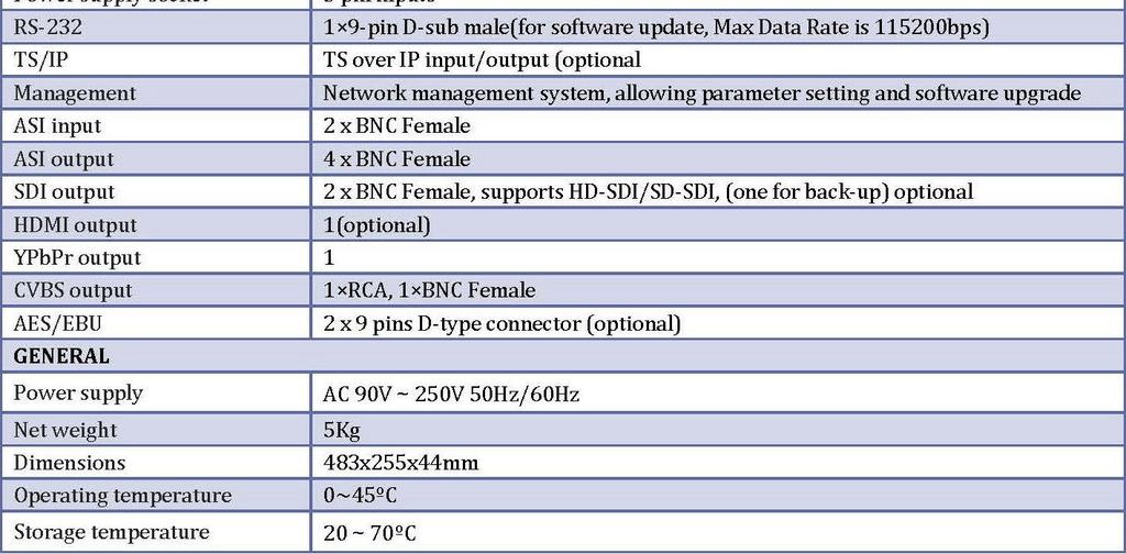
32 7. SPECIFICATION 32

33 33
34 8. ACCESORY LIST LAP 5000P-xx CD User Manual Power Cord RCA A/V Cable BNC Cable RS232-to-XRL cable 1pc 1pc 1pc 1pc 1pc 1pc 2pcs 9. IPTV CONFIGURATION QUICK GUIDE First of all, make sure that your unit is equipped with IP hardware board. If not, please contact your agent for information. 9.1 HOW TO RECEIVE A MULTICAST OR UNICAST STREAM Normally, the 5000P is set to IP Output by the factory. To set the 5000P to IP input mode, please follow the procedure below: 1. Only on the front panel is accessible, go to Main Menu System Optional function External board type IP in 2. Switch off the unit, and then switch it on again. Then the unit will become IP in, and the FACTORY DEFAULT setting will not change this IP direction. And at the same time, the menu structure on front panel & HDMS (the PC management software) will be changed accordingly. To receive a multicast/unicast stream: 1. Go to the Main menu Inputs Ethernet 34
35 2. Set the IP address & parameters for the IP hardware board, Stream IP addr enter the IP address for this IP hardware board (should be the same network section of the Stream Gateway, this depends on the characteristic of the gateway) Stream Netmask enter the network submask for this IP hardware board Stream Gateway enter the Gateway address for this IP hardware board Stream MAC addr Show the MAC address of this IP hardware board, read only. 3. Set the parameters for the incoming IP stream. On the same sub menu: Multicast IP addr enter the multicast IP address for the incoming stream (for the addresses inside to are belonging to multicast, for others else are belonging to unicast, the 5000P will identify it automatically) Multicast UDP port enter the port number of the incoming stream Protocol enter the protocol of the incoming stream, 5000P supports UDP and RTP. Output Smoothing Clock recover method from IP incoming stream, MUST set to Auto (both Auto & Fixed rate are for experimental test only). TS Bit Rate set to the bit rate of incoming stream in experimental test, this value will be ignored by 5000P if Output Smoothing = Auto in previous step. 4. After previous steps, 5000P will capture the incoming IP stream immediately. Normally it takes seconds to lock the stream. You can go to the Main menu inputs Status IP IN to check the bit rate of incoming stream. 5. Finally, if user wants to watch TV decoded from IP incoming stream on the output of 5000P, don t forget to set the decoder portion of 5000P to select IP as the program source. 35
36 9.2 HOW TO SET THE UNICAST/MULTICAST OUTPUT If the IP hardware board is configured as IP Input, please follow below procedure to change it to IP output: 1. Only on the front panel is accessible, go to Main Menu System Optional function External board type IP Out 2. Switch off the unit, and then switch it on again. Then the unit will become IP Out, and the FACTORY DEFAULT setting will not change this IP direction. And at the same time, the menu structure on front panel & HDMS (the PC management software) will be changed accordingly. To set Unicast/Multicast output, please follow the procedure below: 1. Go to the Main menu Outputs Ethernet 2. Set the IP address & parameters for the IP hardware board: Stream IP addr enter the IP address for this IP hardware board (should be the same network section of the Stream Gateway, this depends on the characteristic of the gateway) Stream Netmask enter the network submask for this IP hardware board Stream Gateway enter the Gateway address for this IP hardware board Stream MAC addr Show the MAC address of this IP hardware board, read only. 3. Set the universal parameters for the output IP stream. On the same sub menu: Gate MAC Address here the MAC address must be set as the as the MAC address of the Gateway where 5000P is located. Protocol enter the protocol of the output stream, 5000P supports UDP and RTP. TS Pkts Per UDP set the quantity of TS packages that will be carried IP package. The range goes from 1 ~
37 Time to Live set the TTL for the output IP package. Type of Service set the type of service for the output IP stream Source set the wanted stream output via IP. Mode Set the IP output mode as IPTV mode or DVB mode. 4. If the mode is set to be DVB mode, please follow below procedure DVB mode. If the mode is set to be IPTV mode, please go to procedure IPTV mode directly. DVB mode: Uni/Multicast Setup set the address and port parameters for the IP stream. Press Enter to go to the submenu. As below: Multicast IP enter the multicast IP address for the output stream (for the addresses inside to are belonging to multicast, for others else are belonging to unicast). Multicast UDP Port enter the port number of the output stream. Target Mac Addr set the MAC Address of the receiving device. The parameter will be used only when the receiving device is located under the same gateway. The parameter will be ignored by 5000P if the receiving device is located under other remote network or under different gateway. IPTV mode: Uni/Multicast Setup Press Enter to go to the submenu. As below: Max Channels set the quantity of multicast/unicast channels. Channel 0 set the private parameters for Multicast / Unitcast channel 0. Press Enter to go to the submenu. 0-Uni/Multicast IP enter the multicast IP address for the output stream (for the addresses inside to are belonging to multicast, for others else are belonging to unicast). 37
38 0-Uni/Multicast Port enter the port number of the output stream. 0-Target MAC address set the MAC Address of the receiving device. The parameter will be used only when the receiving device is located under the same gateway. The parameter will be ignored by 5000P if the receiving device is located under other remote network or under different gateway. 0-Switch turn on/off channel 0. 0-Program select the programs that want to be outputted via channel 0. For other channels, please refer to IPTV mode settings. 38
39 Latin American Power CABA, Argentina. Tel.: +54 (11) Cel.:+54 9(11)
EN-264 DVB MPEG-4 HDTV ENCODER & TRANSCODER - 0 MI1720 -
 EN-264 DVB MPEG-4 HDTV ENCODER & TRANSCODER - 0 MI1720 - SAFETY NOTES Read the user s manual before using the equipment, mainly " SAFETY RULES " paragraph. The symbol on the equipment means "SEE INSTRUCTION
UC-450E+ MPEG-4 HD/SD Encoder. User Manual. Version:
 UC-450E+ MPEG-4 HD/SD Encoder User Manual Version: 07302012-01 CONTENTS UC-450E+ MPEG-4 HD Encoder... 0 Chapter 1 Product Outline... 1 1.1Outline... 1 1.3 Specifications... 2 1.4 Block Diagram... 3 Chapter
SRD x DVB- S/S2 SD/HD Decoder
 SRD 8000 4x DVB- S/S2 SD/HD Decoder TABLE OF CONTENTS 1. SAFETY INSTRUCTION... 4 2. Overview... 5 3. Technical Specification... 6 3.1. Input Port... 7 3.2. Output Port... 7 4. Equipment composition...
DVBCommunity - cообщество профессионалов ЦТВ 4IN1 DVB-S2 IP/SPTS IRD with 4CI >>User Manual
 4IN1 DVB-S2 IP/SPTS IRD with 4CI >>User Manual Contents 1 SAFETY INSTRUCTION... 1 2 Overview... 2 2.1 Function and Application... 2 2.2 Size (1U Rack)... 2 3 Main Feature... 3 4 Technical Specification...
DMP900 Digital Media Platform
 DMP900 Digital Media Platform DMP900 Digital Media Platform is the next generation of intelligent headend processing equipment that can be transformed into any type of digital headend or perform all kinds
Processor 8ASI / DVB-S2 (S) RF
 RF") Processor 8ASI / DVB-T RF User s Manual Processor 8ASI / DVB-S2 (S) RF CAS ID 4AEC User's Manual 1 Processor 8ASI / DVB-S2(S) RF User s Manual Overview Construction Front Panel Rear Panel Main features
Processor 8ASI / DVB-T RF User s Manual Processor 8ASI / DVB-S2 (S) RF CAS ID 4AEC User's Manual 1 Processor 8ASI / DVB-S2(S) RF User s Manual Overview Construction Front Panel Rear Panel Main features
DVB-S/S2 to IP UDP/MPTS Gateway User Manual
 DVB-S/S2 to IP UDP/MPTS Gateway User Manual Contents 1 SAFETY INSTRUCTION... 2 2 System Composition and Operating Principle... 2 2.1 System Composition... 2 3 Installation Guide... 3 3.1 Installation Preparation...
SD ENCODER AND MODULATOR YPbPr & CVBS TO DVB-T DIGITAL RF SD4250 USER MANUAL
 SD ENCODER AND MODULATOR YPbPr & CVBS TO DVB-T DIGITAL RF SD4250 USER MANUAL All-in-one encoder and modulator for dual SD source. Allows 4 sets of Audio/Video source to be extended throughout a traditional
User Manual DXP-3800EC
 User Manual Brighten Your Digital View! DXP-3800EC 8-Way MPEG-2 SD Encoder Contents 01 Notice 03 Before Using the Device 04 1 Overview 04 2 Features 05 3 Technical Specifications 06 4 Block Diagram 06
NetPlus M400. Integrated Receiver/Decoder FEATURES
 NetPlus M400 Integrated Receiver/Decoder The NetPlus M400 is a broadcast-grade, satellite integrated receiver/decoder (IRD) that supports a wide range of global standards for video and audio compres-sion.
DHE-1000 MPEG4 HD ENCODER. MPEG4 system with IP output. Technical documentation / Instruction set
 DHE-1000 MPEG4 HD ENCODER MPEG4 system with IP output Technical documentation / Instruction set Teletechnika Ltd. 3rd Edition / 6 th November 2012 General description The MPEG-2 compression that brought
RL-DM Input DVB-T Encoder / Modulator User Guide and Install Manual
 ZyCastR Radio Frequency Range digi-mod RL-DM4000+ www.digi-modbyzycast.com RL-DM4000+ 4 Input DVB-T Encoder / Modulator User Guide and Install Manual Table of Contents Safety Precautions 2 Package Contents
User Manual EN way H.264 HD/SD Encoder and Modulator Series. EN-8000 Series User Maunal. Brighten Your Digital View!
 User Manual Brighten Your Digital View! EN-8000 8-way H.264 HD/SD Encoder and Modulator Series EN-8000 Series Rev: A www.antiktech.com Contents 1. Features and Order Information... 2 2. ModelList... 2
HDM-500T. DVB-T HD Encoder & Modulator
 HDM-500T DVB-T HD Encoder & User Manual Thank you for buying this encoder modulator. Please read this manual carefully to install, use and maintain the encoder modulator in the best conditions of performance.
TBS8510 Transcoder Server User Guide
 TBS8510 Transcoder Server User Guide Copyright TBS Technologies 2005-2019 All Rights Reserved 2019-01-08 1 / 53 TBS8510 User Guide Catalog 1. Product Overview... 4 1.1 Product Presentation... 4 1.2 Product
Installation Manual. 65 Interactive LED/LCD. Model: HILF65101 (64.56 )
") Installation Manual 65 (64.56 ) Model: HILF65101 65 Interactive LED/LCD QUICK SETUP GUIDE For further information, see the user manual. Please contact directly if you have questions on the use of the touch
Installation Manual 65 (64.56 ) Model: HILF65101 65 Interactive LED/LCD QUICK SETUP GUIDE For further information, see the user manual. Please contact directly if you have questions on the use of the touch
MT /12-Slot Digital MultiTasker
 /12-Slot Digital MultiTasker Welcome! We greatly appreciate your purchase of the MT302-121 12-Slot Digital MultiTasker Enclosure. We are sure you will find it reliable and simple to use. Superior performance
User Guide and Installation Manual
 User Guide and Installation Manual HDME102 / HDME202 / HDME402 Single / Dual / Quad Input QAM Encoder / Modulator 1 HDME102/202/402 Manual V1.0 Table of Contents Safety Precautions...3 Package Contents...3
Operating instruction
 Professional Headend Solutions Operating instruction Contents 1. Introduction... 2 1.1 Safety and operating instructions... 2 1.2 Contact... 2 1.3 Basic properties... 3 1.4 Unit options... 3 1.5 Basic
INSTALLATION & CONFIGURATION MANUAL
 INSTALLATION & CONFIGURATION MANUAL FDM-8000i 8-port SD Digital Modulator with IP FDM-8000i Manual V1.0 TABLE OF CONTENTS SAFETY PRECAUTIONS... 3 PACKAGE CONTENTS... 4 PRODUCT DESCRIPTION... 4 SPECIFICATIONS...
HD-4002DM Quad Input DVB-T HD Encoder / Modulator User Guide and Install Manual
 ZyCastR Radio Frequency Range digi-mod HD-4002DM www.digi-modbyzycast.com HD-4002DM Quad Input DVB-T HD Encoder / Modulator User Guide and Install Manual Table of Contents Safety Precautions... 2 Package
User Manual. Terrestrial DVB-T/T2 to IPTV Converter CT2IP-8032
 User Manual Terrestrial DVB-T/T2 to IPTV Converter CT2IP-8032 ZyCast Technology Inc. No. 33, Lane 181, Chung Hwa Road Section 4, Hsin Chu, Taiwan 30060 Tel: +886-3-5400-949 Fax: +886-3-5400-413 E-mail:
NDS3524 DVB-T SD&HD Encoder & Modulator with USB. --- Home Use. User Manual
 NDS3524 DVB-T SD&HD Encoder & Modulator with USB --- Home Use User Manual Thank you for buying this encoder modulator. Please read this manual carefully to install, use and maintain the encoder modulator
Quick Start Guide. Installation Summary
 Quick Start Guide Installation Summary These instructions can help you connect and operate the FS2 quickly. For additional details, please see the FS2 Installation and Operation Guide on the supplied DVD..
User s Manual. HD Multi-format Video Encoder. Model Name: Z3-MVE-02
 Z 3 Technology User s Manual HD Multi-format Video Encoder Model Name: Z3-MVE-02 Version 1.04.16 July 17, 2012 Before attempting to connect or operate this product, please read these instructions carefully
User Guide and Install Manual
 digi-mod HD-4797 www.digi-modbyzycast.com HD-4797 4-Input HD Digital Modulator with HDMI Loop Through and IR User Guide and Install Manual TABLE OF CONTENTS SAFETY PRECAUTIONS...2 PACKAGE CONTENTS...2
This manual describes the installation, setup and operation of this equipment in details.
 About This Manual This manual describes the installation, setup and operation of this equipment in details. Please read it carefully to make sure you can operate the multiplexer correctly. Important Avoid
Twin tuner HD satellite receiver OS 2. Quick Start Guide
 Twin tuner HD satellite receiver OS 2 Quick Start Guide OS 2 - HD DVB-S / DVB-S2 Satellite Tuner - MPEG-4, H.264 & MPEG-2 Compliant - 405MHz Dual Core Broadcom MIPS Processor - 256 MB NAND Flash / 8MB
Digital Encoder & Transcoder. Quick Installation Guide
 Digital Encoder & Transcoder Quick Installation Guide 1. Installation Instruction 1.1 Mounting unit to a 19 rack When selecting the installation site, try to comply with the following: Protective Ground
Installation Manual. Mounting Instructions Mechanical Mounting. Luminato. Teleste Corporation
 Luminato Installation Manual Teleste Corporation Mounting Instructions Mechanical Mounting Luminato Mechanical Installation, agile_59300316, rev0044 Introduction 1 Contents Introduction 4 General... 4
Quick Start Guide. Installation Summary
 Quick Start Guide Installation Summary These instructions can help you connect and operate the FS2 quickly. For additional details, please see the FS2 Installation and Operation Guide on the supplied DVD..
TBS8520 Transcoder Server User Guide
 TBS8520 Transcoder Server User Guide Copyright TBS Technologies 2005-2018 All Rights Reserved 2018-06-21 1 / 37 TBS8520 User Guide Catalog 1. Product Overview... 3 1.1 Product Presentation... 3 1.2 Product
4Ch SDI to IP+ASI MEPG-2 H.264 Encoder. User Manual B-SDI-ASI-IP-4CH
 4Ch SDI to IP+ASI MEPG-2 H.264 Encoder User Manual B-SDI-ASI-IP-4CH Intended Audience About This Manual This user manual has been written to help people who have to use, to integrate and to install the
MA5400 IP Video Gateway. Introduction. Summary of Features
 MA5400 IP Video Gateway Introduction The MA5400 IP Video Gateway bridges the gap between the MPEG-2 and IP domains providing an innovative solution to the need to transport real-time broadcast quality
Installing and Managing the Switch
 CHAPTER 2 This chapter describes how to install and manage the Cisco SFS 7008 system hardware and contains these sections: Safety, page 2-2 Preparing the Site, page 2-3 Rack-Mounting the Switch, page 2-4
Operating instruction
 Professional Headend Solutions Operating instruction Contents 1. Introduction... 2 1.1 Safety and operating instructions...2 1.2 Contact...2 1.3 Basic properties...3 1.4 Unit options...3 1.5 Features...3
User Instructions Multi-Channel H.264 HD Multimedia System
 User Instructions Multi-Channel H.264 HD Multimedia System High Definition Video Processor Module DM8107 Rapid Prototyping System Model Name: Z3-MVPR-02 DOC-USR-0006-01 Manual Version 1.0.3 Software Version
DVQ INSTALLATION & CONFIGURATION MANUAL DVQAM-1 / DVQAM-2. Single and Dual Input QAM Encoders / Modulators
 INSTALLATION & CONFIGURATION MANUAL DVQAM-1 / DVQAM-2 Single and Dual Input QAM Encoders / Modulators TABLE OF CONTENTS SAFETY PRECAUTIONS... 3 PACKAGE CONTENTS... 4 PRODUCT DESCRIPTION... 4 SPECIFICATIONS...
MPEG-2 / H.264 Mini Encoder / Transcoder
 MPEG-2 / H.264 Mini Encoder / Transcoder User s Manual Version: 1.0 Date: May 2013 MPEG-2 /H.264 Mini Encoder/Transcoder User s Manual CONTENT DIRECTORY 1. PRODUCT OUTLINE 1.1. OUTLINE 1.2. THE ENCODER
Installation Manual. Model: HILU Ultra HD Interactive Flat Panel Display
 Installation Manual Model: HILU750 '' Ultra HD Interactive Flat Panel Display QUICK SETUP GUIDE For further information, see the User Manual. Please contact HITACHI directly if you have questions on the
Application. Contents of Package. Inspect the CyberSwitch upon receipt. The package should contain the following items:
 Overview CyberPower power manager CyberSwitch is the ultimate power control center to manage multiple network devices via the Internet. After installing the hardware and setting up an IP address, this
AVP 3000 Voyager Configuration Packs
 AVP 3000 Voyager Configuration Packs The AVP 3000 Voyager is the latest generation of the market leading Voyager product for live news, sports and entertainment, capable of multi-codec, multi-format and
99 Washington Street Melrose, MA Phone Toll Free Visit us at
 99 Washington Street Melrose, MA 02176 Phone 781-665-1400 Toll Free 1-800-517-8431 Visit us at www.testequipmentdepot.com Table of Contents 1. General Safety Requirements... 1 2. Safety Terms and Symbols...
The VeCOAX PRO2 HD IP is the #1 Best HD Quality & Best Price Video Encoder on the market, perfect
 The VeCOAX PRO2 HD IP is the #1 Best HD Quality & Best Price Video Encoder on the market, perfect solution to distribute HD video signals over wifi, lan, wan, internet, to an unlimited number of network
TIME SERVER NETSILON. Quick start.
 TIME SERVER NETSILON Quick start This document refers to the following products: 907,900 NETSILON 7 (100-240 VAC) 907,901 NETSILON 7 (18-36 VDC) 907,902 NETSILON 7 (100-240 VAC + 18-36 VDC) www.bodet-time.com
ATS-16 HV USER MANUAL. Automatic Transfer Switch 16A / 230Vac V090318
 ATS-16 HV Automatic Transfer Switch 16A / 230Vac USER MANUAL V090318 SAFETY Intended use The ATS-16 HV device serves as a power source selector to provide improved power supply for connected loads. ATS-16
Cisco D9034-S Encoder
 Cisco D9034-S Encoder Product Overview To help optimize bandwidth utilization in digital transmission systems, the Model D9034-S Encoder is designed to deliver high-quality MPEG-4 part 10 (also known as
INSTALLATION & CONFIGURATION MANUAL. resi-linx RL-IP1000 HD IP Streaming Server
 INSTALLATION & CONFIGURATION MANUAL resi-linx RL-IP1000 HD IP Streaming Server TABLE OF CONTENTS SAFETY PRECAUTIONS...2 PACKAGE CONTENTS...2 PRODUCT DESCRIPTION...3 SPECIFICATIONS...4 INSTALLATION, UNPACKING
DIRECTORY. Chapter 1 Product Introduction Outline Main Features Specifications Principle Chart...
 DIRECTORY Chapter 1 Product Introduction... 1 1.1 Outline... 1 1.2 Main Features... 1 1.3 Specifications... 2 1.4 Principle Chart... 2 1.5 Appearance and Illustration... 3 Chapter 2 Installation Guide...
User Guide and Install Manual
 digi-mod HD-1605 www.digi-modbyzycast.com HD-1605 Single Input DVB-T HD Digital Modulator with Delayed Audio Output User Guide and Install Manual TABLE OF CONTENTS SAFETY PRECAUTIONS...2 PACKAGE CONTENTS...2
NetUP HDMI Encoder 8x
 NetUP HDMI Encoder 8x User s manual NMS Version: 2.2.5 SW: 0.17F HW: 0.8 August 10, 2015 CONTENTS Chapter 1 Product Introduction... 1 1.1 Outline... 1 1.2 Main Features... 1 1.3 Specifications... 2 1.4
User Manual Trophy TA-1001HD
 Trophy TA-1001HD DVB-C HDTV digital receiver Trophy-Access decoder Personal Video Recorder Contents Trophy TA-1001HD Device Operation 3 Specification 4 Front panel 5 Back panel 5 Remote control 6 Connection
DVB-S2/T2/C HD Combo STB Model:Timbox-Combo
 DVB-S2/T2/C HD Combo STB Model: Main Feature: DVB-T/T2, DVB-S/S2 and DVB-C tuners and demodulations MPEG-2/MPEG-4AVC/H.264 SD/HD decoding Automatic, manual and full band channel scanning Manage up to 1000
HD IR Waterproof Fixed Network Camera. Quick Start Guide. Version 1.0.0
 HD IR Waterproof Fixed Network Camera Quick Start Guide Version 1.0.0 Welcome Thank you for purchasing our network camera! This quick start guide is designed to be a reference tool for your system. Please
MODEL 805 USER MANUAL
 MODEL 805 USER MANUAL All Rights Reserved Page 1 of 12 UNPACKING & INSPECTION Save all packing materials they are required for returns and warranty service. Inspect the 805 and packing materials for any
Cisco DCM Series D9901 Digital Content Manager IP Video Gateway
 Cisco DCM Series D9901 Digital Content Manager IP Video Gateway Today s video contribution networks are evolving rapidly with the dual drivers of increased demand, for high-definition TV, and a need for
AVG-UHD4K-44. Features
 Features The AVG-UHD4K-44 4x4 HDMI Matrix Switcher is a professional 4x4 HDMI Matrix Switcher that is capable of receiving up to 4 HDMI 2.0 & HDCP 2.2 compliant signals and outputting 4 HDMI 1.4 & HDCP
Table of Contents. 3.1 Front/Rear Panel and User Interface Front Panel Rear Panel User Interface...
 General Warranty OWON warrants that the product will be free from defects in materials and workmanship for a period of 2 years (1 year for accessories) from the date of purchase of the product by the original
DHP 400A. Module Specifications: Product Outline. Key Fetures. DHP 400A Head-end Processor
 DHP 400A Product Outline Redundancy Power Supply (Optional) Two options for redundancy power supply: Non-Hot Plugging (option 1) Support Hot Plugging (option 2) DHP400A DTV head-end processor is the new
Installing the Cisco Unified Videoconferencing 3545 MCU
 CHAPTER 2 Installing the Cisco Unified Videoconferencing 3545 MCU The Cisco Unified Videoconferencing 3545 MCU works together with a Cisco Unified Videoconferencing 3545 EMP Enhanced Media Processor (EMP)
IP/ASI Adapter GM-2730C User Manual
 IP/ASI Adapter GM-2730C User Manual GOSPELL Digital Technology Co., Ltd GOSPELL Digital Technology Co., Ltd Safety Instructions Read this manual carefully before start operating the device. Removal of
KR425H-16. Encoder Modulator User Manual
 KR425H-16 Encoder Modulator User Manual Intended Audience About This Manual This user manual has been written to help people who have to use, to integrate and to install the product. Some chapters require
PA Series. Available in 6.0MP and 8.0MP
 Camera Quick Install Guide PA Series Available in 6.0MP and 8.0MP Thank you for purchasing a PA Series CCTV Surveillance Camera. This Quick Install Guide covers basic setup, installation and use of your
SMP181-HLS. User Guide V1.1-N
 SMP181-HLS User Guide V1.1-N Revision History Date Version Description Author 12/8/2016 1.0 First Draft MS 3/5/2017 1.1-N UI Update HL This guide contains some symbols to call your attention. DANGER CAUTION
Model 2460-KIT. Screw Terminal Connector Kit. Description / September 2014 *P * 1
 Keithley Instruments 28775 Aurora Road Cleveland, Ohio 44139 1-800-935-5595 http://www.keithley.com Model 2460-KIT Screw Terminal Connector Kit Description The Model 2460-KIT Screw Terminal Connector Kit
3700 SERIES USER MANUAL
 SAFETY GUIDE This manual contains the precautions necessary to ensure your personal safety as well as for protection for the products and the connected equipment. These precautions are highlighted with
Amb-OS Media, LLC AMR-100I
 Amb-OS Media, LLC AMR-100I Operations Manual Firmware 2.28 Revision 2 10/09/14 SUPPORT INFORMATION Email: support@amb-os.com Phone 877AMBOS2U (877) 262-6728 AMB-OS WEB PAGE for program downloads, RSS feed
HD ENCODER AND MODULATOR HDMI TO DVB-T DIGITAL RF (MPEG-4) 14MM-DM05 USER MANUAL 3-14
 14MM-DM05 USER MANUAL 3-14") HD ENCODER AND MODULATOR HDMI TO DVB-T DIGITAL RF (MPEG-4) 14MM-DM05 USER MANUAL 3-14 PRODUCT INTRODUCTION Indicator LCD Window Control Buttons RF out RF mix in USB Port for Upgrade HDMI in DC 12V Grounding
HD ENCODER AND MODULATOR HDMI TO DVB-T DIGITAL RF (MPEG-4) 14MM-DM05 USER MANUAL 3-14 PRODUCT INTRODUCTION Indicator LCD Window Control Buttons RF out RF mix in USB Port for Upgrade HDMI in DC 12V Grounding
Models 2601B, 2602B, and 2604B System SourceMeter Instruments Quick Start Guide
 Models 2601B, 2602B, and 2604B System SourceMeter Instruments Quick Start Guide Safety precautions Observe the following safety precautions before using this product and any associated instrumentation.
Manual Version: V1.00. Video Decoder User Manual
 Manual Version: V1.00 Video Decoder User Manual Thank you for purchasing our product. If there are any questions, or requests, please do not hesitate to contact the dealer. Copyright Copyright 2016 Zhejiang
INSTALLATION & CONFIGURATION MANUAL. HD-1000DM / HD-2000DM / HD-4000 (DVB-T HD Series) Single / Dual / Quad Input Encoders / Modulators
 Single / Dual / Quad Input Encoders / Modulators") INSTALLATION & CONFIGURATION MANUAL HD-1000DM / HD-2000DM / HD-4000 (DVB-T HD Series) Single / Dual / Quad Input Encoders / Modulators TABLE OF CONTENTS SAFETY PRECAUTIONS... 3 PACKAGE CONTENTS... 4 PRODUCT
INSTALLATION & CONFIGURATION MANUAL HD-1000DM / HD-2000DM / HD-4000 (DVB-T HD Series) Single / Dual / Quad Input Encoders / Modulators TABLE OF CONTENTS SAFETY PRECAUTIONS... 3 PACKAGE CONTENTS... 4 PRODUCT
Videon Product Manual. Shavano Encoder
 Videon Product Manual Shavano Encoder Copyright 2018 Videon Central, Inc. All rights reserved. No part of this publication may be reproduced, distributed, or transmitted in any form or by any means, including
Cisco D9054 HDTV Advanced Compression Encoder
 Cisco D9054 HDTV Advanced Compression Encoder Product Overview The MPEG-4 part 10 (H.264/AVC) D9054 Encoder is the right choice for any operator who wants to compress high-definition video using MPEG-4
Model No. ZE v2 1
 User Manual / Installation Guide AV Over Ethernet Gigabit Adaptor Model No. ZE5000 Warning! It will cause malfunction if the AV Adaptor is operating with unspecified power supply adaptor or incorrect power
MADI-PC MADI RECORDING SYSTEM
 MADI-PC MADI RECORDING SYSTEM USER MANUAL V1.0 1 P a g e Table of Contents INTRODUCTION... 3 IMPORTANT SAFETLY PRECAUTIONS... 4 General Safety... 4 Caution... 4 Power Safety... 5 Installation Notes...
USER GUIDE 1 of 26 STAGEGRID 4000 User Guide rev.01 abr-18
 USER GUIDE 1 of 26 STAGEGRID 4000 User Guide rev.01 abr-18 SUMÁRIO About... 2 STAGEGRID 4000... 2 SoundGrid... 3 System Requirements... 3 Hardware... 4 Package Contents... 4 Rack Installation... 5 Setups...
Videon Product Manual
 Videon Product Manual Greylock and Sorona Encoders/Decoders Document Number 10004134-R06 Copyright 2018 Videon Central, Inc. All rights reserved. No part of this publication may be reproduced, distributed,
Warning! PRECAUTIONS
 User Manual / Installation Guide AV Over Ethernet Gigabit Adaptor Model No. ZE5000/ ZE5000 + Warning! It will cause malfunction if the AV Adaptor is operating with unspecified power supply adaptor or incorrect
R4, R8, R16 Digital Video Recorders Quick Setup Guide
 R4, R8, R16 Digital Video Recorders Quick Setup Guide This guide provides instructions to initially setup the R16 (16 channel) digital video recorders (DVR). The DVR supports these advanced features: 2
SM-4X4-4K18GB-LC. Low Cost 4K HDMI Video Matrix Switch: 4x4. Operating Instruction
 SM-4X4-4K18GB-LC Low Cost 4K HDMI Video Matrix Switch: 4x4 Operating Instruction 1 Thank you for purchasing this product. For optimum performance and safety, please read these instructions carefully before
ANI SWH. PDU: Per Outlet Control and Total Current Monitoring INSTRUCTION MANUAL
 ANI-15115-08SWH PDU: Per Outlet Control and Total Current Monitoring INSTRUCTION MANUAL 122 Rose Ln., Suite 303, Frisco, Texas 75034 TOLL FREE: 1-877-ANEUTRON TOLL: (469) 362-9228 Email: sales@a-neutronics.com
MultiTasker. MultiTasker Design Guide
 MultiTasker Design Guide MultiTasker ETHERNET 00-40V -6A Doc. #: 66-00-00 www.altinex.com Copyright 06 MultiTasker manufacturing process Product projections Customer places an order Enclosures and Cards
Taurus Super-S3 LCM. Dual-Bay RAID Storage Enclosure for two 3.5-inch Serial ATA Hard Drives. User Manual March 31, 2014 v1.2
 Dual-Bay RAID Storage Enclosure for two 3.5-inch Serial ATA Hard Drives User Manual March 31, 2014 v1.2 www.inxtron.com EN Table of Contents Table of Contents 1 Introduction... 1 1.1 Technical Specifications...
Getting Started with the Agilent Serial BERT N4906B. You only need a few minutes to get started with the Serial BERT.
 Getting Started with the Agilent Serial BERT N4906B You only need a few minutes to get started with the Serial BERT. This Getting Started Brochure helps you to quickly understand the operating principles
Chengdu Dexin Digital Technology Co., Ltd.
 NDS3218A 8 in 1 MPEG4 AVC/H.264 HD Encoder User s Manual Date: 2013-02-07 Version: 1.0 NMS Version: 2.2.5 SW: 0.17F HW: 0.8 Chengdu Dexin Digital Technology Co., Ltd. DIRECTORY Chapter 1 Product Introduction...
Getting Started. About the Front Panel LCD
 This section describes how to use the D9800 Network Transport Receiver front panel and web GUI, as well as how to initially set up the D9800 receiver. There are two ways to configure the D9800 unit: front
PacketBand TDM-4 Quickstart Guide V3.2
 2012 Patapsco Designs Ltd Patapsco has recently been acquired by Communications Systems, Inc. (CSI) and is now a part of Transition Networks, Inc., a subsidiary of CSI. The high-quality, reliable Transition
Cisco D9036 Modular Encoding Platform
 Cisco D9036 Modular Encoding Platform Product Overview The Cisco D9036 Modular Encoding Platform provides multi-resolution, multi-format encoding for applications requiring high levels of video quality.
Table of Contents Quick Install Guide page Introduction Safety Rack System Precautions ESD Precautions...
 Table of Contents Quick Install Guide page 1 EN English Table of Contents 1. Introduction... 2 1.1 Safety... 2 1.2 Rack System Precautions... 2-3 1.3 ESD Precautions... 3... 3 1... 3 2 Fitting PSU s...
USER GUIDE AND MANUAL. Dual Input HD Digital Encoder-Modulator with ASI. MODEL: DT-IPTV-QAM-ASI-2H Version 1.0 Last Update:
 USER GUIDE AND MANUAL Dual Input HD Digital Encoder-Modulator with ASI MODEL: DT-IPTV-QAM-ASI-2H Version 1.0 Last Update: 01-15-2019 DT-IPTV-QAM-ASI-2H Manual V1.0 01152019 NACE Brands is the leading brand
Model 2380 Rack-Mount Kit
 Keithley Instruments 28775 Aurora Road Cleveland, Ohio 44139 1-800-935-5595 http://www.tek.com/keithley Model 2380 Rack-Mount Kit Installation Instructions Introduction The Model 2380 Fixed Rack-Mount
CHASSIS-1. Form number 7660
 VideoBridge Chassis Unit CHASSIS-1 Quick Installation Guide Form number 7660 Table of Contents 1 2 3 4 5 About this Quick Installation Guide...3 Quick Quick Installation Guide...3 Safety...3 Verifying
User manual. 64-Channel Real-Time TS Analyzer. web-based user interface. for the built-in. 64-Channel Real-Time TS Analyzer Web Interface CW-4957
 64-Channel Real-Time TS Analyzer User manual for the built-in web-based user interface CableWorld Ltd. 1116 Budapest, Kondorfa u. 6/B, Hungary Tel.: +36 1 371 2590, Fax: +36 1 204 7839 E-mail: cableworld@cableworld.hu
Dear Customer FEATURES NOTICE. Operating Instructions
 HDMI Extender over Ethernet Dear Customer Thank you for purchasing this product. For optimum performance and safety, please read these instructions carefully before connecting, operating or adjusting this
INSTALLATION & CONFIGURATION MANUAL. CSD-1000B, CSD-2000B, CSD-4000B Single, Dual, Quad Input QAM Modulators
 INSTALLATION & CONFIGURATION MANUAL CSD-1000B, CSD-2000B, CSD-4000B Single, Dual, Quad Input QAM Modulators ZyCast Technology Inc. No. 33, Lane 181 Chung Hwa Road Section 4, Hsin Chu, Taiwan 30060 Tel:
Cisco DCM Series D9901 Digital Content Manager MPEG Processor
 Cisco DCM Series D9901 Digital Content Manager MPEG Processor Today s digital systems demand powerful, flexible and compact solutions that will allow the service provider to support new network architectures.
User Manual. Printer P-52RUE
 User Manual P-52RUE Overview 3 4 2 5 1 6 13 12 7 11 10 9 8 Overview Table 1 Paper feed button 8 Ethernet RJ45 connection 2 Status indicator 9 USB device connection 3 Paper cutter 10 RS232 connection 4
ANT- 4000E H P60 HD VIDEO ENCODER
 ANT- 4000E H.264 1080P60 HD VIDEO ENCODER User Manual Ver. 2.0 1 Safety Precautions We appreciate you purchasing the ANT-4000E. Before installing the product, please read the following carefully. Make
Model 2380 Rack-Mount Kit
 Keithley Instruments 28775 Aurora Road Cleveland, Ohio 44139 1-800-935-5595 http://www.tek.com/keithley Model 2380 Rack-Mount Kit Installation Instructions Introduction The Model 2380 Fixed Rack-Mount
Antenna Distributor ORDERCODE D1444
 Antenna Distributor ORDERCODE D1444 Congratulations! You have bought a great, innovative product from DAP Audio. The DAP Audio TAS series bring excitement to any venue. Whether you want simple plug-&-play