Chapter 10 Sections 1,2,9,10 Dr. Iyad Jafar
|
|
|
- Silvia Kennedy
- 5 years ago
- Views:
Transcription
1 Starting with Serial Chapter 10 Sections 1,2,9,10 Dr. Iyad Jafar
2 Outline Introduction Synchronous Serial Communication Asynchronous Serial Communication Physical Limitations Overview of PIC 16 Series The 16F87xA USART Summary 2
3 Introduction 3 Microcontrollers need to move data to and from external devices In general, two approaches Parallel Data word bits are transferred at the same time A wire is dedicated for each bit Simple and fast but expensive Short distances Serial Bits are transferred one after another over the same link/wire Requires complex hardware to transmit and receive Slow Short and long distances


4 Introduction Two memories of the same size. However, one uses parallel transfer while the other uses serial 4
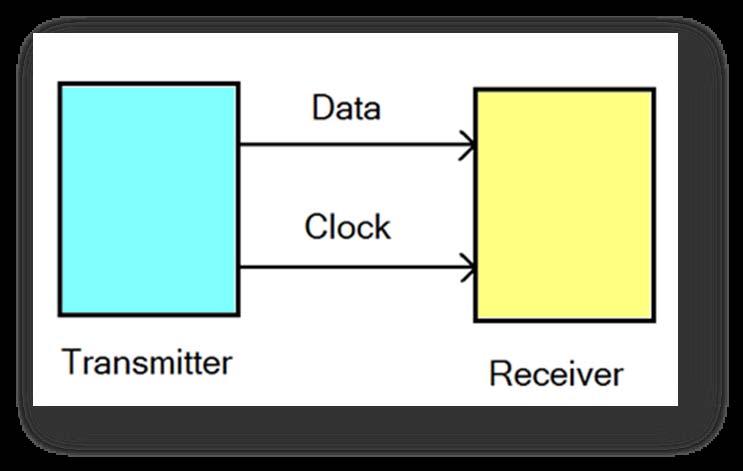
5 Serial Communication 5 Bits are transferred one after another on the same wire!!! Challenges How to distinguish the start and end of the bit? How to determine the start and end of a word? Two approaches Synchronous serial communication A separate clock signal is sent in parallel with the data Each clock cycle represents one bit duration Asynchronous serial communication No clock signal! Timing is derived from the data itself
6 Serial Communication Synchronous Asynchronous 6


7 Data inside the memory and microprocessor is formatted in parallel. How to transmit it serially? Shift registers Serial Communication 7

8 Synchronous Serial Communication General Serial Link 8 Synchronous link implemented using a microcontroller
9 Synchronous Serial Communication Advantages Simple hardware Efficient High speed 9 Disadvantages Extra line for the clock The bandwidth needed for the clock is twice the data bandwidth Data and clock may lose synchronization over long distance
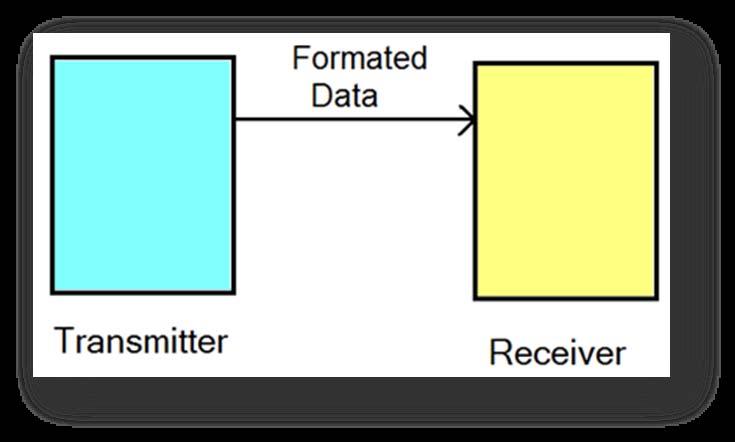
10 Asynchronous Serial Communication No clock signal! The transmitter and receiver should operate a clock at the same rate To synchronize the clocks of the transmitter and receiver, data is framed with a start and stop bits 10

11 Asynchronous Serial Communication Framing 11

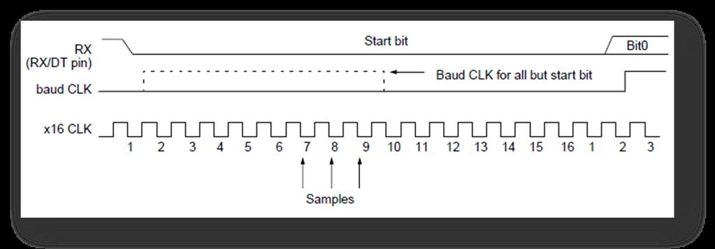
12 12 Asynchronous Serial Communication Synchronization
13 Physical Limitations Time Constant effect 13

14 Physical Limitations Transmission Line Effects Characteristic impedance and reflections Lines should be terminated properly 14
15 Physical Limitations Electromagnetic Interference 15
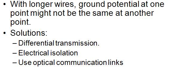
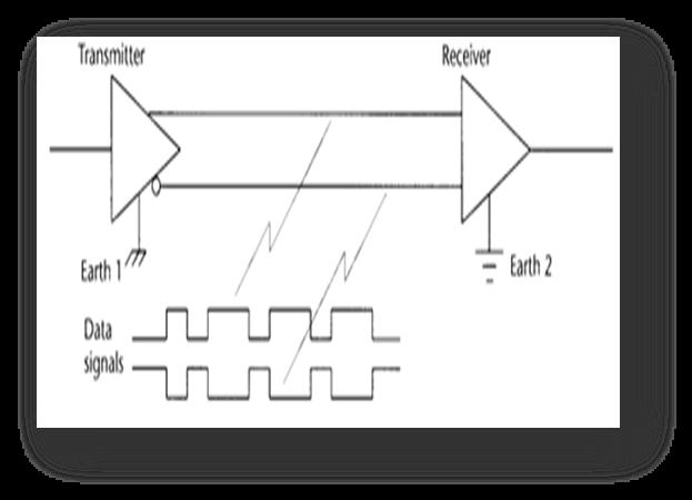

16 Physical Limitations Ground Differentials 16

17 Overview of the PIC 16 Series 17 We have already seen the PIC 16F84A Other members in the series have more features: Additional I/O ports More HW timers A/D converters LCD Drivers USARTs Synchronous Serial Comparators.


18 Overview of the PIC 16 Series 18
19 19 Overview of the PIC 16 Series Interrupt Logic for 16F874A/16F877A
20 Overview of the PIC 16 Series Device Pins Features 16F873A 16F876A 16F874A 16F877A 28 3 parallel ports, 3 counter/timers, 2 capture/compare/pwm, 2 serial, 5 10 bit ADC, 2 comparators 40 5 parallel ports, 3 counter/timers, 2 capture/compare/pwm, 2 serial, 8 10 bit ADC, 2 comparators 20
21 The 16F87xA USART 21 The 16F87XA family has a Universal Synchronous Asynchronous Receiver Transmitter (USART) Configurable Half duplex synchronous master or slave Full duplex asynchronous transmitter and receiver The USART shares pins with PORTC pin 7 being the receive line pin 6 being the transmit line Operation involves the following registers TXSTA (0x98) TXREG (0x19) RCSTA (0x18) RCREG (0x1A) SPBRG (0x99) PIE1 (0x8C) PIR1 (0x0C) INTCON (0x0B, 0x8B,0x10B,0x18B) TRISC (0x87)

22 The 16F87xA USART Asynchronous USART Transmitter Block Diagram 22
23 The 16F87xA USART Asynchronous USART Transmitter Operation Notes Data is transmitted LSB first on RC6 pin The shift register TSR is buffered by the TXREG (19H) and is not accessible as a memory location Transmission is controlled by the TXEN bit which enables the clock to start the transmission To enable serial transmission on RC6, bit SPEN in RCSTA register has to be set To transmit data, it must be loaded in the TXREG. It is transferred to TSR immediately if no transmission or after the stop bit from previous transmission is sent out Transmission status is provided by two bits: 23 TXIF flag in PRR1 register indicates the status of TXREG. It is set when data is transferred to TSR. It is cleared on writing to TXREG. (TXIF is cleared by hardware and it is read only). TRMT flag in TXSTA it is set when the shift register is empty Parity bit can be sent out by using TXD9 bit and TX9 in TXSTA
24 24 The 16F87xA USART TXSTA (98H)
25 The 16F87xA USART Steps for Using the asynchronous transmitter 1. Clear TRISC<6> bit to configure RC6 as output 2. Set the SPBRG (0x99) register and BRGH (TXSTA<2>) bit to choose the appropriate baud rate 3. Enable asynchronous serial port by clearing the SYNC (TXSTA<4>) bit and setting the SPEN bit (RCTSA<7>) 4. If interrupts are desired, set the TXIE (PIE1<4>), GIE (INTCON<7>), and PEIE (INTCON<6>) bits 5. If 9 bit transmission is desired, set the TX9 (TXSTA<6>) bit 6. Enable transmission by setting the TXEN (TXSTA<5>), which will set the TXIF (PIR1<4>) bit 7. If 9 bit transmission is selected, then the ninth bit should be loaded in TX9D (TXSTA<0>) 8. Load data in TXREG (0x19) to start the transmission 25


26 The 16F87xA USART Timing of asynchronous transmission Registers involved in asynchronous transmission 26

27 27 The 16F87xA USART Asynchronous Receiver
28 The 16F87xA USART Asynchronous USART Receiver Operation Notes 28 Data is received LSB first on RC7 pin Reception is enabled by the CREN bit At the heart of the block is the RSR register. Once a stop bit is detected, data is transferred to RCREG register, if it is empty, and the RCIF flag is set. (RCIF is cleared by hardware and it is read only). On receive interrupt can be enabled by RCIE bit The RCREG is FIFO double buffered register can be used to receive bytes while reception continues in RSR It can be read twice to read the received two bytes If a stop bit is detected in RSR and the RCREG is still full, an overrun error occurs and is indicated in OERR bit (The word is RSR is lost) If OERR bit is set, shifting stops in RSR and transfers to the RCREG is inhibited! To clear the framing error, clear the CREN bit. If the stop bit is received as clear in RSR a framing error occurs and is indicated by the FERR bit. The 9 th bit of data RCD9 and FERR are also double buffered. It is essential to read the RCSTA register before the RCREG to avoid losing the corresponding values of RCD9 and FERR
29 29 The 16F87xA USART RCSTA (18H)
30 The 16F87xA USART Steps for Using the asynchronous receiver 1. Set the SPBRG (0x99) register and BRGH (TXSTA<2>) bit to choose the appropriate baud rate 2. Enable asynchronous serial port by clearing the SYNC (TXSTA<4>) bit and setting the SPEN bit (RCTSA<7>) 3. If interrupts are desired, set the RCIE (PIE1<5>), GIE (INTCON<7>), and PEIE (INTCON<6>) bits 4. If 9 bit reception is desired, set the RX9 (RCSTA<6>) bit 5. Enable the reception by setting bit CREN (RCSTA<4>) 6. The RCIF (PIR1<5>) will be set when reception of one word is complete and an interrupt will be generated if RCIE is set 7. Read the RCSTA (0x18) to get the 9 th bit and determine if any error occurred (OERR, FERR) 8. Read the 8 bit received data by reading RCREG (0x1A) 9. If any error occurred, clear the error by clearing the CREN 30


31 The 16F87xA USART Timing of asynchronous reception Registers involved in asynchronous reception 31
32 The 16F87xA USART The BAUD Rate Generator The BAUD rate for USART is controlled by the value in the SPREG (99H), the SYNC and the BRGH bits in the TXSTA (19H) SYNC BRGH = 0 BRGH = 1 0 (asynchronous) F osc 64( SPBRG + 1) 16( 1) F osc SPBRG + 1 (synchronous) F osc 4( SPBRG + 1) 32
33 Example A program to transmit 3 bytes stored in locations 0x40, 0x41, and 0x42 serially with no parity at a rate of 9.6 Kbps. Assume PIC 16F877A with oscillator frequency of 20 MHz Requirements 1. setup the serial port for transmission 2. choose the appropriate value of SPBRG and BRGH to produce the required rate 33
34 Example Example 34 #include p16f877a.inc ; include the definition file for 16F77A org 0x0000 ; reset vector goto START org 0x0004 ; define the ISR ISR goto ISR org 0x0006 ; Program starts here START bsf STATUS, RP0 bcf STATUS, RP1 ; select bank 1 bcf TRISC, 6 ; set RC6 as output movlw D 31 movwf SPBRG ; set the SPBRG value bsf TXSTA, TXEN bcf STATUS, RP0 ; select bank0 bsf RCSTA, SPEN ; enable serial transmission movlw 0x40 mowf FSR ; FSR has the address of the first element
35 Example TX movf INDF, W ; read byte to transmit movwf TXREG ; store in the transmission register incf FSR, F ; increment FSR to point to next address WAIT btfss PIR1, TXIF ; check if the TXREG is empty goto WAIT movf FSR,W sublw 0x43 btfss STATUS, Z ; check if all values were transmitted goto TX DONE goto DONE end 35
36 Summary Serial communication transmits bits one after another in two modes: synchronous and asynchronous Stable and accurate clocking plays an important role in serial communication It is cheaper to use serial communication over long distances Some members of the 16 series are equipped with synchronous and asynchronous communication ports These ports can be configured to operated in different modes and rates 36
Section 21. Addressable USART
 21 Section 21. Addressable USART Addressable USART HIGHLIGHTS This section of the manual contains the following major topics: 21.1 Introduction... 21-2 21.2 Control Registers... 21-3 21.3 USART Baud Rate
Embedded Systems Programming and Architectures
 Embedded Systems Programming and Architectures Lecture No 10 : Data acquisition and data transfer Dr John Kalomiros Assis. Professor Department of Post Graduate studies in Communications and Informatics
Hi Hsiao-Lung Chan Dept Electrical Engineering Chang Gung University, Taiwan
 PIC18 Serial Port Hi Hsiao-Lung Chan Dept Electrical Engineering Chang Gung University, Taiwan chanhl@mail.cgu.edu.twcgu Serial vs. parallel data transfer 2 Simplex, half-, and full-duplex transfers 3
Serial Communication with PIC16F877A
 Serial Communication with PIC16F877A In this tutorial we are going to discuss the serial/uart communication using PIC16F877A. PIC16F877A comes with inbuilt USART which can be used for Synchronous/Asynchronous
Experiment 7:The USART
 University of Jordan Faculty of Engineering and Technology Department of Computer Engineering Embedded Systems Laboratory 0907334 7 Experiment 7:The USART Objectives Introduce the USART module of the PIC
ELCT 912: Advanced Embedded Systems
 ELCT 912: Advanced Embedded Systems Lecture 10: Applications for Programming PIC18 in C Dr. Mohamed Abd El Ghany, Department of Electronics and Electrical Engineering Programming the PIC18 to transfer
Serial Communication
 Serial Communication What is serial communication? Basic Serial port operation. Classification of serial communication. (UART,SPI,I2C) Serial port module in PIC16F887 IR Remote Controller Prepared By-
EET203 MICROCONTROLLER SYSTEMS DESIGN Serial Port Interfacing
 EET203 MICROCONTROLLER SYSTEMS DESIGN Serial Port Interfacing Objectives Explain serial communication protocol Describe data transfer rate and bps rate Describe the main registers used by serial communication
Example of Asyncronous Serial Comms on a PIC16F877
 /***************************************************************************************/ /* Example of Asyncronous Serial Comms on a PIC16F877 */ /* Target: PIC16F877 */ /* Baud: 9600 */ /* Bits: 8 */
ELE492 Embedded System Design
 Overview ELE9 Embedded System Design Examples of Human I/O Interfaces Types of System Interfaces Use of standards RS Serial Communication Overview of SPI, I C, L, and CAN Class //0 Eugene Chabot Examples
ELCT706 MicroLab Session #4 UART Usage for Bluetooth connection PC - PIC
 ELCT706 MicroLab Session #4 UART Usage for Bluetooth connection PC - PIC USART in PIC16F877A Universal Synchronous/Asynchronous Receiver Transmitter - Can receive and transmit - Can be synchronous or Asynchronous
Parallel IO. Serial IO. Parallel vs. Serial IO. simplex vs half-duplex vs full-duplex. Wires: Full Duplex. Wires: Simplex, Half-duplex.
 Parallel IO Parallel IO data sent over a group of parallel wires. Typically, a clock is used for synchronization. D[15:0] clk Serial IO Serial IO data sent one bit at a time, over a single wire. A clock
ELCT706 MicroLab Session #4 UART Usage for Bluetooth connection PC - PIC
 ELCT706 MicroLab Session #4 UART Usage for Bluetooth connection PC - PIC USART in PIC16F877A Universal Synchronous/Asynchronous Receiver Transmitter - Can receive and transmit - Can be synchronous or Asynchronous
APPLICATION NOTE 2361 Interfacing an SPI-Interface RTC with a PIC Microcontroller
 Maxim/Dallas > App Notes > REAL-TIME CLOCKS Keywords: DS1305, SPI, PIC, real time clock, RTC, spi interface, pic microcontroller Aug 20, 2003 APPLICATION NOTE 2361 Interfacing an SPI-Interface RTC with
FULL DUPLEX BIDIRECTIONAL UART COMMUNICATION BETWEEN PIC MICROCONTROLLERS
 FULL DUPLEX BIDIRECTIONAL UART COMMUNICATION BETWEEN PIC MICROCONTROLLERS Dhineshkaarthi K., Sundar S., Vidhyapathi C. M. and Karthikeyan B. M. Tech, School of Electronics Engineering, VIT University,
DHANALAKSHMI COLLEGE OF ENGINEERING, CHENNAI DEPARTMENT OF ELECTRICAL AND ELECTRONICS ENGINEERING. EE Microcontroller Based System Design
 DHANALAKSHMI COLLEGE OF ENGINEERING, CHENNAI DEPARTMENT OF ELECTRICAL AND ELECTRONICS ENGINEERING EE6008 - Microcontroller Based System Design UNIT III PERIPHERALS AND INTERFACING PART A 1. What is an
Asynchronous Transmission. Asynchronous Serial Communications & UARTS
 Asynchronous Transmission Asynchronous Serial Communications & UARTS 55:036 Embedded Systems and Systems Software asynchronous: transmitter and receiver do not share a common clock or explicitly coordinate
Design, Development & Implementation of a Temperature Sensor using Zigbee Concepts
 Design, Development & Implementation of a Temperature Sensor using Zigbee Concepts T.C.Manjunath, Ph.D. ( IIT Bombay ) & Fellow IETE, Ashok Kusagur, Shruthi Sanjay, Saritha Sindushree, C. Ardil Abstract
PIC16C7X 11.0 SYNCHRONOUS SERIAL PORT (SSP) MODULE SSP Module Overview. Applicable Devices
 MODULE SSP Module Overview. Applicable Devices") Applicable Devices PIC16C7X 11.0 SYNCHRONOUS SERIAL PORT (SSP) MODULE 11.1 SSP Module Overview The Synchronous Serial Port (SSP) module is a serial interface useful for communicating with other peripheral
Applicable Devices PIC16C7X 11.0 SYNCHRONOUS SERIAL PORT (SSP) MODULE 11.1 SSP Module Overview The Synchronous Serial Port (SSP) module is a serial interface useful for communicating with other peripheral
IE1206 Embedded Electronics
 IE1206 Embedded Electronics Le1 Le3 Le4 Le2 Ex1 Ex2 PIC-block Documentation, Seriecom Pulse sensors I, U, R, P, serial and parallell KC1 LAB1 Pulsesensors, Menuprogram Start of programing task Kirchoffs
Kit Contents. Getting Started Kits. Board. Board
 Kit Contents Getting Started Kits Each kit has the following items: Board with microcontroller (18(L)F4620) Power brick for the board. Programmer, and power brick for programmer. USB logic analyzer Digital
ECE 354 Introduction to Lab 1. February 5 th, 2003
 ECE 354 Introduction to Lab 1 February 5 th, 2003 Lab 0 Most groups completed Lab 0 IDE Simulator Questions? ICD Questions? What s the difference? ECE 354 - Spring 2003 2 Addition to Honesty Policy It
Embedded System Design
 ĐẠI HỌC QUỐC GIA TP.HỒ CHÍ MINH TRƯỜNG ĐẠI HỌC BÁCH KHOA KHOA ĐIỆN-ĐIỆN TỬ BỘ MÔN KỸ THUẬT ĐIỆN TỬ Embedded System Design : Microcontroller 1. Introduction to PIC microcontroller 2. PIC16F84 3. PIC16F877
Chapter 5 Sections 1 6 Dr. Iyad Jafar
 Building Assembler Programs Chapter 5 Sections 1 6 Dr. Iyad Jafar Outline Building Structured Programs Conditional Branching Subroutines Generating Time Delays Dealing with Data Example Programs 2 Building
Section 16. Basic Sychronous Serial Port (BSSP)
") M 16 Section 16. Basic Sychronous Serial Port (BSSP) BSSP HIGHLIGHTS This section of the manual contains the following major topics: 16.1 Introduction...16-2 16.2 Control Registers...16-3 16.3 SPI Mode...16-6
M 16 Section 16. Basic Sychronous Serial Port (BSSP) BSSP HIGHLIGHTS This section of the manual contains the following major topics: 16.1 Introduction...16-2 16.2 Control Registers...16-3 16.3 SPI Mode...16-6
Outlines. PIC Programming in C and Assembly. Krerk Piromsopa, Ph.D. Department of Computer Engineering Chulalongkorn University
 PIC ming in C and Assembly Outlines Microprocessor vs. MicroController PIC in depth PIC ming Assembly ming Krerk Piromsopa, Ph.D. Department of Computer Engineering Chulalongkorn University Embedded C
MCS-51 Serial Port A T 8 9 C 5 2 1
 MCS-51 Serial Port AT89C52 1 Introduction to Serial Communications Serial vs. Parallel transfer of data Simplex, Duplex and half-duplex modes Synchronous, Asynchronous UART Universal Asynchronous Receiver/Transmitter.
The MICROPROCESSOR PRINCIPLES AND APPLICATIONS Lab 7
 The MICROPROCESSOR PRINCIPLES AND APPLICATIONS Lab 7 Timer, USART Cheng-Chien Su 蘇正建 Home Automation, Networking, and Entertainment Lab Dept. of Computer Science and Information Engineering National Cheng
Chapter 4 Sections 1 4, 10 Dr. Iyad Jafar
 Starting to Program Chapter 4 Sections 1 4, 10 Dr. Iyad Jafar Outline Introduction Program Development Process The PIC 16F84A Instruction Set Examples The PIC 16F84A Instruction Encoding Assembler Details
The University of Texas at Arlington Lecture 21_Review
 The University of Texas at Arlington Lecture 21_Review CSE 5442/3442 Agenda Tuesday December 1st Hand back Homework 7,8 and 9. Go over questions and answers Exam 3 Review Note: There will be a take home
Assembly Language Instructions
 Assembly Language Instructions Content: Assembly language instructions of PIC16F887. Programming by assembly language. Prepared By- Mohammed Abdul kader Assistant Professor, EEE, IIUC Assembly Language
8051 Serial Communication
 8051 Serial Communication Basics of serial communication Parallel: transfers eight bits of data simultaneously over eight data lines expensive - short distance fast Serial : one bit at a time is transferred
Addressing scheme to address a specific devices on a multi device bus Enable unaddressed devices to automatically ignore all frames
 23. USART 23.1 Features Full-duplex operation Asynchronous or synchronous operation Synchronous clock rates up to 1/2 of the device clock frequency Asynchronous clock rates up to 1/8 of the device clock
UNIVERSITY OF NAIROBI FACULTY OF ENGINEERING DEPARTMENT OF ELECTRICAL AND INFORMATION ENGINEERING
 UNIVERSITY OF NAIROBI FACULTY OF ENGINEERING DEPARTMENT OF ELECTRICAL AND INFORMATION ENGINEERING PROJECT: A MICROCONTROLLER BASED WIRELESS E-NOTICE BOARD PROJECT INDEX: 06 NAME: LUBANGA DENNIS WASIOYA
Hello, and welcome to this presentation of the STM32 Low Power Universal Asynchronous Receiver/Transmitter interface. It covers the main features of
 Hello, and welcome to this presentation of the STM32 Low Power Universal Asynchronous Receiver/Transmitter interface. It covers the main features of this interface, which is widely used for serial communications.
TKT-3500 Microcontroller systems
 TKT-3500 Microcontroller systems Lec 3a Serial Input/output Ville Kaseva Department of Computer Systems Tampere University of Technology Fall 2010 Sources Original slides by Erno Salminen Robert Reese,
Section 11. Timer0. Timer0 HIGHLIGHTS. This section of the manual contains the following major topics:
 M 11 Section 11. HIGHLIGHTS This section of the manual contains the following major topics: 11.1 Introduction...11-2 11.2 Control Register...11-3 11.3 Operation...11-4 11.4 TMR0 Interrupt...11-5 11.5 Using
PIC 16F84A programming (II)
") Lecture (05) PIC 16F84A programming (II) Dr. Ahmed M. ElShafee ١ Introduction to 16F84 ٣ PIC16F84 belongs to a class of 8-bit microcontrollers of RISC architecture. Program memory (FLASH) EEPROM RAM PORTA
Lecture (05) PIC 16F84A programming (II) Dr. Ahmed M. ElShafee ١ Introduction to 16F84 ٣ PIC16F84 belongs to a class of 8-bit microcontrollers of RISC architecture. Program memory (FLASH) EEPROM RAM PORTA
Section 13. Timer0 HIGHLIGHTS. Timer0. This section of the manual contains the following major topics:
 Section 13. Timer0 HIGHLIGHTS This section of the manual contains the following major topics: 13.1 Introduction... 13-2 13.2 Control Register... 13-3 13.3 Operation... 13-4 13.4 Timer0 Interrupt... 13-5
CoE3DJ4 Digital Systems Design. Chapter 5: Serial Port Operation
 CoE3DJ4 Digital Systems Design Chapter 5: Serial Port Operation Serial port 8051 includes an on-chip serial port Hardware access to the port is through TXD and RXD (Port 3 bits 1 and 0) Serial port is
Embedded Systems and Software
 Embedded Systems and Software Serial Communication Serial Communication, Slide 1 Lab 5 Administrative Students should start working on this LCD issues Caution on using Reset Line on AVR Project Posted
PIC-I/O Multifunction I/O Controller
 J R KERR AUTOMATION ENGINEERING PIC-I/O Multifunction I/O Controller The PIC-I/O multifunction I/O controller is compatible with the PIC-SERVO and PIC-STEP motor control modules and provides the following
Embedded Systems. PIC16F84A Sample Programs. Eng. Anis Nazer First Semester
 Embedded Systems PIC16F84A Sample Programs Eng. Anis Nazer First Semester 2017-2018 Development cycle (1) Write code (2) Assemble / compile (3) Simulate (4) Download to MCU (5) Test Inputs / Outputs PIC16F84A
DIPLOMA THESIS DETECTION AND PREVENTION OF FAULTY PINS
 UNIVERSITY POLITEHNICA OF BUCHAREST FACULTY OF ELECTRONICS, TELECOMMUNICATIONS AND INFORMATION TECHNOLOGY DETECTION AND PREVENTION OF FAULTY PINS DIPLOMA THESIS Submitted in partial fulfillment of the
DERTS Design Requirements (1): Microcontroller Architecture & Programming
: Microcontroller Architecture & Programming") Lecture (5) DERTS Design Requirements (1): Microcontroller Architecture & Programming Prof. Kasim M. Al-Aubidy Philadelphia University 1 Lecture Outline: Features of microcomputers and microcontrollers.
Lecture (5) DERTS Design Requirements (1): Microcontroller Architecture & Programming Prof. Kasim M. Al-Aubidy Philadelphia University 1 Lecture Outline: Features of microcomputers and microcontrollers.
Hello, and welcome to this presentation of the STM32 Universal Synchronous/Asynchronous Receiver/Transmitter Interface. It covers the main features
 Hello, and welcome to this presentation of the STM32 Universal Synchronous/Asynchronous Receiver/Transmitter Interface. It covers the main features of this USART interface, which is widely used for serial
EE6008-Microcontroller Based System Design Department Of EEE/ DCE
 UNIT- II INTERRUPTS AND TIMERS PART A 1. What are the interrupts available in PIC? (Jan 14) Interrupt Source Enabled by Completion Status External interrupt from INT INTE = 1 INTF = 1 TMR0 interrupt T0IE
Embedded Systems and Software. Serial Communication
 Embedded Systems and Software Serial Communication Slide 1 Using RESET Pin on AVRs Normally RESET, but can be configured via fuse setting to be general-purpose I/O Slide 2 Disabling RESET Pin on AVRs Normally
ECE 354 Computer Systems Lab II. Interrupts, Strings, and Busses
 ECE 354 Computer Systems Lab II Interrupts, Strings, and Busses Fun Fact Press release from Microchip: Microchip Technology Inc. announced it provides PICmicro field-programmable microcontrollers and system
Informatics for industrial applications
 Informatics for industrial applications Lecture 5 - Peripherals: USART and DMA Martino Migliavacca martino.migliavacca@gmail.com October 20, 2011 Outline 1 Introduction to USART Introduction Synchronous
OUTLINE. SPI Theory SPI Implementation STM32F0 SPI Resources System Overview Registers SPI Application Initialization Interface Examples
 SERIAL PERIPHERAL INTERFACE (SPI) George E Hadley, Timothy Rogers, and David G Meyer 2018, Images Property of their Respective Owners OUTLINE SPI Theory SPI Implementation STM32F0 SPI Resources System
/* PROGRAM FOR BLINKING LEDs CONEECTED TO PORT-D */
 /* PROGRAM FOR BLINKING LEDs CONEECTED TO PORT-D */ CONFIG _CP_OFF & _WDT_OFF & _BODEN_OFF & _PWRTE_ON & _HS_OSC & _WRT_OFF & _LVP_OFF & _CPD_OFF ;***** VARIABLE DEFINITIONS COUNT_L EQU 0x01 ;**********************************************************************
Section 21. UART UART HIGHLIGHTS. This section of the manual contains the following major topics:
 21 Section 21. UART UART HIGHLIGHTS This section of the manual contains the following major topics: 21.1 Introduction...21-2 21.2 Control Registers... 21-3 21.3 UART Baud Rate Generator (BRG)... 21-9 21.4
Interrupts and Serial Communication on the PIC18F8520
 Interrupts and Serial Communication on the PIC18F8520 Kyle Persohn COEN 4720 Fall 2011 Marquette University 6 October 2011 Outline 1 Background Serial Communication PIC18 Interrupt System 2 Customizing
ECE 354 Introduction to Lab 2. February 23 rd, 2003
 ECE 354 Introduction to Lab 2 February 23 rd, 2003 Fun Fact Press release from Microchip: Microchip Technology Inc. announced it provides PICmicro field-programmable microcontrollers and system supervisors
Hardware Interfacing. EE25M Introduction to microprocessors. Part V. 15 Interfacing methods. original author: Feisal Mohammed
 EE25M Introduction to microprocessors original author: Feisal Mohammed updated: 18th February 2002 CLR Part V Hardware Interfacing There are several features of computers/microcontrollers which have not
Week1. EEE305 Microcontroller Key Points
 Week1 Harvard Architecture Fig. 3.2 Separate Program store and Data (File) stores with separate Data and Address buses. Program store Has a 14-bit Data bus and 13-bit Address bus. Thus up to 2 13 (8K)
University of Jordan Faculty of Engineering and Technology Department of Computer Engineering Embedded Systems Laboratory
 University of Jordan Faculty of Engineering and Technology Department of Computer Engineering Embedded Systems Laboratory 0907334 6 Experiment 6:Timers Objectives To become familiar with hardware timing
When JP1 is cut, baud rate is Otherwise, baud rate is Factory default is that JP1 is shorted. (JP1 is jumper type in some model)
") ELCD SERIES INTRODUCTION ALCD is Serial LCD module which is controlled through Serial communication. Most of existing LCD adopts Parallel communication which needs lots of control lines and complicated
ELCD SERIES INTRODUCTION ALCD is Serial LCD module which is controlled through Serial communication. Most of existing LCD adopts Parallel communication which needs lots of control lines and complicated
SOLAR TRACKING SYSTEM USING PIC16F84A STEPPER MOTOR AND 555TIMER
 SOLAR TRACKING SYSTEM USING PIC16F84A STEPPER MOTOR AND 555TIMER Amey Arvind Madgaonkar 1, Sumit Dhere 2 & Rupesh Ratnakar Kadam 3 1. Block diagram International Journal of Latest Trends in Engineering
Basics of UART Communication
 Basics of UART Communication From: Circuit Basics UART stands for Universal Asynchronous Receiver/Transmitter. It s not a communication protocol like SPI and I2C, but a physical circuit in a microcontroller,
Chapter 13. PIC Family Microcontroller
 Chapter 13 PIC Family Microcontroller Lesson 06 Special Function Registers for Control and status registers for the peripherals, input/output and Interrupt SFRs SFRs at the addresses of internal RAM/register
COMP2121: Microprocessors and Interfacing
 COMP2121: Microprocessors and Interfacing Lecture 25: Serial Input/Output (II) Overview USART (Universal Synchronous and Asynchronous serial Receiver and Transmitter) in AVR http://www.cse.unsw.edu.au/~cs2121
Goal: activate the USART module USART1 on target chip and provide basic functions.
 1 z 5 2.4.2013 11:59 dspic33: HW UART Target device: dspic33fj128mc804 Development platform: C30 + MPLAB X Goal: activate the USART module USART1 on target chip and provide basic functions. Associated
Micro II and Embedded Systems
 16.480/552 Micro II and Embedded Systems Introduction to PIC Microcontroller Revised based on slides from WPI ECE2801 Moving Towards Embedded Hardware Typical components of a PC: x86 family microprocessor
Lecture (04) PIC16F84A (3)
 PIC16F84A (3)") Lecture (04) PIC16F84A (3) By: Dr. Ahmed ElShafee ١ Central Processing Unit Central processing unit (CPU) is the brain of a microcontroller responsible for finding and fetching the right instruction which
Lecture (04) PIC16F84A (3) By: Dr. Ahmed ElShafee ١ Central Processing Unit Central processing unit (CPU) is the brain of a microcontroller responsible for finding and fetching the right instruction which
Super Awesome Multitasking Microcontroller Interface for Electromechanical Systems (S.A.M.M.I.E.S.) Pinball Table
 Pinball Table") Super Awesome Multitasking Microcontroller Interface for Electromechanical Systems (S.A.M.M.I.E.S.) Pinball Table Group 13 April 29 th, 2008 Faculty Advisor: Professor Haibo He Group Members: William McGuire
Super Awesome Multitasking Microcontroller Interface for Electromechanical Systems (S.A.M.M.I.E.S.) Pinball Table Group 13 April 29 th, 2008 Faculty Advisor: Professor Haibo He Group Members: William McGuire
Section 21. UART UART HIGHLIGHTS. This section of the manual contains the following topics:
 21 Section 21. UART UART HIGHLIGHTS This section of the manual contains the following topics: 21.1 Introduction... 21-2 21.2 Control Registers... 21-3 21.3 UART Baud Rate Generator... 21-13 21.4 UART Configuration...
Serial Communication Prof. James L. Frankel Harvard University. Version of 2:30 PM 6-Oct-2015 Copyright 2015 James L. Frankel. All rights reserved.
 Serial Communication Prof. James L. Frankel Harvard University Version of 2:30 PM 6-Oct-2015 Copyright 2015 James L. Frankel. All rights reserved. Overview of the Serial Protocol Simple protocol for communicating
Flow Charts and Assembler Programs
 Flow Charts and Assembler Programs Flow Charts: A flow chart is a graphical way to display how a program works (i.e. the algorithm). The purpose of a flow chart is to make the program easier to understand.
Interrupts. ELEC 330 Digital Systems Engineering Dr. Ron Hayne. Images Courtesy of Ramesh Gaonkar and Delmar Learning
 Interrupts ELEC 330 Digital Systems Engineering Dr. Ron Hayne Images Courtesy of Ramesh Gaonkar and Delmar Learning Basic Concepts of Interrupts An interrupt is a communication process A device Requests
Input/Output Ports and Interfacing
 Input/Output Ports and Interfacing ELEC 330 Digital Systems Engineering Dr. Ron Hayne Images Courtesy of Ramesh Gaonkar and Delmar Learning Basic I/O Concepts Peripherals such as LEDs and keypads are essential
LAB WORK 2. 1) Debugger-Select Tool-MPLAB SIM View-Program Memory Trace the program by F7 button. Lab Work
 Debugger-Select Tool-MPLAB SIM View-Program Memory Trace the program by F7 button. Lab Work") LAB WORK 1 We are studying with PIC16F84A Microcontroller. We are responsible for writing assembly codes for the microcontroller. For the code, we are using MPLAB IDE software. After opening the software,
LAB WORK 1 We are studying with PIC16F84A Microcontroller. We are responsible for writing assembly codes for the microcontroller. For the code, we are using MPLAB IDE software. After opening the software,
Outline. Micriprocessor vs Microcontroller Introduction to PIC MCU PIC16F877 Hardware:
 HCMIU - DEE Subject: ERTS RISC MCU Architecture PIC16F877 Hardware 1 Outline Micriprocessor vs Microcontroller Introduction to PIC MCU PIC16F877 Hardware: Program Memory Data memory organization: banks,
Timer2 Interrupts. NDSU Timer2 Interrupts September 20, Background:
 Background: Timer2 Interrupts The execution time for routines sometimes needs to be set. This chapter loops at several ways to set the sampling rate. Example: Write a routine which increments an 8-bit
Dept. of Computer Engineering Final Exam, First Semester: 2016/2017
 Philadelphia University Faculty of Engineering Course Title: Embedded Systems (630414) Instructor: Eng. Anis Nazer Dept. of Computer Engineering Final Exam, First Semester: 2016/2017 Student Name: Student
Interfacing PIC Microcontrollers. ADC8BIT2 Schematic. This application demonstrates analogue input sampling
 Interfacing PIC Microcontrollers ADC8BIT2 Schematic This application demonstrates analogue input sampling A manually adjusted test voltage 0-5V is provided at AN0 input A reference voltage of 2.56V is
Interfacing a Hyper Terminal to the Flight 86 Kit
 Experiment 6 Interfacing a Hyper Terminal to the Flight 86 Kit Objective The aim of this lab experiment is to interface a Hyper Terminal to 8086 processor by programming the 8251 USART. Equipment Flight
16.317: Microprocessor Systems Design I Fall 2013 Exam 3 Solution
 16.317: Microprocessor Systems Design I Fall 2013 Exam 3 Solution 1. (20 points, 5 points per part) Multiple choice For each of the multiple choice questions below, clearly indicate your response by circling
Chapter 2 Sections 1 8 Dr. Iyad Jafar
 Introducing the PIC 16 Series and the 16F84A Chapter 2 Sections 1 8 Dr. Iyad Jafar Outline Overview of the PIC 16 Series An Architecture Overview of the 16F84A The 16F84A Memory Organization Memory Addressing
NH-67, TRICHY MAIN ROAD, PULIYUR, C.F , KARUR DT. DEPARTMENT OF ELECTRONICS AND COMMUNICATION ENGINEERING COURSE MATERIAL
 NH-67, TRICHY MAIN ROAD, PULIYUR, C.F. 639 114, KARUR DT. DEPARTMENT OF ELECTRONICS AND COMMUNICATION ENGINEERING COURSE MATERIAL Subject Name : Embedded System Class/Sem : BE (ECE) / VII Subject Code
Serial Communications
 April 2014 7 Serial Communications Objectives - To be familiar with the USART (RS-232) protocol. - To be able to transfer data from PIC-PC, PC-PIC and PIC-PIC. - To test serial communications with virtual
Instuction set
 Instuction set http://www.piclist.com/images/www/hobby_elec/e_pic3_1.htm#1 In PIC16 series, RISC(Reduced Instruction Set Computer) is adopted and the number of the instructions to use is 35 kinds. When
Serial Communications
 1 Serial Interfaces 2 Embedded systems often use a serial interface to communicate with other devices. Serial Communications Serial implies that it sends or receives one bit at a time. Serial Interfaces
EEE111A/B Microprocessors
 EEE111A/B Microprocessors Revision Notes Lecture 1: What s it all About? Covers the basic principles of digital signals. The intelligence of virtually all communications, control and electronic devices
SCI Serial Communication Interface
 SCI Serial Communication Interface Gerrit Becker James McClearen Charlie Hagadorn October 21, 2004 1 Learning Objectives of the Overview Knowledge of the general differences between serial and parallel
UNIVERSITY OF ULSTER UNIVERSITY EXAMINATIONS : 2001/2002 RESIT. Year 2 MICROCONTROLLER SYSTEMS. Module Code: EEE305J1. Time allowed: 3 Hours
 UNIVERSITY OF ULSTER UNIVERSITY EXAMINATIONS : 2001/2002 RESIT Year 2 MICROCONTROLLER SYSTEMS Module Code: EEE305J1 Time allowed: 3 Hours Answer as many questions as you can. Not more than TWO questions
Serial I-O for Dinesh K. Sharma Electrical Engineering Department I.I.T. Bombay Mumbai (version 14/10/07)
") Serial I-O for 8051 Dinesh K. Sharma Electrical Engineering Department I.I.T. Bombay Mumbai 400 076 (version 14/10/07) 1 Motivation Serial communications means sending data a single bit at a time. But
Serial I-O for 8051 Dinesh K. Sharma Electrical Engineering Department I.I.T. Bombay Mumbai 400 076 (version 14/10/07) 1 Motivation Serial communications means sending data a single bit at a time. But
PIC16F /40-Pin 8-Bit CMOS FLASH Microcontrollers. Devices Included in this Data Sheet: Pin Diagram PDIP. Microcontroller Core Features:
 28/40-Pin 8-Bit CMOS FLASH Microcontrollers Devices Included in this Data Sheet: PIC16F870 PIC16F871 Microcontroller Core Features: High-performance RISC CPU Only 35 single word instructions to learn All
RL78 Serial interfaces
 RL78 Serial interfaces Renesas Electronics 00000-A Introduction Purpose This course provides an introduction to the RL78 serial interface architecture. In detail the different serial interfaces and their
19.1. Unit 19. Serial Communications
 9. Unit 9 Serial Communications 9.2 Serial Interfaces Embedded systems often use a serial interface to communicate with other devices. Serial implies that it sends or receives one bit at a time. µc Device
Weekly Report: Interactive Wheel of Fortune Week 4 02/014/07-02/22/07 Written by: Yadverinder Singh
 Work Completed: Weekly Report: Interactive Wheel of Fortune Week 4 02/014/07-02/22/07 Written by: Yadverinder Singh Last week started with the goal to complete writing the overall program for the game.
EECE.3170: Microprocessor Systems Design I Summer 2017 Homework 5 Solution
 For each of the following complex operations, write a sequence of PIC 16F1829 instructions that performs an equivalent operation. Assume that X, Y, and Z are 16-bit values split into individual bytes as
CENG-336 Introduction to Embedded Systems Development. Timers
 CENG-336 Introduction to Embedded Systems Development Timers Definitions A counter counts (possibly asynchronous) input pulses from an external signal A timer counts pulses of a fixed, known frequency
11.4 THE SERIAL PERIPHERAL INTERFACE (SPI)
") Synchronous Serial IO 331 TRISC6 TRISC[6] Must be 0 so that RC6/TX/CK pin is an output. TRISC7 TRISC[7] Must be 1 so that RC7/RX/DT pin is an input. 11.4 THE SERIAL PERIPHERAL INTERFACE (SPI) The Serial
Synchronous Serial IO 331 TRISC6 TRISC[6] Must be 0 so that RC6/TX/CK pin is an output. TRISC7 TRISC[7] Must be 1 so that RC7/RX/DT pin is an input. 11.4 THE SERIAL PERIPHERAL INTERFACE (SPI) The Serial
Device: MOD This document Version: 1.0. Matches module version: v3 [29 June 2016] Date: 23 October 2017
![Device: MOD This document Version: 1.0. Matches module version: v3 [29 June 2016] Date: 23 October 2017](/thumbs/80/81580515.jpg "Device: MOD This document Version: 1.0. Matches module version: v3 [29 June 2016] Date: 23 October 2017") Device: MOD-1025 This document Version: 1.0 Matches module version: v3 [29 June 2016] Date: 23 October 2017 Description: UART (async serial) to I2C adapter module MOD-1025 v3 datasheet Page 2 Contents
Device: MOD-1025 This document Version: 1.0 Matches module version: v3 [29 June 2016] Date: 23 October 2017 Description: UART (async serial) to I2C adapter module MOD-1025 v3 datasheet Page 2 Contents
CENG 336 INT. TO EMBEDDED SYSTEMS DEVELOPMENT. Spring 2006
 CENG 336 INT. TO EMBEDDED SYSTEMS DEVELOPMENT Spring 2006 Recitation 01 21.02.2006 CEng336 1 OUTLINE LAB & Recitation Program PIC Architecture Overview PIC Instruction Set PIC Assembly Code Structure 21.02.2006
Universal Asynchronous Receiver / Transmitter (UART)
") Universal Asynchronous Receiver / Transmitter (UART) MSP432 UART 2 tj MSP432 UART ARM (AMBA Compliant) Asynchronous operation 7/8 bit transmission Master/Slave LSB/MSB first Separate RX/TX registers 4
Universal Asynchronous Receiver / Transmitter (UART) MSP432 UART 2 tj MSP432 UART ARM (AMBA Compliant) Asynchronous operation 7/8 bit transmission Master/Slave LSB/MSB first Separate RX/TX registers 4
which means that writing to a port implies that the port pins are first read, then this value is modified and then written to the port data latch.
 Introduction to microprocessors Feisal Mohammed 3rd January 2001 Additional features 1 Input/Output Ports One of the features that differentiates a microcontroller from a microprocessor is the presence
SRL0 Serial Port Unit
 Summary The serial communications port peripheral devices can be configured for communications between a microprocessor and peripheral devices, or for multiprocessor communications. This document provides