USER S MANUAL Software Usage Agreement Registered Trademarks Notes on this Manual Disclaimer
|
|
|
- Mabel Robbins
- 5 years ago
- Views:
Transcription


1
2 USER S MANUAL Software Usage Agreement Registered Trademarks Notes on this Manual Disclaimer Introduction Features System Requirements Installing Xyron Wishblade Software Launching and Exiting Initial Steps Cutting Text Outlines Cutting a Text String Placed Inside the Ellipse Cutting the Contour of a Printed Image How to Trace and Cut an Outline of an Image For Easy Operation Function Details 5 Printing the Registration Mark Test Form Launching the Start Window Installing Xyron Wishblade Software Installation procedure Basic Operations Main Window File Menu Edit Menu View Menu Draw Menu Insert Menu Window Menu Help Menu Xyron Wishblade Logo Document Settings Window Units of Measure Window Preview Display Output Menu View Menu Printer Window Output to Xyron Wishblade Window Output Preferences Window Always Displayed Items Common Settings Print Settings Cutting Settings Cutline Settings Window Auto Trace Window Registration Mark Settings Window Grid Settings Window Line Settings Window Fill Settings Window Text Settings Window Position Window Metafile Loading Settings Window Error Messages Operation-related Twain Errors File Loading Errors Page 2 of 40
3 Software Usage Agreement Xyron, Inc. ("Xyron") hereby grants the purchaser and authorized User (the "User") the right to use the software (the "Software") in accordance with the terms and conditions specified. By its purchase and use of the Software, the User hereby accepts and agrees to abide by the terms and conditions set forth herein. 1. Copyrights All copyrights relating to the Software and accompanying printed materials such as manuals shall be retained by the individuals or organizations indicated in the Software or printed material. 2. License The User may use the Software on one computer at a time. 3. Copying and modification 1 The User may copy the Software for backup purposes. In that case, the User should label the copy with the same copyright notices as apply to the Software. 2 The User may not modify, combine, amend, or otherwise adapt the Software by any means, including disassembly and decompiling. 4. Third-party use The User may not transfer, assign, or otherwise dispose of the rights relating to the Software or its use to third parties. 5. Warranty 1 Should the Software not operate correctly due to physical defects in the Software storage medium, contact your retailer. The product will be exchanged free of charge in the case of a physical manufacturing defect. 2 Xyron only guarantees the storage medium under the above situation. 3 Xyron provides the Software on an "as is" basis. Neither Xyron nor the supplier guarantees the performance or results that may be achieved using the Software and accompanying documentation. Neither Xyron nor the supplier gives any explicit or implicit guarantees regarding the infringement of a third party's rights arising from the use of the Software or accompanying manuals, Page 3 of 40 their commercial performance, or their suitability for specific purposes. Neither Xyron nor the supplier assumes any responsibility for incidental, secondary, or special damages resulting from the use of the Software or accompanying manuals under any circumstances, including cases in which the possibility of that particular damage arising is indicated to the User by the retailer. Moreover, neither Xyron nor the supplier assumes any responsibility for claims from third parties. Registered Trademarks 1 The company names and product names described in this manual are registered trademarks of their respective owners. 2 The "Xyron Wishblade Software" software and this manual are copyrights of Xyron, Inc. Notes on this Manual 3 The contents of this manual may not be copied in part or in whole without permission. 4 The details and product specifications in this manual are subject to change without notice. 5 The greatest effort has been taken to ensure the clarity and accuracy of the information in this manual. Please contact Xyron or your retailer with any questions you may have. 6 Please note that Xyron assumes no responsibility for any liabilities arising out of the use of this manual and product. Disclaimer Some of the software images used in this manual are those that were used when the software was under development, and they may be slightly different from those actually displayed. There are no differences between the functions and setting layouts shown here and those of the actual version. We ask for your understanding.

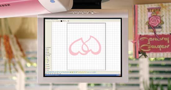
4 1 Introduction This Xyron Wishblade Software software is editing/output software that enables the creation of outline data consisting of simple objects and text, and the output of the created data to the Xyron Wishblade personal cutter. Furthermore, it supports convenient functions that enable the capturing of image data into the software and the automatic creation of registration marks for Print & Cut applications. 1.1 Features The Xyron Wishblade Software has the following features: 1 Supports a function for automatically creating registration marks. 2 Provides a preview display of a printed image, cut image, or combined image. 3 Can load DXF files in AutoCAD R13 format. 4 Allows selecting which line color will be recognized by Xyron Wishblade as a solid cut line or dashed cut line. 5 To facilitate weeding of the cut media, the Weed Border function enables automatic cutting of a border when outputting to the Xyron Wishblade. 6 Any object exceeding the Xyron Wishblade's cutting range can be output in multiple pages using the Tiling function when outputting to the Xyron Wishblade. Note: While importing DXF files only the following DXF objects can be loaded: Lines, polylines, splines, circles, arcs, and ellipses. Block-referenced objects or splines, text, and dimension lines cannot be loaded. For details on setting and operating the Xyron Wishblade, please refer to the Xyron Wishblade user's manual. All screens shown in this manual are those of Windows XP 2 Installing Xyron Wishblade Software 2.1 Launching the Start Window Insert the CD included with the Xyron Wishblade into your computer's CD drive. The [Start] window shown below will be displayed. If this window is not displayed, open "My Computer" and double-click "CD Drive". If the window still does not appear, execute "MultiSetup.exe" included in the CD-ROM. 1.2 System Requirements The minimum system requirements to run the software are as follows. Operating System: Windows 2000/Windows XP CPU: Pentium III 600 MHz or higher Memory: 128 MB or more (at least 256 MB recommended) Monitor: 1024 x 768 High color (True Color recommended) Mouse CD-ROM drive Supported cutter: Xyron Wishblade (CC200-20) Supported printers: Windows-compatible printers (inkjet printers recommended) Page 4 of 40
![2.2 Installing Xyron Wishblade Software Click "Install Xyron Wishblade Software" in the [Start] window to launch the Xyron Wishblade Software installer.](/docs-images/90/102644503/images/5-1.jpg "Be sure to close any open Windows applications before installing Xyron Wishblade Software.")

![Click [Next] to proceed. 4 The "Select Program Folder" screen will be displayed. Click [Next] to proceed. Program Folder is the name of a folder displayed in the Windows [Start] menu.](/docs-images/90/102644503/images/5-3.jpg "If you do not want to change the folder, simply click [Next] to proceed. 5 The \"Setup Type\" screen will be displayed. Choose \"Place Icon on Desktop\".")
5 2.2 Installing Xyron Wishblade Software Click "Install Xyron Wishblade Software" in the [Start] window to launch the Xyron Wishblade Software installer. Be sure to close any open Windows applications before installing Xyron Wishblade Software. When the installation of the Xyron Wishblade Software software has been completed, installation of the Xyron Wishblade Controller and the Xyron Wishblade driver will be performed automatically. Installation procedure 1 When the installer is launched, the screen shown below is displayed first. If you want to change the folder, click the [Browse] button and select a folder. Click [Next] to proceed. 4 The "Select Program Folder" screen will be displayed. Click [Next] to proceed. Program Folder is the name of a folder displayed in the Windows [Start] menu. If you do not want to change the folder, simply click [Next] to proceed. 5 The "Setup Type" screen will be displayed. Choose "Place Icon on Desktop".Click [Next] to proceed 2 The "License Agreement" screen will be displayed. Carefully read the provisions of the agreement, and click [Yes] to continue the installation. 3 The "Choose Destination Location" screen will be displayed. Page 5 of 40

6 6 When the system has finished copying files, a "Install Shield Wizard Complete" screen is displayed. 3 Basic Operations This chapter describes the basic Xyron Wishblade Software operations, from launching the software application to cutting. Note: The term "media" as used in the body of this manual refers to paper, film, and other materials to be cut or printed on. 3.1 Launching and Exiting Click [Finish] to complete the installation. 7 When the installation of this program has been completed, the installer will then proceed to install the Xyron Wishblade Controller and the Xyron Wishblade driver. Launching When this software has been installed in your computer, "Xyron Wishblade Software" is added to "All Programs" in the [Start] menu. Click [Start] [All Programs] [Xyron Wishblade] [Xyron Wishblade Software] to start up the software. Exiting To exit, click "Exit" in the [File] menu. Page 6 of 40
![3.2 Initial Steps First, create a new file for designing the artwork to be printed and/or cut. 1 Creating a new file Choose "New" from the [File] menu to display the [Document Settings] window.](/docs-images/90/102644503/images/7-1.jpg "Set the \"Document Size\" according to the size of the document to be output. Next, choose the \"Orientation\".")
7 3.2 Initial Steps First, create a new file for designing the artwork to be printed and/or cut. 1 Creating a new file Choose "New" from the [File] menu to display the [Document Settings] window. Set the "Document Size" according to the size of the document to be output. Next, choose the "Orientation". If you are going to use a printer to print out the artwork and then cut it on the Xyron Wishblade, select the Use Registration Marks" check box. If you are only going to perform cutting, leave the check box deslected. Click the [OK] button to create the new file. 2 Setting the output destination Choose "Output Preferences" from the [File] menu to display the [Output Preferences] window. This concludes the initial steps. Specify "Printer" and "Xyron Wishblade". For "Printer", select the printer driver to be used to print. "Xyron Wishblade" is displayed when the Xyron Wishblade driver is installed in your computer. There is normally no need to change this setting. If "Xyron Wishblade" is not displayed, perform the Xyron Wishblade setup procedure. 3.3 Cutting Text Outlines This section describes the procedure for drawing a character string and then cutting its outline (text border). 1 Disabling the "Use Registration Marks" setting 2 Entering a text string Go to Edit/ Registration mark settings. Deselect the "Use Registration Marks" check box, and then click the [OK] button. Choose "Text" from the [Draw] menu to display the [Text Settings] window. In this window, set the "Font", "Width", "Height", "Angle", and other parameters, and then enter the text string to be drawn. Select the "Outline" check box. Click the [OK] button. Page 7 of 40

8 The text string will be displayed at the cursor position. Left-click at the position at which the text string is to be placed. If the check box "Use Mouse to Set Angle" has been selected in the [Text Settings] window, proceed to determining the angle of the character string. As the mouse is moved, the angle of the character string changes. Left-click at the angle to be entered. At this time, if you hold down the [Shift] key while moving the mouse, the string angle will be changed in 45-degree increments. Making the cut line settings Choose "Output Preferences" from the [File] menu to display the [Output Preferences] window. Choose the [Cutting Settings] tab in this window, and click the [Cutline Settings] button. The [Cutline Settings] window will be displayed. Confirm that the color for the outline of the text string is selected, and that "Solid Cut Line" is selected for "Cutline". Then, click the [OK button]. Note: All of the colors used are automatically added to the "Cutting Conditions" list. Deselect the colors that are not used for the cut line. 3 Previewing the output image Choose "Preview" from the [File] menu to display the [Preview] window. Choose "Cut" from the [View] menu, and preview the cut line of the image to be output to (to be cut by) the Xyron Wishblade. To exit Preview, choose "Close" from the [Output] menu. 4 Outputting to the Xyron Wishblade A) Launching the Xyron Wishblade Controller Choose "Cut" from the Xyron Wishblade Software [File] menu and then click [OK] in the "Output to Wishblade" window to display the Xyron Wishblade Controller. The Xyron Wishblade Controller is the window where cutting conditions for the Xyron Wishblade are set. B) Test Plotting To avoid wasting media, we recommend performing test plotting before cutting new or modified design for the first time. Test plotting enables the Xyron Wishblade to actually draw solid lines using a pen (ball-point pen) where cutlines suppose to be to determine whether the cut data created is output correctly. B1) Mount a pen (ball-point pen) in the Xyron Wishblad e, and choose "Pen" from the "Media Type" drop-down list on the Xyron Wishblade Controller screen. B2) Load the media (a sheet of A4 or letter size copy paper can be used here) for test plotting. B3) Use the [Blade Position] buttons on the Xyron Wishblade Controller screen to move the pen to the position where test plotting will be performed, and then click the [Set Origin] button. (If the current position is satisfactory, simply proceed to the next step). Press the [Cut...] button on the Xyron Wishblade Controller screen to start drawing the cut line(s). Note: When you have confirmed that the cut data is drawn correctly, perform test cutting. If the cut data is not correctly drawn, check the design and cut data settings again. Page 8 of 40
9 C) Test Cutting Always perform test cutting when any media is to be cut for the first time or the media to be cut (paper or vinyl film) is changed. The media used for test cutting should be the same media that will actually be cut. C1) Choose the media to be cut from the "Media Type" dropdown list on the Xyron Wishblade Controller screen. C2) Attach the blade adjustment cap, in the color displayed in the Xyron Wishblade Controller, to the blade holder, and then mount the blade holder in the Xyron Wishblade. Note: If you are using the "cutting mat", please refer t o the Xyron Wishblade User's Manual for details on how to mount the blade holder. The media will actually be cut during Test Cutting operation. Use the [Blade Position] buttons on the Xyron Wishblade Controller screen to move the blade to a position that does not overlap the area where you want to cut your design, e.g. in the corner or near the edge. Do not click the [Set Origin] button at this time. (Refer to the test plot drawn as described in the preceding section to find an area for test cutting that does not overlap your design.) Check the result of the test cutting. If the media is not cut correctly (excessively or insufficiently cut), adjust the length of the blade protruding from the blade holder (referring to the Xyron Wishblade User's Manual) or use "Adjust Settings" on the Xyron Wishblade Controller screen to determine the conditions for obtaining the best cutting result. D) Setting the origin Before data is cut by the Xyron Wishblade, the reference point for the cutting area (the origin) can be changed. Origin represents a reference position in the design from which all coordinates are calculated. Cursor coordinates can be observed in the lowerright corner of the Xyron Wishblade Software window while design is opened. In landscape orientation, the origin is at the left rear of the Xyron Wishblade when viewed from the front. In portrait orientation, it is at the right rear of the Xyron Wishblade as viewed from the front. That position is output so that it corresponds to the lower left corner of the Xyron Wishblade Software document. D1) Use the [Blade Position] buttons on the Xyron Wishblade Controller screen to move the blade to the position to be used as the origin. D2) When the position to be used as the origin is reached, click the [Set Origin] button on the Xyron Wishblade Controller screen. That position becomes the origin. The "Orientation" setting selection determines the orientation of the design with respect to the origin position. Please refer to the drawing of the Xyron Wishblade in the upper-right corner of the Xyron Wishblade Controller screen. 5 Cutting Upon completion of the Xyron Wishblade Controller operations, output the cut line to the Xyron Wishblade by clicking [Cut...] button in the lower-right corner of the Xyron Wishblade Controller screen. The Xyron Wishblade will begin cutting the outline. Note: For details on using the Xyron Wishblade and the Wishblade Controller, please refer to the Xyron Wis User's Manual. 3.4 Cutting a Text String Placed Inside the Ellipse Xyron hblade This section describes the procedure for printing an object consisting of a text string placed inside an ellipse, and then cutting the contour of that object. To cut the contours of a printed object, the registration marks must be printed along with the object. Here, we'll create registration marks first, and then draw an ellipse. Note: Registration marks are the alignment marks printed around the image to ensure that the positions of the printed image and the cut line match when a printer is used to print out an image and then a cutting plotter used to cut a contour around it. The registration marks are shaped like the letter "L," and are placed at three locations enclosing the printed image. Depending on the printer model, the printable area and the printing positions with respect to the media may vary slightly. The cutting plotter reads the registration marks in order to confirm the position of the printed image and then performs cutting at the correct position. When using registration marks, a fixed area around each registration mark, shaded in the design area of Xyron Wishblade Software, can't be printed. When registration marks are used, therefore, make sure the object to be printed, such as a picture or text string, does not interfere with the areas shown in green in the figure below. However, cut data can be output even for the green areas. Page 9 0f 40
![Registration Mark settings First of all, create a new data file. Type", and then click the [Modify Color] button to select the color with which the ellipse is to be filled.](/docs-images/90/102644503/images/10-3.jpg "Next, to create registration marks, choose \"Registration Mark Settings\" from the [Edit] menu to display the [Registration Mark Settings] window.")
10 Registration Mark settings First of all, create a new data file. Type", and then click the [Modify Color] button to select the color with which the ellipse is to be filled. Next, to create registration marks, choose "Registration Mark Settings" from the [Edit] menu to display the [Registration Mark Settings] window. Select the "Use Registration Marks" check box, and set the origin and other parameters of the registration marks. Note: For details on setting registration marks, please refer to Section 4.10, "Registration Mark Settings Window". 1 Creating an ellipse Drawing an ellipse Choose "Ellipse" from the [Draw] menu, and left-click at the point where the center of the ellipse is supposed to be. Drag the mouse away from the center point. An ellipse will be displayed as the mouse is moved. Reshape the ellipse as desired, and click the mouse button again. Setting the line color of the ellipse With the ellipse that you drew selected, choose "Line Settings" from the [Draw] menu to display the [Line Settings] window. Click [Modify...] in the "Color" section to display the "Color Settings" window, and select the desired line color. Fill settings With the ellipse that you drew selected, choose "Fill Settings" from the [Draw] menu to display the [Fill Settings] window. Choose "Solid" or "Gradient" for "Fill Note: For details on gradient use, please refer to "Gradient" in Section 4.13, "Fill Settings Window". 2 Entering a character string Entering a text string Choose "Text" from the [Draw] menu to display the [Text Settings] window. In this window, set the "Font", "Width", "Height", and other parameters, and then enter the text string (the Outline check box must be deselected). Click the [OK] button. The text string will be displayed at the cursor position. Move the text string into the ellipse, determine the position at which the text string is to be placed, and then left-click the mouse. Setting the text color To change text color, with the text string selected, choose "Line Settings" from the [Draw] menu to display the [Line Settings] window. Click [Modify...] in the "Color" section, and select the desired text string (line segment) color. (Be sure to select a color that is not being used for the cut line.) Adjusting the text string Choose "Select" from the [Draw] menu, and then click the desired text string to display a border enclosing the text string. In this state, the position or height of the text string can be changed. After making the change(s), click any blank space on the screen to deselect it. Note: For details on editing the position or size of an object, please refer to "Select" in Section 4.1.4, "Draw Menu", and to Section 4.15, "Position Window". Page 10 of 40

11 The screen should look like the one shown below. The screen should look like the one shown below. The red line drawn outside the blue ellipse is the line to be cut (cut line). 3 Creating a cut line Drawing a cut line Create a cut line by drawing another ellipse around the existing one. Choose "Ellipse" from the [Draw] menu, and left-click at the center point of the existing ellipse. An ellipse will be drawn as the mouse is moved. Reshape the ellipse as desired, and left-click the mouse button once again. Setting the color of the cut line With the cut line ellipse selected, choose "Line Settings" from the [Draw] menu to display the [Line Settings] window. Click [Modify...] in the "Color" section, and select the desired color for the cut line (a color that is not used in the print data). Red was selected for the cut line in the example below. Fill Settings With the ellipse for the cut line selected, choose "Fill Settings" from the [Draw] menu to display the [Fill Settings] window. Choose "Transparent" for the "Fill Type". Note: In the screen shot, the cut line is drawn in a slightly enlarged size for easy identification. The cut line can be drawn much closer to the outside contour of the blue ellipse than shown here. Moreover, if the border of the ellipse (the black line in this example) is unnecessary, the border can be specified as the cut line. 4 Making the cut line settings Choose "Output Preferences" from the [File] menu to display the [Output Preferences] window. Choose the [Cutting Settings] tab in this window, and click the [Cutline Settings] button. The [Cutline Settings] window will be displayed. Confirm that the color specified for the cut line in (4) - b above is selected, and that "Solid Cut Line" is selected for "Cutline". Then, deselect all other colors. Page 11 of 40
![In addition, choose the [Print Settings] tab in the [Output Preferences] window, deselect the "Print Cut Lines" check box, and click [OK].](/docs-images/90/102644503/images/12-1.jpg "If the \"Print Cut Lines\" check box is selected, the cut line will also be printed when printing is performed. Note: For details on Output Preferences, please refer to Section 4.")
12 In addition, choose the [Print Settings] tab in the [Output Preferences] window, deselect the "Print Cut Lines" check box, and click [OK]. If the "Print Cut Lines" check box is selected, the cut line will also be printed when printing is performed. Note: For details on Output Preferences, please refer to Section 4.7, "Output Preferences Window". 5 Previewing the output image Select "Preview" from the [File] menu. Switch between "Print" and "Cut" in the [View] menu, and confirm the image to be printed and the image to be cut. Check that all the registration marks will be printed. If they will not be printed, choose "Registration Mark Settings" from the [Edit] menu to display the [Registration Mark Settings] window, and then change the location of the registration marks in this window as required.. 6 Output to the printer Choose "Print" from the [File] menu to display the [Print] window. After confirming the content, click the [OK] button to print. Note: For details on operating the printer, please refer to the instruction manual for your printer. 7 Output to the Xyron Wishblade Perform the same operations performed in Step (5), "Outputting to the Xyron Wishblade", of Section 3.3, "Cutting Text Outlines", from "a Launching the Xyron Wishblade Controller" to "b Test plotting" and "c Test cutting". As registration marks are used here, follow the procedures described below. 8 Position alignment (Read registration marks) and cutting After checking the printed results, load the media to be cut in the Xyron Wishblade. Check that the side printed with "Feed This Side First" between the registration marks is facing the Xyron Wishblade, feed the media into the Xyron Wishblade up to the specified position, and then press the Xyron Wishblade's Standby switch. Click the [Cut...] button at the lower-right corner of the Xyron Wishblade Controller screen. The Xyron Wishblade will automatically begin reading the registration marks, and will then cut the outline. Note: If the "Print Media Insertion Direction" checkbox has been deselected in the "Registration Mark Settings" window, printing will not be performed. For details on using the Xyron Wishblade and the Xyron Wishblade Controller, please refer to the Xyron Wishblade User's Manual. 3.5 Cutting the Contour of a Printed Image This section describes the procedure for loading and printing an image file, and cutting the contour of the image. Note: The term "image data" refers to the data from an image file that has been loaded into Xyron Wishblade Software. The term "image file" refers to a data file consisting of pictures or photos (BMP, TIF, JPEG and the like). Here, we'll create registration marks first, and then load an image file. 1 Registration Mark settings First, create a new data file. Next, to create registration marks, choose "Registration Mark Settings" from the [Edit] menu to display the [Registration Mark Settings] window. Note: For details on setting registration marks, please refer to Section 4.10, "Registration Mark Settings Window". 2 Loading and adjusting an image Loading an image file Choose "File" from the [Insert] menu to display the [Load File] window. In this window, specify the file to be imported. An image border will be displayed on the screen. Determine the location at which the image is to be placed, and then left-click. Page 12 of 40
![Adjusting the image been selected in the example below) and then click the [OK] button.](/docs-images/90/102644503/images/13-1.jpg "Fill settings With the rounded rectangle for the cut line selected, choose \"Fill Settings\" from the [Draw] menu to display the [Fill Settings] window.")
![Choose "Transparent" for "Fill Type" and then click the [OK] button. The screen should look like the one shown below.](/docs-images/90/102644503/images/13-2.jpg "If the image data has small squares attached to its four corners, the image data is in the selected state. If it is not selected, choose \"Select\" from the [Draw] menu and click on the image.")
13 Adjusting the image been selected in the example below) and then click the [OK] button. Fill settings With the rounded rectangle for the cut line selected, choose "Fill Settings" from the [Draw] menu to display the [Fill Settings] window. Choose "Transparent" for "Fill Type" and then click the [OK] button. The screen should look like the one shown below. If the image data has small squares attached to its four corners, the image data is in the selected state. If it is not selected, choose "Select" from the [Draw] menu and click on the image. When it is in this state, the image can be moved and/or scaled. Note: For details on editing the position or size of an object, please refer to "Select" in Section 4.1.4, "Draw Menu", and to Section 4.15, "Position Window". 3 Creating a cut line Drawing a cut line Create a cut line with which to cut the contour of the loaded image. Choose "Rounded Rect." from the [Draw] menu, and then left-click at the top left of the image, at a slight distance away from the image. When the mouse is moved, a rounded rectangle is displayed. Move the mouse to the lower right of the image until the image is enclosed by the rectangle, and then left-click once again to complete the rectangle. Note: [Polygon], [Circle], or other tools can also be used, in addition to Rounded Rect., to draw cut lines. Setting the color of the cut line With the rounded rectangle for the cut line selected, choose "Line Settings" from the [Draw] menu to display the [Line Settings] window. Click the [Modify Color] button, select the desired color for the cut line (red has The red line drawn around the image is the cut line. For demonstration purposes, the cut line is shown slightly larger than it's really is. The cut line can actually be created much closer to the image border than shown here. Note: To cut out a pasted image, with the image selected, click [Clip Image] in the [Edit] menu and then select a closed form tool such as a rectangle. For details, refer to "Clip Image" in Section 4.1.2, "Edit Menu". Cut line settings Choose "Output Preferences" from the [File] menu to display the [Output Preferences] window. Choose the [Cutting Settings] tab in this window, and click the [Cutline Settings] button. The [Cutline Settings] window will be displayed. Confirm that the color selected for the cut data in (3)-b above is selected, and that "Solid Cut Line" is selected for "Cutline". In addition, select the [Print Settings] tab of the [Output Preferences] window, and deselect the "Print Cut Lines" check box. If the "Print Cut Lines" check box is Page 13 of 40
![selected, the cut line will also be printed when printing is performed. Note: For details on the [Output Preferences] window, please refer to Section 4.7, "Output Preferences Window".](/docs-images/90/102644503/images/14-1.jpg "1 Output Previewing the output image Click [Preview...] in the [Output Preferences] window.")
14 selected, the cut line will also be printed when printing is performed. Note: For details on the [Output Preferences] window, please refer to Section 4.7, "Output Preferences Window". 1 Output Previewing the output image Click [Preview...] in the [Output Preferences] window. Switch between "Print Image Only" and "Cut Image Only" in the [View] menu, and confirm the image to be printed and the image to be cut. Output to the printer Choose "Print" from the [File] menu to display the [Output to Printer] window. After confirming the content, click the [OK] button to print. Note: For details on operating the printer, refer to the instruction manual for your printer. Output to the Xyron Wishblade Perform the same operations described in step (8), "Output to the Xyron Wishblade", in Section 3.4, "Cutting a Text String Placed Inside the Ellipse". 3.6 How to Trace and Cut an Outline of an Image This section describes the procedure for loading an image file, tracing an outline of the image, and then cutting the image by pasting in a cut line. Note: The term "image file" refers to a data file consisting of pictures or photos (BMP, TIF, JPEG and the like). Here, we'll create registration marks first, and then load an image file. 3 Tracing an outline Tracing an outline With the image selected, choose "Get Outline" from the [Edit] menu to open the {Auto Trace} window and display the selected image. 1 Registration Mark settings Perform the same operations as those performed in Step (1), "Registration Mark Settings" of Section 3.5, "Cutting the Contour of a Printed Image". 2 Loading and adjusting an image Perform the same operations as those performed in Step (2), "Loading and adjusting an image" of Section 3.5, "Cutting the Contour of a Printed Image". Set the Threshold, Thickness and other parameters, and then click the [Convert to Outline] button to convert the displayed image to an outline. Page 14 of 40

15 Note: For details on how to trace the outline, please refer to Section 4.9, "Auto Trace Window". Pasting the outline as a cut line Select "Paste then Exit" to past the outline as a cut line in the selected image. Setting the color of the cut line Perform the same operations as those performed in Step (3) - b, "Setting the color of the cut line" of Section 3.5, "Cutting the Contour of a Printed Image". Cut line settings Perform the same operations as those performed in Step (3) - d, "Cut line settings" of Section 3.5, "Cutting the Contour of a Printed Image". 4 Output Perform the same operations as those performed in Step (4), "Output" of Section 3.5, "Cutting the Contour of a Printed Image". 3.7 For Easy Operation Shortcuts are available for the following operations. Dragging with the right mouse button held down to specify an area. Areas can also be displayed in the preview screen in the same way by dragging with the right mouse button held down. Pressing the [F2] key displays the entire medium. Pressing the [F3] key during an enlarged display enables the Move mode. The cursor changes to the shape of a hand, allowing you to scroll the screen in any direction. Hold down the left mouse button, and drag the mouse in the direction in which the screen is to be moved. Press the [F3] key again to exit Move mode. Page 15 of 40

![A folder list and a preview screen are shown on the left side of the [Thumbnails] window. Saved GSD designs and DXF files in a specified folder are shown on the right side of the window.](/docs-images/90/102644503/images/16-2.jpg "Double-clicking the displayed image allows the file of that image to be loaded. To close the [Thumbnails] window, click the [x] button at the upper right corner of the window.")
16 4 Function Details 4.1 Main Window Load DXF Loads DXF files in AutoCAD R13 format. The DXF objects that can be loaded are limited to line segments, polylines, splines, circles, arcs, and ellipses. Note: The term "DXF file" refers to an AutoCAD file format. Thumbnail Browser Calls up the [Thumbnails] window. A folder list and a preview screen are shown on the left side of the [Thumbnails] window. Saved GSD designs and DXF files in a specified folder are shown on the right side of the window. Double-clicking the displayed image allows the file of that image to be loaded. To close the [Thumbnails] window, click the [x] button at the upper right corner of the window. Note: The term "Thumbnail" refers to a file represented by its reduced image. Close Closes the design that is currently being worked on File Menu New Creates a new design. When "New" is chosen, the [Document Settings] window is displayed. Set the parameters of the media according to the size and orientation of the design to be created, and then click the [OK] button. Note: For details on the [Document Settings] window, please refer to Section 4.2, "Document Settings Window". Open Opens a saved design. When [Open] is chosen, the [Open] window is displayed. After selecting the file to be opened, click the [Open] button to open the selected file. Page 16 of 40 Save Saves the currently opened design file preserving existing file name. Save As When "Save As" is selected, the [Save As] window is displayed. Specify the save location, specify a file name, and then click the [Save] button to save the file. Document Settings Displays the [Document Settings] window. Note: For details on the [Document Settings] window, please refer to Section 4.2, "Document Settings Window". Preferences Displays the [Preferences] window. Note: For details on the [Preferences] window, please refer to Section 4.3, "Preferences Window".
![Preview Displays an output image of the design to be printed or to be cut. Note: For details on Preview, please refer to Section 4.4, "Preview Display". Print Displays the [Print] window.](/docs-images/90/102644503/images/17-1.jpg "Note: For details on the [Print] window, please refer to Section 4.5, \"Output to Printer Window\". Xyron Wishblade Displays the [Output to Xyron Wishblade] window.")
17 Preview Displays an output image of the design to be printed or to be cut. Note: For details on Preview, please refer to Section 4.4, "Preview Display". Print Displays the [Print] window. Note: For details on the [Print] window, please refer to Section 4.5, "Output to Printer Window". Xyron Wishblade Displays the [Output to Xyron Wishblade] window. Note: For details on the [Output to Xyron Wishblade] window, please refer to Section 4.6, "Output to Xyron Wishblade Window". Output Preferences Displays the [Output Preferences] window in which general settings for output to the printer or Xyron Wishblade will be made. Note: For details on the [Output Preferences] window, please refer to Section 4.7, "Output Preferences Window". Exit. Closes the Xyron Wishblade Software program Edit Menu Undo Reverts the immediately preceding editing operation. Redo Re-executes the most recent operation that has been reverted by "Undo". Cut With a form, text, or image selected, click [Cut...] to cut the selected object from the screen. Copy With a form, text, or image selected, click [Copy] to prepare the selected object for copying. Paste Pastes the cut or copied object. When [Paste] is clicked after an object is cut, the object is restored at its original position. When [Paste] is clicked after an object is copied, the border color of the copied object changes to yellow. Select that object by left-clicking on it and dragging it. A copy of the same object will appear. Move it to the desired position and then left-click. Delete Deletes a selected object. Mirror Creates a mirror image of the selected object. Both Horizontal Mirror and Vertical Mirror can be used. Bring to Front... Moves a selected object to the front of all objects on the screen. If filled objects overlap each other, select one to be placed at the front and click [Bring to Front]. Send to Back Moves a selected object to the rear of all objects on the screen. If filled objects overlap each other, select one to be placed at the rear and click [Send to Back]. Group Grouping allows multiple objects to be handled as one object. To group objects, hold down the [Shift] key while clicking on the objects to be included in a group. In this way, multiple objects can be selected at the same time. While in this state, click [Group]. A rectangle enclosing the multiple objects selected will appear. The objects enclosed in that rectangle can be edited by moving or deleting them as one object. When a picture comprised of multiple objects is created, group those objects so that they can then be easily moved together. Ungroup Ungroups grouped objects. To ungroup a grouped object, select a group to be ungrouped and click [Ungroup]. Page 17 of 40

18 Rotate Image Rotates an image 90 degrees each time it is clicked. Images can be rotated using three rotate commands: "Rotate 90 CCW", "Rotate 180 ", and "Rotate 90 CW". Clip Image Clips an image. 1 Use "Import File" from the Insert menu to load image data. 2 While the image data is selected, select the "Clip Image" check box. 3 The Clipping mode is entered. Select a closed shape such as Square, Polygon, Closed Spline, or Ellipse to draw a shape on the image to be cut out. 4 Upon completion of drawing, click outside the image. The image that is cut out in the form of the drawn shape will be displayed. Note: If the clipping shape fully encloses the image, the entire image will be cut out. Get Outline Displays the [Auto Trace] window. Note: For details on the Auto Trace function, please refer to Section 4.9, "Auto Trace Window". Registration Mark Settings Displays the [Registration Mark Settings] window. Note: For details on the [Registration Mark Settings] window, please refer to Section 4.10, "Registration Mark Settings Window". Registration marks cannot be used at the same time as the Weed Border function. Grid Settings The term "grid" refers to a grid of solid lines or dots displayed on the screen, which serve as a guide for plotting. Note: For details on the [Grid Settings] window, please refer to Section 4.11, "Grid Settings Window" View Menu Zoom Out Move Fit Changes the display range of the design currently being worked on, along with the display scale, so that the entire media can be viewed. Zoom In Enlarges the display of the data currently being worked on. Reduces the display of the data currently being worked on. Clicking [Move] selects move mode, and clicking it again deselects it. In Move mode, the cursor changes to the shape of a hand, allowing the screen to be scrolled by dragging using the mouse, and allowing the entire region of the media to be viewed. Note: "Move" can be used only when the media is display enlarged view. When the entire media is being displ displayed range cannot be moved. Tool Bar ed in ayed, the Allows each tool bar in the main window to be shown or hidden. When the mouse cursor is placed over the "Tool Bar," five menu commands are listed: "Standard Tools", "Edit Tools", "Draw Tools", "Line Tools", and "Fill Tools". Click on any tool to display it. The displayed tool is flagged by a check mark. Note: Each of the tool buttons is assigned the functions selected from the menu, allowing any of these commands to be invoked by clicking on the tool button. The assigned function of a tool button is displayed as a Tool Tip (simple explanation) when the mouse cursor is placed over the tool button for a few seconds. Status Bar Allows the status bar to be shown or hidden. The status bar is located at the bottom of the main window, and displays the status and a simple explanation of each function. Registration Marks Specifies whether to display registration marks on the screen. Usable only when the "Use Registration Marks" check box in the Registration Mark Settings is selected. Page 18 of 40

19 Note: For details on registration marks, please refer to Section 4.10, "Registration Mark Settings Window". Print Area The "print area" is a printable range specified according to the media size on the [Print Settings] tab of the [Output Preferences] window, not including the margins specific to the printer. When the "Print Area" is selected, the range that can be print is displayed. The inner part enclosed with lines is the range that can be print. Cut Area Shows or hides the cut area. The cut area is the area indicated by the thin red lines on the screen. Note: Data that is outside the red lines will not be cut. View Grid Displays a grid. Note: The term "grid" refers to a grid of solid lines or dots displayed on the screen, which serves as a guide for drawing. Snap to Grid When "Snap to Grid" is selected, placing or moving of a shape aligns it with a grid by snapping the red handle with the grid intersection. Note: For details on the grid, please refer to Section 4.11, "Grid Settings Window" Draw Menu Select This is the tool for selecting a previously drawn shape. When a shape is selected, small square and/or triangle handles are displayed around it. In this state, the operations described below can be performed. Changing position When the mouse cursor is placed over the shape, the cursor will change to the shape of a hand. The position of the shape can be changed by dragging it in this state. Editing the shape When the mouse is placed on a small black square or triangle, the cursor changes in shape to a bidirectional arrow. Dragging the mouse in this status enables resizing with the width-to-height ratio locked. To enable resizing with the width-toheight ratio unlocked, drag the mouse while holding down a [Shift] key. Rotating the shape When the shape is clicked again, corner handles turn to small circles. When the mouse cursor is placed over a circle handle, the cursor will change shape to a bidirectional arrow ring. The shape can be rotated by dragging it in this state. Note: Imported images cannot be rotated this way. For details on rotating images, please refer to "Rotate Image" in Section 4.1.2, "Edit Menu". Nor can images be rotated when a line segment or image and a shape are grouped together, or when an image and a shape are selected simultaneously. Edit Point This is the tool for moving one of the bend points of a shape to change its form. The effect of the [Edit Point] tool varies with each shape. Polyline, polygon, spline, and closed spline Moving Anchor Point: When one of these shapes is clicked, a black square handle is displayed at each bend point, so dragging a handle, after left-clicking on it to select, allows the bend point to be moved as desired. Page 19 of 40
20 Add Anchor Point: Right-clicking on line of the shape allows to add bend point at the position of a click. Additional bend points allow more flexibility in changing shape of an object. Right-clicking on a point allows the point to be deleted. Note: For splines and closed splines, a point cannot be moved to the same coordinate as that of the point immediately preceding or following it. Arc: When an arc is clicked, small black squares are displayed at both ends of it, allowing the start or end point of the arc to be changed. (The center and radius of the arc are fixed during the procedure.) Note: When another shape (line segment, text, rectangle, circle, ellipse, image, or grouped shape) is clicked, an object selection tool is invoked. Page 20 of 40 Text Selects the tool for creating a text string. Follow the procedure specified below to create a text string. 1 Select the [Text] tool to display the [Text Settings] window. 2 In the [Text Settings] window, make the necessary settings, enter text string and then click the [OK button]. 3 The entered text string will be displayed at the side of the cursor. Move it to the desired location and click to specify the position. Note: For details on the [Text Settings] window, please refer to Section 4.14, "Text Settings Window". Line Selects the tool for creating a line segment. Follow the procedure specified below to create a line segment. 4 Select the [Line] tool. The cursor will change to the shape of a cross. 5 Click on the start point to specify it. 6 Click on the end point to specify it. Note: If the [Shift] key is held while clicking on a point; the position that can be specified as the end point will be limited to an angle in 45-degree increments from the start point. Straight Line Selects the tool for creating a continuous line. Follow the procedure specified below to create a series of connected straight lines. 1 Select the [Straight Line] tool. The cursor will change to the shape of a cross. 2 Click on the start point to specify it. 3 Sequentially click on passage points to specify them. 4 Double-click at the position that is to be the end point. Note: If you hold down the [Shift] key while clicking on a point, the position that can be specified as a passage point or the end point will be limited to a direction in 45-degree increments from the immediately preceding point. Curved Line Selects the tool for creating a curved Line. Follow the procedure specified below to create a curved line. 1 Select the [Curved Line] tool. The cursor will change to the shape of a cross. 2 Click on the start point to specify it. 3 Sequentially click on passage points to specify them. (Adjacent points are linked with a curved line.) 4 Double-click at the position that is to be the end point. (Before specifying the end point, at least two points including the start point must be specified.) Note: Passage points and the end point cannot be entered at the same coordinate as that of the immediately preceding point. Arc Selects the tool for creating an arc. Follow the procedure specified below to create an arc.
21 1 Select the [Arc] tool. The cursor will change to the shape of a cross. 2 Click to specify the position of the center point of a circle including the arc to be created. 3 As the mouse is moved, a circle is displayed around the center point specified above. The distance by which the mouse cursor is moved from the center is the radius of the circle. When the circle is of the desired size, click to confirm. The point at which you've clicked is the start point of the arc. 4 Move the mouse to draw an arc, and click at the end position to specify it. Note: If you hold down the [Shift] key while specifying the end position of the arc, the arc can be drawn in increments of 45 degrees. Rectangle Selects the tool for creating a rectangle. Follow the procedure specified below to create a rectangle. 1 Select the [Rectangle] tool. The cursor will change to the shape of a cross. 2 Click at one of the corners of the rectangle to be created to specify it. 3 Click at the opposite corner of the rectangle to specify it. Note: If you hold down the [Shift] key while clicking, a square can be created. Rounded Rect Selects the tool for creating a rounded rectangle. Follow the procedure specified below to create a rounded rectangle. 1 Select the [Rounded Rect.] tool. The cursor will change to the shape of a cross. 2 Click at one of the corners of the rounded rectangle to be created to specify it. 3 Click at the opposite corner of the rounded rectangle to specify it. Note: Immediately after a rounded rectangle is created, a green circle is displayed in it. Dragging that circle allows the roundness of the rectangle to be adjusted. If you hold down the [Shift] key while dragging, a square with rounded corners can be created. Polygon Selects the tool for creating a polygon. Follow the procedure specified below to create a polygon. 1 Select the [Polygon] tool. The cursor will change to the shape of a cross. 2 Click at one of the corners of the polygon to be created to specify it. 3 Sequentially click at the successive corners of the polygon to specify them. 4 Double-click at the last corner of the polygon. Note: When square handles are displayed at each bend point of the polygon immediately after its creation, the handles can be moved in order to finely adjust the shape of the polygon. In addition, the [Edit Anchor Point] button can be used to finely adjust the polygon later. If you hold down the [Shift] key while specifying points, the specifiable position will be limited to a direction in 45-degree increments from the immediately preceding point. Circle. Selects the tool for creating a circle. Follow the procedure specified below to create a circle. 1 Select the [Circle] tool; the cursor will change to the shape of a cross. 2 Click to specify the center point of the circle to be created. 3 As the mouse is moved, a circle is displayed centering around the point specified above. The distance by which the mouse is moved from the center point determines the radius of the circle. When the circle is of the desired size, click to finish. Page 21 of 40
22 Ellipse Selects the tool for creating an ellipse. Follow the procedure specified below to create an ellipse. 1 Select the [Ellipse] tool. The cursor will change to the shape of a cross. 2 Click to specify the center point of the ellipse to be created. 3 As the mouse is moved, an ellipse is displayed centering round the point specified above. When the mouse is moved in the vertical direction, the ellipse is enlarged in the vertical direction; when you move the mouse in the horizontal direction, the ellipse is enlarged in the horizontal direction. Note: If you hold down the [Shift] key while dragging, the ellipse will become a circle. Closed Spline Selects the tool for creating a closed spline. Follow the procedure specified below to create a closed spline. 1 Select the [Closed Spline] tool. The cursor will change to the shape of a cross. 2 Click at any point to start a closed spline. 3 Click at another point to specify it. When the mouse is moved, the displayed spline becomes looped. 4 Specify successive passage points to draw a closed spline as desired. 5 Double-click at the last point of the closed spline to finish. Note: Passage points and the end point cannot be entered at the same coordinate as that of the immediately preceding point. Templates Templates such as hearts that are often used are stored here. These shapes can be freely called up and used in any design, and the called up shapes can be edited in the same way as drawn shapes. Follow the procedure specified below to call up the shapes. 1 Select the [Templates] tool to display the shapes stored in Xyron Wishblade Software. 2 Select the shape you want to use, and then left-click it. 3 The selection window closes, and a frame representing the size of the shape is displayed next to the mouse cursor. 4 Move the cursor to the position at which the shape is to be placed, and then click to finish. Line Settings Displays the [Line Settings] window to set line types, line widths, and line colors. If this window is opened while a shape is selected, it changes the settings of the selected shape. If this window is opened while no shapes are selected, the line settings are reflected on the shape to be created hereafter. Note: For details on the [Line Settings] window, please refer to Section 4.12, "Line Settings Window". Fill Settings Displays the [Fill Settings] window for setting fill of closed shapes. If this window is opened while a shape is selected, it changes the settings of the selected shape. If this window is opened while no shapes are selected, settings are reflected on the shape to be created hereafter. Note: For details on the [Fill Settings] window, please refer to Section 4.13, "Fill Settings Window". Text Settings Displays the [Text Settings] window for setting text fonts and sizes. If this window is opened while a text string is selected, it changes the settings of the selected text string. If this window is opened while no text strings are selected, settings are reflected on the text string to be created hereafter. Page 22 of 40
23 Note: For details on the [Text Settings] window, please refer to Section 4.14, "Text Settings Window". Position Settings Displays the [Position] window to set the positions, sizes, and angles of rotation of shapes. Selecting a shape enables this menu item. Note: For details on the [Position] window, please refer to Section 4.15, "Position Window" Insert Menu Select Source Selects one of the TWAIN drivers for scanners enabled in Windows. Acquire Launches the selected TWAIN driver and captures a raster image from the scanner. After the image has been captured, a rectangle representing the size of the image is displayed next to the cursor. Move the cursor to the position at which the image is to be placed, and then click to finish. File Loads an image file or metafile (WMF file). When "Load File" is selected, the [Open] window is displayed. Select the desired image file or metafile in the [Open] window, and then click the [Open] button to place the loaded image. A rectangle representing the size of the image for loading is displayed next to the cursor. Move the cursor to the position at which the image is to be placed, and then click to finish. Metafile Settings Displays the [Metafile Loading Settings] window. In this window, the display colors of the cutlines embedded into Windows metafile can be changed. Note: For details on the [Metafile Loading Settings] window, please refer to Section 4.16, "Metafile Loading Settings Window" Window Menu Cascade This command rearranges non-minimized windows on top of each other. Tile Horizontal This command rearranges non-minimized windows by aligning them horizontally on the screen. Tile Vertical This command rearranges non-minimized windows by aligning them vertically on the screen. Arrange Icons. This command rearranges minimized windows by aligning them with the lower left corner of the screen Help Menu Opens this manual. Xyron Wishblade Software hints Opens a Tips window for the Xyron Wishblade Software. User's Manual Support Information Assuming connection to the Internet, this command launches the web browser and opens the Xyron web site. ( About Displays the version information of the Xyron Wishblade Software software Xyron Wishblade Logo Clicking the [Xyron Wishblade] icon at the lower right corner of the screen displays the Xyron Wishblade Web site. Page 23 of 40
![4.2 Document Settings Window Displayed by selecting "Document Settings" from the [File] menu, this window enables setting of the size of the design to be created.](/docs-images/90/102644503/images/24-1.jpg "Orientation Specify \"Portrait\" or \"Landscape\" as the media orientation. Document Size Sets the document size according to the size of the created design.")
24 4.2 Document Settings Window Displayed by selecting "Document Settings" from the [File] menu, this window enables setting of the size of the design to be created. Orientation Specify "Portrait" or "Landscape" as the media orientation. Document Size Sets the document size according to the size of the created design. Editing the document size To edit the document size as desired, select "Specify User Size..." To use other than the designated document size, set the desired width and length here, and select it in "Document Size" drop-down list. The [Specify User Size] window has the following items. Name: Select the name of the document which width and length are to be edited. Although the document name can be edited, a document name that already exists cannot be used. Note: Commas (,) cannot be used in a document name. Width: Specify the document width in 0.01-mm units. (in the range from 1.97 to 8.26 inch) Length: Specify the document length in 0.01-mm units. (in the range from 1.97 to inch) Note: If the document size specified in the [Document Settings] window is larger than the media size set on the [Print Settings] tab of the [Output Preferences] window, selecting the "View Print Area" check box displays the printable areas on the media selected on the [Print Settings] tab side by side so as to cover the entire document size specified in the [Document Settings] window. For example, if a document size of Cutting Mat and Landscape orientation were selected in the [Document Settings] window and Postcard and Landscape orientation selected in the [Output Preferences] tab, the screen will look like the one shown. Use Registration Marks Turns the printing of registration marks on or off. Note: For details on the Registration Marks, please refer to Section 4.10, "Registration Mark Settings Window". 4.3 Units of Measure Window This window is displayed when "Units of Measure" is chosen from the [File] menu. Page 24 of 40

25 Unit Sets the unit used for dimensions. Here, select "mm" or "inch". The unit specified here applies to all dimensions in the Xyron Wishblade Software software. 4.4 Preview Display When "Preview" is selected from the File menu, the main window changes to the preview display mode View Menu Fit Changes the preview display range and scale so that the entire media can be viewed. Zoom In Enlarges the preview display. Zoom Out Reduces the preview display. Print & Cut Changes the target to be displayed in preview. The image to be printed and the image to be cut are displayed on top of each other Output Menu Print Outputs the data currently displayed in preview to a printer. Xyron Wishblade Outputs the data currently displayed in preview to the Xyron Wishblade. Print Image Only Changes the target to be displayed in preview. Only the image to be printed is displayed. If the "Print Cut Lines" check box on the [Print Settings] tab of the [Output Preferences] window is selected, the image is displayed in preview along with the cut line. Therefore, the display is the same as that for Print & Cut. Cut Image Only Changes the target to be displayed in preview. Only the output image for the Xyron Wishblade is displayed. The line that has had its color selected (flagged by a check mark) in "Cutline Settings" is displayed as the cut line. Note: "Cut Image Only" cannot be selected if no colors are selected as cut lines in [Cutline Settings]. Close Closes the preview display mode. Page 25 of 40
![4.5 Print Window This window is displayed when "Print" is selected from the File menu. 4.6 Output to Xyron Wishblade Window This window is displayed when "Cut" is selected from the [File] menu.](/docs-images/90/102644503/images/26-1.jpg "Printer Displays the driver name and the output destination port of the currently selected printer. Copies Specifies the number of copies. It can be specified in the range of 1 to 999.")
. OK The data currently being worked on is output to the printer.")
26 4.5 Print Window This window is displayed when "Print" is selected from the File menu. 4.6 Output to Xyron Wishblade Window This window is displayed when "Cut" is selected from the [File] menu. Printer Displays the driver name and the output destination port of the currently selected printer. Copies Specifies the number of copies. It can be specified in the range of 1 to 999. Page Range Specifies the pages to be printed. Select from two choices: "All" (all pages) or "From" (start page) and "to" (end page). Note: "From" and "to" can only be selected when the data to be printed consists of multiple pages (two or more pages). OK The data currently being worked on is output to the printer. To stop the printing operation, click the [Cancel] button. Xyron Wishblade... Name: Displays the Xyron Wishblade driver "Xyron Xyron Wishblade". Port: Displays the destination port to which to output. Copies Specifies the number of copies. It can be specified in the range of 1 to 999. Note: If, after multiple copies are specified, the [OK] button is clicked to invoke the "Xyron Wishblade Controller" and the [Cut...] button clicked to start output, if the [Abort] button is clicked during output, the Xyron Wishblade Controller stops outputting all the other pages and the Xyron Wishblade Software main window is displayed. Page Range Specifies the pages to be cut. Select from two choices; "All" or "From" and "to." Note: "From" and "to" can only be selected when the data to be cut consists of multiple pages (two or more pages). If, after multiple copies are specified, the [OK] button is clicked to invoke the "Xyron Wishblade Controller" and the [Cut...] button clicked to start output, if the [Abort] button is clicked during output, the Xyron Wishblade Controller stops outputting only the page that was being output when the [Abort] button was clicked, and starts outputting from the next page. Page 26 of 40
![OK Clicking [OK] button invokes the Xyron Wishblade Controller. When [Cut.](/docs-images/90/102644503/images/27-1.jpg "..] button is clicked after the necessary operation is performed using the Xyron Wishblade Controller, it starts outputting to the Xyron Wishblade. To stop output, click [Cancel] button. 4.7.")
27 OK Clicking [OK] button invokes the Xyron Wishblade Controller. When [Cut...] button is clicked after the necessary operation is performed using the Xyron Wishblade Controller, it starts outputting to the Xyron Wishblade. To stop output, click [Cancel] button Always Displayed Items The following explains the items that are always displayed around the [Common Settings], [Print Settings], and [Cutting Settings] tabs of this window. 4.7 Output Preferences Window This window is displayed when "Output Preferences" is selected from the File menu. Printer Displays all of the printer driver names and their ports registered in Windows. Specify the driver to be used for output to a printer. Note: For details on the printer driver, please refer to the user's manual for your printer. Properties Displays a setup window for the printer driver for selected printer. Xyron Wishblade Shows the "Xyron Wishblade" driver name of the cutting plotter Xyron Wishblade and its output destination port. Preview Confirms the content of the Output Preferences that have been set and displays its preview. Output To Printer Confirms the content of the Output Preferences that have been set and displays the [Output to Printer] window. Page 27 of 40
![Output To Wishblade Confirms the content of the Output Preferences that have been set and displays the [Output to Wishblade] window. 4.7.](/docs-images/90/102644503/images/28-3.jpg "2 Common Settings The content of settings made using the [Common Settings] tab are common to the printer and the Xyron Wishblade. Scaling Enlarges or reduces the size of the shape to be output.")

28 Output To Wishblade Confirms the content of the Output Preferences that have been set and displays the [Output to Wishblade] window Common Settings The content of settings made using the [Common Settings] tab are common to the printer and the Xyron Wishblade. Scaling Enlarges or reduces the size of the shape to be output. It can be specified in the range of 25% to 400%. The value specified applies equally to height and width. If 25% is specified, the form will be 1/16 in terms of area ratio. For shapes and texts to be cut, images loaded are enlarged or reduced while maintaining their aspect ratio. The media size will not be changed. Page 28 of 40 Offset The output position is shifted by a specified length. A value for offset in the X (width) direction can be entered in the left-hand input box, and a value for offset in the Y (height) direction can be entered in the righthand input box. The specifiable offset varies according to the media settings and so forth. When outputting to a printer If some data is shifted off the print area as a result of offset, the data may be output separately in multiple sheets of media so that all data will fit in the print area. In such a case, four sheets of media are output. When outputting to the Xyron Wishblade the data included in the cut area is cut. In this case, only the yellow part shown at the right is cut. Weed Border Cuts an outside border corresponding to the dimensions of the document. When a die-cutting sticker is created using media larger than the document to be cut, use this function to peel off only the area required for the sticker on the media. The size of the border is the same as that of the document in the [Document Settings] window. The border can be expanded in the horizontal and vertical directions by a specified size. Specify the size in the range of 0.00 to 1.97 inch. If the size of the border is expanded, the cut data is shifted from the cutting range by an amount equal to the expanded size, as shown below. If a smaller border is required, create cut data for the outer border. If the "Weed Border" check box is selected, the border is cut when the object is cut. Note: This function cannot be used at the same time as the Registration Mark function.


29 4.7.3 Print Settings Cutting Settings Media Size Specify the size of the media to be used for printing. Orientation Specify the direction of the paper (printing direction). Print Cut Lines If this check box is selected, the lines that would be cut in "Output to Xyron Wishblade " are also printed. Rotate 180 degrees If this check box is selected, the object is rotated 180 degrees and then printed. This function is useful when the area for printing registration marks is too small, and even more so when the printer used has a wide trailing margin. Rotate Rotates the data for output. Select from "None", "90CCW", "180", or "90CW". Note: This function cannot be used when registration marks have been set. Eject Media Ejects the media to the front when the system has finished cutting. Tiling Use this function for handling large amounts of data that exceed the size of a single sheet of the media and you want to output it on multiple pages. Page boundaries are always cut. Note: This function cannot be used when registration marks have been set. Media Size Enter the size of the media used. When the media orientation is Portrait In the left-hand box, enter a value in the range of 1.97 to inch In the right-hand box, enter a value in the range of 1.97 to 8.26 inch When the media orientation is Landscape In the left-hand box, enter a value in the range of 1.97 to 8.26 inch In the right-hand box, enter a value in the range of 1.97 to inch Page 29 of 40

![In the [Cutline Settings] window, specify any color for the cutline. Note: For details, please refer to Section 4.](/docs-images/90/102644503/images/30-2.jpg "8, \"Cutline Settings Window\". 4.8 Cutline Settings Window This window is displayed when [Cutline Settings] is clicked on the [Cutting Settings] tab in the [Output Preferences] window.")

30 Overlap Set A value in the range of 0 to 3.94 inch. If a value other than 0 is specified for Overlap, pages are overlapped by a specified value as they are cut. Use this function to create overlapping margins for alignment when separated parts of an object are put together. Cutline Settings Calls up the [Cutline Settings] window. In the [Cutline Settings] window, specify any color for the cutline. Note: For details, please refer to Section 4.8, "Cutline Settings Window". 4.8 Cutline Settings Window This window is displayed when [Cutline Settings] is clicked on the [Cutting Settings] tab in the [Output Preferences] window. Color Lists the colors of the outer lines of all shapes in the design. Because all of the colors used are automatically specified for Solid Cut Line, deselect all other colors, or those that are used for other than Solid Cut Line. Cutline Select the "Solid Cut Line" or "Folding Line" to which a color from the Color list is to be applied. Click on the Cutline parameter for each color, and then make your selection from the pull-down menu. Lines in colors that were specified for "Solid Cut Line" will be cut by the Xyron Wishblade as solid lines. Lines in colors that were specified for "Folding Line" will be cut by the Xyron Wishblade as dashed lines. Click on the entry box area underneath the "Cutline" heading to display a drop-down list. Make your selection from the list. 4.9 Auto Trace Window This window is displayed when "Get Outline" is chosen from the [Edit] menu. When an image is being edited, click the "Convert to Outline" button to display the "Convert to Outline" window. When an outline is being edited, click the "Edit Image" button to display the "Edit Image" window. Convert to Outline - button Edit Image - button Dashed Line Pattern Settings When thick media such as cardboard is folded, a fold line can be added to facilitate folding. Furthermore, as this is a dashed line, it can also be used as a perforation line. Note: The fold line is a dashed line. If the fold line is used for thin media, the creased part of the media will become very weak. Therefore, consider the quality and thickness of the media when using this function. Cut Segment Sets the length of the cut part of the fold line (dashed line) that is to be cut. Specify it in the range of 0.01 to 3.94 inch. Spacing Sets the length of the uncut part of the fold line (dashed line) that is to be left uncut. Specify it in the range of 0.01 to 3.94 inch. Cutting Selection Select the color of the "Solid Cut Line" or "Dashed Line". Only one type of line can be chosen for each color. <When an image is edited> Convert to Outline/Edit Image <When an outline is converted> Click the [Convert to Outline] button to convert the contours of the image data to an outline. Click the [Edit Image] button to enable the image to be edited or redone if the converted outline is uneven or not displayed as expected. Threshold The imported image is converted to monochrome image data, but at that time discrimination between the black and white areas is performed automatically. This discrimination between Page 30 of 40
31 black and white can be adjusted by changing the threshold value. Thickness The contours of the image data are converted to an outline of the specified width thickness only. Outer Frame Only An outline is created using only the image data for the outer frame. Paste then Exit Exits the "Auto Trace" screen and pastes the outline in the layout screen. Note: For further details on the [Auto Trace] screen, please choose "Search Topics" from the [Help] menu then and browse through the displayed topics Registration Mark Settings Window This window is displayed when "Registration Mark Settings" is chosen from the [Edit] menu. Update After the image has been converted to an outline, the outline can be converted once again after making changes to the "Thickness" and "Outer Frame Only" parameters. Show Background Displays the original image in the background of the converted outline. Delete Break Point Deletes any unwanted break points from the lines after the image data has been converted to an outline. Add Break Point Adds break points to the lines after the image data has been converted to an outline. Straight/Curve Changes straight lines to curved lines and vice versa after the image data has been converted to an outline. Page 31 of 40 Note: Registration marks are the alignment marks used to ensure that the positions of the printed image and the cut line match. Registration marks are printed around the image. The registration marks are shaped like the letter "L" and are placed at three locations enclosing the printed image. When using registration marks, a fixed area around each registration mark is not printed. When registration marks are used, therefore, make sure the object to be printed, such as a picture or character string, does not enter the areas shown in green in the figure be low. However, cut data is output even for the green parts of the figure. Use Registration Marks Mode Turns the printing of registration marks on or off. Shows the registration-mark mode. The mode is fixed to "Use three marks", and at this time there are no other choices that can be selected. Use Three Marks Reads three registration marks: one each at the lower left, lower right, and upper left corner of the media. "Use Three Marks" provides a high reading accuracy.
.")
32 Mark Shows the shape of the registration marks. The shape is fixed to "Pattern 2", and at this time there are no other choices that can be selected. Pattern 2 The corner of each registration mark faces the outside of the media. Pattern 2 features a wide cut area. Size. Shows the size of the registration mark ( L ). Width Shows the line width of the registration mark. The line width is fixed to "0.02 inch", and at this time there are no other choices that can be selected. Origin Specifies the position of the first registration mark. With respect to the document specified in Document Settings, the position at which the registration mark is to be set can be determined by specifying offsets from the edges of the document. When the Origin is changed, the first registration mark moves to that position, and the second and third registration marks move to the positions determined relative to the first registration mark by adding the "Distance (1-2)" and the "Distance (1-3)". In the left-hand input box, enter an offset value in the horizontal direction of the document; in the right-hand input box, enter an offset value in the vertical direction of the document. Distance (1-2) Specify the distance between the first and second registration marks. Note: The distance between registration marks is the distance from the corner of one registration mark to the corner of another. Distance (1-3) Specify the distance between the first and third registration marks. Note: The distance between registration marks is the distance from the corner of one registration mark to the corner of another. Origin Distance between points 1-2 Distance between points 1-3 Fit to Document When the first registration mark is moved by changing the "Origin", the second and third registration marks are moved without changing their relative positions with respect to the first registration mark. At this time, if the second or third registration mark reaches the document margin, it is stopped there and the relative distance from the first registration mark is shortened. This action is shown in the layout of the [Registration Mark Settings] window. If the first registration mark is moved and the distance in relation to the second or third registration mark is changed as in this case, click [Fit to Document] to update "Distance (1-2)" and "Distance (1-3)" to the changed values. Print the media loading direction Adds the "Feed This Side First" label and an arrow to the image that is output on the printer to indicate the direction in which the media should be inserted in the Xyron Wishblade Grid Settings Window This window is displayed when "Grid Settings" is chosen from the [Edit] menu. Show Grid Shows a grid. The term "grid" refers to grid of solid lines or dots displayed on the screen, which serve as a guide for drawing. Page 32 of 40


33 Snap to Grid When "Snap to Grid" is chosen, shapes are drawn or moved in increments of grid spacing. If you select "Snap to Grid" before drawing a form, the form will be drawn in increments of grid spacing. If "Snap to Grid" is selected after the shape is created and the shape is moved, the red corner handle is snapped to the nearest grid cross-section Line Settings Window This window is displayed when "Line Settings" is chosen from the [Draw] menu. If this window is opened while a shape is selected, use it to change the settings of the selected form. If this window is opened while no shapes are selected, the default settings of a shape created hereafter are changed. The center of the red square adheres to the grid Line Type Select a line type from the list. Six choices are available for selection: Solid Line, Dotted Line, Dashed Line, Dotted/Dashed Line, Double-Dotted/Dashed Line, and None (the line becomes transparent). Note: If handled as the cutline, the line type specified here is ignored and the data is cut with a solid line. Grid Type Line: Light-gray lines are displayed at equal intervals in the horizontal and vertical directions on the screen. Dot: Light-gray dots are displayed at equal intervals on the screen at grid cross-sections. Grid Spacing Sets the grid interval. Specify it in the range of 0.04 to inch in increments of 0.01 inch (1 to 1000 mm in increments of 1 mm). Line Width Select a line width. A numeric value can also be entered. Specify it in the range of 0.01 to 1.97 inch (0.1 to 50.0 mm). Note: Line Width can only be specified for Solid Line. Modify Opens the [Color] window to enable setting the line color Fill Settings Window This window is displayed when "Fill Settings" is selected from the [Draw] menu. If this window is opened while a shape is selected, use it to change the settings of the selected shape. If this window is opened while no shapes are selected, the default settings of a shape to be created hereafter are changed. Page 33 of 40

.")

34 Fill Type Selects a fill pattern. Gradient - The form is filled with a color gradient. Transparent - The shape doesn't have any fill and is comprised of outlines only. Solid - The form is filled with a single color. Click [Modify Color...] to open the [Color] window, and specify a fill color. Starting Color, Ending Color Two colors of the gradient transition can be specified: one for the start and one for the end of gradient. (To specify colors, use the respective [Modify Color...] buttons to open the [Color] window for the Starting Color and the Ending Color). The gradient displayed in the window consists of the starting color in the center and the ending color at both ends. Move Horizontally Sets the degree of gradient transition in the horizontal direction. As the slider is moved, the color transition border in the window is scrolled to the left or right, depending on the direction of slider movement. Color Window Move Vertically Sets the degree of gradient transition in the vertical direction. As the slider is moved, the color transition border in the window is scrolled up or down, depending on the direction of slider movement. Rotate Sets the rotation of gradient. As the slider is moved to the right, the gradient in the window rotates to the left. As the slider is moved to the left, the gradient in the window rotates to the right. Page 34 of 40
35 4.14 Text Settings Window This window is displayed when "Text" or "Text Settings" is chosen from the [Draw] menu. If "Text Settings" window is opened by clicking "Text" in the [Draw] menu, a box for entering a text string is displayed at the bottom of the window. In this case, the specified text string is created in the document according to the settings made in the dialog box. If this window is opened by clicking "Text Settings" in the [Draw] menu while a text-string object is selected, use it to change the settings of the selected text-string object. If this window is opened by clicking "Text Settings" in the [Draw] menu while no text-string objects are selected, the default settings of a text-string object to be created hereafter are changed. Note: Shown below is a window opened using "Text" in the [Draw] menu. Font Specifies the font of the text. Character Set Specifies the character set of the font. This can normally be disregarded. Some fonts have multiple character sets, allowing different characters to be presented by the selection of a character set. Width Sets the width of one character. Note: With some fonts, the character width may differ for each character. Height Sets the height of one character. Page 35 of 40 Note: With some fonts, the character height may differ for each character. Hold aspect ratio Used when making changes to the text string, this function maintains the font's height-to-width proportions while automatically adjusting the length of the text string. X mirror Creates a mirror of the text string with left/right reversed. Y mirror Angle Creates a mirror of the text string with up/down reversed. Specifies the angle of a text string. Use Mouse to Set Angle If this check box is selected, the angle of a text string can be specified using the mouse after its location is specified at the time of its creation. As the mouse is moved, the placement angle of the character string changes. Left-click at the chosen angle for final placement. At this time, if you hold down the [Shift] key while moving the mouse the angle will change in 45- degree increments. Space Specify the spacing between characters. The spacing should be specified as a percentage (%). To leave a space equivalent to one character, for example, specify 100%. Note: When a proportional font is used, be aware that spaces cannot be left at equal intervals. The term "proportional font" refers to fonts for which the character width differs depending on the character.
. If this check box is selected, Bold and Underline are grayed out and cannot be set. 4.")
36 Italic Bold Sets the style of characters to "italic". Sets the style of characters to "bold". Underline Outline Underlines the characters. Shows the characters in outline form (with only the outlines of characters displayed). If this check box is selected, Bold and Underline are grayed out and cannot be set Position Window This window is displayed when "Position Settings..." is chosen from the [Draw] menu. Position can only be chosen when a shape is selected, allowing the Position, Size, and Angle of Rotation of the selected shape to be set. Position Shows the current position of the selected shape using X and Y coordinates. The small red circle that is displayed when a circumscribed rectangle has been drawn around the shape and that shape is selected is the position of the selected shape. Here, the origin is at the lower-left corner of the document. Numeric values for coordinates can be entered directly from the keyboard to determine the position of the shape. (If "Select Object" has been selected and the mouse cursor is positioned on the screen, the coordinates of the current mouse cursor position are shown at the lower right part of the screen for reference purposes.). Size Shows the size of the selected shape by Width and Height. The size is represented by coordinates. While drawing, if the mouse cursor is moved in the direction away from the origin, a "positive" value is displayed. Conversely, if the mouse cursor is moved in the direction toward the origin, a "negative" value is displayed. Numeric values can be entered directly for "Width" and "Height" from the keyboard to determine the size of the shape. Angle of Rotation Shows the angle of rotation of the selected shape. This angle is counted counterclockwise, up to 360 degrees. A numeric value for angle of rotation can be entered directly from the keyboard Metafile Loading Settings Window This window is displayed when "Metafile Settings" is chosen from the [Insert] menu. If the colors of the cut lines embedded into a Windows metafile are the same as the colors of the drawn lines, the colors of the metafile cut lines can be changed to ensure that the drawn lines do not become the cut lines. The colors displayed for "Solid Cut Line" and "Dashed Line" in the [Extracted Cutline Display Color] section of the window are the colors Page 36 of 40


37 currently specified for "Solid Cut Line" and "Dashed Line". To change the colors, click [Modify Color...] in order to display the [Color] window, select the color to be specified for "Solid Cut Line" or "Dashed Line", and then click [OK]. Test Form? 5 Printing the Registration Mark This chapter describes the procedure for printing the registration mark test form that is used in the Registration Mark Reading Test of the Xyron Wishblade. 1 If the Xyron Wishblade Software in your system was installed without changing the default settings in "Choose Destination Location" and "Destination Folder", the "Xyron Wishblade Software" folder has been created in the location shown below. 2 Choose "Open" from the [File] menu of the Xyron Wishblade Software to display the [Open] window. For Look In, select the [Xyron Wishblade Software] folder confirmed in (1) above. 3 Select the [Adjustment] folder and click [Open]. 4 Select the [Register Mark Test Form] file, and click [Open]. The "Register Mark Test Form" will be displayed. Page 37 of 40
ROBO Master OPS656. USER'S MANUAL MANUAL NO. OPS656m-UM Introduction 1.1 Features System Requirements... 3
 USER'S MANUAL MANUAL NO. m-um-152 Software Usage Agreement... 2 Registered Trademarks... 2 Notes on this Manual... 2 Disclaimer... 2 1 Introduction 1.1 Features... 3 1.2 System Requirements... 3 2 Installing
MANUAL NO. OPS647-UM-151 USER S MANUAL
 MANUAL NO. OPS647-UM-151 USER S MANUAL Software Usage Agreement Graphtec Corporation ( Graphtec ) hereby grants the purchaser and authorized User (the User ) the right to use the software (the Software
Cutting Master ROBO OPS658 USER'S MANUAL MANUAL NO. OPS658-UM-151. Software Usage Agreement...2 Registered Trademarks...2 Notes on this Manual...
 USER'S MANUAL MANUAL NO. -UM-151 Software Usage Agreement...2 Registered Trademarks...2 Notes on this Manual...2 1 Introduction 1.1 Features...3 1.2 System Requirements...3 1.3 Precautions...3 2 Setup
D-Cut Master MANUAL NO. OPS639-UM-153 USER'S MANUAL
 D-Cut Master MANUAL NO. OPS639-UM-153 USER'S MANUAL Software License Agreement Graphtec Corporation ( Graphtec ) grants the user permission to use the software (the software ) provided in accordance with
MIMAKI ENGINEERING CO., LTD.
 For Windows XP/Windows 2000 Cutting Application Software SimpleCut Operation Manual MIMAKI ENGINEERING CO., LTD. D201463 Contents Introduction 1 About this Manual 2 Chapter 1 Installation Procedure 3
MIMAKI ENGINEERING CO., LTD.
 CAMLINK Instruction manual MIMAKI ENGINEERING CO., LTD. TKB Gotenyama Building, 5-9-41, Kitashinagawa, Shinagawa-ku, Tokyo 141-0001, Japan Phone: +81-3-5420-8671 Fax: +81-3-5420-8687 URL: http://www.mimaki.co.jp/
Xyron Wishblade Software Manual (PC)
") Xyron Wishblade Software Manual (PC) Provided By http://www.mybinding.com http://www.mybindingblog.com Xyron Wishblade Create & Cut Software Manual Section 1 Getting Started with Tool Bars 2 Standard Tool
Xyron Wishblade Software Manual (PC) Provided By http://www.mybinding.com http://www.mybindingblog.com Xyron Wishblade Create & Cut Software Manual Section 1 Getting Started with Tool Bars 2 Standard Tool
Designer Reference 1
 Designer Reference 1 Table of Contents USE OF THE DESIGNER...4 KEYBOARD SHORTCUTS...5 Shortcuts...5 Keyboard Hints...5 MENUS...7 File Menu...7 Edit Menu...8 Favorites Menu...9 Document Menu...10 Item Menu...12
LinkMotion and CorelDraw 9, 10, 11, 12, X3, X4, X5, X6, X7 and X8:
 LinkMotion and CorelDraw 9, 10, 11, 12, X3, X4, X5, X6, X7 and X8: After you install LinkMotion software and set up all settings launch CorelDraw software. Important notes: Solustan s LinkMotion driver
Xyron Wishblade Software Manual (Mac)
") Xyron Wishblade Software Manual (Mac) Provided By http://www.mybinding.com http://www.mybindingblog.com Xyron Wishblade Create & Cut Software Manual Section 1 Getting Started with Tool Bars 2 Standard
Xyron Wishblade Software Manual (Mac) Provided By http://www.mybinding.com http://www.mybindingblog.com Xyron Wishblade Create & Cut Software Manual Section 1 Getting Started with Tool Bars 2 Standard
Distributed by Silhouette America, Inc.
 Distributed by Silhouette America, Inc. www.silhouetteamerica.com Table of Contents Silhouette Studio Software Software Usage Agreement. 3 Registered Trademarks.. 3 Disclaimer... 3 About this manual.....
For Windows VISTA /Windows XP Cutting Application Software Simple Studio. Operation Manual MIMAKI ENGINEERING CO., LTD. D
 For Windows VISTA /Windows XP Cutting Application Software Simple Studio Operation Manual MIMAKI ENGINEERING CO., LTD. D201923-11 Contents Introduction 1 About this Manual 3 Chapter 1 Installation Procedure
StickFont Editor v1.01 User Manual. Copyright 2012 NCPlot Software LLC
 StickFont Editor v1.01 User Manual Copyright 2012 NCPlot Software LLC StickFont Editor Manual Table of Contents Welcome... 1 Registering StickFont Editor... 3 Getting Started... 5 Getting Started...
Registered Trademarks The company names and product names described in this manual are registered trademarks of their respective owners.
 silhouettestudio V3 Table of Contents Software Usage Agreement... 2 Registered Trademarks... 2 Disclaimer... 2 About this Manual... 2 1. General Information... 2 1.1 System Requirements...3 1.2 Features
Installation & Operation Guide
 Installation & Operation Guide This manual is the operation guide for Medal Editor. Please refer to this manual to install the software or create medal data used on the processing machine. Items That May
Dr.Engrave USER'S MANUAL
 Dr.Engrave USER'S MANUAL This document is the operation manual for Dr. Engrave for Windows, a program for plate engraving. Contents Introduction... 4 Operating environment... 5 Overview of Dr.Engrave...
Window Designer. Opening Screen: When you start Window Designer, you will see the Opening Screen. Here you will be choosing from 4 options:
 Window Designer Opening Screen: When you start Window Designer, you will see the Opening Screen. Here you will be choosing from 4 options: New Design: Use this option when no pre-built templates are available
A QUICK TOUR OF ADOBE ILLUSTRATOR CC (2018 RELEASE)
") A QUICK TOUR OF ADOBE ILLUSTRATOR CC (2018 RELEASE) Lesson overview In this interactive demonstration of Adobe Illustrator CC (2018 release), you ll get an overview of the main features of the application.
A QUICK TOUR OF ADOBE ILLUSTRATOR CC (2018 RELEASE) Lesson overview In this interactive demonstration of Adobe Illustrator CC (2018 release), you ll get an overview of the main features of the application.
Mint Studio Software Usage Agreement 1
 Software Usage Agreement...1 Registered Trademarks...2 Disclaimer...2 About this Manual...2 1 - General Information...3 1.1 System Requirements...3 1.2 Features Overview...3 1.3 Software File Formats...4
A Study of Angles & Curves
 A Study of Angles & Curves Method 1: Cutting Quilt Shapes/Using the Shapes Tools Open BERNINA CutWork Software. Make sure that Create New is selected. Click Next. Place a dot in front of New Graphic. Select
GCC vinyl cutter, cutting plotter for sign making
 Plotter Setup In "Plotter Setup," you can choose "Plotter List," "Environment," "Pen," and so on. [Plotter list] In this area, you can choose the machine type and set some basic information for your plotter
IMAGE STUDIO LITE. Tutorial Guide Featuring Image Studio Analysis Software Version 3.1
 IMAGE STUDIO LITE Tutorial Guide Featuring Image Studio Analysis Software Version 3.1 Notice The information contained in this document is subject to change without notice. LI-COR MAKES NO WARRANTY OF
Introduction To Inkscape Creating Custom Graphics For Websites, Displays & Lessons
 Introduction To Inkscape Creating Custom Graphics For Websites, Displays & Lessons The Inkscape Program Inkscape is a free, but very powerful vector graphics program. Available for all computer formats
Customisation and production of Badges. Getting started with I-Color System Basic Light
 Customisation and production of Badges Getting started with I-Color System Basic Light Table of contents 1 Creating a Badge Model 1.1 Configuration of Badge Format 1.2 Designing your Badge Model 1.2.1
Sending image(s) to report Click Send Snapshot on any screen in Dolphin3D and choose the Send to Report option
 to report Click Send Snapshot on any screen in Dolphin3D and choose the Send to Report option") Dolphin 3D Reports Sending image(s) to report Click Send Snapshot on any screen in Dolphin3D and choose the Send to Report option Creating a report step by step 1. Generate the desired images in Dolphin3D
Dolphin 3D Reports Sending image(s) to report Click Send Snapshot on any screen in Dolphin3D and choose the Send to Report option Creating a report step by step 1. Generate the desired images in Dolphin3D
The American University in Cairo. Academic Computing Services. Word prepared by. Soumaia Ahmed Al Ayyat
 The American University in Cairo Academic Computing Services Word 2000 prepared by Soumaia Ahmed Al Ayyat Spring 2001 Table of Contents: Opening the Word Program Creating, Opening, and Saving Documents
5. Canvas overview. Cricut Design Space User Manual. Design Panel
 5. Canvas overview The Canvas is where you ll design your projects. On the Canvas, you can add and edit projects, images, and text. You can also set a project template, which doesn t cut but helps you
SHARP Pen Software. Version 2.2 OPERATION MANUAL
 SHARP Pen Software Version 2.2 OPRATION MANUAL Contents Introduction...3 Starting and xiting the Software...4 Pen Software modes and how to start the modes...4 xiting the software...5 Layout of Basic Screen...6
FactoryLink 7. Version 7.0. Client Builder Reference Manual
 FactoryLink 7 Version 7.0 Client Builder Reference Manual Copyright 2000 United States Data Corporation. All rights reserved. NOTICE: The information contained in this document (and other media provided
OPERATION MANUAL MIMAKI ENGINEERING CO., LTD. D200652
 OPERATION MANUAL MIMAKI ENGINEERING CO., LTD. http://www.mimaki.co.jp E-mail:traiding@mimaki.co.jp D200652 About FineCut Thank you very much for purchasing a product of Mimaki. FineCut, a plug-in software
User Manual Version 1.1 January 2015
 User Manual Version 1.1 January 2015 - 2 / 112 - V1.1 Variegator... 7 Variegator Features... 7 1. Variable elements... 7 2. Static elements... 7 3. Element Manipulation... 7 4. Document Formats... 7 5.
LABEL MATRIX TEKLYNX V E R S I O N 8 Q U I C K S T A R T G U I D E
 TEKLYNX LABEL MATRIX V E R S I O N 8 Q U I C K S T A R T G U I D E Note Quick Start Guide The information in this manual is not binding and may be modified without prior notice. Supply of the software
CPM-200 User Guide For Lighthouse for MAX
 CPM-200 User Guide For Lighthouse for MAX Contents Page Number Opening the software 2 Altering the page size & Orientation 3-4 Inserting Text 5 Editing Text 6 Inserting Graphics 7-8 Changing the Colour
Drawing shapes and lines
 Fine F Fi i Handmade H d d Ch Chocolates l Hours Mon Sat 10am 6pm In this demonstration of Adobe Illustrator CS6, you will be introduced to new and exciting application features, like gradients on a stroke
Using SymPrint to Make Overlays, Templates & More...
 Welcome to SymPrint SymPrint is an easy-to-use tool for creating communication overlays, worksheets, classroom activities and more using a modern toolbar and common-sense interface modeled after the programs
Adobe InDesign CS6 Tutorial
 Adobe InDesign CS6 Tutorial Adobe InDesign CS6 is a page-layout software that takes print publishing and page design beyond current boundaries. InDesign is a desktop publishing program that incorporates
Label Design Program Label Artist-II Manual Rev. 1.01
 Label Design Program Label Artist-II Manual Rev. 1.01 http://www.bixolon.com Contents 1. Introduction... 2 2. Supported Operating Systems... 2 3. Features... 3 3-1 Menu... 3 3-1-1 New... 3 3-1-2
OnPoint s Guide to MimioStudio 9
 1 OnPoint s Guide to MimioStudio 9 Getting started with MimioStudio 9 Mimio Studio 9 Notebook Overview.... 2 MimioStudio 9 Notebook...... 3 MimioStudio 9 ActivityWizard.. 4 MimioStudio 9 Tools Overview......
CENTAUR S REAL-TIME GRAPHIC INTERFACE V4.0 OPERATOR S MANUAL
 CENTAUR S REAL-TIME GRAPHIC INTERFACE V4.0 OPERATOR S MANUAL TABLE OF CONTENTS Installation... 6 Introduction to Centaur s real-time Graphic Interface... 6 Computer Requirements... 7 Operating System
User Guide. mk Config
 User Guide mk Config mk Config Register 1.1. CD-Start 4 1.2. Installation 5 1.3. Start 6 1.4. Layout of user interface and functions 7 1.4.1. Overview 7 1.4.2. Part buttons 8 1.4.3. Menus 9 1.4.3.1. Export
Roland CutChoice. Ver. 1 USER S MANUAL
 Roland CutChoice Ver. 1 USER S MANUAL Thank you very much for purchasing the Roland cutter. To ensure correct and safe usage with a full understanding of this product s performance, please be sure to read
OPERATION MANUAL MIMAKI ENGINEERING CO., LTD. D201007
 OPERATION MANUAL MIMAKI ENGINEERING CO., LTD. http://www.mimaki.co.jp E-mail:traiding@mimaki.co.jp D201007 About FineCut Thank you very much for purchasing a product of Mimaki. FineCut, a plug-in software
JASCO CANVAS PROGRAM OPERATION MANUAL
 JASCO CANVAS PROGRAM OPERATION MANUAL P/N: 0302-1840A April 1999 Contents 1. What is JASCO Canvas?...1 1.1 Features...1 1.2 About this Manual...1 2. Installation...1 3. Operating Procedure - Tutorial...2
Corel Draw 11. What is Vector Graphics?
 Corel Draw 11 Corel Draw is a vector based drawing that program that makes it easy to create professional artwork from logos to intricate technical illustrations. Corel Draw 11's enhanced text handling
SMART Meeting Pro 4.2 personal license USER S GUIDE
 smarttech.com/docfeedback/170973 SMART Meeting Pro 4.2 personal license USER S GUIDE Product registration If you register your SMART product, we ll notify you of new features and software upgrades. Register
This guide will help you with many of the basics of operation for your Epson 485wi BrightLink Projector with interactive functionality.
 This guide will help you with many of the basics of operation for your Epson 485wi BrightLink Projector with interactive functionality. If you need further assistance with questions, you can refer to the
Press the Plus + key to zoom in. Press the Minus - key to zoom out. Scroll the mouse wheel away from you to zoom in; towards you to zoom out.
 Navigate Around the Map Interactive maps provide many choices for displaying information, searching for more details, and moving around the map. Most navigation uses the mouse, but at times you may also
Software User's Guide
 Software User's Guide The contents of this guide and the specifications of this product are subject to change without notice. Brother reserves the right to make changes without notice in the specifications
SPRECON-E Display Editor
 SPRECON-E Display Editor Version 2.0b USERS MANUAL 94.2.912.60en 09/2004 ISSUE A page 2 / 61 Business Sector Enery Station Automation (ENA) [Power systems automation] Sprecher Automation GmbH Franckstrasse
Laser Machine User Manual:
 Laser Machine User Manual: OPERATOR ( EasyCut / LaserCut version 5.3 ) v1.0 CTR Laser Machine Operator Manual ( EasyCut version 5.3 ) ~ version 1.0 1 CONTENTS Section 1: Tutorials...5 1.1. How to Cut with
Chapter 6 Formatting Graphic Objects
 Impress Guide Chapter 6 OpenOffice.org Copyright This document is Copyright 2007 by its contributors as listed in the section titled Authors. You can distribute it and/or modify it under the terms of either
2 Solutions Chapter 3. Chapter 3: Practice Example 1
 1 Solutions This section includes the step by step solutions for the practice exercise for the following chapters and sections: Chapter 3 Chapter 4 Chapter 5 Chapter 11: Rainbow Springs sample test Final
Copyright Notice. Trademarks
 Copyright Notice All rights reserved. No part of this publication may be reproduced, stored in a retrieval system, or transmitted in any form or by any means, electronic, mechanical, photocopying, recording,
KODAK Software User s Guide
 KODAK Create@Home Software User s Guide Table of Contents 1 Welcome to KODAK Create@Home Software Features... 1-1 Supported File Formats... 1-1 System Requirements... 1-1 Software Updates...1-2 Automatic
L E S S O N 2 Background
 Flight, Naperville Central High School, Naperville, Ill. No hard hat needed in the InDesign work area Once you learn the concepts of good page design, and you learn how to use InDesign, you are limited
Copyright. Disclaimer
 Q Draw User Manual Copyright Copyright 2010 by BenQ Corporation. All rights reserved. No part of this publication may be reproduced, transmitted, transcribed, stored in a retrieval system or translated
Tutorial 1 Engraved Brass Plate R
 Getting Started With Tutorial 1 Engraved Brass Plate R4-090123 Table of Contents What is V-Carving?... 2 What the software allows you to do... 3 What file formats can be used?... 3 Getting Help... 3 Overview
Craft-N-Cut User s Guide
 Craft-N-Cut User s Guide COPYRIGHT Copyright 2017 Pulse Microsystems, Inc. All rights reserved. This User s Guide and the Craft-N-Cut software are copyrighted by the developer of the software, Pulse Microsystems,
MagicInfo VideoWall Author
 MagicInfo VideoWall Author MagicInfo VideoWall Author User Guide MagicInfo VideoWall Author is a program designed to construct a VideoWall layout and create VideoWall content by adding various elements
Generating Vectors Overview
 Generating Vectors Overview Vectors are mathematically defined shapes consisting of a series of points (nodes), which are connected by lines, arcs or curves (spans) to form the overall shape. Vectors can
Getting Started. In This Chapter
 Getting Started In This Chapter 2 This chapter introduces concepts and procedures that help you get started with AutoCAD. You learn how to open, close, and manage your drawings. You also learn about the
DRAFT. Table of Contents About this manual... ix About CuteSITE Builder... ix. Getting Started... 1
 DRAFT Table of Contents About this manual... ix About CuteSITE Builder... ix Getting Started... 1 Setting up... 1 System Requirements... 1 To install CuteSITE Builder... 1 To register CuteSITE Builder...
GraphWorX64 Productivity Tips
 Description: Overview of the most important productivity tools in GraphWorX64 General Requirement: Basic knowledge of GraphWorX64. Introduction GraphWorX64 has a very powerful development environment in
Exploring the Workspace
 Exploring the Workspace The illustration above shows a typical Create and Cut screen when first loading the software. See the coordinating sections below for an explanation of each shortcut button. Design
Quick Start Guide. ARIS Architect. Version 9.8 Service Release 2
 ARIS Architect Version 9.8 Service Release 2 October 2015 This document applies to ARIS Version 9.8 and to all subsequent releases. Specifications contained herein are subject to change and these changes
Advanced Special Effects
 Adobe Illustrator Advanced Special Effects AI exercise preview exercise overview The object is to create a poster with a unified color scheme by compositing artwork drawn in Illustrator with various effects
A Step-by-step guide to creating a Professional PowerPoint Presentation
 Quick introduction to Microsoft PowerPoint A Step-by-step guide to creating a Professional PowerPoint Presentation Created by Cruse Control creative services Tel +44 (0) 1923 842 295 training@crusecontrol.com
OPS115. Scanning Master Pro Color USER S MANUAL MANUAL NO. OPS115-UM-153
 OPS115 Scanning Master Pro Color USER S MANUAL MANUAL NO. OPS115-UM-153 SOFTWARE USAGE AGREEMENT Graphtec Corporation ( Graphtec ) hereby grants the purchaser and authorized User (the User ) the right
Impress Guide Chapter 11 Setting Up and Customizing Impress
 Impress Guide Chapter 11 Setting Up and Customizing Impress This PDF is designed to be read onscreen, two pages at a time. If you want to print a copy, your PDF viewer should have an option for printing
SHARP Pen Software. Version 2.3 OPERATION MANUAL
 SHARP Pen Software Version 2.3 OPRATION MANUAL Contents Introduction...3 Starting and xiting the Software...4 Pen Software modes and how to start the modes...4 xiting the software...5 Layout of Basic Screen...6
On the Web sun.com/aboutsun/comm_invest STAROFFICE 8 DRAW
 STAROFFICE 8 DRAW Graphics They say a picture is worth a thousand words. Pictures are often used along with our words for good reason. They help communicate our thoughts. They give extra information that
User Guide 701P Wide Format Solution Wide Format Scan Service
 User Guide 701P44865 6204 Wide Format Solution Wide Format Scan Service Xerox Corporation Global Knowledge & Language Services 800 Phillips Road Bldg. 845-17S Webster, NY 14580 Copyright 2006 Xerox Corporation.
How to draw and create shapes
 Adobe Flash Professional Guide How to draw and create shapes You can add artwork to your Adobe Flash Professional documents in two ways: You can import images or draw original artwork in Flash by using
How to...create a Video VBOX Gauge in Inkscape. So you want to create your own gauge? How about a transparent background for those text elements?
 BASIC GAUGE CREATION The Video VBox setup software is capable of using many different image formats for gauge backgrounds, static images, or logos, including Bitmaps, JPEGs, or PNG s. When the software
2D Design. Window. 3D Window. Toolpat h Operati ons. Navigation Homepage. Layer Managemen t. Component Manager. Modeling Tools
 Navigation Homepage Click on the region of the interface you are interested in to navigate to the relevant section of this manual. At the foot of each page is a Navigation Homepage link, click on this
Edupen Pro User Manual
 Edupen Pro User Manual (software for interactive LCD/LED displays and monitors) Ver. 3 www.ahatouch.com Some services in Edupen Pro require dual touch capability. In order to use dual touch, your computer
ARIS Architect QUICK START GUIDE. Version Service Release 7
 ARIS Architect QUICK START GUIDE Version 9.8 - Service Release 7 December 2016 This document applies to ARIS Version 9.8 and to all subsequent releases. Specifications contained herein are subject to change
Software User's Guide
 Software User's Guide The contents of this guide and the specifications of this product are subject to change without notice. Brother reserves the right to make changes without notice in the specifications
Contents. Introduction... 4
 Copyright 2008 Idea Spectrum, Inc. All Rights Reserved. Realtime Landscaping Plus, the Realtime Landscaping Plus logo, Idea Spectrum, and the Idea Spectrum logo are all trademarks of Idea Spectrum, Inc.
Paint/Draw Tools. Foreground color. Free-form select. Select. Eraser/Color Eraser. Fill Color. Color Picker. Magnify. Pencil. Brush.
 Paint/Draw Tools There are two types of draw programs. Bitmap (Paint) Uses pixels mapped to a grid More suitable for photo-realistic images Not easily scalable loses sharpness if resized File sizes are
ezimagex2 User s Guide Version 1.0
 ezimagex2 User s Guide Version 1.0 Copyright and Trademark Information The products described in this document are copyrighted works of AVEN, Inc. 2015 AVEN, Inc. 4595 Platt Rd Ann Arbor, MI 48108 All
Adobe Illustrator CS5 Part 2: Vector Graphic Effects
 CALIFORNIA STATE UNIVERSITY, LOS ANGELES INFORMATION TECHNOLOGY SERVICES Adobe Illustrator CS5 Part 2: Vector Graphic Effects Summer 2011, Version 1.0 Table of Contents Introduction...2 Downloading the
4 TRANSFORMING OBJECTS
 4 TRANSFORMING OBJECTS Lesson overview In this lesson, you ll learn how to do the following: Add, edit, rename, and reorder artboards in an existing document. Navigate artboards. Select individual objects,
Adding Objects Creating Shapes Adding. Text Printing and Exporting Getting Started Creating a. Creating Shapes Adding Text Printing and Exporting
 Getting Started Creating a Workspace Pages, Masters and Guides Adding Objects Creating Shapes Adding Text Printing and Exporting Getting Started Creating a Workspace Pages, Masters and Guides Adding Objects
Quick Start Guide. ARIS Architect. Version 9.7
 ARIS Architect Version 9.7 October 2014 This document applies to ARIS Version 9.7 and to all subsequent releases. Specifications contained herein are subject to change and these changes will be reported
Creative Effects with Illustrator
 ADOBE ILLUSTRATOR Creative Effects with Illustrator PREVIEW OVERVIEW The object is to create a poster with a unified color scheme by compositing artwork drawn in Illustrator with various effects and photographs.
MET 107 Drawing Tool (Shapes) Notes Day 3
 Notes Day 3") MET 107 Drawing Tool (Shapes) Notes Day 3 Shapes: (Insert Tab Shapes) Example: Select on the rounded rectangle Then use the mouse to position the upper left corner and produce the size by dragging out
MET 107 Drawing Tool (Shapes) Notes Day 3 Shapes: (Insert Tab Shapes) Example: Select on the rounded rectangle Then use the mouse to position the upper left corner and produce the size by dragging out
Word 2010 Beginning. Technology Integration Center
 Word 2010 Beginning File Tab... 2 Quick Access Toolbar... 2 The Ribbon... 3 Help... 3 Opening a Document... 3 Documents from Older Versions... 4 Document Views... 4 Navigating the Document... 5 Moving
Virtual MODELA USER'S MANUAL
 Virtual MODELA USER'S MANUAL Virtual MODELA is a program that simulates the movement of the tool on the screen. Contents Contents Part 1 Introduction 1-1 System Requirements... 4 1-2 Overview of Virtual
Panaboard Overlayer User's Guide. Image Capture Software for Electronic Whiteboard (Panaboard)
") Panaboard Overlayer User's Guide Image Capture Software for Electronic Whiteboard (Panaboard) Contents Introduction... 3 Functional Overview... 3 Operation Flow... 3 Abbreviations... 4 Trademarks... 4
Panaboard Overlayer User's Guide Image Capture Software for Electronic Whiteboard (Panaboard) Contents Introduction... 3 Functional Overview... 3 Operation Flow... 3 Abbreviations... 4 Trademarks... 4
-Table of Contents- 1. Overview Installation and removal Operation Main menu Trend graph... 13
 Thank you for buying Data Analysis Software. In order to use this software correctly and safely and to prevent trouble, please read this manual carefully. Notice 1. No part of this manual can be reproduced
Operating Instructions
 Providing presentation solutions V iewer Software Program Operating Instructions NIPPON AVIONICS CO., LTD. 1 This manual describes the functions and operations for conducting presentations using ip Viewer.
SETTINGS AND WORKSPACE
 ADOBE ILLUSTRATOR Adobe Illustrator is a program used to create vector illustrations / graphics (.ai/.eps/.svg). These graphics will then be used for logos, banners, infographics, flyers... in print and
POWERPOINT 2003 OVERVIEW DISCLAIMER:
 DISCLAIMER: POWERPOINT 2003 This reference guide is meant for experienced Microsoft Office users. It provides a list of quick tips and shortcuts for familiar features. This guide does NOT replace training
Label Printing Software BA-300 Version 1.00
 Label Printing Software BA-300 Version 1.00 EN For Windows User s Guide What you can do with the BA-300 Application Using the BA-300 Application Troubleshooting Be sure to keep all user documentation handy
Creative Effects with Illustrator
 ADOBE ILLUSTRATOR PREVIEW Creative Effects with Illustrator AI OVERVIEW The object is to create a poster with a unified color scheme by compositing artwork drawn in Illustrator with various effects and
Adobe Photoshop Sh S.K. Sublania and Sh. Naresh Chand
 Adobe Photoshop Sh S.K. Sublania and Sh. Naresh Chand Photoshop is the software for image processing. With this you can manipulate your pictures, either scanned or otherwise inserted to a great extant.
v Annotation Tools GMS 10.4 Tutorial Use scale bars, North arrows, floating images, text boxes, lines, arrows, circles/ovals, and rectangles.
 v. 10.4 GMS 10.4 Tutorial Use scale bars, North arrows, floating images, text boxes, lines, arrows, circles/ovals, and rectangles. Objectives GMS includes a number of annotation tools that can be used
Roland CutChoice. Ver. 1.1 USER S MANUAL. Thank the user very much for purchasing the Roland cutter.
 Roland CutChoice Ver. 1.1 USER S MANUAL Thank the user very much for purchasing the Roland cutter. S To ensure correct and safe usage with a full understanding of this product s performance, please be
Basic Concepts. Launching MultiAd Creator. To Create an Alias. file://c:\documents and Settings\Gary Horrie\Local Settings\Temp\~hh81F9.
 Page 1 of 71 This section describes several common tasks that you'll need to know in order to use Creator successfully. Examples include launching Creator and opening, saving and closing Creator documents.