MConfigPro Configuration Software. Installation and Operations Manual Section 50
|
|
|
- Amie Hicks
- 5 years ago
- Views:
Transcription

1 MConfigPro Configuration Software Installation and Operations Manual Section 50

2 In order to consistently bring you the highest quality, full featured products, we reserve the right to change our specifications and designs at any time. The latest version of this manual can be found at Warranty - A limited warranty on materials and workmanship for one year is given with this FW Murphy product. A copy of the warranty may be viewed or printed by going to Please read the following information before installing. BEFORE BEGINNING INSTALLATION OF THIS MURPHY PRODUCT: Read and follow all installation instructions. Please contact FW MURPHY immediately if you have any questions.
3 Table of Contents About MConfig Pro... 1 Installing MConfigPro... 1 System Requirements...1 Installation Instructions...2 Installing USB Driver... 4 MConfigPro Application GUI Overview... 6 Launching the Application...6 Menus and Tool Bars...6 Opening Wizard...8 Saving Files...9 Navigating MConfigPro...10 Main Menu List Screen Definitions Version and Security...12 Digital Inputs...14 Digital Outputs...16 Digital Assignments...17 Analog Inputs...18 Analog Outputs...20 Thermocouple...21 Setpoints...22 Global Timers...24 Maintenance Timers...26 Events...27 Startup...29 RPM Controls...30 Control Outputs...31 States...33 Miscellaneous...35 PID...37 Comm Port Settings...39
4 Display Screens...40 Guidelines for Configuring MConfigPro Defining the System...41 System of Protection...42 System of Operation...42 System of Interface...43 Configuration Download Instructions Comm Port Settings...44 Connecting the Centurion controller to PC for Download...44 Initiating Download Sequence...44
5 About MConfig Pro MConfig Pro is a pc-based configuration software for the Centurion controller. The easy-touse interface enables you to modify features of the Centurion such as: sequence of operation set points timers faults displays File transfer utilities for configuration and firmware upgrades are provided so that once the configuration is set, it may be downloaded from your pc to the Centurion via a serial or USB connection. Installing MConfigPro System Requirements A serial port (RS485/232) or USB 1.1 connection is required for transferring the configuration from MConfigPro to the Centurion. While the MConfigPro software will function on any pc or laptop running Windows, it will not perform transfers using the USB driver unless the operating system supports USB. USB supported operating systems include Win98SE, NT, and XP. Serial transfers using standard communication ports (COM1, COM2) should be possible on all Windows platforms. The MConfigPro software and USB driver provide efficient use of your hard drive, using only 3-5 MB of disk space after installation

6 Installation Instructions Follow the steps below to install the MConfigPro software on a pc or laptop. 1. Insert the MConfigPro CD into the CD drive of your computer. The installation menu is displayed. 2. Select Install MConfig Pro from the menu. An Installation Wizard is launched. Click on [Next] to continue. 3. The License Agreement for the product is displayed. You may print the agreement by clicking on the [Print] button displayed beneath the agreement. 4. Once you have read the License Agreement, click the I agree with the terms in the license agreement. then click [Next]. 5. You will be asked for a destination folder for the program. You may accept the suggested directory or you may select a different directory by clicking the [Change] button and browse to the destination folder. Once the destination folder is determined, click [Next] to continue


7 6. The Wizard is now ready to install the program. Click on the [Install] button to begin. This may take several minutes. 7. When the installation is complete, the following screen appears. Click [Finish]

8 Installing USB Driver If you will be using a USB connection device to download the configuration into the Centurion controller, you will need to install the USB driver. Follow the instructions listed below to install the USB Driver. 1. Insert the MConfig Pro CD into the CD drive of your computer. The installation menu is displayed. 2. Select Install USB Driver from the menu. An Install Driver dialog box displays a destination folder for the program. You may accept the suggested directory or you may select a different directory by clicking the [Browse] button to locate the destination folder. 3. Once the destination folder is determined, click [Install]


9 4. The following dialog box will appear to indicate Microsoft has not tested the device driver with the XP operating system. The manufacturer of the royalty-free USB driver has elected not to seek Windows Logo approval. Therefore, you should read the message carefully and understand the impact it may have on critical systems before accepting responsibility for continuing with the installation. Select [Continue Anyway] to continue with the installation of the USB driver. 5. Because the device driver installs two items, the Software Installation dialog box will appear a second time. Select [Continue Anyway]. 6. Once the driver is installed the following dialog box will appear. Click [OK]. 7. From the MConfigPro Installation Menu, select Exit

10 MConfigPro Application GUI Overview This section provides instructions for launching the MConfigPro application, identifies the application features that are accessible through the menu bar, and defines general navigation. Launching the Application To launch the application you may either double-click the MConfigPro application icon located on your desktop, or select MConfigPro Design from the list of programs under your Start menu. The following dialog box is displayed. Click on the [Run] button to launch the application. Menus and Tool Bars NOTE: You may turn off this dialog box from displaying each time you launch the application by de-selecting the check box Always ask before opening this file, located in the lower left corner. The tools provide one-click access to creating a new file, opening an existing file, saving the currently displayed file, or printing the current file. These same functions are available from the File drop-down menu


11 The View drop-down menu provides a list of configurable settings that may be viewed or changed. These same settings are also displayed and available in the Main Menu List window of the user interface when a configuration file is being displayed. Selecting Options displays a dialog box that allows you to select the boards you are using. The Tools menu allows you to upload from or download to the Centurion device. Help provides a link to the FW Murphy website, and will launch an when Contact Us is selected. At this time, there is no online help available


12 Opening Wizard When you click on the new file icon or select File/New from the menus, the Opening Wizard is displayed. It contains three tabs labeled New, Existing, and Recent. The New tab contains several templates to use as guidelines for setting up reciprocating compressors, screw compressors, and pumps. There is also a Blank template to be used for setting up new files and does not contain any pre-configured data. The Existing tab displays the current location where files are being stored. You may select from this list or browse to locate the desired file. The Recent tab displays the most recent files that have been created or updated

13 Saving Files When saving files you may select a file extension specific to the type of equipment you are configuring. This helps to differentiate the file types when you are browsing through the file names. There are four file extensions to choose from..mcp.cfr.cfs.cfp Generic (default) Reciprocating Compressor Screw compressor Pump The default file extension.mcp is used unless a different extension is specified. To select a different extension, click the Save as type: pull-down menu and select the desired extension


14 Navigating MConfigPro Navigating the MConfigPro application interface is versatile and easy. It contains two main windows, or sections of information. The left window contains the Main Menu List of available features and settings available for configuration. This is the same list that is displayed on the View pull down menu. When a new file is created, the Main Menu List is the only window displayed until a process is selected

 are displayed in the upper right section.")

15 Selecting items from the Main Menu List will populate the remaining window with the appropriate information. In most cases, the window will contain three sections of information. In the upper left, a list of processes (A) or options is displayed. When you click on any of these options, the corresponding data fields (B) are displayed in the upper right section. You may click on these fields and enter the appropriate configuration information. The upper right section may also contain helpful guidelines for entering data. The bottom portion (C) of the window contains the same information as the upper right, but in a spreadsheet format containing all the entries listed in the upper section. You may edit either the upper or lower sections as desired


16 Main Menu List Screen Definitions This section provides field definitions for each item in the Main Menu List and can be used as a reference when setting up your configuration files. An example of each screen will be displayed, followed by a table listing all editable fields and their descriptions. Version and Security
17 Field Version Date Time Standard Security Password Non-editable, system generated. The Revision number reflects the version of MConfigPro that created the file or last updated it. If the version is different from the current MConfigPro version, choosing File/Save will update the file version to that of the MConfig Pro version. Non-editable, system generated. Date reflects the date of the last save (or creation date). This is updated with the current date when Save or Saves As is chosen from the File menu. Non-editable, system generated. This Time reflects the time of the last save (or creation time). This is updated with the current Time when Save or Saves As is chosen from the File menu. 15 character description of your choice to identify the configuration. Allows access to all setup menus except the super user menu. Must be zero or range from 100 to and cannot be the same as the Super User Password. Entering a value of 0 disables the password and provides no security. NOTE: Passwords are required for the Centurion display only. Passwords have no function within the Centurion controller. Super User Password Allows access to all setup menus, super user menu and provides additional functions like Reset Fault History which should not be available to most operators. Must be a range from 100 to and cannot be zero or the same as the Standard Security Password

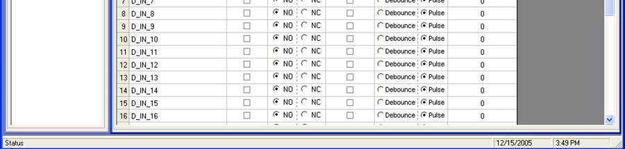
18 Digital Inputs
19 Field Entries are provided for each of the 32 digital input devices. The system generated names may be changed to a more descriptive name of your choice. The field length for description is 17 characters. In Use Active inputs must be set to In Use in order to show up on subsequent configuration screens. Once the input is set to In Use, the entry turns to bolded text. Type NO = Normally Open NC = Normally Closed Enable Delay Check to enable delay. Delay Type Debounce provides a timed condition for processing the digital input. The input must be active for the duration of the delay before it will be recognized as active by the controller application. Once recognized, the digital input must be inactive for the duration of the delay before it will be recognized as inactive by the controller application. This type of signal condition is useful in process conditions such as unstable tank levels. Pulse provides a timed transition condition for processing the digital input. The input will reset the timer each time the input changes condition. If the input does not change conditions in the delay period specified, the controller will signal the event system. Pulse Delay Type also provides tracking counters for number of transitions and last and current pulse duration. This information is available on the Centurion display. Delay (Secs) Number of seconds associated with the delay


20 Digital Outputs Field In Use Type Entries are provided for each of the 10 digital output devices. The system generated names may be changed to a more descriptive name of your choice. The field length for description is 17 characters. Active outputs must be set to In Use in order to show up on subsequent configuration screens. Once the output is set to In Use, the entry turns to bolded text. NO = Normally Open NC = Normally Closed
 10-13 Running Annunciation warm-up, stop (electric motor types need to rely on")
21 Digital Assignments Field State Entries are provided for each of the 11 digital assignments. 2 Start Annunciation start delay Alarm Annunciation - alarm Shutdown Annunciation fault anytime (not state specific) Running Annunciation warm-up, stop (electric motor types need to rely on motor out) 12 Loaded Annunciation run loaded 3 Preheat Output - preheat 4,17 Lube Output pre-lube / post-lube 7 Crank crank only 7-13 Ignition Output crank! crank stop stop 7-13 Fuel Output crank! crank stop stop 9-14 Motor on Output Value List of In Use digital outputs to select from

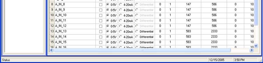
22 Analog Inputs
23 Field In Use Entries are provided for each of the 20 analog input devices. The system generated names may be changed to a more descriptive name of your choice. The field length for description is 17 characters. Active inputs must be set to In Use in order to show up on subsequent configuration screens. Once the input is set to In Use, the entry turns to bolded text. Type 0-5V 4-20mA Differential (calculated) Dec. Choose from 0-3 decimal places. Only selectable for inputs Moving Average Offset Span Min Choices are 1, 2, and 4. Adjust to settle unstable readings. Raw Count Offset, the lowest reading expected from the device. The span from the lowest to highest reading expected from the device. Minimum engineering scale. In most cases, 0 addresses a typical application and is the default value. These values are represented as 0 to 10,000 (0.00 to %). The decimal is implied. For analog inputs, the engineering units are completely at the discretion of the user. An example might be: A PXT-100 would have a Min=0 and Max=100 (PSIG) A PXT-30V30 would have a Min=-14.7 and Max=30 (PSIG) Max Units NOTE: Used to define the input scaled in engineering units. Dual scales are not supported. Maximum engineering scale. These values are represented as 0 to 10,000 (0.00 to %). The decimal is implied. NOTE: Used to define the input scaled in engineering units. Dual scales are not supported. Defines the unit type, span, min, and max. When no other unit of measure is applicable, blank can be selected. PSI F C RPM KPa VDC Amp mv ma Hg WC %


24 Analog Outputs Field Entries are provided for each of the 6 analog output devices. The system generated names may be changed to a more descriptive name of your choice. The field length for description is 17 characters. In Use Active outputs must be set to In Use in order to show up on subsequent configuration screens. Once the output is set to In Use, the entry turns to bolded text. Type 0-20 ma 4-20 ma Offset Raw Count Offset, the lowest reading expected from the device. Span Raw Count Span, the span from the lowest to highest reading expected from the device. Min Minimum engineering scale. In most cases, 0% addresses a typical application and is the default value. Analog outputs use relative terms of Percent (%) for Min and Max because the position is typically 0% output or 100% output and some proportional change in between. Max Maximum engineering scale. In most cases, 100% addresses a typical application and is the default value


25 Thermocouple Field 16 entries are provided for thermocouple devices. The system generated names may be changed to a more descriptive name of your choice. In Use Active devices must be set to In Use in order to show up on subsequent configuration screens. Once the device is set to In Use, the entry turns to bolded text. Type J Type - Typical for most general purpose applications; provides greater accuracy. K Type - High temperature applications; less accuracy. Offset Range is -20 to


26 Setpoints There are 128 configurable setpoints that may be edited. Setpoints further configure variable range input types such as mpu, analog, or thermocouple by defining a threshold, exception or any other out-of-limit event that may require action. Multiple setpoints are often applied to a process and they may be configured as often as needed to meet changing conditions. Common alarm and shutdown setpoints a user might configure include: High Shutdown Low Warning Open Warning High Warning Low Shutdown Setpoints may also be configured for other processes besides alarm and shutdown settings. For example, a setpoint provides a less flexible, but simpler alternative to controlling the pump s start and stop functions
27 Field In Use Signal Type Base GT/LT Value 128 setpoints are provided. The system generated names may be changed to a more descriptive name of your choice. The field length for description is 17 characters. Active setpoints must be set to In Use in order to show up on subsequent configuration screens. Once the device is set to In Use, the entry turns to bolded text. Signal type of setpoint Unused Analog Thermocouple RPM Battery V (tenths) PID Base information is determined by Signal Type selection: Analog = list of in use analog devices to select from Thermocouple = list of in use thermocouple devices to select from RPM = RPM speed source specified in Miscellaneous dialog Battery V (tenths) = External DC voltage supply as measured by the controller represented as XX.X Volts PID = list of in use PID devices to select from. Output from PID 1 thru 4. In reference to value of setpoint. GT = Greater Than LT = Less Than Value of setpoint


28 Global Timers Generally, global timers affect process I/O and the arming of associated events. All event types can be associated with, and locked out by Bx, C, or Sx timers. Field There are 13 available global timers. B1 The first global timer used for delaying an event condition detection. The timer starts in a running State (10-13) depending on which ones have been marked In Use. B1 is also known as the Lockout timer. B2 The second global timer used for delaying an event condition detection. B2 is also known as a secondary Lockout Timer. This timer runs in parallel with B1. C The delay allowing a clear reading before beginning testing for the arming of Class C events. The typical time for most applications is 2 seconds. S1 thru S5 Users have up to five (5) options to assign additional special global timers to signals. The Sx timers begin concurrently with the Bx timers
29 Field Value NF No Flow: The global delay used for delaying the triggering of a no flow event. This global no flow timer is enabled after B1 expires, and begins timing after the expiration of any of the pulse transition times configured in the digital input dialog. Test Time given to allow for maintenance testing of end devices without triggering a fault or shutdown condition. The timer initiates when switched to test mode. Ignition on Delay Time delay before the assigned ignition output turns on. This is typically used to delay ignition until engine crank rollover can occur. Fuel On Delay Time delay before the assigned fuel valve output is turned on. This is typically used to delay fuel until ignition has been turned on. Ignition Off Delay Time delay before the assigned ignition output turns off. This is typically used to burn remaining fuel vapors after the fuel valve is turned off. Timer value

30 Maintenance Timers Field In Use Value (Hours) 10 entries are provided for maintenance settings for timer duration. The system generated names may be changed to a more descriptive name of your choice. The field length for description is 17 characters. Maintenance timers must be set to In Use in order to show up on subsequent configuration screens. Once the timer is set to In Use, the entry turns to bolded text. Timer value units specified in hours

 but does not affect process Message same as alarm except the alarm output is not activated Stop Interrupts process and")
31 Events Field In Use Event Type 128 programmable events are provided. The system generated names may be changed to a more descriptive name of your choice. The description name will be displayed on the Centurion controller when there is an event. The field length for description is 23 characters. Events must be set to In Use in order to show up on subsequent configuration screens. Once the event is set to In Use, the entry turns to bolded text. Event type: Unused Alarm activates alarm banner and alarm output (if assigned) but does not affect process Message same as alarm except the alarm output is not activated Stop Interrupts process and begins shutdown. Once process is stopped, the state engine recycles. (State 1 Panel Ready) Fault SD fault shut down. Interrupts process and begins shutdown. Activates shutdown banner and snapshot page is captured. Faults are first out
32 Field ESD emergency shut down. Same as Fault SD except the process stops and state engine skips all other steps and proceeds to state 19 (Shutdown). Class Event Clear Refers to the Global Timers A always B1 or B2 C S1 thru S5 NF Signal Type Unused Digital Setpoint State Tmr Exp Maint Tmr Exp Sequence NF Timer Exp Signal Action required to clear the fault or event: Requires Ack Requires Reset Self Clearing Signal options are based on Signal Type Unused = unavailable Digital = list of digital in use devices to choose from Setpoint = list of in use setpoints to choose from State Tmr Exp = PANEL READY, STOP ENGINE, or SHUTDOWN Maint Tmr Exp = list of in use maintenance timers to choose from Sequence = None, Overcrank, Crank Fault, PowerUp, Start, Stop, Reset, CAN Comms Fail NF Timer Exp = Global NF Timer
 Digital Input Stop Digital Input Reset Digital Input Use single Setpoint")
 to next In Use state when no shutdown conditions exist.")

33 Startup Field Auto Start Enable Remote on Power Up Remote Mode Enable Digital Input Use single Digital Input to Start/Stop Start (or Start/Stop) Digital Input Stop Digital Input Reset Digital Input Use single Setpoint to Start/Stop Start (or Start/Stop) Setpoint Stop Setpoint When set to Yes, automatically proceeds from state 1 (Panel Ready) to next In Use state when no shutdown conditions exist. Yes or No None or list of In Use digital inputs Yes or No None or list of In Use digital inputs None or list of In Use digital inputs None or list of In Use digital inputs Yes or No None or list of In Use setpoints None or list of In Use setpoints

34 RPM Controls Field Signal Type Value 5 entries are provided for RPM controls. RPM Control Output Cooldown RPM Warmup RPM Wait to Load RPM Run Loaded RPM Signal Type options are based on the RPM type listed in RPM Control Output = Control Output Cooldown RPM = none Warmup RPM = none Wait to Load RPM = none Run Loaded RPM = none Value of Signal Type: For RPM Control Output, a list of In Use Control Outputs For other Signal types, the target RPM control setpoint for that State


35 Control Outputs Control Outputs allow you to define up to eight (8) outputs to augment control not otherwise defined by digital output assignments. These outputs may be defined as analog output, digital output, single pulsed digital output, or two pulsed digital outputs. Note that Control Outputs 1 through 4 are directly related to Proportional Integral Derivative (PID) calculation loops and are further defined in the PID dialog screens. For example, PID 1 is assigned its control from Control Output 1, PID 2 from Control Output 2, and so on
36 Field In Use Ctrl Output Type None Analog 2 Pulsed Digital 1 Pulsed Digital Digital 8 entries are provided for configurable control outputs. The system generated names may be changed to a more descriptive name of your choice. The field length for description is 17 characters. Active outputs must be set to In Use in order to show up on subsequent configuration screens. Once the output is set to In Use, the entry turns to bolded text. Output 1 List of In Use digital or analog outputs. Dependent on Ctrl Output Type selected. Output 2 List of In Use digital outputs. This selection is only available for Ctrl Output Type 2 Pulsed Digital Increase Max on Time Assign value to increase Max On Time. Set limit of maximum on-time Increase OFF Time Incr. Changeover Pulse ON Time Incr. Changeover Pulse OFF Time Decrease Max On time Decrease OFF Time Decr. Changeover Pulse ON Time Decr. Changeover Pulse OFF Time for increase pulses. Set fixed off-time for Increase pulses. Set fixed on-time for single pulse on direction change for increase. Set fixed off-time for single pulse on direction change for increase. Set limit of maximum on-time for Decrease pulses. Set fixed off-time for Decrease pulses. Set fixed on-time for single pulse on direction change for Decrease. Set fixed off-time for single pulse on direction change for Decrease. Increase/Decrease Pulse Settings For Increase Settings Available when the "Ctrl Output Type" is set to 1 or 2 pulsed digital. For Decrease Settings and Changeover Available when the "Ctrl Output Type" is set to 2 pulsed digital
 either times out or meets the permissive, it recycles back to State 6 (Crank Stop).")

 times out or meets the permissive it cycles back to State 11.")
37 States States 6 thru 8 (A) are designated for engine cranking and therefore perform differently than other states. When State 8 (Crank Rest) either times out or meets the permissive, it recycles back to State 6 (Crank Stop). This cycle will continue until a permissive is met in State 7 (Crank). States 10 thru 13 (B) are the Running states. States 11 and 12 work in tandem to perform load and unload functions. When State 11 (Wait to Load) times out or meets the permissive, it then cycles to State 12. When State 12 (Run Loaded) times out or meets the permissive it cycles back to State 11. This cycle will continue until an event or Stop occurs. To prevent the cycle, set the time in State 12 to and do not use a permissive
38 Field State 1. Panel Ready 2. Start Delay 3. Preheat 4. Prelube 5. Start Valve 6. Crank Stop 7. Crank 8. Crank Rest 9. Motor On 10. Warmup 11. Wait to Load 12. Run Loaded 13. Cool Down 14. Stop Engine 15. Motor Off 16. Stop Valve 17. Post Lube 18. Restart Delay 19. Shutdown The state names can be changed. The field length is 13 characters. NOTE: Crank must have a permissive. Crank Stop and Crank Rest will not proceed on to other states. The system generated names may be changed to a more descriptive name of your choice. The field length is 13 characters. In Use Active states must be set to In Use in order to show up on subsequent configuration screens. Once the state is set to In Use, the entry turns to bolded text. Timer (Secs) When set to 65535, there is No Timeout Permissive Type Digital Input Setpoint Timer Expiration Maint Timer Exp NF Timer Exp Permissive When any permissive type is chosen, a list of In Use items for that base is shown. Ctrl Out 1 Value can be 0-100, or if -1, leave alone. Ctrl Out 2 Value can be 0-100, or if -1, leave alone. Ctrl Out 3 Value can be 0-100, or if -1, leave alone. Ctrl Out 4 Value can be 0-100, or if -1, leave alone. Ctrl Out 5 Value can be 0-100, or if -1, leave alone. Ctrl Out 6 Value can be 0-100, or if -1, leave alone. Ctrl Out 7 Value can be 0-100, or if -1, leave alone. Ctrl Out 8 Value can be 0-100, or if -1, leave alone

39 Miscellaneous
40 Field Signal Type Value 13 miscellaneous entries are provided: Number of Crank Attempts Magnetic Input Teeth RPM Source Crank EndZero RPM Error Signal Oil Pressure Source Water Temperature Source Suction Pressure Source Discharge Pressure Source Ignition Off in Crank Rest Fuel Off in Crank Rest Core Temp Adjustment (tenths) Expansion Temp Adjustment (tenths) Temperature Units Signal Type is based on which entry is selected in. Not all entries use signal types. RPM Source = None, Analog, Magnetic Input Crank EndZero RPM Error Signal = None, Digital, Setpoint Oil Pressure Source = None, Analog Water Temperature Source = None, Analog, Thermocouple Suction Pressure Source = None, Analog Discharge Pressure Source = None, Analog Value data is based on which entry is selected in. Not all entries require a value. Number of Crank Attempts number of crank attempts Magnetic Input Teeth number of flywheel teeth Ignition Off in Crank Rest Yes or No Fuel Off in Crank Rest Yes or No Core Temp Adjustment (tenths) adjustment degrees in tenths Expansion Temp Adjustment (tenths) adjustment degrees in tenths Temperature Units C (Celsius) or F (Fahrenheit)

41 PID Up to four (4) Proportional Integral Derivative (PID) calculation loops may be configured in MConfigPro. A PID provides a constant feedback loop, in which the PID can correct for a measured process variable against a desired set point, output the corrective action to the process and wait for and recalculate the next measurement. The ultimate goal of the PID is to reduce the error to zero. During the time a PID is enabled, the PID always overrides control output settings found in the states dialog. Recall that PID 1 assumes control of control output 1, PID 2 assumes control of control output 2, and so on. Field 4 entries are provided to setup PIDs. The system generated names may be changed to a more descriptive name of your choice. The field length for description is 13 characters. In Use Active PIDs must be set to In Use in order to show up on subsequent configuration screens. Once the PID is set to In Use, the entry turns to bolded text. Flag Increase Flag increase on increasing difference Decrease Flag decrease on increasing difference
42 Field Enable Type Not Enabled All States Run Loaded State All Running States Feedback Type None Analog Thermocouple RPM PID Feedback Base Options based on the feedback type. Setpoint The desired goal the target feedback base value. RampTime (250ms) Time interval for the PID to calculate error. Deadband Value around the set point during which the PID will not calculate error. Minimum Output Percentage as minimum output. Maximum Output Percentage as maximum output. Proportional The output value that is proportional to the change of error. Integral To prevent the PID from oscillating or overshooting the set point, assign a value to reset the system to produce zero error, or nudge the process variable to the set point. This value is typically set to zero. Derivative Value to rate of change of error. This value is typically set to zero. MaxRate of Change Percentage rate of change over which would cause harm to the system. Override Type None Digital Setpoint Override Signal Override Ramp Amount Override Ramp Time Override Max Change Options based on the Override Type. Determine the increments in a given direction (positive or negative) that the set point should be altered to regain balanced processes. In the example of the discharge and suction pressure application, this value would indicate how much the PID should resist its goal in reaching the set point. Time interval value to wait before making the next adjustment A maximum allowed change. This represents the total amount of change allowed into or out of the ramp amount from the set point. The maximum change value should be large enough to effect change
 BaudRate Port 2 Value Based on entry")

43 Comm Port Settings Field Modbus Address Port 1 Comm Port 1 Delay Modbus Reply Port 1 (ms) BaudRate Port 1 Comm Port 2 Delay Modbus Reply Port 2 (ms) BaudRate Port 2 Value Based on entry selected in description Comm Port 1 = RS232 or RS485 BaudRate Port 1 = 9600, 19200, 38400, 57600, or Comm Port 2 = RS232 or RS485 BaudRate Port 2 = 9600, 19200, 38400, 57600, or
44 Display Screens
45 Guidelines for Configuring MConfigPro This section provides guidelines for setting up common configuration items in MConfigPro such as inputs, outputs, setpoints, timers, alarms, and events, etc. for pumps, reciprocating compressors, and screw compressors. For detailed screen/field information, refer to the chapter titled Main Menu List - Screen Definitions. There is a logical sequence to follow when configuring the Centurion. These sequences will be explained in four separate topics. They are: Defining the System System of Protection System of Operation System of Interface Defining the System The first step in defining the system is to gather information for setting up your analog and/or digital devices and control outputs. For your convenience, you may want to make a checklist of this information for entering into MConfigPro. Once this information has been entered, it will be available for subsequent configuration options. The following items from the Main Menu List allow you to define the system. Refer to the chapter titled Main Menu List - Screen Definitions for information on field options you will be entering. I/O Scheme Define the I/O scheme of devices you have: Digital Input/Output devices Analog Input/Output devices Control Output Define Control Outputs, based on control type (analog, digital, 1 or 2 pulsed digital) Global Timers What are the manufacturers suggested specifications for protection to create the necessary setpoints? This information can usually be found in the equipment manual that came with the product. Maintenance Timers What are the recommended intervals for maintenance? This information can usually be found in the equipment manual that came with the product
46 System of Protection This portion of the configuration allows you to setup events to define when a system will indicate an alarm, a message, or will be shutdown. It also allows for defining how an alarm is cleared. Shutdowns may be defined by the following types: Stop a controlled stop under normal conditions Fault SD abnormal conditions with minimal consequences (not catastrophic) ESD immediate emergency shutdown The following items from the Main Menu List allow you to define the system of protection. Refer to the chapter titled Main Menu List - Screen Definitions for information on field options you will be entering. Events What steps need to be taken to shutdown equipment on Stop, Fault SD, or ESD conditions? What types of alarms or messages need to be defined and how will they be acknowledged? System of Operation The sequences to be defined for system of operation determine the day-to-day, normal operation of your equipment. The following items from the Main Menu List allow you to define the system of operation. Refer to the chapter titled Main Menu List - Screen Definitions for information on field options you will be entering. Startup What are the procedures for initiating a start? RPM Control Consideration point: If control outputs exist, do they need RPM control? States States reflects all steps from evaluating conditions, to controlling start, stop, and running the equipment. The ideal operating condition is Run Loaded. Miscellaneous The miscellaneous menu option contains various options to be set that don t directly relate to process I/O. They control items such as number of crank attempts and oil pressure source and water temperature source
47 PID PID runs as a parallel process to system of operations. Determine at what point or state type it is enabled. System of Interface This sequence determines the communication port setup for downloading the MConfigPro configuration files. It also determines how information is displayed on the Centurion. The following items from the Main Menu List allow you to define the system of interface. Refer to the chapter titled Main Menu List - Screen Definitions for information on field options you will be entering. Comm Port Settings Determine which type of connection will be used: USB Connection Serial Connection (RS-232 or RS-485) Specify behavior of comm ports. Specify how to represent various information coming from the comm ports. Display Screens This step is only necessary if the system of interface is the Centurion display
48 Configuration Download Instructions Once your configuration files are setup, you may download them to the Centurion controller through either a USB port, or serial port (Com1 or Com2). Comm Port Settings Before you can download files to the Centurion controller, the communication port settings must be established for serial ports Com1 or Com2. [PROCEDURE] Connecting the Centurion controller to PC for Download USB Connection [PROCEDURE] Serial Connection (Com1 or Com2) [PROCEDURE] Initiating Download Sequence [PROCEDURE]
49 MURPHY, the Murphy logo, Centurion, and MConfigPro are registered and/or common law trademarks of Murphy Industries, Inc. This document, including textual matter and illustrations, is copyright protected by Murphy Industries, Inc., with all rights reserved. (c) 2005 Murphy Industries, Inc. Other third party product or trade names referenced herein are the property of their respective owners and are used for identification purposes only
50
Cascade Configuration Tool
 Cascade Configuration Tool Version 1.0.10 Installation and Operations Manual 00-02-0724 01-25-11 Section 40 In order to consistently bring you the highest quality, full featured products, we reserve the
CENTURION Configurable Controller. Installation and Operations Manual Section 50
 CENTURION Configurable Controller Installation and Operations Manual 00-02-0590 10-10-06 Section 50 In order to consistently bring you the highest quality, full featured products, we reserve the right
CENTURION Configurable Controller. Installation and Operations Manual Section 50
 CENTURION Configurable Controller Installation and Operations Manual 00-02-0590 02-09-06 Section 50 In order to consistently bring you the highest quality, full featured products, we reserve the right
Centurion C5 M-VIEW Monochrome LCD (MV-5-C) Operations Manual Section 50
 Operations Manual Section 50") Centurion C5 M-VIEW Monochrome LCD (MV-5-C) Operations Manual 00-02-1031 2019-02-14 Section 50 BEFORE BEGINNING INSTALLATION OF THIS FW MURPHY PRODUCT: Please read the following information before operating
Centurion C5 M-VIEW Monochrome LCD (MV-5-C) Operations Manual 00-02-1031 2019-02-14 Section 50 BEFORE BEGINNING INSTALLATION OF THIS FW MURPHY PRODUCT: Please read the following information before operating
CENTURION - C4 Series Configurable Controller. Installation and Operations Manual Section 50
 CENTURION - C4 Series Configurable Controller Installation and Operations Manual 00-02-0696 2017-12-12 Section 50 FW Murphy has made efforts to ensure the reliability of the Centurion controller and to
MODBUS RTU I/O Expansion Modules - Models C267, C277, and C287. Installation and Operations Manual Section 50
 MODBUS RTU I/O Expansion Modules - Models C267, C277, and C287 Installation and Operations Manual 00-02-0651 09-01-09 Section 50 In order to consistently bring you the highest quality, full featured products,
GSC300 CONFIGURATOR SOFTWARE INTERFACE. Installation and User Manual for the GSC300 Configurator PC Software Interface
 GSC300 CONFIGURATOR SOFTWARE INTERFACE Installation and User Manual for the GSC300 Configurator PC Software Interface File: ConfiguratorRev1.5.2.doc Feb.21, 2006 2 READ MANUAL BEFORE INSTALLING UNIT END-USER
M2500 Engine Controller Configuration Manual
 M2500 Engine Controller Configuration Manual Revision: 08-04-2011 Page 1 Contents 1 Preface... 4 2 Configuration from front panel... 5 2.1 Engine Controller Configuration... 6 2.1.1 RPM settings... 6 2.1.2
PowerView. Model PV-101-A, V2.3 User s Guide Section 78
 PowerView Model PV-101-A, V2.3 User s Guide 10-18-11 00-02-0795 Section 78 In order to consistently bring you the highest quality, full featured products, we reserve the right to change our specifications
PROGRAMMING GUIDE
 www.altroniccontrols.com PROGRAMMING GUIDE DEVIATION FROM THESE INSTRUCTIONS MAY LEAD TO IMPROPER ENGINE/MACHINE OPERATION WHICH COULD WARNING: CAUSE PERSONAL INJURY TO OPERATORS OR OTHER NEARBY PERSONNEL.
SCC Inc. TS Series Application Guide. Technical Instructions. Document No. TS 8000 January 9, Description
 SCC Inc. Application Guide Technical Instructions January 9, 2018 Description The Application Guide includes programming, wiring, and operation examples of the control system for the most common applications.
Quantum HD Release Notes
 Quantum HD Release Notes OS Version 10.17 Released 7-14-2014 To upgrade to OS version 10.17 directly the current OS version must be 10.13 through 10.16. To check the current OS version on the Quantum HD
DE SERIES. Enhanced DE-2500 System Now Available. Programmable Safety Shutdown, Monitoring and Control Products with Analog Input Capabilities
 Enhanced DE-2500 System Now Available DE SERIES Programmable Safety Shutdown, Monitoring and Control Products with Analog Input Capabilities A state-of-the-art family of products specifically designed
GSC400 PC INTERFACE SOFTWARE MANUAL. Installation and User Manual for the GSC400 PC Software Interface
 4016 Quartz Drive Santa Rosa, CA 95405 Phone: 707 539-9003 Fax: 707 539-5212 Email: sales@generatorjoe.net Web www.generatorjoe.net GSC400 PC INTERFACE SOFTWARE MANUAL Installation and User Manual for
Manual# Installation Manual SDU 410. Safety Shutdown Unit
 Manual# 1100641 Installation Manual SDU 410 Safety Shutdown Unit Installation Manual for SDU 410 ~~~ Safety Shutdown Unit Revision 1.0 Revised August 31, 2017 Revision history: Rev. Date Description 1.0
Graphical User Interface V1.0.3
 Graphical User Interface V1.0.3 Application User Guide 2015 MCI Solutions. All rights reserved. 240815-01 www.mcisolutions.ca Page ii Getting Started Table Of Contents Introduction.................................................
TTD Series Configurable Fault Annunciator. Installation and Operations Manual Section 50
 TTD Series Configurable Fault Annunciator Installation and Operations Manual 00-02-0697 2016-08-08 Section 50 In order to consistently bring you the highest quality, full-featured products, we reserve
PowerView. Model PV-101 User s Guide. Rev Catalog Section 78
 PowerView Model PV-101 User s Guide Rev 09-10-08 00-02-0605 Catalog Section 78 In order to consistently bring you the highest quality, full featured products, we reserve the right to change our specifications
Quick Installation Guide
 Manual# 1100274 Quick Installation Guide SDU 410 Safety Unit Quick Installation Guide for SDU 410 Safety Unit ~~~ Revision 1.1 Revised November 10, 2016 Revision history: Rev. Date Description 1.0 04.2012
Series S1501 Selectronic Micro-Controller/Annunciator. Installation and Operations Manual Section 50
 Series S1501 Selectronic Micro-Controller/Annunciator Installation and Operations Manual 00-02-0271 06-16-09 Section 50 In order to consistently bring you the highest quality, full-featured products, we
Series S1501 Selectronic Microcontroller/Annunciator. Installation and Operations Manual Section 50
 Series S1501 Selectronic Microcontroller/Annunciator Installation and Operations Manual 00-02-0819 2015-11-19 Section 50 Please read the following information before installing. BEFORE BEGINNING INSTALLATION
PV101-C Configuration Software V3.2. Installation and Operations Manual Section 78
 PV101-C Configuration Software V3.2 Installation and Operations Manual 00-02-0797 08-18-11 Section 78 In order to consistently bring you the highest quality, full featured products, we reserve the right
1.4 MConfig PC software can be optionally used to upload/download configuration settings to the VRU Pro using RS-485 communication.
 FW Murphy VRU Pro Configuration Guide using MConfig v1.60 February 18, 2016 1.0 General Information 1.1 All VRU Pro controllers have firmware that controls the operation of the controller. The latest version
PF2100 MODBUS LOGGER CARD SYSTEM SPECIFICATION. v1.0 DRAFT Revised Dec 4, 2014 Last Revised by Alex Messner
 PF2100 MODBUS LOGGER CARD SYSTEM SPECIFICATION Revised Last Revised by Alex Messner This page was intentionally left blank. Table of Contents 1 Overview... 2 2 User Interface... 3 2.1 LEDs... 3 2.2 Buttons...
Genset control and protection with safety system
 APPLICATION NOTES Generator Protection Unit, GPU-3 APPLICATION NOTES Genset control and protection with safety system Application description Functional description Wiring I/O lists Basic setup Flowcharts
4848 Reactor Controller
 4848 Reactor Controller 4848 Controller with MCM, PDM and HTM expansion modules installed. The Parr 4843 and 4836 Controllers have been replaced with the new 4848 Controller. This new controller brings
High Motor Current Shutdown High Motor Current Warning Low Motor Current Shutdown Compressor Auxiliary Shutdown
 Important: To upgrade from Quantum HD version 10.21 or earlier to Quantum HD Unity version 10.30 or later requires the flashcard to be changed. These are available through the Baltimore Parts Center, part
PowerView TM Model PV350 and PV380. Operations Manual Section 78
 PowerView TM Model PV350 and PV380 Operations Manual 00-02-0879 2012-11-30 Section 78 In order to consistently bring you the highest quality, full featured products, we reserve the right to change our
Option M2 Configurable engine control cards Multi-line 2 version B SW version 2.4X.X
 Description of options Option M2 Configurable engine control cards Multi-line 2 version 2 4189340482B SW version 2.4X.X Description of options Functional description DEIF A/S Display units Additional functions
RST INSTRUMENTS LTD.
 RST INSTRUMENTS LTD. VW0420 Analog VW Interface Instruction Manual Ltd. 11545 Kingston St Maple Ridge, BC Canada V2X 0Z5 Tel: (604) 540-1100 Fax: (604) 540-1005 Email: Info@rstinstruments.com i VW0420
VALCON EasyWriter Ver1.0E Manual
 VALCON EasyWriter Ver1.0E Manual E05172-K00022-00 Published Dec.2010 Ver3-1.03 HKS Co., Ltd. Revision History Revision Date 2008/12/10 First Edition (Ver3-1.01) 2010/4/2 Second Edition (Ver3-1.02) 2010/12/22
Appendix C: HVAC PRO Modules
 FANs 637.5, 1637.5 Appendix Section Issue Date 0400 APPLICATION NOTE Appendix C: HVAC PRO Modules HVAC PRO Modules...3 Introduction...*3 Key Concepts...*4 ABS VALUE... 6 ADD... 6 ANALOG OUTPUT... 6 AND...
Modbus Bit # Tag Explanation Reg 1=lsb 16=msb
 Modbus Bit # Tag Explanation Reg 1=lsb 16=msb Command/Interaction area. This is a Read/Write area. Commands Explanation 40001 Commands from the MView (Port 1) Commands from the MView (Port 1) 1 Requires
Installation and Configuration Manual
 Manual# 1100288 Installation and Configuration Manual 200 Series DCU 210/208 Engine Panel RP 210 Remote Panel DMU 206 - CANbus Reader Installation and Configuration Manual for the Marine Pro 200 Series
PowerView. Model PV-101-C User s Guide Version Catalog Section 78
 PowerView Model PV-101-C User s Guide Version 3.1 10-11-10 00-02-0718 Catalog Section 78 Table of Contents Introduction... 1 Engine and Transmission Parameters 2 Faceplate Features 3 Navigation and Keypad
OPERATING MANUAL
 www.altroniccontrols.com OPERATING MANUAL DEVIATION FROM THESE INSTRUCTIONS MAY LEAD TO IMPROPER ENGINE/MACHINE OPERATION WHICH COULD WARNING: CAUSE PERSONAL INJURY TO OPERATORS OR OTHER NEARBY PERSONNEL.
User Manual WatchPower
 User Manual WatchPower Management Software for Inverter Table of Contents 1. WatchPower Overview... 1 1.1. Introduction... 1 1.2. Features... 1 2. WatchPower Install and Uninstall... 1 2.1. System Requirement...
PF MODBUS REGISTER MAP. v1.4 Revised Nov 29, 2016
 PF3107-00 MODBUS REGISTER MAP v1.4 Revised TRADEMARKS AND COPYRIGHT All content is subject to copyright and may not be reproduced in any form without the express written consent of the author. 2016 Profire
User Manual. MPPTracker. Management Software for Solar Charge Controller. Version: 1.2
 User Manual MPPTracker Management Software for Solar Charge Controller Version: 1.2 Table of Contents 1. MPPTracker Overview... 1 1.1. Introduction... 1 1.2. Features... 1 2. MPPTracker Install and Uninstall...
SECTION 5 HSLRT6 WINDOWS BASED SETUP PROGRAM REFERENCE
 The Windows based set-up program is menu driven, allowing the user to easily view data, alter setup variables or set machine timing (machine offset, timing signal locations, etc.), using a PC running the
Temperature-Humidity Sensor Configuration Tool Rev. A 1/25/
 Rev. A 1/25/213 172 Contents Contents Temperature-Humidity Sensor Configuration Tool... 3 Read Sensor Screen... 3 Manual Calibration Screen... 4 Register View Screen... 5 Modbus Registers... 6 Reprogram
ADAM-5511 Quick Start
 ADAM-5511 Quick Start Support Firmware 1.01 or above Copyright Notice This document is copyrighted 2001 by Advantech Co., Ltd. All rights are reserved. Advantech Co., Ltd., reserves the right to make improvements
Optidrive Applications Support Library
 Optidrive Applications Support Library Application Note Title AN-ODV-3-038 Related Products Optidrive Eco Overview Level 3 Modbus RTU Control and Register Mapping 1 Fundamental - No previous experience
R7X CONFIGURATOR. (model: R7CON) Users Manual , Minamitsumori, Nishinari-ku, Osaka JAPAN Tel: Fax:
 Users Manual , Minamitsumori, Nishinari-ku, Osaka JAPAN Tel: Fax:") R7X CONFIGURATOR (model: R7CON) Users Manual 5-2-55, Minamitsumori, Nishinari-ku, Osaka 557-0063 JAPAN Tel: +81-6-6659-8201 Fax: +81-6-6659-8510 http://www.m-system.co.jp/ E-mail: info@m-system.co.jp R7CON
R7X CONFIGURATOR (model: R7CON) Users Manual 5-2-55, Minamitsumori, Nishinari-ku, Osaka 557-0063 JAPAN Tel: +81-6-6659-8201 Fax: +81-6-6659-8510 http://www.m-system.co.jp/ E-mail: info@m-system.co.jp R7CON
3690 N.W. 53rd Street Fort Lauderdale, FL SC-2124 SC-2124M. 24 Channel Universal Scanner. Installation and Operation Manual P/N 145F-11902
 3690 N.W. 53rd Street Fort Lauderdale, FL 33309 SC-2124 SC-2124M 24 Channel Universal Scanner Installation and Operation Manual P/N 145F-11902 Rev. 3.30 (c) Copyright 2000, Dynalco Controls All Rights
ExactLogic BACnet Communicating Thermostat EXL01816 Sequence Datasheet
 ExactLogic BACnet Communicating Thermostat EXL01816 Sequence Datasheet DataSheet ev 1.12.307/4.0 Jun 20, 2018 Operating Sequence Standard Occupied During normal occupied operation the display will show
How to install the software of ZNS8022
 How to install the software of ZNS8022 1. Please connect ZNS8022 to your PC after finished assembly. 2. Insert Installation CD to your CD-ROM drive and initiate the auto-run program. The wizard will run
Gas Control Manager Program User Manual (for FloBoss 107)
") Part D301749X012 August 2016 Gas Control Manager Program User Manual (for FloBoss 107) Remote Automation Solutions Revision Tracking Sheet August 2016 This manual may be revised periodically to incorporate
Part D301749X012 August 2016 Gas Control Manager Program User Manual (for FloBoss 107) Remote Automation Solutions Revision Tracking Sheet August 2016 This manual may be revised periodically to incorporate
ViewPower. User s Manual. Management Software for Uninterruptible Power Supply Systems
 ViewPower User s Manual Management Software for Uninterruptible Power Supply Systems Table of Contents 1. ViewPower Overview...2 1.1. Introduction...2 1.2. Structure...2 1.3. Applications...2 1.4. Features...3
Safety Instructions 1-1 Avoid unintended Start General Description 2-2
 Contents Contents 1 Safety and precautions 1-1 Safety Instructions 1-1 Avoid unintended Start. 1-1 2 Introduction 2-1 General Description 2-2 3 Supported Configuration 3-1 Introduction 3-1 Fixed-speed
Centurion PLUS CPC4 Download Guide using C4 File Transfer Utility
 1010537 2010-03-01 Section 50 Centurion PLUS CPC4 Download Guide using C4 File Transfer Utility 1.0 Background 1.1 The Centurion PLUS Control system consists of a Centurion PLUS Core (CPC4-1) and color
Manual# Configuration Manual. 400E Series. DCU 410E Engine Control Unit RP 410E Remote Panel
 Manual# 1006423 Configuration Manual 400E Series DCU 410E Engine Control Unit RP 410E Remote Panel RP 410E DCU 410E Configuration Manual for Marine Pro 400E Series ~~~ DCU 410E Diesel Engine Control Unit
reliable innovation Centurion
 Centurion Key Terms Annunciator Device that monitors for a specific event and indicates (annunciates) that event via numeric codes. Some events may be set to shutdown the equipment being monitored. Fixed
TTD Series Configurable Fault Annunciator. Installation and Operations Manual Section 50
 TTD Series Configurable Fault Annunciator Installation and Operations Manual 00-02-0697 2013-04-22 Section 50 In order to consistently bring you the highest quality, full featured products, we reserve
Metasys Integrator Caterpillar Application
 Application Note Issue Date May, 00 APPLICATION NOTE Metasys Integrator Caterpillar Application Introduction Application Details Component Requirements Vendor Contact Information Design Considerations
MODBUS EXPANSION CARD
 2100 MODBUS EXPANSION CARD MAP v2.1 FOR HARDWARE v2.0 ONLY FOR FIRMWARE v2.0, v4.0, v4.1, v4.3 PF2100 MODBUS EXPANSION CARD MAP v2.1 PROFIRE ENERGY INC. FIRMWARE VERSION HISTORY FIRMWARE VERSION HISTORY
EMS-GC10 Genset Controller. Modbus Communication Mapping Manual Section 75
 EMS-GC10 Genset Controller Modbus Communication Mapping Manual 1311311 2013-10-10 Section 75 In order to consistently bring you the highest quality, full featured products, we reserve the right to change
INSTRUCTION MANUAL FOR GUARDIAN INFINITY SIM PROGRAM
 INSTRUCTION MANUAL FOR GUARDIAN INFINITY SIM PROGRAM Model: INF Firmware 60.xxx Date: July 16, 2008 Page 0 of 29 INDEX 1- INFSIM OVERVIEW:...3 1.1- STARTING THE SOFTWARE:...3 1.2- ESTABLISHING COMMUNICATIONS:...3
User Manual PDUTracker
 User Manual PDUTracker Management Software for PDU Table of Contents 1. Overview... 1 1.1. Introduction... 1 1.2. Features... 1 2. Install and Uninstall... 1 2.1. System Requirement... 1 2.2. Software
GSC400 Series. GSC400 Programmer and PC Interface User Manual
 GSC400 Series GSC400 Programmer and PC Interface User Manual GSC400 Programmer and PC Interface User Manual Full Version File: GSC400 PC Interface Rev1.5.doc, December 2010 2 of 42 Thank You For Purchasing
Service Bulletin SB685. Date: 8/18/2017 TriPac EVOLUTION Communications Update Bulletin Location: TSA Info Central\Service Bulletins
 Service Bulletin SB685 Date: 8/18/2017 Subject: TriPac EVOLUTION Communications Update Bulletin Location: TSA Info Central\Service Bulletins Units: All TriPac EVOLUTION Summary: This bulletin updates and
Operating Instructions Extended Cascade Controller MCO 101
 Operating Instructions Extended Cascade Controller MCO 101 VLT AQUA Drive FC 200 Extended Cascade Controller Option Contents Contents 1. Safety and precautions 3 Safety Instructions 3 Avoid unintended
Modbus Register Map: InRow ACRD60x / ACRC60x
 Modbus Map: InRow ACRD60x / ACRC60x Notes: 1. 16-bit registers (INT16, UINT16, ENUM) are transmitted MSB first (i.e., big-endian). 2. INT32 and UINT32 are most-significant word in n+0, least significant
Comprehensive Modular Genset Controller
 Inteligen Learn More Comprehensive Modular Genset Controller Brief Description The Inteligen is a comprehensive controller for single and multiple generating sets operating in standby or parallel to the
5450 NW 33rd Ave, Suite 104 Fort Lauderdale, FL Fruitland Ave Los Angeles, CA UM Channel Monitor.
 5450 NW 33rd Ave, Suite 104 Fort Lauderdale, FL 33309 3211 Fruitland Ave Los Angeles, CA 90058 UM-600 6-Channel Monitor Version 2 Installation and Operation Manual Rev. G P/N145F-12990 PCO 00007462 (c)
PowerView Model PV101-A, V2.3 Modifications
 PowerView Model PV101-A, V2.3 Modifications The following changes have been made to PowerView 101-A, please read this and keep with the User s Guide. Utilities Menu Information in Software Version and
SolarPower Pro. User s Manual. Management Software for Solar Inverter
 SolarPower Pro User s Manual Management Software for Solar Inverter Table of Contents 1. SolarPower Pro Overview... 2 1.1. Introduction... 2 1.2. Structure... 2 1.3. Features... 3 2. SolarPower Pro Install
32MP Gateway. Overview and Configuration Manual
 32MP Gateway Overview and Configuration Manual 32MP Gateway Overview and Configuration Manual This document is the property of Carrier Corporation and is delivered on the express condition that it is not
U90 Ladder Software Manual. Version 3.50, 6/03
 U90 Ladder Software Manual Version 3.50, 6/03 Table Of Contents Welcome to U90 Ladder... 1 Program Editors... 1 Project Navigation Tree...1 Browse Sequences...1 Printing Documentation...2 Interface Language...
MIST Version 2.0 USER S GUIDE. Preliminary Version. INTRODUCTION...2 General Description...2 Models Available...2
 1 MIST Version 2.0 USER S GUIDE Preliminary Version INTRODUCTION...2 General Description...2 Models Available...2 INSTALLATION...2 Unpacking...2 Mechanical Installation...3 Electrical Wiring...3 Stand-alone
User Manual MPPTracker
 User Manual MPPTracker Management Software for Solar Charge Controller Version: 1.0 Table of Contents 1. MPPTracker Overview... 1 1.1. Introduction... 1 1.2. Features... 1 2. MPPTracker Install and Uninstall...
SNTL300P-PCSUITE interface suite
 yi6508 issue A, 2016-10-06 SNTL300P-PCSUITE interface suite Configuration and Monitoring software for Sentinel 300P automatic switch mode battery chargers Installation and Operation Manual SNTL300P-PCSUITE
Contents 1 Warnings, Cautions, and Notes Description Features... 1
 EnCell Contents 1 Warnings, Cautions, and Notes... 1 2 Description... 1 3 Features... 1 3.1 STANDARD FEATURES... 1 3.2 FRONT PANEL FEATURES... 2 3.2.1 Display... 2 3.2.2 OK LED... 2 3.2.3 FAULT LED...
pco 3 Controller User Manual ASPX Digital Scroll, Air Packaged Chiller For Version MCDSV_A02
 pco 3 Controller User Manual ASPX Digital Scroll, Air Packaged Chiller For Version MCDSV_A02 pco 3 Controller User Manual Introduction The Airstack Chiller is a modular air-cooled chiller composed of
Athena Series RMC Hot Runner Controller Configuration and Operation Manual
 Athena Series RMC Hot Runner Controller Configuration and Operation Manual Athena and CompuStep are registered trademarks, and Multi-Comm and SafeChange are trademarks of Athena Controls, Inc. MODBUS is
InteliDrive Nano. Reference Guide. Engine Controller. InteliDrive Nano. Compact Controller for Industrial Engines. SW version 1.
 InteliDrive Nano InteliDrive Nano Engine Controller Compact Controller for Industrial Engines SW version 1.3, October 2012 Reference Guide Copyright 2012 ComAp s.r.o. ComAp, spol. s r.o. Kundratka 17,
CommandCenter Operator Panel
 CommandCenter Operator Panel Introduction This document describes the different features of the Operator Panel (local or remote) that is used with the Seresco units. Startup Screens When the unit start
User Manual WatchPower
 User Manual WatchPower Management Software for SP Efecto / SP Brilliant (Plus) / SP Initial Table of Contents 1. WatchPower Overview...1 1.1. Introduction... 1 1.2. Features... 1 2. WatchPower Install
ABSTRACT BACKGROUND PSIG 05B3
 PSIG 05B3 Simulating pipeline control systems for operator training David Basnett, Atmos International Ltd, John Lewis, Atmos International Inc. Copyright 2003, Pipeline Simulation Interest Group This
X-618 Public Address and Voice
 X-618 Public Address and Voice Alarm System Commissioning Manual M_XXXXXX_CN_0 Copyright 2012 Honeywell International Inc. All rights reserved. No part of this document may be reproduced in any form without
CORD-XL Dual-Channel Electronic Chart Recorder User s Manual
 CORD-XL Dual-Channel Electronic Chart Recorder User s Manual Rohrback Cosasco Systems Inc. 11841 E. Smith Ave Santa Fe Springs, CA 90670 Tel: (562) 949-0123 Fax: (562) 949-3065 P/N 720701-Manual Rev E
Comm. RS-232. Analog I/O I N P U T S O U T P U T S. I/O Supply. Logic Supply RET RET Fault
 Model 2220 Analog Input / Output Module Installation Guide 2701E 2203 I/O Supply Logic Supply Fault 1 5 9 13 I N P U T S 2220 Digital Out 02 04 06 08 RET RET +24 +24 Out1 Out4 Out5 Out8 Comm. RS-232 1
Quick Start Guide. Variable Speed Drive. Part Number: Issue: 3
 EVC Series Quick Start Guide English Issue 3.book Page 1 Friday, March 11, 2016 1:38 PM Quick Start Guide Variable Speed Drive Part Number: 0478-0335-03 Issue: 3 Original Instructions For the purposes
TABLE OF CONTENTS INTRODUCTION. 3. Analog Input Analog Output Digital Input Digital Output OPERATIONAL DESCRIPITON.. 7 PROGRAMMING AND INITIAL SETUP.
 DIVERSIFIED HEAT TRANSFER SERIES 700 STEAM GENERATOR CONTROLLER INSTRUCTION MANUAL VISIT OUR WEBSITE AT SIGMACONTROLS.COM SERIES 700 DHT STEAM GENERATOR MANUAL 042514 2 TABLE OF CONTENTS INTRODUCTION.
BACVIEW MANUAL Software Version 3.06 INSTALLATION AND OPERATION MANUAL
 BACVIEW MANUAL Software Version 3.06 INSTALLATION AND OPERATION MANUAL 641-K31 1 BACVIEW INSTALLATION AND OPERATION IMPORTANT: This manual is for use with controller ZONE I/O 560 FHP part number 641-224
Data Converter. For 8 Series Mobile Computers. Version 3.02
 Data Converter For 8 Series Mobile Computers Version 3.02 Copyright 2010~2014 CIPHERLAB CO., LTD. All rights reserved The software contains proprietary information of CIPHERLAB CO., LTD.; it is provided
Operating Instructions
 Operating Instructions DE-3000 Series Configurable Safety Shutdown and Control System with Graphing Capabilities Form SOME FEATURES IN THIS MANUAL ARE ONLY APPLICABLE TO DE-3000 FIRMWARE DATED 2014 OR
TRAINING GUIDE LEVEL 3 MODBUS WRITE IMPORT COMMAND
 OleumTechTM TRAINING GUIDE LEVEL 3 MODBUS WRITE IMPORT COMMAND MUST BE FAMILIAR WITH LEVEL 1 TRAINING MATERIALS BEFORE MOVING FORWARD Doc ID# 80-6010-001b TABLE OF CONTENTS 1. WHAT IS NEW WRITE IMPORT
EnCell Battery Cell Monitor
 EnCell Battery Cell Monitor Instruction Manual Model RCM15S12 NERC Compliant YO R U H T PA TO Z O R E W O D N M I T E enchargepowersystems.com sales@enchargepowersystems.com (888) 407.5040 Contents 1 Warnings,
PC PROGRAM INSTRUCTIONS FOR CREST and COPPERFIN MODELS
 FB-CF-PCP_100161018_2000004582_Rev B PC PROGRAM INSTRUCTIONS FOR CREST and COPPERFIN MODELS WARNING This manual must only be used by a qualified heating installer / service technician. Read all instructions,
HMC9000A DIESEL ENGINE CONTROLLER (With J1939 Interface) USER MANUAL SMARTGEN (ZHENGZHOU) TECHNOLOGY CO.,LTD.
 USER MANUAL SMARTGEN (ZHENGZHOU) TECHNOLOGY CO.,LTD.") HMC9000A DIESEL ENGINE CONTROLLER (With J1939 Interface) USER MANUAL SMARTGEN (ZHENGZHOU) TECHNOLOGY CO.,LTD. Chinese trademark English trademark SmartGen make your generator smart SmartGen Technology
HMC9000A DIESEL ENGINE CONTROLLER (With J1939 Interface) USER MANUAL SMARTGEN (ZHENGZHOU) TECHNOLOGY CO.,LTD. Chinese trademark English trademark SmartGen make your generator smart SmartGen Technology
WARNING. TTDJ Series Fully-Configurable Fault Annunciator Installation and Operations Manual
 TTDJ Series Fully-Configurable Fault Annunciator Installation and Operations Manual TTDJ-99062N Revised 04-04 Section 50 (00-02-0412) Please read the following information before installing. This installation
1510A. MTI Instruments, Inc. 325 Washington Avenue Extension, Albany, New York USA Phone: (518) FAX: (518)
 FAX: (518)") Revision 3.1 August 7, 2014 1510A Precision Signal Source Note: Performing a user calibration with the software package will result in an accuracy of 2% at best. A factory cal is required to achieve the
Revision 3.1 August 7, 2014 1510A Precision Signal Source Note: Performing a user calibration with the software package will result in an accuracy of 2% at best. A factory cal is required to achieve the
What is the Carrier ChillerVu series counterflow application?
 Carrier ChillerVu 23XRV Series Counterflow Application Guide CARRIER CORPORATION 2017 A member of the United Technologies Corporation family Stock symbol UTX Catalog No. 11-808-578-01 4/5/2017 Verify that
Genset Controller Unit Model EMS - GC10. Installation Manual Section
 Genset Controller Unit Model EMS - GC10 Installation Manual 00-02-0794 Section 75 2013-01-28 In order to consistently bring you the highest quality, full featured products, we reserve the right to change
PROFIRE PF3100 Modbus Register Map PF
 PF 3100 Modbus Register Map R 0.4 PF3100 Modbus Register Map PF3107-00 solutions@profireenergy.com Page 1 of 12 Table of Contents 1. Introduction... 3 General Information... 3 Configuration... 3 Communications...
User Manual SolarTracker
 User Manual SolarTracker Management Software for Inverter Table of Contents 1. SolarTracker Overview... 1 1.1. Introduction... 1 1.2. Features... 1 2. SolarTracker Install and Uninstall... 1 2.1. System
USER MANUAL. PowerFrame TM Personal. UPS Monitoring Software
 USER MANUAL PowerFrame TM Personal UPS Monitoring Software www.bxterra.com 1 TABLE OF CONTENTS Introduction... Structure... Applications... Features... System Requirements... Supported Operating Systems...
NORDSON CORPORATION AMHERST, OHIO USA
 CanWorks Operator Interface Tracking PLUS for CanWorks Systems with SM-2 Spray Monitors User Guide Part 1018132A NORDSON CORPORATION AMHERST, OHIO USA 2002 Nordson Corporation. All rights reserved. CanWorks,
GSC400 Series. GSC400 Programmer and PC Interface User Manual
 GSC400 Series GSC400 Programmer and PC Interface User Manual GSC400 Programmer and PC Interface User Manual Full Version File: GSC400 PC Interface Rev1.2.doc, August 2009 2 of 33 Amendments Issue Section