PV101-C Configuration Software V3.2. Installation and Operations Manual Section 78
|
|
|
- Charleen Stafford
- 6 years ago
- Views:
Transcription


1 PV101-C Configuration Software V3.2 Installation and Operations Manual Section 78
2 In order to consistently bring you the highest quality, full featured products, we reserve the right to change our specifications and designs at any time. The latest version of this manual can be found at Please read the following information before installing. BEFORE BEGINNING INSTALLATION OF THIS MURPHY PRODUCT: Read and follow all installation instructions. Please contact FW MURPHY if you have any questions.
3 Contents Introduction... 1 Installing V3.2 Software Configurator... 1 System Requirements... 1 Installation of SAP Crystal Reports... 1 PV101-C Installation Instructions... 5 Getting Started... 9 Launching the Application... 9 PV101-C Configurator Screen Navigating the Configurator Screen Entering a New Configuration File Create and Load Config Files Connecting Your PV101-C to Your Computer Installation Screen and Field Definitions Field Sorting Configuration General Settings Languages Overview Languages Selections Parameters Measured Value Parameter Configuration State Parameter Configuration Gear Parameter Configuration Engine Configuration DTCs Modbus Gages Screen Reminders DPF Text Editor Image Editor
4 Reports
5 Introduction PV101-C V3.2 Configuration Software is a PC-based configuration software for the PV101-C display. The easy-to-use interface enables you to modify features of the PV101-C including: Engine configuration Parameters Modbus gauges DTC Reminders DPF File transfer utilities for configuration upgrades are provided so that once the configuration is established; it may be downloaded from your PC to the PV101-C via a serial or USB connection. Installing V3.2 Software Configurator System Requirements A USB 1.1 connection is required for transferring the configuration from PC to the PV101-C. While the configuration software will function on any PC or laptop running Windows, it will not perform transfers using the USB driver unless the operating system supports USB. USB supported operating systems include Win98SE, NT, XP, and Windows 7. Serial transfers using standard communication ports (COM1, COM2) should be possible on all Windows platforms. Installation of SAP Crystal Reports PV101-C V3.2 uses SAP Crystal Reports to provide you customizable reports that will export to other formats. If SAP Crystal Reports runtime for.net Framework 4 (32-bit) is not installed on your PC, start the CRRuntime_32bit_13_Setup program. 1. In preparation for installing Crystal Reports, exit all other programs. When the install starts, you will see the following screen:

6 2. Click Next. 3. Read the license agreement and accept or decline. If you decline, Crystal Reports does not install. If you accept, click Next


7 4. Click Next for the actual install to begin. 5. Several screens display while the install is occurring. If you do not have Administrator rights/permissions, you may see the following message. Cancel the install and check with your Systems Administrator or IT department


8 6. If you do have admin rights/permissions, the install continues. 7. When the SAP Crystal Reports installation is complete, you see the following screen. Click Finish

9 8. After the SAP Crystal Reports is installed, run the PV101ConfigTool_Setup program. PV101-C Installation Instructions Follow the steps below to install the configuration software on a PC or laptop. 1. Insert the PV101-C V3.2 CD into the CD drive of your computer. When the installation menu displays, select Install V3.2 Configuration Tool from the menu. An Installation Wizard launches. Click Next to continue


10 2. The installation asks for a destination folder for the program. You can accept the suggested directory or select a different directory by clicking the Change button and then browsing to the destination folder. Once the destination folder is determined, click Next to continue


11 3. The Wizard is ready to install the program. Click Next to begin. Installation may take several minutes. 4. The following screen displays while the configuration tool is installing

12 5. When the installation is complete, click [Close]

13 Getting Started This section provides instructions for launching the application, identifies application features and defines general navigation. Launching the Application To access the application, select PV101-C 3.2 Configuration Tool from the list of programs under your Start menu or from the shortcut placed on the desktop during installation. The first time you launch the application, you are asked for a product key. Contact Sales at FW Murphy, at (press 1 for inside sales), or sales@fwmurphy.com to obtain the product key. Be prepared to provide the following information: Company Name Main Contact Name Phone Number Address Enter the key provided and click OK to continue


14 PV101-C Configurator Screen Once you have entered the product key ID as shown in the previous section, the following screen displays. You are now ready to use the software. Navigating the Configurator Screen Section A - Task Selection at the top left of the screen assists with configuration file management. In this section, you will find a list of your configurations. Open the Please Select a Firmware Version drop-down list and two configurations show and To choose a configuration baseline, highlight and right-click

15 Section B - Additional Information on the right side of the screen consists of two tabs (Configuration Description and Configurator Description) Both tabs contain specific properties of the configuration file and display device hardware. You cannot edit this area. Section C - Select a Task to Perform provides Edit, View, Copy, and Delete buttons for file management. Once you have a completed the configuration file, use the Create and Load Config Files button to download the new configuration to the PV101-C display unit. If you created configurations with version 3.1 of the configuration tool, the Upgrade MSTD 3.01 Config button allows you to upgrade a copy of that configuration to version 3.2. The 3.1 configuration can still be edited as a 3.1 configuration (select in the Firmware Version drop-down list of the Task Selection area if upgrading is not desired). Section D: The Help at the bottom left provides instructions for the current screen or occupied field. This context sensitive help box is located in the lower left corner of all screens where field help is available


16 Entering a New Configuration File To enter or modify (change a baseline) a configuration file, click and highlight MSTD 3.2. You can select the default configuration or another configuration if there are others available. Then click [Copy Configuration]. Enter a file name and click [Enter]. You will be asked to enter a name for the new configuration. The new configuration file is now listed under MSTD 3.2. Baseline files cannot be edited

![[Edit Configuration].](/docs-images/75/72112285/images/17-1.jpg "Your new configuration file is")
17 Click and highlight the new configuration name, then click [Edit Configuration]. Your new configuration file is displayed
18 You are now ready to update your configuration. Navigating and making selections is easily accomplished through the use of tabs and drop down menus. NOTE: The Help box located at the bottom left. It will provide field definitions and help guide you through what is needed, depending upon what screen or field you are on. Click [Save] once you have made changes or click [Cancel] to return to the PV101-C Configurator screen without saving changes. Refer to Screen and Field Definitions for detailed information on field definitions for each tab in the configuration file. This can be a useful reference when setting up your configuration


19 Create and Load Config Files When you are ready to download a configuration, click and highlight one of the configuration files in the list, then click [Create and Load Config Files]. The PV101-C Loader screen displays. In order to download a Configuration File, you must have your device connected to the PV101-C and the computer you are working on. Connecting Your PV101-C to Your Computer What you will need to connect your device to a computer: USB to RS485 Converter USB Cable Programming Cable PV101-C PC Power Supply


20 Installation If you will be using a USB connection device to download the configuration into the PowerView 101 (PV101-C), you will need to install the USB driver. Follow the instructions listed below to install the USB Driver. Connect the USB cable to the USB to RS485 converter.. Connect the opposite end of the USB cable to the PC and continue as shown below. 1. Insert the 6-PIN connector into Port B in the back of the PV101-C. 2. Connect the programming cable to the RS485 converter. 3. Connect the power source cable to the programming cable. You are now ready to load data onto the PV101-C

![If the converter was not installed when the Load Settings screen was opened, you can attempt to locate the correct port after installing the converter. Click [Scan] (next to the COM Port field).](/docs-images/75/72112285/images/21-1.jpg "If the port cannot be detected automatically, you can select the correct port from COM Port field drop-down list.")
21 Section A: This section contains the information needed to create and load a binary configuration into the PV101-C. If you have successfully installed the USB to RS485 Converter, it automatically detects the correct COM Port. If the converter was not installed when the Load Settings screen was opened, you can attempt to locate the correct port after installing the converter. Click [Scan] (next to the COM Port field). If the port cannot be detected automatically, you can select the correct port from COM Port field drop-down list. Under the Load Settings tab, you can create binary files that are stored on your PC and Create and Load the binary files to the connected PV101-C device. Click Validate and the program validates that the current configuration is valid. You can also load configuration files previously stored on your computer by selecting the Load a Configuration from Disk tab. The following tab displays, allowing you to browse to the file location. Once the file is located, click [Load]

22 Section B: This section displays the file location for the binary files generated by the program and the status of the load to the device. If you have previously generated a binary file, you can load that file directly from its file location on your PC. Click [ ] to browse your computer and locate the file. Then click [Load]. This is a way to expedite loading the device with the desired configuration
23 Screen and Field Definitions This section provides field definitions for each tab in the configuration file. Use this as reference information when setting up your configuration files. Examples of each tab are shown, followed by a table listing choices for any selectable fields with drop-down menus. For all other fields, place the cursor in the field and view the Help box in the bottom left corner of the window for additional information. The following fields are available on every tab. Field Configuration Name Language Help Reports Save Cancel Description The name assigned when you copied the new configuration file. Default choices*: English French German Spanish Italian *See the General Settings tab for more information about language setup. Provides context help based on tab and field occupied. Launches a window for selecting and running built-in reports. Saves any changes made to the current configuration file. Displays a dialog box asking if you want to save changes before exiting. Field Sorting Tables containing data fields are provided on the following tabs: Parameters Engine Configuration DTCs Modbus Gages DPF You can sort and view this data a number of ways by clicking the table headings. Each heading displays the data sorted by ascending or descending order, and may be grouped by configuration options

24 Configuration Field Status For all other fields Description Available choices: Editable able to edit Locked unable to edit INQA For Murphy Use only Place the cursor in the field you want information about and click, then view the Help box in the bottom left corner

25 General Settings This tab allows you to configure the general settings of your device. All fields on this form are editable with the following exceptions: Configuration Name Help The drop-down lists are shaded yellow while the fields that you can edit directly are white. If a range is provided, enter a value within that range. If you enter a value outside the range, you will get an error message. Languages Overview Current Font Set: The configuration tool supports four (4) font sets; each font set supports a specific group of languages. Only one font set can be selected for a given configuration. To change the font set for the current configuration, click [Edit] next to the Current Font Set field. This opens the Languages Maintenance window

26 The Languages Maintenance window lists the languages that have been set up for each font set. Note that, while English is technically only supported by the Latin-1 font set, the PV101 includes the lower half of the character map for Latin-1 in all configurations, so it is capable of supporting English regardless of which font set is selected. You may add other languages to the list of supported languages for each font set, excluding the Chinese/Japanese font set. You may remove languages from the list. However, no validation is done by the configuration tool when adding or removing languages. You are responsible for ensuring that the added language is truly supported by the associated Font Set (refer to ISO/IEC documentation). To add a language: 1. select the font set on the left-hand side 2. click the Add link in the upper right corner of the window 3. enter the name of the language to add* *this is free-form text used to identify the language and to use to switch between languages in the configuration tool and on the PV101 unit. To remove a language, click the Remove link in the upper right corner of the window. Note that since the lower half of the Latin-1 font set is always included in every configuration, languages that are supported by Latin-1 are partially compatible with some other font sets, as long as characters without diacriticals (accent marks) aren t used. For example, if the Latin-2 font set is selected, languages like French and German are listed as Mostly Compatible. But if characters with diacriticals are used, those characters will only be displayed properly if the native font set is used. Languages Selections You can customize the Language drop-down list by selecting languages in the Available Languages box and clicking the [Right Arrow] to move them to the Current Configuration Languages box. You can select up to five languages to display in the list except as shown in the note below. There are currently five languages selected as a default. If you want a language other than those in the default list, you must remove one or more from the Current
27 Configuration Languages box by selecting it and clicking the [Left Arrow] before you can add a new language. NOTE: When you select Chinese or Japanese, the only other language that can be selected is English. Before attempting to add Chinese or Japanese, remove all other languages except English from the Current Configuration Language box prior to selecting Chinese or Japanese. NOTE: Available Languages and Current Configuration Languages have swapped positions in this release (PV101-C, V 3.2) as opposed to their position in previous releases. Field J1939 Address Arbitration Fault Conversion Selected Language Selected Unit Description Available choices: True False Available choices: J1939_Verson_1 J1939_Version_2 J1939_Version_3 Default choices - This is the language that the PV101 unit will start in after booting up: English French German Italian Spanish See Languages Selections above for information on how to specify the languages contained in this list. Available choices - This is the unit of measure set that the PV101 unit will start with after booting up: English Metric Bar Metric KPA Scan Mode Available choices: True False Default Modbus Mode Available choices: Master Slave CAN Data Rate Available choices: 100kbs 125kbs 1MBps
28 Field Analog Input CAN Quiescence Mode Engine Speed Control Menu ON OEM Menu Password For all other fields Description 250kbs 500kbs 800kbs Available choices: Back Light Fuel Level Available choices: True False This setting controls whether the Engine Speed Control menu is available under the Utilities Menu by default when the PV101 unit starts up. The Engine Speed Control menu can also be enabled/disabled at run-time using the OEM menu. This is the password that must be entered on the PV101 unit to access the features under the OEM menu. It must be numeric and it must be 4 digits. Place the cursor in the field and view the Help box in the bottom left corner for additional information

29 Parameters On this screen, you can specify the parameters to display on the device screens. Section A: This section provides an area to specify what parameters display on the device 1-up list. You can display as few as 1 or up to 70 parameters in this list. You can select the parameters from the parameter list in Section C and drag up to this section and drop it in. You can adjust the order of this section by either selecting the parameter you want to move and click the arrow up or down on the right or you can drag the parameter to the preferred position in the list. NOTE: Only the first fifty 16-bit parameters marked for the Modbus Register will be registered. If a parameter exceeds 16-bits, it will be counted as two. Section B: This section provides an area to specify two 4-up display screens on your device. Each tab represents a display. Simply select the parameters to display from the drop-down lists under each tab. Section C: This section contains the parameters with which you can work. You can select the parameter type; edit the Long Text (name) or the Short String (nickname). The strings will appear on the device as they are entered here once you download the
30 configuration. In addition, you can open the parameter to modify certain elements of the parameter using one of the Parameter Configuration screens (an example is shown below). As with Section A, you can change the order of the parameters contained in Section C by selecting the parameter and using the up or down arrows to move it to the desired location in the list. Field 1-Up Display Default Parameters 4-Up Display Default Parameters Parm Type Long Text Short String Open For all other fields Description You can select from all available parameters. All parameters that are listed under the Parameters tab are available to you for display. There up to 70 parameters from which to make your selections. You could display all 70 in this list if you chose to do so. Each drop-down menu for both Screen One and Screen Two contain all the parameters listed under the parameters tab. There are up to 70 parameters from which to make your selection. Available choices: Measured State Gear Click [Edit] to launch the Text Editor in order to make changes. Refer to Text Editor for additional information on the Text Editor. Click [Edit] to launch the Text Editor in order to make changes. Refer to Text Editor for additional information on the Text Editor. Click [Open] to launch the Parameter Configuration window that displays all the values assigned to a particular Slot#. All parameters may be edited except the Slot # field. Refer to the appropriate Parameter Configuration section for additional information. Place the cursor in the field and view the Help box in the bottom left corner for additional information

31 Measured Value Parameter Configuration This screen displays all the values assigned to a particular Slot#. All values can be edited, with the exception of Slot # and Special Processing. Section A: In this section, you can view and edit the details for the parameter. You can customize the standard values. You can rename the parameter if you like (see note) both the long and the short text. Each editable field has context sensitive help available in the lower left corner of the page. NOTE: If you change the long or short text, the translations provided might not be valid, in which case you will need to provide your own translations if they are desired. Section B: In this section, you can enable or disable the configuration flags. NOTE: Only the first fifty 16 bit parameters marked for the Modbus Register will be registered. If a parameter exceeds 16 bits, it will be counted as two. Section C: In this section, you can view or edit the way in which the parameter is represented. In addition, you can define the graph details
32 NOTE: For fields with an [Edit] button, you can click [Edit] to launch the Text Editor in order to make changes. Refer to Text Editor for additional information

33 State Parameter Configuration This screen displays all the values assigned to a particular Slot#. All values can be edited, with the exception of Slot # and Special Processing. Section A: In this section, you can view and edit the details for the parameter. You can customize the standard values. You can rename the parameter if you like (see note) both the long and the short text. Each editable field has context sensitive help available in the lower left corner of the page. NOTE: If you change the long or short text, the translations provided might not be valid, in which case you will need to provide your own translations if they are desired. Section B: In this section, you can enable or disable the configuration flags. NOTE: Only the first fifty 16 bit parameters marked for the Modbus Register will be registered. If a parameter exceeds 16 bits, it will be counted as two. Section C: In this section, you can view or edit the way in which the parameter is represented. NOTE: For fields with an [Edit] button, you can click [Edit] to launch the Text Editor in order to make changes. Refer to Text Editor for additional information

34 Gear Parameter Configuration This screen displays all the values assigned to a particular Slot#. All values can be edited, with the exception of Slot #. Section A: In this section, you can view and edit the details for the parameter. You can customize the standard values. You can rename the parameter if you like (see note) both the long and the short text. Each editable field has context sensitive help available in the lower left corner of the page. NOTE: If you change the long or short text, the translations provided might not be valid, in which case you will need to provide your own translations if they are desired. Section B: In this section, you can enable or disable the configuration flags. NOTE: Only the first fifty 16 bit parameters marked for the Modbus Register will be registered. If a parameter exceeds 16 bits, it will be counted as two. Section C: In this section, you can view or edit the way in which the parameter is represented. NOTE: For fields with an [Edit] button, you can click [Edit] to launch the Text Editor in order to make changes. Refer to Text Editor for additional information
![Engine Configuration For fields with an [Edit] button, you can click [Edit] to launch the](/docs-images/75/72112285/images/35-0.jpg "Text Editor and make changes. Refer to Text Editor for additional information.")
35 Engine Configuration For fields with an [Edit] button, you can click [Edit] to launch the Text Editor and make changes. Refer to Text Editor for additional information

36 DTCs Under this tab, you can view and define the Diagnostic Trouble Codes (DTC) for your configuration. You can edit the text for any of the trouble codes and you can provide an action to take in the event the trouble code is detected. Field Drop DTC Red/Yellow Light Override DTC Text Action Text For all other fields Description Click box to select. If you select this box, this trouble code will not be recognized or used in your configuration. Available choices: Both both the red and the yellow light will be displayed. Default factory setting Red overrides default and displays the red light only Yellow overrides default and displays the yellow light only Click [Edit] to launch the Text Editor in order to make changes. Refer to Text Editor for additional information on the Text Editor. Click [Edit] to launch the Text Editor in order to make changes. Refer to Text Editor for additional information on the Text Editor. If the Action Text is left blank, then no action text will be displayed when a DTC is present. Place the cursor in the field and view the Help box in the bottom left corner for additional information
![Modbus Gages This tab supports 255 MODBUS gages. All fields on this tab can be edited using the [Edit] button.](/docs-images/75/72112285/images/37-0.jpg "To make changes, click [Edit] next to the desired field and the Text Editor is launched.")
37 Modbus Gages This tab supports 255 MODBUS gages. All fields on this tab can be edited using the [Edit] button. To make changes, click [Edit] next to the desired field and the Text Editor is launched. Refer to Text Editor for additional information

38 Screen Under the screen tab, you can change the strings in the program. NOTE: It is important to keep in mind when editing strings. All of our default parameters and text strings are translated into multiple languages. When you edit the text string, the translation is no longer valid. You will have to provide your own translations for unique parameter names and text strings

39 Reminders Reminders allow you to set up to 5 reminders that will be displayed on the PV101-C when their values are tripped. You can change the message that will be displayed through the Text Editor. You will also enter the hours for the expiration timer to trip the reminder and specify how the hours are calibrated. Field Hour Calculation Default Fuel Calculation Type For all other fields Description Available choices: Engine Hours Machine Hours Available choices: Set Points Table Place the cursor in the field and view the Help box in the bottom left corner for additional information

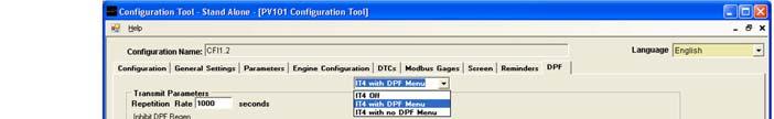
40 DPF NOTE: The new parameter button can be used to add a new parameter for DPF functions. When a parameter is added here, it is also added to the parameter tab. To add a parameter here requires that you be under the 70-parameter limit. Field Description Available choices: IT4 with DPF Menu Adds DPF as a menu item IT4 with no DPF Menu IT4 icons are displayed, but there will be no DPF menu option by default. The DPF menu option can also be enabled/disabled at run-time by using the OEM menu. High Exhaust Temperature Regen Inhibit Restricted Filter For all other fields All parameters listed under the Parameters tab are available for selection. All parameters listed under the Parameters tab are available for selection. All parameters listed under the Parameters tab are available for selection. Place the cursor in the field and view the Help box in the bottom left corner for additional information. NOTE: For information on editing the icons displayed on your PV101-C, see the Image Editor section


41 Text Editor Almost every string in the configuration tool is editable. You know the string is editable when there is an [Edit] button next to the field. It is important to keep in mind when editing strings. All of our default parameters and text strings are translated into multiple languages. When you edit the text string, the translation is no longer valid. You will have to provide your own translations for unique parameter names and text strings

42 Image Editor This editor allows you to edit the images (icons) that are displayed on your PV101-C. You can change the displayed images, add an image from your computer to the image library, delete an image from the library and you can preview how the image will be displayed on the PV101-C screen. There are three tabs under which you can work, Section A: In this area, the currently selected image is displayed. The default images are contained in the library. If you click [Clear], the image will be cleared from the Current Image box. NOTE: While the image is cleared from the Current Image box, it is not removed from the database, nor is it removed as the displayed image on the PV101-C. Section B: In this area, the new image that you have selected is displayed: have selected a new image, it will replace the X.. When you Section C: The action tabs are located in this section. Available Images Tab: Contains the image library from which you can select a new image or delete an image from the library. If you want to select a new image, click on the image. The new image will be displayed in Section B, the New Image window. NOTE: If you do not see the new image in the New Image window, it will not be displayed in the program


43 To delete one or more images from the library, check the box next to the image(s) and click [Delete Selected Images]. Add an Image Tab: from here, you can add an image to the image library. Once the image is added to the library, it can be selected from the Available Images tab. Preview Tab: From here, you can view a mock of how the image will be displayed on the PV101-C screen. It will be displayed in the bottom portion of the screen

44 Reports This module allows you to run a set of pre-defined reports on your configuration settings. You can view, print, or export reports to other formats such as Excel, Word, and PDF files. Use the drop-down list to access all reports. Use the Available Reports include: String Assignment Report provides listing of strings assigned to configuration fields Parameter Report shows all parameters defined for a configuration Configuration Comparison displays the differences between two configurations DTC Listing provides a listing of all DTCs defined in the configuration Text Field Listing provides a listing of all strings used by the configuration. All strings for the default language are listed by their translations. DTC Source Listing lists the address and name of all DTC sources defined in the configuration Parameters String Listing lists the parameter string values mapped to display screens Gage Listing lists all modbus gages defined in the configuration with the description strings for all languages Screen Fields provides a listing of strings assigned to configuration fields Parameter Unit Validation provides a list of units for each measured parameter
![Parameter QA Data Only returns all parameter data as one row per parameter for verification To run a report, click the drop down list and select the desired report, then click [Run Report].](/docs-images/75/72112285/images/45-0.jpg "The report is listed in the pane on the right.")
45 Parameter QA Data Only returns all parameter data as one row per parameter for verification To run a report, click the drop down list and select the desired report, then click [Run Report]. The report is listed in the pane on the right. The icons located across the top of the report allow you to perform the following actions: Export Report Print Report Toggle Group Tree Go to First Page Go to Previous Page Go to Next Page Go to Last Page Go to Page Close Current View Find Text Zoom
46
947-7570 www.murcal.com e-mail: sales@murcal.")
47 CALL MURCAL TO PLACE YOUR ORDER P:(661) F:(661) MurCal
Cascade Configuration Tool
 Cascade Configuration Tool Version 1.0.10 Installation and Operations Manual 00-02-0724 01-25-11 Section 40 In order to consistently bring you the highest quality, full featured products, we reserve the
PowerView Model PV780. Operations Manual Section 78
 PowerView Model PV780 Operations Manual 00-02-0859 2013-03-19 Section 78 In order to consistently bring you the highest quality, full featured products, we reserve the right to change our specifications
PowerView. Model PV-101-A, V2.3 User s Guide Section 78
 PowerView Model PV-101-A, V2.3 User s Guide 10-18-11 00-02-0795 Section 78 In order to consistently bring you the highest quality, full featured products, we reserve the right to change our specifications
PowerView. Model PV-101-C User s Guide Version Catalog Section 78
 PowerView Model PV-101-C User s Guide Version 3.1 10-11-10 00-02-0718 Catalog Section 78 Table of Contents Introduction... 1 Engine and Transmission Parameters 2 Faceplate Features 3 Navigation and Keypad
PowerView TM Model PV350 and PV380. Operations Manual Section 78
 PowerView TM Model PV350 and PV380 Operations Manual 00-02-0879 2012-11-30 Section 78 In order to consistently bring you the highest quality, full featured products, we reserve the right to change our
PowerView. Model PV-101 User s Guide. Rev Catalog Section 78
 PowerView Model PV-101 User s Guide Rev 09-10-08 00-02-0605 Catalog Section 78 In order to consistently bring you the highest quality, full featured products, we reserve the right to change our specifications
TouchKit Touch Panel User manual for WindowsNT4 Version: 3.1.4
 TouchKit Touch Panel User manual for WindowsNT4 Version: 3.1.4 TouchKit Touch Panel v3.1.4 0 CONTENT CHAPTER 1. TOUCH PANEL CONTROLLER... 2 1.1 CONTROLLER... 2 1.2 SPECIFICATIONS AND FEATURES... 3 CHAPTER
PowerView Model PV450. Installation and Operation Manual Section 78
 PowerView Model PV450 Installation and Operation Manual 00-02-0732 05-19-2011 Section 78 In order to consistently bring you the highest quality, full featured products, we reserve the right to change our
HelmView 450 Model HV450. Operation Manual Section 78
 HelmView 450 Model HV450 Operation Manual 00-02-0870 2015-04-16 Section 78 In order to consistently bring you the highest quality, full-featured products, we reserve the right to change our specifications
HelmView Model HV750; Model HVS750. Operations Manual Section 78
 HelmView Model HV750; Model HVS750 Operations Manual 00-02-0805 03-07-12 Section 78 In order to consistently bring you the highest quality, full featured products, we reserve the right to change our specifications
TouchKit Touch Panel User manual for WindowsNT4 Version: 3.1.4
 TouchKit Touch Panel User manual for WindowsNT4 Version: 3.1.4 TouchKit Touch Panel v3.1.4 0 CONTENT CHAPTER 1. TOUCH PANEL CONTROLLER...2 1.1 CONTROLLER...2 1.2 SPECIFICATIONS AND FEATURES...3 CHAPTER
PowerView Model PV750. Installation and Operations Manual Section 78
 PowerView Model PV750 Installation and Operations Manual 00-02-0686 08-20-10 Section 78 In order to consistently bring you the highest quality, full featured products, we reserve the right to change our
HelmView Model HVS780. Operations Manual Section 78
 HelmView Model HVS780 Operations Manual 00-02-0883 2013-02-20 Section 78 In order to consistently bring you the highest quality, full featured products, we reserve the right to change our specifications
For additional information, please consult the Read-Me and Help documentation or contact Electro-Voice or Dynacord technical support.
 Quick Start Guide Hello, and welcome to IRIS-Net software. We want you to get the most from your IRIS-Net projects and encourage you to explore the additional Read-Me and Help documentation provided with
NETWORK PRINT MONITOR User Guide
 NETWORK PRINT MONITOR User Guide Legal Notes Unauthorized reproduction of all or part of this guide is prohibited. The information in this guide is subject to change for improvement without notice. We
Extended Brilliance Workspace v3.5 Report Template Editor
 Extended Brilliance Workspace v3.5 Report Template Editor This is an application guide for Extended Brilliance Workspace v3.5. For more detailed information, please refer to the Philips operator or user
TouchKit TouchScreen Controller User Manual for Windows NT4 Version: 3.4.0
 TouchKit TouchScreen Controller User Manual for Windows NT4 Version: 3.4.0 1 CONTENT CHAPTER 1. TOUCH PANEL CONTROLLER 2 1.1 Controller 2 1.2 Specifications and Features 3 CHAPTER 2. INSTALLING TOUCHKIT
TouchKit Touch Panel User manual for Windows9X/ME Version: 3.1.4
 TouchKit Touch Panel User manual for Windows9X/ME Version: 3.1.4 TouchKit Touch Panel v3.1.4 0 CONTENT CHAPTER 1. TOUCH PANEL CONTROLLER... 2 1.1 CONTROLLER... 2 1.2 SPECIFICATIONS AND FEATURES... 3 CHAPTER
TouchKit TouchScreen Controller User Guide for Windows NT4 Version: 3.2.1
 TouchKit TouchScreen Controller User Guide for Windows NT4 Version: 3.2.1 TouchKit Guide for WinNT4 v3.2.1 0 CONTENT CHAPTER 1. TOUCH PANEL CONTROLLER... 2 1.1 CONTROLLER... 2 1.2 SPECIFICATIONS AND FEATURES...
Centurion C4 Transfer Guide using C4 File Transfer Utility
 1010536 2011-02-23 Section 50 Centurion C4 Transfer Guide using C4 File Transfer Utility 1.0 Background 1.1 A valid configuration is required for the Centurion system. Configuration files are downloaded
#61-844SW ThermalVision Software Instruction Manual
 ThermalVision Software Instruction Manual ND-7035-1 Page 1 of 23 Contents 1. Installing the ThermalVision software onto a PC... 3 2. Transferring saved images from the camera to the PC.... 3 2.1. Direct
Getting Started With the CCPilot VI and QuiC
 Page 1 of 24 Getting Started With the CCPilot VI and QuiC Page 2 of 24 Table of Contents Purpose... 3 What You Will Need... 4 Install the QuiC Tool... 6 Install the QuiC Runtime... 7 Basics of the QuiC
DISCLAIMER Whilst every effort has been made
 PUBLISHED BY Gallagher Group Limited Kahikatea Drive, Private Bag 3026 Hamilton, New Zealand www.gallagherams.com Copyright Gallagher Group Limited 2011. All rights reserved. Patents Pending. MyScale Pro
BASIC NAVIGATION & VIEWS...
 Content Overview VISUAL TOUR... 5 NEW FEATURES IN OUTLOOK 2010... 6 BASIC NAVIGATION & VIEWS... 7 SETTING PREFERENCES... 7 Creating an Outlook Shortcut... 7 Choosing a Startup View... 7 CUSTOMIZING INBOX
KMnet Viewer. User Guide
 KMnet Viewer User Guide Legal Notes Unauthorized reproduction of all or part of this guide is prohibited. The information in this guide is subject to change for improvement without notice. We cannot be
PowerView Model PV450. Installation and Operation Manual Section 78
 PowerView Model PV450 Installation and Operation Manual 00-02-0732 10-19-2011 Section 78 In order to consistently bring you the highest quality, full featured products, we reserve the right to change our
Video recorders Series DH
 Page: 1 DVRs for analog cameras, 960H, HD-SDI Viewclient Program Manual How to install and use the client program to the DVR Page: 2 Contents of this handbook This manual describes how to install and use
Centurion PLUS CPC4 Download Guide using C4 File Transfer Utility
 1010537 2010-03-01 Section 50 Centurion PLUS CPC4 Download Guide using C4 File Transfer Utility 1.0 Background 1.1 The Centurion PLUS Control system consists of a Centurion PLUS Core (CPC4-1) and color
Q-Lab Software OPERATION MANUAL
 Q-Lab Software OPERATION MANUAL Trilithic Company Profile Trilithic is a privately held manufacturer founded in 1986 as an engineering and assembly company that built and designed customer-directed products
KYOCERA Net Viewer 5.3 User Guide
 KYOCERA Net Viewer. User Guide Legal Notes Unauthorized reproduction of all or part of this guide is prohibited. The information in this guide is subject to change without notice. We cannot be held liable
FileMaker. Mobile 2.1. User s Guide. For Windows, Mac, Palm OS, and Pocket PC. Companion for Palm OS and Pocket PC
 For Windows, Mac, Palm OS, and Pocket PC FileMaker Mobile 2.1 Companion for Palm OS and Pocket PC User s Guide 2000-2002 FileMaker, Inc. All Rights Reserved. FileMaker, Inc. 5201 Patrick Henry Drive Santa
Password Memory 7 User s Guide
 C O D E : A E R O T E C H N O L O G I E S Password Memory 7 User s Guide 2007-2018 by code:aero technologies Phone: +1 (321) 285.7447 E-mail: info@codeaero.com Table of Contents How secure is Password
Siemens FINlite User Guide
 Siemens FINlite User Guide Building Technologies User Guide Copyright Notice Copyright Notice Notice Document information is subject to change without notice by Companies, names, and various data used
TouchKit TouchScreen Controller User Guide for Windows 2000 / XP Version: 3.2.4
 TouchKit TouchScreen Controller User Guide for Windows 2000 / XP Version: 3.2.4 TouchKit Guide for Win2000/XP v3.2.4 0 CONTENT CHAPTER 1. TOUCH PANEL CONTROLLER...2 1.1 CONTROLLER...2 1.2 SPECIFICATIONS
CLIQ Web Manager. User Manual. The global leader in door opening solutions V 6.1
 CLIQ Web Manager User Manual V 6.1 The global leader in door opening solutions Program version: 6.1 Document number: ST-003478 Date published: 2016-03-31 Language: en-gb Table of contents 1 Overview...9
Fiery Command WorkStation 5.8 with Fiery Extended Applications 4.4
 Fiery Command WorkStation 5.8 with Fiery Extended Applications 4.4 Fiery Extended Applications (FEA) v4.4 contains Fiery software for performing tasks using a Fiery Server. This document describes how
Navigator Software User s Manual. User Manual. Navigator Software. Monarch Instrument Rev 0.98 May Page 1 of 17
 User Manual Navigator Software Monarch Instrument Rev 0.98 May 2006 Page 1 of 17 Contents 1. NAVIGATOR SOFTWARE 2. INSTALLATION 3. USING NAVIGATOR SOFTWARE 3.1 STARTING THE PROGRAM 3.2 SYSTEM SET UP 3.3
1) Installing Bluetooth software for Windows (A) Place installation CD into PC and setup should launch automatically.
 Installing Bluetooth software for Windows (A) Place installation CD into PC and setup should launch automatically.") 1) Installing Bluetooth software for Windows (A) Place installation CD into PC and setup should launch automatically. If setup does not launch, use Windows Explorer to navigate to the appropriate CD- ROM
1) Installing Bluetooth software for Windows (A) Place installation CD into PC and setup should launch automatically. If setup does not launch, use Windows Explorer to navigate to the appropriate CD- ROM
3. IMPORTANT: When prompted, accept the default Installation directory.
 Installing ProView 4.0.1 on your PC 1. Insert the ProView 4.0.1 CD-ROM into your CD-ROM Drive. The Install Shield Wizard should run automatically. If it does not, click Start then Run. Enter D:\setup.exe
PowerView Model PV450. Installation and Operation Manual Section 78
 PowerView Model PV450 Installation and Operation Manual 00-02-0732 2016-02-26 Section 78 In order to consistently bring you the highest quality, full featured products, we reserve the right to change our
RedBeam Inventory Tracking User Manual
 RedBeam Inventory Tracking User Manual Contact us at www.redbeam.com. Page 1 Table of Contents Table of Contents... 2 Overview... 4 RedBeam Inventory Tracking... 4 PC Prerequisites... 4 Mobile Computer
1.4 MConfig PC software can be optionally used to upload/download configuration settings to the VRU Pro using RS-485 communication.
 FW Murphy VRU Pro Configuration Guide using MConfig v1.60 February 18, 2016 1.0 General Information 1.1 All VRU Pro controllers have firmware that controls the operation of the controller. The latest version
Microsoft Windows 10. Quick Reference. Watsonia Publishing 47 Greenaway Street Bulleen VIC 3105 Australia
 Watsonia Publishing 47 Greenaway Street Bulleen VIC 3105 Australia www.watsoniapublishing.com info@watsoniapublishing.com Quick Reference Course Code: INF1440 Table of Contents Chapter 1: Starting With
GO! Finder V1.4. User Manual
 GO! Finder V1.4 User Manual 1 Tables of Contents GO! Finder Introduction-------------------------------------------------------------------------------------1 System Requirements ---------------------------------------------------------------------------------------2
vbound User Guide vbound User Guide Version Revised: 10/10/2017
 vbound User Guide Version 4.1.1 Revised: 10/10/2017 Copyright 2014-2017 FFL Solutions Inc. Page 1 of 87 Table of Contents Using vbound...5 Starting vbound... 5 Bound Book List... 6 vbound Ribbon Menu...
SMART Recorder. Record. Pause. Stop
 SMART Recorder The recorder is used to record actions that are done on the interactive screen. If a microphone is attached to the computer, narration can be recorded. After the recording has been created,
Legal Notes. Regarding Trademarks KYOCERA MITA Corporation
 Legal Notes Unauthorized reproduction of all or part of this guide is prohibited. The information in this guide is subject to change without notice. We cannot be held liable for any problems arising from
FileMaker. Mobile 7. User s Guide. For Windows, Mac, Palm OS, and Pocket PC. Companion for Palm OS and Pocket PC
 For Windows, Mac, Palm OS, and Pocket PC FileMaker Mobile 7 Companion for Palm OS and Pocket PC User s Guide 2000-2004 FileMaker, Inc. All Rights Reserved. FileMaker, Inc. 5201 Patrick Henry Drive Santa
HVR LINE INSTALL GUIDE
 HVR LINE INSTALL GUIDE 4.9.07 HVR v2.4.1 455 E. Industrial Drive P.O. Box 94 Hartland, WI 53029 Technical Support: 262.369.8798 Sales & Service: 262.369.8797 efax: 312.602.1356 www.visioncontrols.net Basic
PowerView PV380-R2 Murphy Standard Configuration
 2016-06-15 00-02-0997 Section 78 PowerView PV380-R2 Murphy Standard Configuration Operations Manual *Products covered in this document comply with European Council electromagnetic compatibility directive
JPRO Fleet Service Portal User s Guide
 JPRO Fleet Service Portal User s Guide 1 System Requirements Supported Operating Systems Windows 2000 Windows XP Hardware Requirements Minimum: 128 MB RAM, 2 GB HD, Pentium II, 1024 x 768 monitor Recommended:
KYOCERA Net Viewer User Guide Supplement
 KYOCERA Net Viewer User Guide Supplement Legal Notes Unauthorized reproduction of all or part of this guide is prohibited. The information in this guide is subject to change without notice. We cannot be
GSC400 Series. GSC400 Programmer and PC Interface User Manual
 GSC400 Series GSC400 Programmer and PC Interface User Manual GSC400 Programmer and PC Interface User Manual Full Version File: GSC400 PC Interface Rev1.2.doc, August 2009 2 of 33 Amendments Issue Section
Secure Guard Central Management System
 Speco Technologies, Inc. Secure Guard Central Management System Usage Information Contents 1 Overview... 7 2 Installation... 7 2.1 System Requirements... 7 2.2 System Installation... 7 2.3 Command Line
DBT-120 Bluetooth USB Adapter
 DBT-120 Bluetooth USB Adapter Rev.2.1 (09/25/2002) 2 Contents Introduction... 5 Package Contents... 6 Installing Bluetooth Software... 6 Hardware Installation... 8 Introduction to Bluetooth Software...
Exhibitor Software User s Manual. Exhibitor Software V
 Exhibitor Software User s Manual Exhibitor Software V1.0.1 090908 1 Contents 1. Exhibitor Software 2. Installation 3. Using Exhibitor Program 3.1 Starting the Program 3.2 Logging in to the Program 3.3
GSC400 Series. GSC400 Programmer and PC Interface User Manual
 GSC400 Series GSC400 Programmer and PC Interface User Manual GSC400 Programmer and PC Interface User Manual Full Version File: GSC400 PC Interface Rev1.5.doc, December 2010 2 of 42 Thank You For Purchasing
Installation Guide Command WorkStation 5.6 with Fiery Extended Applications 4.2
 Installation Guide Command WorkStation 5.6 with Fiery Extended Applications 4.2 Fiery Extended Applications Package (FEA) v4.2 contains Fiery applications for performing tasks associated with a Fiery Server.
Workshare Compare 9.5
 Workshare Compare 9.5 User Guide Workshare 9.5.3 April 2018 9.5.787.3184 Workshare Compare 9.5 User Guide Table of Contents Chapter 1: Introducing Workshare Compare...8 What is Workshare Compare?... 9
Working with PDF s. To open a recent file on the Start screen, double click on the file name.
 Working with PDF s Acrobat DC Start Screen (Home Tab) When Acrobat opens, the Acrobat Start screen (Home Tab) populates displaying a list of recently opened files. The search feature on the top of the
User Manual. MPPTracker. Management Software for Solar Charge Controller. Version: 1.2
 User Manual MPPTracker Management Software for Solar Charge Controller Version: 1.2 Table of Contents 1. MPPTracker Overview... 1 1.1. Introduction... 1 1.2. Features... 1 2. MPPTracker Install and Uninstall...
OTC 3210 Update Instructions
 OTC 3210 Update Instructions Date of Release: June 2016 New Software ID: ACAC Previous Software ID: D4A8 or 6D2B Note: Scanning Suite should already be installed on the PC. Verify Scan Tool Software Version
MCDOUGAL LITTELL EASYPLANNER USER S GUIDE
 MCDOUGAL LITTELL EASYPLANNER USER S GUIDE 1 Introduction The McDougal Littell EasyPlanner allows you to quickly and easily access Resource materials such as tests, quizzes, books, and other supporting
DATA LOGGING SOFTWARE FOR 4-WAY BALL VALVE DIGITAL MANIFOLD
 DATA LOGGING SOFTWARE FOR 4-WAY BALL VALVE DIGITAL MANIFOLD The Mastercool Data Logger Application provides all the necessary Recorder and Display Functions to record, display and save new data or playback
Microsoft Access 2013
 Microsoft Access 2013 Chapter 1 Databases and Database Objects: An Introduction Objectives Describe the features of the Access window Create a database Create tables in Datasheet and Design views Add records
SolarPower Pro. User s Manual. Management Software for Solar Inverter
 SolarPower Pro User s Manual Management Software for Solar Inverter Table of Contents 1. SolarPower Pro Overview... 2 1.1. Introduction... 2 1.2. Structure... 2 1.3. Features... 3 2. SolarPower Pro Install
DriveWizard Plus Instruction Manual
 DriveWizard Plus Instruction Manual To properly use the product, read this manual thoroughly. MANUAL NO. TOEP C730600 20C Table of Contents Safety Symbols and Markings...4 Manual Overview...5 Related Manuals...5
Calendar & Buttons Dashboard Menu Features My Profile My Favorites Watch List Adding a New Request...
 remitview User Guide 1 TABLE OF CONTENTS INTRODUCTION... 3 Calendar & Buttons... 3 GETTING STARTED.... 5 Dashboard.... 7 Menu Features... 8 PROFILE.... 10 My Profile... 10 My Favorites... 12 Watch List...
Backup Recording Viewer for NS
 Backup Recording Viewer for NS Installation and Operation Manual Version 1.0 Poltys, Inc. 3300 N. Main Street, Suite D, Anderson, SC 29621-4128 +1 864 642 6103, sales@poltys.com www.poltys.com 2013 Poltys,
User Guide. Web Intelligence Rich Client. Business Objects 4.1
 User Guide Web Intelligence Rich Client Business Objects 4.1 2 P a g e Web Intelligence 4.1 User Guide Web Intelligence 4.1 User Guide Contents Getting Started in Web Intelligence 4.1... 5 Log into EDDIE...
User Addendum User Box Scan support on the Fiery E C-KM Color Server, version 1.1
 User Addendum User Box Scan support on the Fiery E 10 50-45C-KM Color Server, version 1.1 This document describes installing software for User Box scan support on the Fiery E 10 50-45C-KM Color Server,
Océ Account Center. User manual
 Océ Account Center User manual Océ-Technologies B.V. Copyright 2004, Océ-Technologies B.V. Venlo, The Netherlands All rights reserved. No part of this work may be reproduced, copied, adapted, or transmitted
Aurora Multi-image System Control Software. User Manual
 Aurora Multi-image System Control Software User Manual Product Information Model: Aurora Controller Software Version: V010200 Release Date: January 18th, 2017 Company OSEE TECHNOLOGY CO., LTD. Contact
User's Guide. For CarChip and CarChip E/X 8210 & 8220
 User's Guide TM For CarChip and CarChip E/X 8210 & 8220 Product Number: 8210, 8220 Davis Instruments Part Number: 7395.064 DriveRight CarChip User s Manual Rev A (January 2, 2003) Davis Instruments Corp.,
QUICK START. DevCom2000 User Manual
 QUICK START DevCom2000 uses Device Descriptions (DDs) to access data stored in the memory of the smart field device. These DDs are developed by the manufacturer for their products and, in turn, distributed
Table of Contents.
 Table of Contents http://www.advancedactuators.com 1. Items Included with the ThumbLock PCMU:... 2 2. IMPORTANT NOTE:... 2 3. Supported Operating Systems:... 2 Section 1 Installing the ThumbLock PCMU Software...
User Manual. Thermo Scientific Orion
 User Manual Thermo Scientific Orion Orion Star Com Software Program 68X637901 Revision A April 2013 Contents Chapter 1... 4 Introduction... 4 Star Com Functions... 5 Chapter 2... 6 Software Installation
- Contents - - Hard-disk space 280MB of available hard-disk space
 ------ ScanSnap Manager V4.0L20 README File PFU LIMITED ------ - Contents - 1. System requirements 2. Cautions Regarding USB and Your Computer 3. Cautions for Windows Vista Users 4. Cautions Concerning
KYOCERA Net Viewer User Guide
 KYOCERA Net Viewer User Guide Legal Notes Unauthorized reproduction of all or part of this guide is prohibited. The information in this guide is subject to change without notice. We cannot be held liable
Spectrometer Visible Light Spectrometer V4.4
 Visible Light Spectrometer V4.4 Table of Contents Package Contents...3 Trademarks...4 Manual Driver and Application installation...5 Manual Application Installation...6 First Start of the Application...8
Introduction to Personal Computers Using Windows 10 and Microsoft Office 2016
 Watsonia Publishing 47 Greenaway Street Bulleen VIC 3105 Australia www.watsoniapublishing.com info@watsoniapublishing.com Introduction to Personal Computers Using Windows 10 and Microsoft Office 2016 Quick
Electrical System Functional Definition
 Electrical System Functional Definition Preface What's New? Getting Started Basic Tasks Advanced Tasks Workbench Description Customizing Glossary Index Dassault Systèmes 1994-2000. All rights reserved.
TouchScreen Controller User Manual
 TouchScreen Controller User Manual for Windows 9X / ME Version: 3.4.0 Customer : Model : 32-4W232/4WUSB/5W232/5WUSB-BB Date : Version: Acceptance Sheet Onetouch Technologies Co., Ltd. (Supplier) (Purchaser)
Telephony Toolbar Enterprise. User Guide
 Telephony Toolbar Enterprise User Guide Release 4.4 October 2009 Table of Contents 1 Summary of Changes... 7 1.1 Changes for this Release... 7 2 About This Guide... 8 2.1 Open Telephony Toolbar-Corporate...
PowerScheduler Course Tally Worksheet instructions.
 PowerScheduler Course Tally Worksheet instructions. This document will describe the process of copying course request information from PowerSchool into an Excel Course Tally Worksheet. Once the information
AKCess Pro Server Access Control User Manual
 www.akcp.com AKCess Pro Server Access Control User Manual Help Version updated till version 118 Copyright 2012, AKCess Pro Co., Ltd.. 1) Introduction A) What is the AKCess Pro Server / Access Control?
FX Tools Software Package - FX CommPro N2 User s Guide
 User s Guide FX CommPro N2 Issue Date September 25, 2008 FX Tools Software Package - FX CommPro N2 User s Guide FX Tools Software Package FX CommPro N2... 3 Introduction...3 Installation... 4 Installing
How to View Cases and Customize the Homepage in Customer Service Central Cisco and/or its affiliates. All rights reserved. 1
 How to View Cases and Customize the Homepage in Customer Service Central 1 This module will show you how to view cases and customize the homepage in Customer Service Central. Please note that in My Cisco,
Sun VirtualBox Installation Tutorial
 Sun VirtualBox Installation Tutorial Installing Linux Mint 5 LTS Guest OS By Dennis Berry Welcome to the world of virtualization and Linux. This tutorial is intended to help users who are new to the world
PACS ADMIN. Quick Reference Guide
 Quick Reference Guide PACS ADMIN Creating Domain Users.......................................................... Adding NOVARAD Users......................................................... Adding Console
Release Date: September 4, 2014
 MV1DU User s Guide Release Date: September 4, 2014 Use of the MV1DU Diagnostic System requires an active license agreement or MV-1 Dealer Agreement. For information on obtaining a license, please email
Adobe Sign for MS Dynamics 365 CRM
 Adobe Sign for MS Dynamics 365 CRM User Guide v7 Last Updated: May 31, 2018 2018 Adobe Systems Incorporated. All rights reserved Contents Overview... 3 Gaining Access to Adobe Sign...4 Sending for Signature...
User Guide 701P Wide Format Solution Wide Format Scan Service
 User Guide 701P44865 6204 Wide Format Solution Wide Format Scan Service Xerox Corporation Global Knowledge & Language Services 800 Phillips Road Bldg. 845-17S Webster, NY 14580 Copyright 2006 Xerox Corporation.
Windows 7. More Skills 11 Manage Fonts. To complete this project, you will need the following file: You will save your file as: CHAPTER 7
 M07_TOWN5764_01_SE_SM7.QXD 11/17/10 11:55 AM Page 1 CHAPTER 7 Windows 7 More Skills 11 Manage Fonts A font is a design applied to a collection of letters, numbers, and symbols. Each font is assigned a
PowerView - Model PV101 V2.2 Fuel Sender Calibration
 1010585 09-30-10 Section 78 PowerView - Model PV101 V2.2 Fuel Sender Calibration Setting Fuel Level Analog Input Introduction This option enables the operator to configure the PV101 to accept the optional
IGSS Configuration Workshop - Exercises
 IGSS Configuration Workshop - Contents Exercise 1: Working as an Operator in IGSS... 2 Exercise 2: Creating a New IGSS Project... 18 Exercise 3: Create Areas and Diagrams in Definition... 23 Exercise 4:
Temperature-Humidity Sensor Configuration Tool Rev. A 1/25/
 Rev. A 1/25/213 172 Contents Contents Temperature-Humidity Sensor Configuration Tool... 3 Read Sensor Screen... 3 Manual Calibration Screen... 4 Register View Screen... 5 Modbus Registers... 6 Reprogram
Updating the operating system and BONGO (MCU) firmware
 firmware") RELEASE NOTES Trimble Juno T41, Juno 5, Slate Controller, and Spectra Precision T41 Series: Windows Embedded Handheld (WEH) 6.5 Operating System Release Notes and Update Instructions These release notes
RELEASE NOTES Trimble Juno T41, Juno 5, Slate Controller, and Spectra Precision T41 Series: Windows Embedded Handheld (WEH) 6.5 Operating System Release Notes and Update Instructions These release notes
Guide to User Interface 4.3
 Datatel Colleague Guide to User Interface 4.3 Release 18 June 24, 2011 For corrections and clarifications to this manual, see AnswerNet page 1926.37. Guide to User Interface 4.3 All Rights Reserved The
ThinkVantage Fingerprint Software
 ThinkVantage Fingerprint Software 12 2 1First Edition (February 2006) Copyright Lenovo 2006. Portions Copyright International Business Machines Corporation 2006. All rights reserved. U.S. GOVERNMENT