EX8. User Manual. Ver 1.0
|
|
|
- Merry Lambert
- 5 years ago
- Views:
Transcription


1 EX8 User Manual Ver 1.0

2 EX8 manual ver1.0 Power supply important issue! Use separate power supply when ever is possible, one for EX8 and Reader and another for door lock. This way electrical isolation between lock and EX8 protect the EX8 from any electrical noise generated by lock or damages caused by improper or damaged cabling of the lock. Single power supply for EX8 and lock can be used if it has been made for this purpose. If single power supply is to be used it must be tested by installer along with door lock before installation. ll locks do not have same electrical characteristics so the test must be done with lock that will be mounted at user site. Keep power supply unit as close as possible to EX8. If longer distances are unavoidable, use screened cables for 12V supply line. Product concept The EX8 is used in a combination with fingerprint reader making standalone biometric access system. Fig.1 Typical application 2

3 Mounting EX8 Controller Housing 43 Readers Recommended position ioxr 3

4 ioc ioin 4


5 Wiring EX8 overview Terminals side Front side Terminal side Terminal Description 12V DC Power supply, +12V GND Gnd_P P D1 D0 Gnd 12Vout Tamp Tamp NC 2 Com 2 NO 2 NC 1 Com 1 NO 1 Item F1 J1 Front side L1 L2 L3 Power supply, 0V Exit button Exit button Reader input RS485 Reader input RS485 Reader input D1 Reader input D0 Reader supply, 0V Reader supply, 12V Tamper out Tamper out Relay 2, Normally closed terminal Relay 2, common Relay 2, Normally open terminal Relay 1, Normally closed terminal Relay 1, common Relay 1, Normally open terminal Description Fuse 1 Master PIN reset jumper Red LED linking Error ON Reader not found Green LED ON Relay 1 activated Orange red ON Relay 2 activated 5
6 Connections Readers EX8 + ioxr EX8 + ioc Terminal Terminal Name 12Vout 1 +12V Gnd 2 0V D0 5 D0 D1 6 D1 7 8 Terminal Wire color Name 12Vout Red +12V Gnd lack GND D0 White D0 D1 Yellow D1 Pink Violet EX8 + ioin Terminal Terminal Name 12Vout 8 +12V Gnd 7 GND D0 3 D0/D D1 4 D1/CL 1 2 Connecting reader with Cat5 network cable example rown +12V rown/white D1 lue 0V lue/white D0 Orange Orange/White Green Tamper Green/White Tamper Maximum cable length 6
7 Door control Power supply type Door strike (fail safe) Electromagnetic lock (fail open) DC C Exit button 7
8 Programming Master PIN reset Turn OFF the power supply Close jumper J1 Turn ON the power supply. Yellow LED will blink and buzzer will sound. Open jumper J1 Master password is reset to default 000 Change master PIN code (change Master PIN XXX to YYY) Input ction LED status 0 Enter submenu 0 (Enroll user) 000 Enter user number 000 YYY Enter new password (YYY) To change master PIN from 000 to 123: Enroll a User (User number ZZZ, Finger F) Input ction LED status XXX Enter master password XXX 0 Enter submenu 0 (Enroll user) ZZZ Select user number ( ) 1 Select finger 1 Present the finger 1 on the reader Enroll Wait for OK beep Enroll done 2 Select finger 2 Present the finger 2 on the reader Enroll Wait for OK beep Enroll done ack to menu 0 ack to main menu To enroll User 001 (with Master PIN = 000): present finger + wait for OK beep wait for OK beep Set user PIN (User number ZZZ, PIN PPPPP) Input ction LED status 0 Enter submenu 0 (Enroll user) ZZZ Select user number ( ) 3 Select user PIN menu PPPPP Enter user PIN (must be 5 digits ) ack to menu 0 ack to main menu To assign PIN to User 123(with Master PIN = 000):
9 Set Relay1 open time Input ction LED status 1 Enter submenu 1 (Relay 1 time) TT Enter open time TT 0 = toggle mode 1-99 = timed, 1-99 seconds To set Relay1 open time to 3 seconds (with Master PIN = 000): Set Relay2 open time Input ction LED status 2 Enter submenu 2 (Relay2 time) TT Enter open time TT 0 = toggle mode 1-99 = timed, 1-99 seconds To set Relay2 open time to 3 seconds (with Master PIN = 000): Delete user Input ction LED status 9 Enter submenu 9 (Delete user) ZZZ Enter user number ZZZ ( ) To delete User 123 (with Master PIN = 000): Delete all users Input ction LED status 8 Enter submenu 8 (Delete all users) 999 Enter delete all command To delete all users (with Master PIN = 000):
10 ssign relays to a User Input ction LED status 3 Enter submenu 3 (ssign relays) ZZZ Enter user number R Enter output combination R: 0 = Disable user (User is not deleted) 1 = Relay1 only 2 = Relay2 only 3 = Relay1 and Relay2 To assign Relay1 to User 123 (with Master PIN = 000): Fingerprint sensor sensitivity setup Input ction LED status 7 Enter submenu 7 (Sensor setup) 1 Enter sensitivity setup menu S Enter sensitivity S (0-7, 7 = most sensitive) To set sensor to most sensitive (with Master PIN = 000): Fingerprint sensor security setup Input ction LED status 7 Enter submenu 7 (Sensor setup) 2 Enter security setup menu S Enter security level: 1 = normal 2 = secure 3 = more secure To set sensor to normal security level (with Master PIN = 000):
11 Programming flowchart Enter Master PIN + (default: ) Validation OK? Yes Short + Long beep (OK eep) Main Menu No Three small beeps (Error eep) + RED Led blinks Enroll User 0 Change Master PIN 0 Relay 1 Time 1 Relay 2 Time 2 ssign Relays 3 Sensor Settings 7 Delete ll Users 8 Delete User 9 Enter User Number Press seconds or 00 ON/OFF Mode (Latch mode) Enter User Number Sensitivity 1 Security 2 Press 999 Enter User Number Enroll Enroll Enter Finger 1 Finger 2 PIN (5digits) Enter NEW PIN (1 to 8 digits) 1 for Out1 OR 2 for Out2 OR 12 for both OR 0 for neither 0 to 7 0 least sensitive to 7 most sensitive 1 normal 2 secure 3 more secure Orange LED on iometry Reader is blinking. Green LED on EX8 is blinking. Orange LED on iometry Reader is blinking. Orange LED on EX8 is blinking. Present finger on the reader Press to validate Press to validate Wait for 3 sec and OK beep from EX8 Validation OK? No Three beeps (Error eep) ack one level (see semaphore) Yes Short + Long beep (OK eep) To exit the menu Press until the three LED s are OFF 11


12 Enrollment Enrollment area Correct enrollment Incorrect enrollment Troubleshooting Symptom Problem Solution EX8 and reader not operating at all. On powering the system, at the EX8, red LED stays ON while yellow LED blinks every 30 seconds Reader authorize the finger but door do not open ad fingerprint reading EX8 reset when door lock is activated No power supply No communication between EX8 and reader If green LED at EX8 is ON (Relay1 is activated) it is lock problem If green LED at EX8 is OFF (Relay1 is not activated) it is EX8 problem Dirty or damaged sensor Finger too dry User have too smooth fingerprints Finger is damaged ad power supply - Check main C power - Power supply unit - Replace fuse F1 - Check cable, terminals and - Replace reader - Replace EX8 - Check lock power supply - Check lock - ssign relays to user Check D0 and D1 connections Clean the sensor (do not use abrasive cleaning solutions) Touch your forehead - Increase sensor sensitivity - Decrease security level Enroll other finger Replace power supply unit or use separate supply for lock Safety precautions Do not install the device in a place subject to direct sun light without protective cover. Do not install the device and cabling close to a source of strong electro-magnetic fields like radio-transmitting antenna. Do not place the device near or above heating equipments. If cleaning, do not spray or splash water or other cleaning liquids but wipe it out with smooth cloth or towel. Do not let children touch the device without supervision. Note that if the sensor is cleaned by detergent, benzene or thinner, surface is damaged and fingerprint can t be entered. 12
13 Technical specification EX8 + ioxr EX8 + ioc EX8 + ioin Fingerprint sensor Capacitive uthentication Finger or PIN Finger Finger 999 Users, 2 Users capacity templates per user, 1 PIN code per user 999 Users, 2 templates per user Reader dimensions (HxWxD in mm) 132 x 86 x x 50 x x 90 x 53 Reader weight (g) Reader protection class IP65 IP54 IP54 Indoor use Indoor use Indoor use Power supply 12V DC (11 14 V DC) Relay outputs 2 Exit button 1 Current consumption 250m max. (without door lock) Recommended Temperature Range 0-40 o C Extended temperature range Storage temperature Humidity Tamper protection Reader lockout o C Human contact with sensor at extreme temperatures not recommended o C 85% non-condensing Yes, all readers and EX8 30sec lockout after 16 invalid fingers or PIN codes Models may vary. 13
 Name Finger 1 ( J) Finger 2 ( J) PIN (00000-99999) Relays")
14 Recommended fingers are,, E, F, G, J Do not write in this page, make copy. Users register User ( ) Name Finger 1 ( J) Finger 2 ( J) PIN ( ) Relays 1, 2 or 1&2 14
CV-945 Stand-Alone Biometric Reader. Installation Instructions
 CV-945 Stand-Alone Biometric Reader Installation Instructions Contents 1.0 Introduction... 03 2.0 Mounting... 03 3.0 Specifications... 04 4.0 Application Diagram... 04 5.0 Wiring... 05 6.0 Recommended
BIOC3 V1 USER S MANUAL. Biometric Reader v. b1
 BIOC3 V1 EN Biometric Reader USER S MANUAL v. b1 www.xprgroup.com 1 Contents 1. DESCRIPTION 2. SPECIFICATIONS 3. MOUNTING 4. WIRING 5. CONNECTING BIOMETRIC READERS TO EWS CONTROLLER 5.1 CONNECTING BIOMETRIC
B100-SA Standalone Biometric Reader
 EN B100-SA Standalone Biometric Reader User Manual v.b1 Contents 1.0 INTRODUCTION 2.0 MOUNTING 3.0 SPECIFICATIONS......... 3 3 3 4.0 APPLICATION DIAGRAM... 4 5.0 WIRING... 4 6.0 RECOMMENDED SWIPING TECHNIQUE...
DINB100-SA Standalone Biometric Reader
 a Visual Plus Corporation Company EN DINB100-SA Standalone Biometric Reader User Manual v.a1 Contents 1.0 INTRODUCTION... 2.0 MOUNTING AND DISMOUNTING... 3.0 SPECIFICATIONS... 4.0 APPLICATION DIAGRAM 5.0
DINB100-SA Standalone Biometric Reader
 EN DINB100-SA Standalone Biometric Reader User Manual v.b2 Contents 1.0 INTRODUCTION... 3 2.0 MOUNTING AND DISMOUNTING... 3 3.0 SPECIFICATIONS... 3 4.0 APPLICATION DIAGRAM... 4 5.0 WIRING... 4 6.0 RECOMMENDED
B100PROX-MF-SA Standalone Biometric Mifare Reader USER S MANUAL. Relay1 time (for Relay 1 in B100PROX-MF-SA,RU2, RTT and DINRTT )
") 11.9 Set Door Relay Time Relay1 time (for Relay 1 in B100PROX-MF-SA,RU2, RTT and DINRTT ) Relay2 time (for Relay 2 in RU2, DINRTT Remote Relay Unit) B100PROX-MF-SA Standalone Biometric Mifare Reader Swipe
11.9 Set Door Relay Time Relay1 time (for Relay 1 in B100PROX-MF-SA,RU2, RTT and DINRTT ) Relay2 time (for Relay 2 in RU2, DINRTT Remote Relay Unit) B100PROX-MF-SA Standalone Biometric Mifare Reader Swipe
DINB100-SA-KIT Standalone Biometric Kit
 DINB100-SA DINRTT DINB100-SA-KIT Standalone Biometric Kit User Manual v.b3 Contents 1.0 INTRODUCTION... 3 2.0 MOUNTING AND DISMOUNTING... 3 3.0 SPECIFICATIONS... 3 4.0 APPLICATION DIAGRAM... 4 5.0 WIRING...
DINBIOC3 V1 USER S MANUAL. EN Biometric Reader. v.b2
 DINBIOC3 V1 EN Biometric Reader USER S MNUL v.b2 1 Contents 1. DESCRIPTION 2. SPECIFICTIONS 3. MOUNTING 4. WIRING 4.1 CONNECTING DINBIOC3 V1 WITH DINMTPX PROXIMITY REDER 4.2 CONNECTING DINBIOC3 V1 WITH
QUICK START GUIDE. 2.4 Inch TFT Terminal Time Attendance & Access Control
 QUICK START GUIDE 2.4 Inch TFT Terminal Time Attendance & Access Control Safety Precautions The following precautions are to keep user safe and prevent any damage. Please read carefully before installation.
Contents Safety precautions Product components Optional accessories Names of each parts Product Dimension Cables and Connectors Power Connection
 Contents Safety precautions Product components Optional accessories Names of each parts Product Dimension Cables and Connectors Power Connection LAN Connection RS485 Connection Relay Connection Digital
CM-110SK Standalone Keypad Installation Instructions
 CM-0SK Standalone Keypad Installation Instructions. Packing List Qty Name Remarks 2 2 Keypad User manual Screwdriver Wall plugs Self-tapping screws Torx screw 0.8 x 2.4 Φ(20 mm 60 mm) 0.24 x.2 Φ (6 mm
Waterproof. Keypad/Reader/Controller
 Waterproof Keypad/Reader/Controller User Manual W1-C W3-C User manual 1. Packing List Name Quantity Remarks Digital Keypad-W1-C/W3-C 1 User manual 1 Screw driver 1 Rubber bungs 4 6*27mm, used for fixing
Safety Precautions How to place the finger Product Contents Product PIN Diagram Product Dimensions Cables and Connectors Installation of Back Plate
 www.zkaccess.com Safety Precautions How to place the finger Product Contents Product PIN Diagram Product Dimensions Cables and Connectors Installation of Back Plate Power Connection Ethernet Connection
INSTALLATION GUIDE 2.4 Inch TFT Terminal Time Attendance & Access Control
 STALLATION GUIDE.4 Inch TFT Terminal Time Attendance & Access Control Optional accessories Safety Precautions The following precautions are to keep user s safe and prevent any damage. Please read carefully
CV-110SPK Standalone Keypad/Prox Access Control Installation Instructions
 CV-110SPK Standalone Keypad/Prox Access Control Installation Instructions 1. Packing List Qty Name Remarks 1 1 1 2 2 1 Keypad User manual Screwdriver Wall plugs Self-tapping screws Torx screw 0.8 x 2.4
F6-Fingerprint. Access Control/Reader. User Manual. F6 - Simplified Instruction. (Master Code) # (Factory default:1234) Enter the Programming Mode
 # (Factory default:1234) Enter the Programming Mode") -Fingerprint Access Control/Reader Function Description Enter the Programming Mode - Simplified Instruction Operation (Factory default:1234) Change the Master Code Add Fingerprint User Add Card User Add
-Fingerprint Access Control/Reader Function Description Enter the Programming Mode - Simplified Instruction Operation (Factory default:1234) Change the Master Code Add Fingerprint User Add Card User Add
BIOPAD-M V1. Biometric keypad reader INSTALLER MANUAL. v.b2
 BIOPD-M V1 EN Biometric keypad reader INSTLLER MNUL v.b2 1 Contents 1. DESCRIPTION 2. SPECIFICTIONS 3. MOUNTING 4. WIRING 5. CONNECTING BIOMETRIC REDERS TO EWS CONTROLLER 5.1 CONNECTING BIOMETRIC REDERS
Fingerprint Access Control F1. User Manual
 Fingerprint Access Control F1 User Manual 1. Introduction F1 is a metal shell standalone fingerprint access control, using the America Atmel s MCU, with precise electron circuit and good productive technology.
Installation Guide (ver 1.0)
") IP based Fingerprint Access Control Installation Guide (ver 1.0) www.supremainc.com Contents Safety precautions 3 Basics of fingerprint recognition 5 How to place a finger 6 Product Contents 8 Front Side
IP based Fingerprint Access Control Installation Guide (ver 1.0) www.supremainc.com Contents Safety precautions 3 Basics of fingerprint recognition 5 How to place a finger 6 Product Contents 8 Front Side
BIOPAD-M Biometric Keypad Reader User s Manual
 BIOPD-M Biometric Keypad Reader User s Manual v.a4 EN Contents 1. DESCRIPTION 2. SPECIFICTIONS 3. MOUNTING 4. WIRING 5. CONNECTING BIOMETRIC REDERS TO EWS CONTROLLER 5.1 CONNECTING BIOMETRIC REDERS IN
Quick Start Guide. ProBio & ProFAC + ZKBioSecurity 3.0
 Quick Start Guide ProBio & ProFAC + ZKBioSecurity 3.0 CONTENT 1 Safety Precautions...2 On Using Face Recognition Device...3 Device Overview...5 Product Dimensions & Installation...6 Power Connection...7
Wiring Guide. EP.NMiNi 2. Version 1.04 Last Updated:
 Wiring Guide EP.NMiNi 2 Version 1.04 Last Updated: 31-01-2013 Before you begin Technical Support If you cannot find the answer to your question in this manual or in the Help files, we recommend you contact
BIOPROX-MF V1 Biometric Mifare Reader
 This product herewith complies with requirements of EMC directive 2014/30/EU. In addition it complies with RoHS directive EN50581:2012 BIOPROX-MF V1 Biometric Mifare Reader User s Manual Visual Plus Corporation,
AS Keypad User Manual
 AS Keypad User Manual Specifications Operating Voltage: 12~24 VAC/DC Current Draw: TBA Input: request-to-exit (for Relay 1) time out reed switch contact (for Relay 1) Output: Relay 1: N.O./N.C./Com. Output
Single Door Standalone Access Control User Manual
 Single Door Standalone Access Control User Manual Reading this manual carefully before install and use the device 1. Packing List Name Quantity Remarks Keypad User manual Screw driver Rubber plug Self
CM-500 SK 500 USER CODES KEYPAD
 CM-500 SK 500 USER CODES KEYPAD Wiring diagram PCB front view ST2 1 3 1 3 N/C contact RL1 (magnet) N/O contact RL1 (strike) ST1 3 2 1 ST2 1 3 RL2 RL1 Strike 2 1 E M B 3 5 T C O 12 V V1 PB2 PB1 Input voltage
Installation Guide (ver 1.0)
") IP based Fingerprint Access Control Installation Guide (ver 1.0) www.supremainc.com Contents Safety precautions 3 Basics of fingerprint recognition 5 How to place a finger 6 Product Contents 8 Front Side
IP based Fingerprint Access Control Installation Guide (ver 1.0) www.supremainc.com Contents Safety precautions 3 Basics of fingerprint recognition 5 How to place a finger 6 Product Contents 8 Front Side
Digital Keypad Introduction
 K2 Digital Keypad Introduction The K02 uses the latest microprocessor technology to operate door strikes and security systems that require a momentary (timed) or latching dry contact closure. All programming
EL-ST100 KEYPAD CONTROLLER
 WIRING DIAGRAM EL-ST100 KEYPAD CONTROLLER WEATHER-PROOF STANDALONE ACCESS CONTROLLER WITH KEYPAD & PROXIMITY TECHNOLOGY Programming and Installation Manual NOTE: www.elock2u.com ICT at work! Version 3.6
Standalone Keypad Access Control. User Manual. Please read the manual carefully before use this unit
 Standalone Keypad Access Control User Manual Please read the manual carefully before use this unit 1. Packing List Name Quantity Remarks Keypad 1 User manual 1 Screw driver 1 Φ20mm 60mm,Special for keypad
Standalone Keypad Access Control. User Manual. SS-TS2000 Size:120*80*25 mm
 Standalone Keypad Access Control User Manual SS-TS2000 Size:120*80*25 mm Please read the manual carefully before use this unit 1. Packing List Name Quantity Remarks Keypad 1 User manual 1 Screw driver
DG-800 Stand-Alone Proximity Reader Instruction Manual
 DG-800 Stand-Alone Proximity Reader Instruction Manual I. Features 1. Memory volume up to 1000+10 proximity cards/tokens and PINs with the programming time up to 0.5 seconds. 2. Access modes: a. Only Proximity
REX F-0-9 Standalone or Access Controller
 REX F-0-9 Standalone or Access Controller Power supply The controller need s external power supply to operate. The Spider W40 power supply is sufficient to power two controllers and two 12V electric strikes
W3-H Waterproof Keypad/Reader/Controller
 W3-H Waterproof Keypad/Reader/Controller User Manual 1. Packing list Name Quantity Digital Keypad W3-H 1 User Manual 1 Screw Driver Rubber Bungs Self Tapping Screws Diode 1 4 4 1 Manager Card 2 Remark
RFT1000 reader in RACS 5. User Manual
 Roger Access Control System RFT1000 reader in RACS 5 User Manual Firmware version: 1.3 or newer Hardware version: 1.1 Document version: Rev. A 2016 ROGER sp. z o.o. sp.k. All rights reserved. This document
IP based Fingerprint Access Control. Installation Guide.
 IP based Fingerprint Access Control Installation Guide EN 101.00.BEP (ver V1.30 1.2) www.supremainc.com Contents Safety precautions 3 Basics of fingerprint recognition 5 How to place a finger 6 Product
1. Product Specification
 1. Product Specification Item Specification Voltage 12VDC +10%, Current 1.2A Lock Relay 12VDC/2A Environmental Temperature working:0 ~45 ; storage:-10 ~55 Relative humidity working:40%~90%rh; Card Capacity
DOLXFD1000B. Waterproof Access Control/Reader
 DOLXFD1000B Waterproof Access Control/Reader INTRODUCTION The DOLXFD1000B is a single- entry multi-function Access Controller with integrated keypad and card reader. It is designed and manufactured to
INSTALLATION GUIDE. InBio Pro Series Access Control Panels. Date: June, 2016 Version: 1.3
 INSTALLATION GUIDE InBio Pro Series Access Control Panels Date: June, 2016 Version: 1.3 2 What s in the Box 2 Screws & Anchors 2 Screwdriver 4 Diode CONTENT Contents What s in the Box...2 Optional accessories...4
B100PROX-EH(AH) Biometric Proximity Reader INSTALLER MANUAL
 Biometric Proximity Reader INSTALLER MANUAL") B100PROX-EH(H) EN Biometric Proximity Reader INSTLLER MNUL 1 CONTENTS 1. DESCRIPTION 2. SPECIFICTIONS 3. MOUNTING 4. WIRING 5. CONNECTING BIOMETRIC REDERS TO EWS CONTROLLER 5.1 CONNECTING BIOMETRIC REDERS
B100PROX-EH(H) EN Biometric Proximity Reader INSTLLER MNUL 1 CONTENTS 1. DESCRIPTION 2. SPECIFICTIONS 3. MOUNTING 4. WIRING 5. CONNECTING BIOMETRIC REDERS TO EWS CONTROLLER 5.1 CONNECTING BIOMETRIC REDERS
TEC100 USER/INSTALLER MANUAL V2.0 REV. 03/2018
 TEC100 USER/INSTALLER MANUAL V2.0 REV. 03/2018 00. CONTT 01. SAFETY INSTRUCTIONS INDEX 01. SAFETY INSTRUCTIONS STANDARDS TO FOLLOW 02. PRODUCT PRODUCT PROFILE TECHNICAL PARAMETERS 03. INSTALLATION PRODUCT
VANDAL RESISTANT BACK-LIT WEATHERPROOF ACCESS CONTROL KEYPAD
 VANDAL RESISTANT BACK-LIT WEATHERPROOF ACCESS CONTROL KEYPAD Post Mount Keypad Programming & Installation Manual 1. Connect Power 12V DC to 24V AC/DC to terminals (+) and (-) Post Mount Keypad Quick Start
INSTALLATION GUIDE BioLite Net English Version 2.10 EN BLN V2.10A
 www.supremainc.com INSTALLATION GUIDE English Version 2.10 EN 101.00.BLN V2.10A Contents Safety Instructions... 3 Getting Started... 5 Components... 5 Part names and features... 6 Cables and connectors...
User Manual. Before using this device, read and follow all instructions for safety
 User Manual Before using this device, read and follow all instructions for safety Copyrightc 2014 KJTECH Co., Ltd. All rights reserved. It is provided for informational purposes only in this manual. All
SL2000E. Status Output. Electronic Code Lock. Features. Input. Exit Button Input. Introduction. Door Contact Input. Functional Description.
 SL2000E Electronic Code Lock Features Door Relay output Status transistor output Aux transistor output Door Contact input Exit Button input INSTALLER code for programming MASTER code for arming/disarming
Manual er under oversettelse til norsk.
 Manual er under oversettelse til norsk. Suprema Inc. 16F Parkview Office Tower, Jeongja-dong, Bundang-gu, Seongnam, Gyeonggi, 463-863 Korea E-mail : support@supremainc.com Website : www.supremainc.com
INSTALLATION INSTRUCTIONS 920 EntryCheck TM
 801 Avenida Acaso, Camarillo, Ca. 93012 (805) 494-0622 www.sdcsecurity.com E-mail: service@sdcsecurity.com INSTALLATION INSTRUCTIONS 920 EntryCheck TM The EntryCheck 920 Indoor/Outdoor Keypad is a surface-mount
INSTALLATION GUIDE BioEntry Plus English Version 2.11 EN BEP V2.11A
 www.supremainc.com INSTALLATION GUIDE English Version 2.11 EN 101.00.BEP V2.11A Contents Safety Instructions... 3 Getting Started... 4 Components... 4 Features... 5 Part names and features... 5 Cables
BioEntry W. Installation Guide. Compact Outdoor Fingerprint Reader/Controller EN BEW V1.20.
 Compact Outdoor Fingerprint Reader/Controller Installation Guide EN 101.00.BEW V1.20 www.supremainc.com Important Safety Information Carefully review the information within the user manual before installing/operating
VIS-3200 / VIS-3201 User Manual
 2.4GHz Indoor Black Wireless Exit Button Receiver Keypad / Reader Access Control 500 Users Range of 50 Feet Delay and On/Off Toggle Mode Battery Operated Standalone No Software 1 VIS-3200 / VIS-3201 User
Partizan PAB-FC2. Fingerprint scan time Fingerprint identification time. <0.5 s < % <0.0198% Ingress protection rating
 1. Features & Technical Parameters 1.1 Features: Partizan PAB-FC2 Metal vandalproof housing Secure and reliable biometric fingerprint recognition Simple for using, wiring can be done by a user without
CV-550SPK V2 Waterproof Keypad/Reader/Controller Installation Instructions
 CV-550SPK V2 Waterproof Keypad/Reader/Controller Installation Instructions Packing List NAME MODEL/SIZE QTY Self tapping screw 0.15 x 1.06 (4mm 27 mm) Rubber plug 0.23 x 1.2 (6mm 30 mm) Star screw driver
EcoEntry. RFID Proximity Access Control System. User Guide. Revision 2
 EcoEntry RFID Proximity Access Control System User Guide Revision 2 Introduction The ecoentry door access system allows the user to open the door using a keyfob, password, or keyfob plus password. Specification
W3-M. Metal waterproof standalone access control/reader. User Manual
 W3M Metal waterproof standalone access control/reader User Manual Name Digital Keypad W3M User Manual Screw driver Rubber bungs Selftapping screws Diode 1. Packing List Quantity 1 1 1 4 4 1 Remark 6*27mm,
Instruction Manual. Vogue. Security. Technology. Innovation 2013-V01
 Instruction Manual DH16A-60DTE Model 60 with plastic keypad, stand alone access control DH16A-60DTQE Model 60 with plastic keypad, networked access control 2013-V01 Security Technology Vogue Innovation
User Manual. PCKeypad Wireless Keypad
 User Manual PCKeypad Wireless Keypad Description The PCKeypad is a wireless keypad with a PentaCODE transmitter built-in. It works with all of Elsema s PCR series receivers. The installer has the option
INSTALLATION INSTRUCTIONS 920P EntryCheck TM
 801 Avenida Acaso, Camarillo, Ca. 93012 (805) 494-0622 www.sdcsecurity.com E-mail: service@sdcsecurity.com INSTALLATION INSTRUCTIONS 920P EntryCheck TM The EntryCheck 920P Indoor/Outdoor Keypad is a surface-mount
Biometric Lock Programming & Operating Instructions. info. code. Biometric Lock Information. Setting The Master Code. Enrolling A Fingerprint
 Biometric Lock Programming & Operating Instructions? info Biometric Lock Information code Setting The Master Code fingerprint Enrolling A Fingerprint Backlight Backlight Settings changing battery Changing
INSTALLATION GUIDE BioEntry W English Version 2.10 EN BEW V2.10A
 www.supremainc.com INSTALLATION GUIDE English Version 2.10 EN 101.00.BEW V2.10A Contents Safety Instructions... 3 Getting Started... 4 Components... 4 Features... 5 Part names and features... 5 Cables
RD-SR2 ACCESS SECURITY PRODUCTS LTD. Proximity Card Reader with Remote Control. User Manual
 RD-SR2 Proximity Card Reader with Remote Control User Manual INTRODUCTION The RD-SR2 is a compact, weather resistant multi-function card reader that can be used as a standalone programmable access control
INSTALLATION INSTRUCTIONS Model 930 EntryCheck
 SECURITY DOOR CONTROLS 3580 Willow Lane, Westlake Village, CA 91361-4921 (805) 494-0622 Fax: (805) 494-8861 www.sdcsecurity.com E-mail: service@sdcsecurity.com INSTALLATION INSTRUCTIONS Model 930 EntryCheck
INSTALLATION INSTRUCTIONS 921P EntryCheck TM
 80 Avenida Acaso, Camarillo, Ca. 90 (805) 494-06 www.sdcsecurity.com E-mail: service@sdcsecurity.com INSTALLATION INSTRUCTIONS 9P EntryCheck TM The EntryCheck 9P Indoor/Outdoor Keypad is a surface mount
Contents Installation Instructions 3 Installation Diagrams System Overview Wiring Diagrams Network Diagrams
 Contents Installation Instructions Installation Diagrams System Overview Wiring Diagrams Network Diagrams Operating Instructions Fingerprint Enrollment 3 4 6 8 9 12 19 Wi-Plus Controller www.transmittersolutionssmart.com
Operation manual For NG BIOSINGLE Version 1.1
 Operation manual For NG BIOSINGLE Version 1.1 SMART-I ELECTRONICS SYSTEMS PVT. LTD.(An ISO 9001:2008 certified company) R&D, Training & Customer Support Center: First Floor, Arihant Plaza Phase II, Village-Ovala,
VIDI-AC-2CS Access Controller/ Reader
 VIDI-AC-2CS Access Controller/ Reader User Manual CONTENTS INTRODUCTION 2 INSTALLATION.4 STANDALONE MODE 6 CONTROLLER MODE.11 WIEGAND READER MODE.. 13 ADVANCE APPLICATION..14 1 INTRODUCTION The VIDI-AC-2CS
RBR-SB-KTZ001 LAR 2. User Manual
 RBR-SB-KTZ001 LAR 2 User Manual INTRODUCTION KTZ001 is a compact, waterproof stand-alone programmable access control system that provides proximity entry for up to 2000 users. Read both EM and HID card.
Stand-alone Proximity Access Control
 Stand-alone Proximity Access Control User Manual INTRODUCTION VIDI-AC-1C is a compact, waterproof stand-alone programmable access control system that provides proximity entry for up to 2000 users. It uses
INSTALLATION GUIDE BioEntry W2 English Version 1.00 EN BEW2 V1.00A
 www.supremainc.com INSTALLATION GUIDE English Version 1.00 EN 101.00.BEW2 V1.00A Contents Safety Instructions... 3 Introduction... 5 Components... 5 Name and function of each part... 6 Cables and connectors...
User Manual. Split access control with intelligent secured power supply.
 User Manual Split access control with intelligent secured power supply. Contents. Introduction, features and specifications. Installation and Wiring Diagram 3. Manager Card Operation 4. User Settings 5.
Finger Vein Access Control device Quick Start Guide Version: 1.0 Date: June USB slot. USB slot
 Overview Fingerprint & Finger Vein Device Front Left Side: Finger Vein Device Touch screen Card reader Fingerprint reader Finger vein reader Finger vein sensor: During registration, after finger touches
UNIVERSAL EXPANDER FOR CARD / CHIP READERS INT-R. 1. Features. 2. Installation and start-up
 UNIVERSAL EXPANDER FOR CARD / CHIP READERS INT-R int-r_en 09/11 The INT-R expander interfaces with the INTEGRA and CA-64 alarm control panels, replacing the previously offered CA-64 SR and CA-64 DR expanders.
Comfort, the Intelligent Home System. Comfort Fingerprint Reader Interface FPR01
 Comfort, the Intelligent Home System Comfort Fingerprint Reader Interface FPR01 Introduction to the Comfort Fingerprint Reader Interface... 1 Specifications... 2 Equipment... 2 Settings... 2 Connections...
Portals 14 What is a portal? 14 Hardware 15 RS232 to RS USB to RS TCP/IP to RS Add a Serial Portal 16 Add a Network portal 16
 PROS LITE User Manual Version 2.0.0 www.visual-plus.com Table of Contents Getting Started 5 Starting PROS Lite 5 Create a Portal 5 Adding a control panel 6 Adding a user 7 Upload users to a controller
Wiring Guide EP.NMINI. Version 1.02 Last Updated:
 Wiring Guide EP.NMINI Version 1.02 Last Updated: 14-10-2014 1 Note: See http://www.entrypass.net/ for updates, revisions, and download the latest installation manual There are currently 2 version of EntryPass
Xpass S2. Installation Guide. Intelligent IP Access Control Reader EN XPS2 V1.11.
 Intelligent IP Access Control Reader Installation Guide EN 101.00.XPS2 V1.11 www.supremainc.com Important Safety Information Carefully review the information within the user manual before installing or
Fingerprint Identification Proximity Reader. Quick Installation Guide
 Fingerprint Identification Proximity Reader Quick Installation Guide 1. WHAT S INCLUDED Please unpack and check the contents of the box. If any of these parts are missing, please contact a nearby distributor
MODEL KP-100 ACCESS CONTROL DIGITAL KEYPAD OPERATING INSTRUCTIONS
 MODEL KP-100 ACCESS CONTROL DIGITAL KEYPAD OPERATING INSTRUCTIONS Model KP-100 is a self-contained digital keypad. This keypad is suitable for residential, industrial, and commercial installations. It
BHD-8000 Access Control Keypad and Card Reader. Wiring Diagram
 BHD-8000 Access Control Keypad and Card Reader Wiring Diagram Frontal View Main Technical Specifications Item Operating Voltage Unlock Relay Operating Temperature Value 12VDC+12%/1.2A 12VDC/2A Normal Operation:
4 Wire Video Intercom System
 VT596(F)/KP USER MANUAL(EN) 4 Wire Video Intercom System VT596/KP VT596F/KP Read this manual carefully before using the product, and keep it well for future use. -1-1. Parts and Functions Camera Lens Speaker
-DTZ001- Stand-Alone Proximity Access Control. User Manual
 -DTZ001- Stand-Alone Proximity Access Control User Manual INTRODUCTION DTZ001 is a compact, waterproof stand-alone programmable access control system that provides proximity entry for up to 2000 users,
GENERAL QUICK START GUIDE
 GENERAL QUICK START GUIDE 2.8InchPalm & Fingerprint Time Attendance & Access Terminal Version: 1.0 Date: May., 2017 Note: The picture and function presented in this manual are only for reference. The following
FTK5 PROXIMITY KEYPAD
 FTK5 PROXIMITY KEYPAD Before using the unit, please read the instructions and retain for future reference 1 There are 600 user codes (fobs or cards) and 1 programming code: Careful administration records
RXTH DUAL ROOM SENSOR / SWITCH
 DUAL ROOM SENSOR / SWITCH FOR TEMPERATURE AND RELATIVE HUMIDITY Mounting and operating instructions Table of contents SAFETY AND PRECAUTIONS 3 PRODUCT DESCRIPTION 4 ARTICLE CODES 4 INTENDED AREA OF USE
INSTALLATION GUIDE BioStation L2 English Version 1.00 EN BSL2 V1.00A
 www.supremainc.com INSTALLATION GUIDE English Version 1.00 EN 101.00.BSL2 V1.00A Contents Safety instructions... 3 Introduction... 5 Components... 5 Name and function of each part... 6 Cables and connectors...
Wireless Digital Video Doorbell
 Wireless Digital Video Doorbell User s Manual Door Camera Indoor Handset Remark Please follow the user manual for correct installation and testing, if there is any doubt, please call our tech-supporting
Synergis Master Controller 2.2 Integration Guide for Axis Interface Modules
 Synergis Master Controller 2.2 Integration Guide for Axis Interface Modules This guide supplements the Synergis Master Controller Configuration Guide and explains how to configure Axis interface modules
EZ-TAG2 Manual_Layout 5 11/12/ :14 Page 1 U S E R M A N UAL
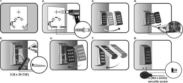
 EZ-TAG2 Manual_Layout 5 11/12/2012 09:14 Page 1 USER MANUAL EZ-TAG2 Manual_Layout 5 11/12/2012 09:14 Page 2 Contents EZ-TAG2 and Back Plate 1 x Security Torx Key 4 x Screws and raw plugs 1 x Marking out
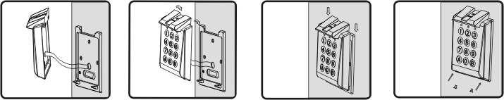
RТTH DUAL ROOM SWITCH
 DUAL ROOM SWITCH FOR TEMPERATURE AND RELATIVE HUMIDITY Mounting and operating instructions Table of contents SAFETY AND PRECAUTIONS PRODUCT DESCRIPTION ARTICLE CODES INTENDED AREA OF USE TECHNICAL DATA
GV-AS Controller. Installation Guide
 GV-AS Controller Installation Guide Before attempting to connect or operate this product, please read these instructions carefully and save this manual for future use. 2011 GeoVision, Inc. All rights reserved.
INSTALLATION GUIDE BioStation 2 English Version 1.3 EN BS2 V1.30A
 www.supremainc.com INSTALLATION GUIDE English Version 1.3 EN 101.00.BS2 V1.30A Contents Safety Instructions... 3 Getting Started... 5 Components... 5 Parts... 6 Cables and Connectors... 8 How to Enroll
RXTP ROOM TEMPERATURE
 ROOM TEMPERATURE CONTROLLER WITH PI CONTROL Mounting and operating instructions Table of contents SAFETY AND PRECAUTIONS 3 PRODUCT DESCRIPTION 4 ARTICLE CODES 4 INTENDED AREA OF USE 4 TECHNICAL DATA 4
Two Door Controller GEN-045
 Australian Owned, Designed and Manufactured Two Door Controller GEN-045 Genesis Electronics Australia Pty Ltd www.genesiselectronics.com.au Distributed by: Genesis reserves the right to change or modify
F18. Fingerprint capacity 3,000 Transaction capacity 100,000 Hardware Platform ZK 6001, 400Mhz 64M Flash, 32MSDRAM. Identification speed
 F18 Features: 1. 2.4 TFT LCD color screen 2. Standard Wiegand Input and Output interfaces are compatible with most all 3 rd party 26 bit Wiegand readers and access control panels. 3. USB HOST port makes
RTT2 ROOM TEMPERATURE SWITCH. Mounting and operating instructions
 Mounting and operating instructions Table of contents SAFETY AND PRECAUTIONS PRODUCT DESCRIPTION ARTICLE CODES INTENDED AREA OF USE TECHNICAL DATA STANDARDS OPERATIONAL DIAGRAMS WIRING AND CONNECTIONS
RFID/Digital Access Control Keypad
 R Luminous/ RFID/Digital Access Control Keypad Model:YK-368L-R Germany EMC tested FEATURES AND FUNCTIONS Simple Programming, Easy Operation 3-Operation Mode: ID Card Operation, User Code Operation, ID
Keypad CT2000. Art. No.: , (black) Art. No.: , (white) Installation Manual
 Art. No.: , (white) Installation Manual") secure open Keypad CT Art. No.:, (black) Art. No.:, (white) Installation Manual CT_installation_ENGmay Conlan ApS Speditorvej A DK- Aalborg Tel: + Fax: + www.conlan.eu info@conlan.eu Table of contents.
secure open Keypad CT Art. No.:, (black) Art. No.:, (white) Installation Manual CT_installation_ENGmay Conlan ApS Speditorvej A DK- Aalborg Tel: + Fax: + www.conlan.eu info@conlan.eu Table of contents.
721EX Access Controller Installation
 721EX Access Controller Installation 721EX Controller Standalone Controller Specifications Max Card Capacity: 3000 What is included in the box B-Id 721EX controller board RS485/Serial converter USB/Serial
SF200. Installation Guide & Quick Start Guide. 2 TFT AC Terminal Version: 1.0 Date: June 2014
 SF200 Installation Guide & Quick Start Guide 2 TFT AC Terminal Version: 1.0 Date: June 2014 All design and specification declared are subject to change without notice in advance. Contents Safety Precautions
Biometric finger print entry system.
 Biometric finger print entry system. Installation / Operating Instructions. v1.0b ML-E-BIO-KIT (non-bluetooth) ML-E-BTBIO-KIT (Bluetooth Enabled) Table of Contents Introduction.... 3 Installation & Operating
SeaViewer Cameras, Inc. DVR-SD. SD Digital Video Recorder. User s Manual
 SeaViewer Cameras, Inc. DVR-SD SD Digital Video Recorder User s Manual Please read this User s Manual carefully to ensure that you can use the device correctly and safely. The contents of this manual are