Packet Tracer: Novice Session 2007 Cisco Systems, Inc. All rights reserved. Cisco Public. Packet Tracer: Novice Session
|
|
|
- Willa Dean
- 6 years ago
- Views:
Transcription
1 Packet Tracer: Novice Session Packet Tracer: Novice Session 1
2 How Can I Use Packet Tracer? Problem Scenario: Your students need to learn how to configure a router Ethernet interface and to verify connectivity to this interface from a PC that has been configured to participate on the network. How can you demonstrate this to the whole group? How can they practice what they ve learned? How can you test their ability to complete all of the steps on their own? Use Packet Tracer! Novice Session 2
3 The Topology As a group: Start with the finished topology. Walk students through the steps. Individually: Students will create the devices, connect the devices, and configure the devices. Students will test connectivity from the PC to the router. Novice Session 3
4 Skills Demonstrated in this Session Create and arrange devices Create connections Configure devices Verify connectivity Simulation mode Novice Session 4
5 Creating and Devices Arranging Connecting Devices Devices Novice Session 5

6 Create the Devices To create a device: 4. Click on the workspace. 1. Click the Select tool, if necessary. 2. Choose a device type. 3. Choose a device. Novice Session 6
7 Common Tools The Common Tools bar includes: Select tool for selecting Move tool for moving the entire topology Note tool for adding notes anywhere on the topology Delete tool for removing devices and links Resize tool for changing the size of devices in Physical View Novice Session 7

8 Some Tips A Few Tips: You can create multiple instances of the same device by holding down the CTRL key and drag the device. Cancel creating a device by clicking on it again or another tool. Also, the ESC key will cancel any action. Multiple devices can be selected at one time using the select tool and dragging a box around the desired devices. Novice Session 8
9 PT 5.2 Features Device Template Copy ZoomIn Undo ZoomOut Manager Cluster Move function function Paste ZoomReset Palette Novice Session 9


10 Legacy Devices (PT5.x) Novice Session 10
 The new")

11 New Devices (PT5.x) The new device: laptop-pt Novice Session 11

")

 Novice Session")
12 Multiuser Cloud and New Laptop PTMP TCP/IP The Multiuser connection (Peer0 in the picture) can connect by TCP/IP to a Multiuser connection of another PT (Instance on a different computer) Novice Session 12
13 Devices Connecting Devices Novice Session 13
14 Smart Connection To connect devices: 4. Click on the first device. 5. Click on the second device. 1. Click the Select tool, if necessary. 2. Choose the Connection icon. 3. Choose the Smart Connection icon. Novice Session 14


15 Port Status Red indicates that the link is down. Remember that the default state of a router interface is shutdown. Novice Session 15
16 Viewing Port Labels Mouse over the connection to see which ports Packet Tracer selected when making the Smart Connection. Novice Session 16


17 Port Label Options and Other Options Novice Session 17
18 Configuring Devices Novice Session 18
19 GUI Configuration In this example, we are assuming that students either have not learned configuration through CLI, or are just beginning to learn this. Packet Tracer offers students the ability to make some basic configuration changes through a GUI interface, while also showing them the equivalent IOS commands. Novice Session 19


20 Configuring Router Hostname 2. Type hostname in both places; one for Display Name and one for Hostname 3. Device name is updated in topology. 1. To configure a device, click on it and then click the Config tab. 4. Equivalent IOS commands are shown here. Novice Session 20


21 Configure Router FastEthernet Interface 1. Click on an interface to configure it. 3. Activate the Interface. 4. IOS Commands are updated and the link light is now green. 2. Enter the IP Address and Subnet Mask. Novice Session 21


22 Configure the PC Gateway Click on a PC and then click on the Config tab to configure it. Under GLOBAL Settings, you can change the PC Name and enter the gateway IP Address. Novice Session 22


23 Configure the PC IP Address Click on FastEthernet under INTERFACE to configure the IP Address and Subnet Mask. Novice Session 23


24 Add Notes Click on Note tool button to add notes to the topology. Novice Session 24


25 Network Description Click on I icon to add a Network Description. Novice Session 25


26 Save Your Configurations and File Save your file by selecting File Save Save your router configs by clicking the NVRAM Save button. Novice Session 26
27 Verify Connectivity Novice Session 27
28 Verifying Connectivity There are several ways to verify connectivity in Packet Tracer. In Realtime mode, open a command prompt from the PC desktop and issue a ping just as you would in the classroom with real equipment. In Simulation Mode, create a simulation that allows you to open up the packet at different points along the path to view how the device is processing the packet. Novice Session 28


29 Verifying in Realtime Mode In Realtime mode, select Desktop from the tabbed interface. Click the Command Prompt icon to open a command prompt from the PC. Novice Session 29


30 Ping the Gateway Issue a ping to the Gateway. Novice Session 30
31 Run a Devices Connecting Simulation Devices Novice Session 31


32 Simulation Mode Switch to Simulation Mode. Novice Session 32
33 Simulation Mode? Most of the work so far has been completed in the Realtime Mode. In Realtime Mode, your network is always running (like a real network) whether you are working on the network or not. Your configurations are created and modified in real time, and the network responds in real time. Simulation Mode is used to observe network traffic in a detailed and controlled pace to observe the paths that packets take and inspect packets in detail. Simulation Mode allows us to create and examine packets. Novice Session 33

34 Create a PDU 3. Select the Destination Device. 1. Click the Simple PDU icon. 2. Select the Source device. Novice Session 34
35 Event List The Event List window records (or "captures") what happens as your PDU propagates the network. The Event List can be filtered to show specific kinds of traffic. The PDU List will show the PDU information. Novice Session 35

36 Playing the Simulation Click the Auto Capture/Play button to begin the simulation. Novice Session 36

37 Results As the simulation runs, events will be added to the list. These events show the packet s state at each step along the path. A successful ping will show a green check mark. Novice Session 37
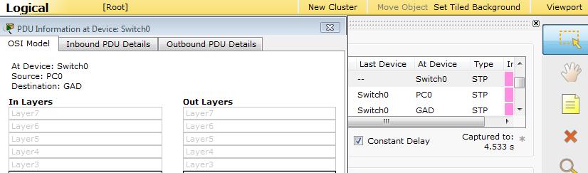

38 PDU Information Novice Session 38
39 Novice Session 39
Packet Tracer: Novice Session. Packet Tracer: Novice Session 2007 Cisco Systems, Inc. All rights reserved. Cisco Public
 Packet Tracer: Novice Session Packet Tracer: Novice Session 1 How Can I Use Packet Tracer? Problem Scenario: Your students need to learn how to configure a router Ethernet interface and to verify connectivity
Department Of Computer Science
 Department Of Computer Science Laboratory Manual Prepared By: Muhammad Nouman Farooq Lecturer and Course Coordinator Course: Computer Communication and Networks (CS-205) Page 1 of 43 Table of Contents
Packet Tracer Create a Simple Network Using Packet Tracer
 Using Packet Tracer Topology Addressing Table Device Interface IP Address Subnet Mask Default Gateway PC Ethernet0 DHCP 192.168.0.1 Wireless Router Cisco.com Server LAN 192.168.0.1 255.255.255.0 Internet
Antonio Cianfrani. Packet Tracer
 Antonio Cianfrani Packet Tracer Packet Tracer (1/2) Packet Tracer? Cisco Packet Tracer is a software able to emulate CISCO networking devices. Packet Tracer features: Allows to create network topologies
Internetworking with Packet Tracer
 Internetworking with Packet Tracer Objectives Develop an understanding of the basic functions of Packet Tracer. Create/model two simple Ethernet networks connected by a switch. Observe traffic behavior
Using Packet Tracer to Build a Network
 Using Packet Tracer to Build a Network We will be using Packet Tracer today to create the following network. This topology requires one 2811 router two 2960 switches and three workstations. Launch Packet
GAME100 Lab 5. Before beginning the lab, please download and install Cisco Packet Trace
 GAME100 Lab 5 Name: Part 1: Learn to Use Packet Tracer Objectives Develop an understanding of the basic functions of Packet Tracer. Create/model a simple Ethernet network using two hosts and a switch.
NETWORK LAB 2 Configuring Switch Desktop
 Configuring Switch 1. Select the switch tab and then add a switch from the list of switches we have to the workspace, we will choose (2950-24) switch. 2. Add a number of PCs next to the switch in order
Experiment 3: Protocol Visualization with Packet Tracer
 Experiment 3: Protocol Visualization with Packet Tracer Learning Objectives: Explore Packet Tracer Real-time mode Explore the Logical Workspace Explore Packet Tracer operation Connect devices Examine a
NET323 D: NETWORKS PROTOCOLS
 1 NET323 D: NETWORKS PROTOCOLS Networks and Communication Systems Department TA. Anfal AlHazzaa Lab # 2 : Hub Vs. Switch Lab Objectives 2 To create two small LANs contain three PCs using Packet Tracer
Configuration and management of Networks LAB 1 Introduction to packet tracer
 LAB 1 Introduction to packet tracer Objectives: Learn Packet Tracer to design and simulate networks. Learn to create a simple LAN with two PCs using an Ethernet hub and two straight through cables to connect
Classful Address Subnet Mask Number of Hosts per Subnet (2 x 2)
") LAB 1 Exercise 1- Subnetting exercises. Write the subnet, broadcast address, and valid host range for question 1 through question 6: 1. 192.168.100.25/30 2. 192.168.100.37/28 3. 192.168.100.66/27 4. 192.168.100.17/29
LAB 1 Exercise 1- Subnetting exercises. Write the subnet, broadcast address, and valid host range for question 1 through question 6: 1. 192.168.100.25/30 2. 192.168.100.37/28 3. 192.168.100.66/27 4. 192.168.100.17/29
Packet Tracer - Explore a Network
 Topology Objectives Part 1: Examine Internetwork Traffic at Branch Part 2: Examine Internetwork Traffic to Central Part 3: Examine Internet Traffic from Branch Background This simulation activity is intended
on the bottom left hand corner you will find all the devices you need.
 Create a simple LAN in packet tracer Things you will need 1) Generic PC 1) Switch 1) Server open packet tracer on the bottom left hand corner you will find all the devices you need. Click on END DEVICES
Packet Tracer Mini-Lab 04: Supplement Configuring 2 LANs and 2 Routers with Config in Packet Tracer
 Packet Tracer Mini-Lab 04: Supplement Configuring 2 LANs and 2 Routers with Config in Packet Tracer CAVEAT: THE LABS IN CC2-180 MAY NOT WORK ENTIRELY AS PLANNED. WE WILL BE UTILIZING BOTH A SERVER 2012
CNPE Communications and Networks Lab Book: Data Transmission Over Digital Networks
 Lab Book: Data Transmission Over Digital Networks Contents Data Transmission Over Digital Networks... 3 Lab Objectives... 3 Lab Resources... 3 Task 1 Build the Home Network... 3 Task 2 Configure IP Addresses...
Use of the TCP/IP Protocols and the OSI Model in Packet Tracer
 Communication Networks [Netw501] Spring 2018 Tutorial 3 Packet Tracer Activity 3 Use of the TCP/IP Protocols and the OSI Model in Packet Tracer Introduction: In Packet Tracer simulation mode, detailed
Introduction to the Packet Tracer Interface using a Hub Topology
 Introduction to Packet Tracer What is Packet Tracer? Packet Tracer is a protocol simulator developed by Dennis Frezzo and his team at Cisco Systems. Packet Tracer (PT) is a powerful and dynamic tool that
This document is exclusive property of Cisco Systems, Inc. Permission is granted to print and copy this document for non-commercial distribution and
 This document is exclusive property of Cisco Systems, Inc. Permission is granted to print and copy this document for non-commercial distribution and exclusive use by instructors in the CCNA Exploration:
NET323 D: NETWORKS PROTOCOLS
 1 NET323 D: NETWORKS PROTOCOLS Networks and Communication Systems Department TA. Anfal AlHazzaa Lab # 6 : Dynamic Route (OSPF Single area) Lab Objectives 2 To connect small LANs using routers. To configure
NET323 D: NETWORKS PROTOCOLS
 1 NET323 D: NETWORKS PROTOCOLS Networks and Communication Systems Department TA. Anfal AlHazzaa Lab # 5 : Dynamic Route (RIP) Lab Objectives 2 To connect small LANs using routers. To configure dynamic
Lab#01 - Introduction to Packet Tracer
 Lab#01 - Introduction to Packet Tracer What is Packet Tracer? Packet Tracer is a protocol simulator developed by Dennis Frezzo and his team at Cisco Systems. Packet Tracer (PT) is a powerful and dynamic
Lab 1. CLI Navigation. Scenario. Initial Configuration for R1
 Lab 1 CLI Navigation This lab covers the most basic skills for accessing and using the command-line interface (CLI) on a Cisco router or switch. Many of the small, picky details of how the CLI works cannot
Network II Lab 01. Part 01: Interface Overview. Program interface
 Part 01: Interface Overview Network II Lab 01 This initial interface contains ten components. If you are unsure of what a particular interface item does, move your mouse over the item and a help balloon
Packet Tracer Mini-Lab 08: Supplement Configuring 2 LANs/2 Routers using Config, CLI, & RIPv2
 Packet Tracer Mini-Lab 08: Supplement Configuring 2 LANs/2 Routers using Config, CLI, & RIPv2 CAVEAT: THE LABS IN CC2-180 MAY NOT WORK ENTIRELY AS PLANNED. WE WILL BE UTILIZING BOTH A SERVER 2012 R2 HOST
CNBK Communications and Networks Lab Book: Purpose of Hardware and Protocols Associated with Networking Computer Systems
 Lab Book: Purpose of Hardware and Protocols Associated with Networking Computer Systems Contents Purpose of Hardware and Protocols Associated with Computer Networks... 3 Lab Objectives... 3 Lab Resources...
Lab : Challenge OSPF Configuration Lab. Topology Diagram. Addressing Table. Default Gateway. Device Interface IP Address Subnet Mask
 Topology Diagram Addressing Table Device Interface IP Address Subnet Mask Default Gateway Fa0/0 HQ S0/0/0 S0/0/1 Lo1 10.10.10.1 255.255.255.252 Fa0/0 Branch1 S0/0/0 S0/0/1 Fa0/0 Branch2 S0/0/0 S0/0/1 PC1
PT Activity: Configuring a Zone-Based Policy Firewall (ZPF)
") PT Activity: Configuring a Zone-Based Policy Firewall (ZPF) Instructor Version Topology Diagram Addressing Table Device Interface IP Address Subnet Mask Default Gateway R1 R2 R3 Fa0/1 192.168.1.1 255.255.255.0
PT Activity: Configuring a Zone-Based Policy Firewall (ZPF) Instructor Version Topology Diagram Addressing Table Device Interface IP Address Subnet Mask Default Gateway R1 R2 R3 Fa0/1 192.168.1.1 255.255.255.0
Packet Tracer - Investigating the TCP/IP and OSI Models in Action (Instructor Version Optional Packet Tracer)
") (Instructor Version Optional Packet Tracer) Instructor Note: Red font color or gray highlights indicate text that appears in the instructor copy only. Optional activities are designed to enhance understanding
(Instructor Version Optional Packet Tracer) Instructor Note: Red font color or gray highlights indicate text that appears in the instructor copy only. Optional activities are designed to enhance understanding
Lab 5.6.2: Challenge RIP Configuration
 Topology Diagram Addressing Table Device Interface IP Address Subnet Mask Default Gateway BRANCH HQ ISP PC1 PC2 PC3 Fa0/0 S0/0/0 Fa0/0 S0/0/0 S0/0/1 Fa0/0 S0/0/1 NIC NIC NIC Learning Objectives Upon completion
NET323 D: NETWORKS PROTOCOLS
 1 NET323 D: NETWORKS PROTOCOLS Networks and Communication Systems Department TA. Anfal AlHazzaa Lab # 8: DNS (Domain Name System) Lab Objectives 2 To understand how DNS works Lab Content 3 Introduction
NET323 D: NETWORKS PROTOCOLS
 1 NET323 D: NETWORKS PROTOCOLS Networks and Communication Systems Department Lab # 1 : Introduction to Packet Tracer Lab Objectives 2 To become familiar with Packet Tracer Interface To differentiate between
Lab 9.6.2: Challenge EIGRP Configuration Lab
 Topology Diagram Addressing Table Device Interface IP Address Subnet Mask Default Gateway HQ BRANCH1 BRANCH2 PC1 PC2 PC3 Fa0/0 S0/0/0 S0/0/1 Lo1 Fa0/0 S0/0/0 S0/0/1 Fa0/0 S0/0/0 S0/0/1 NIC NIC NIC All
King Fahd University of Petroleum & Minerals. Configuration of Routers and Establishing Routed Networks
 King Fahd University of Petroleum & Minerals Electrical Engineering Department EE 400, Experiment # 7 Objectives: Configuration of Routers and Establishing Routed Networks The objective of this experiment
Packet Tracer Mini-Lab 05: Supplement Configuring 2 LANs with 2 Routers using CLI in Packet Tracer
 Packet Tracer Mini-Lab 05: Supplement Configuring 2 LANs with 2 Routers using CLI in Packet Tracer CAVEAT: THE LABS IN CC2-180 MAY NOT WORK ENTIRELY AS PLANNED. WE WILL BE UTILIZING BOTH A SERVER 2012
Lab 1.3.2: Review of Concepts from Exploration 1 - Challenge
 Lab 1.3.2: Review of Concepts from Exploration 1 - Challenge Topology Diagram Learning Objectives Upon completion of this lab, you will be able to: Create a logical topology given network requirements
Packet Tracer - Connect a Router to a LAN (Instructor Version)
") (Instructor Version) Instructor Note: Red font color or gray highlights indicate text that appears in the instructor copy only. Topology Addressing Table Device Interface IP Address Subnet Mask Default
(Instructor Version) Instructor Note: Red font color or gray highlights indicate text that appears in the instructor copy only. Topology Addressing Table Device Interface IP Address Subnet Mask Default
CCNA 1 Chapter 2 v5.0 Exam Answers 2013
 CCNA 1 Chapter 2 v5.0 Exam Answers 2013 1. Refer to the exhibit. A switch was configured as shown. A ping to the default gateway was issued, but the ping was not successful. Other switches in the same
Chapter 2: Configure a Network Operating System. Every computer requires an operating system to function, including computerbased
 2.0.1.1 Chapter 2: Configure a Network Operating System Every computer requires an operating system to function, including computerbased network devices such as switches, routers, access points, and firewalls.
PT Activity 5.6.1: Packet Tracer Skills Integration Challenge Topology Diagram
 Topology Diagram All contents are Copyright 2008 Cisco Systems, Inc. All rights reserved. This document is Cisco Public Information. Page 1 of 6 Addressing Table Device Interface IP Address Subnet Mask
NetBrain POC Walk-Through
 NetBrain POC Walk-Through For OE 4.1 Dynamic Documentation Visual Troubleshooting NetBrain Technologies, Inc. 2004-2013. All rights reserved +1.800.605.7964 support@netbraintech.com www.netbraintech.com
Lab 1.4.6B Implementing Port Security
 Lab 1.4.6B Implementing Port Security Device Designation Device Name VLAN 1 Address Subnet mask S1 FC-ASW-1 10.0.0.2 255.255.255.0 PC1 Host 1 10.0.0.254 255.255.255.0 PC2 Host 2 10.0.0.253 255.255.255.0
CCNA 1 Chapter 2 v5.0 Exam Answers %
 CCNA 1 Chapter 2 v5.0 Exam Answers 2015 100% 1. Which two features are characteristics of flash memory? (Choose two.) Flash provides nonvolatile storage. Flash receives a copy of the IOS from RAM when
1. Which OSI layers offers reliable, connection-oriented data communication services?
 CCNA 1 Practice Final Exam Answers v4.0 100% 1. Which OSI layers offers reliable, connection-oriented data communication services? application presentation session transport network 2. Refer to the exhibit.
Lab 8.4.2: Show IP Route Challenge Lab
 Addressing Table Device Interface IP Address Subnet Mask R1 R2 R3 R4 R5 Learning Objectives Upon completion of this lab, you will be able to: Determine network topology based on the outputs from the show
8.9.2 Lab: Configure an Ethernet NIC to use DHCP in Windows Vista
 8.9.2 Lab: Configure an Ethernet NIC to use DHCP in Windows Vista Introduction If Vista is not available in your classroom, you may complete this lab by viewing the figures in this document. Print and
Device Interface IP Address Subnet Mask Default Gateway
 Topology Diagram Addressing Table Device Interface IP Address Subnet Mask Default Gateway BRANCH HQ ISP Fa0/0 172.20.1.129 255.255.255.128 N/A S0/0/0 172.20.1.1 255.255.255.128 N/A Fa0/0 172.20.0.129 255.255.255.128
6.5.1: Packet Tracer Skills Integration Challenge Activity Topology Diagram
 6.5.1: Packet Tracer Skills Integration Challenge Activity Topology Diagram All contents are Copyright 1992 2007 Cisco Systems, Inc. All rights reserved. This document is Cisco Public Information. Page
Lab 4.2.5a Connectivity Tests Ping
 Lab 4.2.5a Connectivity Tests Ping Objective Use the ping command to send ICMP datagrams to target host. Verify that the network layer between source and destination is working properly. Retrieve information
Network Cable : Configure & Verifying Cross-Over Cable. Network Profile: Network Discovery, File and Printer sharing
 Lab # Lab 1 Lab 2 Lab 3 Lab 4 Lab 5 Lab 6 Lab 7 Lab 8 Lab 9 Lab 10 Lab 11 Lab 12 Lab 13 Lab 14 Lab 15 Lab 16 Lab 17 Lab 18 Lab 19 Lab 20 Lab 21 Lab 22 Lab 23 Topic LAN Card: Check Speed, Enable/Disable.
Lab 9.6.3: EIGRP Troubleshooting Lab
 Topology Diagram Addressing Table Device Interface IP Address Subnet Mask Default Gateway Fa0/0 172.18.64.1 255.255.192.0 N/A HQ S0/0/0 209.165.202.129 255.255.255.252 N/A S0/0/1 209.165.202.133 255.255.255.252
Lab Correcting RIPv2 Routing Problems
 Lab 9.4.2 Correcting RIPv2 Routing Problems e Interface IP Address Subnet Mask Default Gateway Device Host Name Interface IP Address Subnet Mask Default Gateway R1 BRANCH1 Fast Ethernet 0/0 172.16.0.1
Access Switch VLAN Y Y.1 /24
 Topology: Fa 0/1 VNC Server Fa 0/0 Port B Access Router Trunk VLAN X Access Switch VLAN Y Backbone Router 141.85.Y.1 /24 28.0.0.42 OSPF X.0.0.0/8 Port A 27.45.67.89 Work Station DHCP Server The Goal: Connect
CCNA 1 Final Exam Answers UPDATE 2012 eg.1
 CCNA 1 Final Exam Answers UPDATE 2012 eg.1 January 12th, 2012AdminLeave a commentgo to comments Which of the following are the address ranges of the private IP addresses? (Choose three.) 10.0.0.0 to 10.255.255.255
Lab Troubleshooting RIP
 Lab 7.2.6 Troubleshooting RIP Objective Set up an IP addressing scheme using class B networks. Configure RIP on routers. Observe routing activity using the debug ip rip command. Examine routes using the
Lab Troubleshooting IP Address Issues Instructor Version 2500
 Lab 4.2.6 Troubleshooting IP Address Issues Instructor Version 2500 Objective Configure two routers and two workstations in a small WAN. Troubleshoot problems introduced by incorrect configurations. Background/Preparation
Lab Configuring OSPF Timers
 Lab 2.3.5 Configuring OSPF Timers Objective Setup an IP addressing scheme for OSPF area. Configure and verify OSPF routing. Modify OSPF interface timers to adjust efficiency of network. Background/Preparation
This document is exclusive property of Cisco Systems, Inc. Permission is granted to print and copy this document for non-commercial distribution and
 This document is exclusive property of Cisco Systems, Inc. Permission is granted to print and copy this document for non-commercial distribution and exclusive use by instructors in the CCNA Exploration:
Lecture (02) Switch remote configuration peer2peer star network clients/server star network Traffic analysis using Packet Tracer
 Switch remote configuration peer2peer star network clients/server star network Traffic analysis using Packet Tracer") Lecture (02) Switch remote configuration peer2peer star network clients/server star network Traffic analysis using Packet Tracer Dr. Ahmed M. ElShafee ١ Topology ٢ Preparation ٣ Commands summery ٤ enabl
Lecture (02) Switch remote configuration peer2peer star network clients/server star network Traffic analysis using Packet Tracer Dr. Ahmed M. ElShafee ١ Topology ٢ Preparation ٣ Commands summery ٤ enabl
Introduction to Routing and Packet Forwarding
 Introduction to Routing and Packet Forwarding Routing Protocols and Concepts 1 Objectives Identify a router as a computer with an OS and hardware designed for the routing process. Demonstrate the ability
Lab Troubleshooting VTP Configuration
 Lab 4.4.3 Troubleshooting VTP Configuration Topology Diagram Addressing Table Device (Hostname) Interface IP Address Subnet Mask S1 VLAN 99 172.17.99.11 255.255.255.0 S2 VLAN 99 172.17.99.12 255.255.255.0
Actual4Test. Actual4test - actual test exam dumps-pass for IT exams
 Actual4Test http://www.actual4test.com Actual4test - actual test exam dumps-pass for IT exams Exam : 200-125 Title : CCNA Cisco Certified Network Associate CCNA (v3.0) Vendor : Cisco Version : DEMO Get
Lab 7.5.1: Basic Wireless Configuration
 Topology Diagram Learning Objectives Configure options in the Linksys Setup tab. Configure options in the Linksys Wireless tab. Configure options in the Linksys Administration tab. Configure options in
Lab Configuring Static Routes Instructor Version 2500
 Lab 6.1.6 Configuring Static Routes Instructor Version 2500 Objective Configure static routes between routers to allow data transfer between routers without the use of dynamic routing protocols. Background/Preparation
Lab 9.6.1: Basic EIGRP Configuration Lab
 Lab 9.6.1: Basic EIGRP Configuration Lab Topology Diagram Address Table 1 Learning Objectives Upon completion of this lab, you will be able to: Cable a network according to the Topology Diagram. Erase
Lab 2.8.2: Challenge Static Route Configuration
 Topology Diagram Addressing Table Device Interface IP Address Subnet Mask Default Gateway BRANCH HQ ISP PC1 PC2 Web Server Fa0/0 S0/0/0 Fa0/0 S0/0/0 S0/0/1 209.165.201.2 255.255.255.252 Fa0/0 209.165.200.225
PT Activity 2.5.1: Basic Switch Configuration
 Topology NOTE TO USER: This activity is a variation of Lab 2.5.1. Packet Tracer may not support all the tasks specified in the hands-on lab. This activity should not be considered equivalent to completing
SYLLABUS. Departmental Syllabus. Applied Networking I. Departmental Syllabus. Departmental Syllabus. Departmental Syllabus. Departmental Syllabus
 SYLLABUS DATE OF LAST REVIEW: 1/30/2015 CIP CODE: 11.1006 SEMESTER: COURSE TITLE: COURSE NUMBER: Applied Networking I CRTE0115 CREDIT HOURS: 2 INSTRUCTOR: OFFICE LOCATION: OFFICE HOURS: TELEPHONE: EMAIL:
Lab 6.4.2: Challenge Inter-VLAN Routing
 Lab 6.4.2: Challenge Inter-VLAN Routing Topology Diagram Addressing Table Device (Hostname) Interface IP Address Subnet Mask Default Gateway S1 VLAN 99 192.168.99.11 255.255.255.0 192.168.99.1 S2 VLAN
Packet Tracer Simulation - TCP and UDP Communications
 Topology Objectives Part 1: Generate Network Traffic in Simulation Mode Part 2: Examine the Functionality of the TCP and UDP Protocols Background This simulation activity is intended to provide a foundation
CCNA 1 Final Exam Answers UPDATE 2012 eg.2
 CCNA 1 Final Exam Answers UPDATE 2012 eg.2 January 12th, 2012AdminLeave a commentgo to comments 1. When must a router serial interface be configured with the clock rate command? when the interface is functioning
Lab : OSPF Troubleshooting Lab
 Topology Diagram Addressing Table Device Interface IP Address Subnet Mask Default Gateway Fa0/0 10.10.0.1 255.255.252.0 N/A HQ S0/0/0 172.16.7.1 255.255.255.252 N/A S0/0/1 172.16.7.5 255.255.255.252 N/A
Hochschule Bremen Networking Lab
 Hochschule Bremen Networking Lab User Manual Welcome to the Hochschule Bremen networking lab. This manual will give you a brief introduction on how to use the PCs and networking hardware in the lab. The
Configuring the Switch with the CLI-Based Setup Program
 Configuring the Switch with the CLI-Based Setup Program Accessing the CLI Through Express Setup, page 1 Accessing the CLI Through the Console Port, page 1 Entering the Initial Configuration Information,
CCNA 1 Chapter 11 V4.0 Answers
 CCNA 1 Chapter 11 V4.0 Answers 1. Refer to the exhibit. What command will place the router into the correct mode to configure an appropriate interface to connect to a LAN? UBAMA# configure terminal UBAMA(config)#
Lab 7 Configuring Basic Router Settings with IOS CLI
 Lab 7 Configuring Basic Router Settings with IOS CLI Objectives Part 1: Set Up the Topology and Initialize Devices Cable equipment to match the network topology. Initialize and restart the router and switch.
Configuring the Switch with the CLI-Based Setup Program
 Configuring the Switch with the CLI-Based Setup Program This appendix contains these topics: Accessing the CLI Through Express Setup, page 1 Accessing the CLI Through the Console Port, page 1 Entering
Install & Configure Windows 10, Visual Studio, & MySQL Dr. Tom Hicks Trinity University
 Install & Configure Windows 10, Visual Studio, & MySQL Dr. Tom Hicks Trinity University Windows 10 Install 1] Push the Next Button. 2] Push the Install Now Button. Windows-Database-Server-Installation-1.docx
Chapter 10 - Configure ASA Basic Settings and Firewall using ASDM
 Chapter 10 - Configure ASA Basic Settings and Firewall using ASDM This lab has been updated for use on NETLAB+ Topology Note: ISR G1 devices use FastEthernet interfaces instead of GigabitEthernet interfaces.
Router Configuration. Router Fundamentals Connecting to the Console Port Router Modes -- User EXEC Router Modes -- Privileged EXEC Lab #9 Goals
 Router Configuration Router Fundamentals Connecting to the Console Port Router Modes -- User EXEC Router Modes -- Privileged EXEC Lab #9 Goals Router Fundamentals Here, we will examine two types of networks:
Packet Tracer - Configuring Initial Switch Settings
 Topology Objectives Part 1: Verify the Default Switch Configuration Part 2: Configure a Basic Switch Configuration Part 3: Configure a MOTD Banner Part 4: Save Configuration Files to NVRAM Part 5: Configure
Lab 6.7.1: Ping and Traceroute
 Topology Diagram Addressing Table Device Interface IP Address Subnet Mask Default Gateway R1-ISP R2-Central Eagle Server S0/0/0 10.10.10.6 255.255.255.252 N/A Fa0/0 192.168.254.253 255.255.255.0 N/A S0/0/0
CS 326e Lab 2, Edmondson-Yurkanan, Spring 2004 Router Configuration, Routing and Access Lists
 CS 326e Lab 2, Edmondson-Yurkanan, Spring 2004 Router Configuration, Routing and Access Lists Name: In this lab you will learn: PartA Cisco 2600 Router Configuration Static Routing PartB 20 min Dynamic
BASIC USER TRAINING PROGRAM Module 4: Topology
 BASIC USER TRAINING PROGRAM Module 4: Topology Objective Students will learn to work in the Topology editor to create devices, specify links between devices, create and set properties. In addition, students
Lab Capturing and Analyzing Network Traffic
 Lab 1.2.2 Capturing and Analyzing Network Traffic Host Name IP Address Fa0/0 Subnet Mask IP Address S0/0/0 Subnet Mask Default Gateway RouterA 172.17.0.1 255.255.0.0 192.168.1.1 (DCE) 255.255.255.0 N/A
Configuring the Switch with the CLI Setup Program
 APPENDIXC Configuring the Switch with the CLI Setup Program This appendix provides a command-line interface (CLI) setup procedure for a standalone switch. To set up the switch by using Express Setup, see
Ch6 Packet Tracer Skills Integration Challenge Topology Diagram
 Topology Diagram All contents are Copyright 1992 2007 Cisco Systems, Inc. All rights reserved. This document is Cisco Public Information. Page 1 of 7 Addressing Table for R1 Device Interface IP Address
Lab I: Using tcpdump and Wireshark
 Objectives To get the student familiar with basic network protocol analyzer, tools and equipment used in later labs, including tcpdump and Wireshark. Lab Readings Go to http://www.tcpdump.org/tcpdump_man.html
Before you start the lab exercises see the lab administrator or EEE3080F tutor to get assigned to your routers.
 EEE00F Lab Basics of the Network Lab Student Lab Manual Before you start the lab exercises see the lab administrator or EEE00F tutor to get assigned to your routers. Contents. Resources used in the labs...
CS356 Lab NIL (Lam) In this lab you will learn: Cisco 2600 Router Configuration Static Routing PartB 20 min Access Control Lists PartC 30 min Explore!
 In this lab you will learn: Cisco 2600 Router Configuration Static Routing PartB 20 min Access Control Lists PartC 30 min Explore!") CS356 Lab NIL (Lam) In this lab you will learn: PartA Time: 2 hrs 40 min Cisco 2600 Router Configuration Static Routing PartB 20 min Access Control Lists PartC 30 min Explore! Components used: 2 computers
CS356 Lab NIL (Lam) In this lab you will learn: PartA Time: 2 hrs 40 min Cisco 2600 Router Configuration Static Routing PartB 20 min Access Control Lists PartC 30 min Explore! Components used: 2 computers
Lab: RIP v2 with VLSM
 Lab: RIP v2 with VLSM Topology Diagram Addressing Table Device Interface IP Address Subnet Mask Default Gateway BRANCH HQ ISP PC1 PC2 PC3 PC4 PC5 Lo1 S0/0/0 Lo1 S0/0/0 S0/0/1 S/0/0/1 Learning Objectives
Activity Configuring and Securing a Wireless LAN in Packet Tracer
 Activity Configuring and Securing a Wireless LAN in Packet Tracer Objectives: 1. Configure a Wireless Access Point (WAP) local IP address. 2. Configure a WAP with an SSID. 3. Change the administrator s
CCRI Networking Technology I CSCO-1850 Spring 2014
 CCRI Networking Technology I CSCO-1850 Spring 2014 Instructor John Mowry Telephone 401-825-2138 E-mail jmowry@ccri.edu Office Hours Room 2126 Class Sections 102 Monday & Wednesday 6:00PM-9:50PM, starts
Packet Tracer - Navigating the IOS
 Topology Objectives Part 1: Establish Basic Connections, Access the CLI, and Explore Help Part 2: Explore EXEC Modes Part 3: Set the Clock Background In this activity, you will practice skills necessary
A specific IP with specific Ports and Protocols uses a dedicated WAN (Load Balance Policy).
.") 21. Multiple WAN Vigor 3300Bplus has three WAN interfaces, while Vigor 3300 and Vigor 3300V both have four WAN interfaces. With the Load Balance feature, you can use multiple WAN links simultaneously.
21. Multiple WAN Vigor 3300Bplus has three WAN interfaces, while Vigor 3300 and Vigor 3300V both have four WAN interfaces. With the Load Balance feature, you can use multiple WAN links simultaneously.
Smart Serial. Show interfaces. Shut down. logging synchronous
 SEMESTER 2 Chapter 2 Static Networking V 4.0 2.1.1 What are the primary responsibilities of the router? 2.1.3 What is the first serial connector described called at the router end? What is the first serial
Lab Establishing and Verifying a Telnet Connection Instructor Version 2500
 Lab 4.2.2 Establishing and Verifying a Telnet Connection Instructor Version 2500 Objective Establish a Telnet connection to a remote router. Verify that the application layer between source and destination
Configuring PPP over Ethernet with NAT
 CHAPTER 3 The Cisco Secure Router 520 Ethernet-to-Ethernet routers support Point-to-Point Protocol over Ethernet (PPPoE) clients and network address translation (NAT). Multiple PCs can be connected to
LAB THREE STATIC ROUTING
 LAB THREE STATIC ROUTING In this lab you will work with four different network topologies. The topology for Parts 1-4 is shown in Figure 3.1. These parts address router configuration on Linux PCs and a