ACTAtek2 Manual. Version 1.4 Aug 6th, 2007 Hectrix Limited
|
|
|
- Dora Barker
- 6 years ago
- Views:
Transcription
1 Version 1.4 Aug 6th, 2007 Hectrix Limited
2 Revision History Revision Date Description Author /09/19 Initial Release Clement /01/17 Format revised Ken /04/27 Address Updated Cheong /07/17 Keith / Cheong /08/06 Product specification update Cheong ii
3 Copyright Hectrix Limited, All rights reserved. No part of this document may be reproduced, transmitted, transcribed, stored in a retrieval system, or translated into any language, in any form or by any means, electronic, mechanical, magnetic, optical, chemical, manual or otherwise without the prior written permission of Hectrix Limited. ACTAtek2 is a registered trademark of Hectrix Limited All trademarks, registered trademarks, and service marks are the property of their respective owners. Offices: Americas: Hectrix Inc Newport Ave suite A, Tustin, CA 92780, USA. Tel: (714) Fax: (714) sales-us@hectrix.com Singapore and Malaysia: ACTAtek Pte Ltd 8, Boon Lay Way, #06-09 Tradehub 21, Singapore Tel: (65) Fax: (65) sales-asean@actatek.com Asia and the Rest of the World: Hectrix Ltd , 11/F., Yardley Comm. Bldg. 3 Connaught Road West, Sheung Wan, Hong Kong. Tel: (852) Fax: (852) sales-row@hectrix.com Europe: Hectrix UK Unit 7 Lightning Way, West Heath, Birmingham, B31 3PH, United Kingdom Tel: Fax: Sales Tel: sales-eu@hectrix.com iii
4 Table of Contents Chapter 1.Introduction Purpose Document Conventions Intended Audience and Reading Suggestion Software References for this document...6 Chapter 2.Product Overview ACTAtek2 Model number Comparison between Fingerprint and Smart Card Models: Warranty Note Setup Requirements...10 Chapter 3.ACTAtek2 Structure and Connections ACTAtek2TM Internal Structure and Connections Connection Details:...12 Chapter 4.Fingerprint Notes Introduction Technical Information Good Image vs Bad Image Fingerprint Enrollment & Authentication Fingerprint Enrollment:...17 Chapter 5.ACTAtek2TM Introduction Introduction LCD Module Keypad Module Fingerprint Scanner Module...20 Chapter 6.System Configuration Login Add User Error Messages User Management Auto Match Date & Time IP Settings Terminal Settings Reset...46 iv
5 6.10.Exit...48 Chapter 7.Web Administration SSL Certification Data Encryption Terminal Status...51 Chapter 8.Super Administration Guide Overview User Administration Access Control Terminal Settings Terminal...79 v
6 Chapter 1. Introduction This sections explains the purpose and software references of the ACTAtek Purpose ACTAtek2 is an Access Control and Time Attendance product which allows users to access its record from any where, at any time and on any platform. The primary objectives of this document is to provide advance features of ACTAtek2. The secondary objectives of this document is to help the user to troubleshoot the ACTAtek2 within the shortest time. So, after read through this training manual, user will become more familiar with the functions and features of ACTAtek Document Conventions Input typed in a bold Arial font, and output using Arial. Comments are added in italics. Command prompt and Source code looks like main() { printf( Hello World\n ); } 1.3. Intended Audience and Reading Suggestion This document is self-contained but assumes a basic knowledge of ACTAtek2. Advanced customers can use this document to enhance their usage in ACTAtek2, and resellers can use this document to enhance their customers needs Software References for this document ACTAtek2 firmware:
7 Chapter 2. Product Overview 2.1. ACTAtek2 Model number Model Number Description Embedded SSL-Web Server with PIN / Camera / Smartcard ACTA2-[Model]-[Option]-[Others] / Fingerprint / Sample up to 10,000 users Table 1.ACTAtek2 Model Number Legend Model 10k (smartcard, camera,fingerprint) 15k 20k 30k Option P C S (M / L / Hp / EXBC) FP FS Others SAM Meaning Embedded SSL-Web Server up to 10,000 users Embedded SSL-Web Server up to 15,000 users Embedded SSL-Web Server up to 20,000 users Embedded SSL-Web Server up to 30,000 users Meaning Pin Model Camera Model Smart Card Model (Mifare/ Legic / HID / Barcode) Fingerprint Model Fingerprint + Smartcard Model Meaning Sample Unit Table 2.Legend EXAMPLE Description Pin + Camera Model (up to 1,000 users) Smartcard Model (Mifare) (up to 3,000 users) Smartcard Model (Legic) + Camera (up to 5,000 users) Fingerprint Model + Camera (up to 1,000 users) Fingerprint + Smartcard Model (Mifare) + Camera (up to 1,000 ACTA2-1k-FS-MC users) Fingerprint + Smartcard Model (Legic) + Camera (up to 1,000 ACTA2-1k-FS-LC-SAM users) Sample unit ACTAtek 128 Meg Disk on Chip + Smart Card Model (Legic) + ACTA2-10k-S-LC Camera (up to 10,000 users) ACTAtek 128 Meg Disk on Chip + Fingerprint + Smart Card Model ACTA2-20k-FS-MC (Mifare) + Camera (up to 20,000 users) Model Number ACTA2-1k-PC ACTA2-3k-S-M ACTA2-5k-S-LC ACTA2-1k-FP-C Table 3.Example 7
8 2.2. Comparison between Fingerprint and Smart Card Models: Features Fingerprint ONLY Smartcard ONLY Fingerprint + Smart Card Seven-Finger Enrollment Built-in Smart Card Reader Built-in Web and Database Server Built-in Web Camera Exchange of Information Between Devices (Primary / Secondary ) Static IP Address Assignment Support existing DHCP Server Operating Temperature Disk on Chip G4 Memory Maximum Users Optional Optional Optional 0C-60C 128 MB 30,000 Users - 10K for 1K / 3K / 5K model - 40K for 10k model - 30K for 15k model - 10K for 20k model - 10K for 30k model for 1K / 3K / 5K model for 10k model for 15k model for 20k model for 30k model Apple Macintosh / Win 95/98/NT/XP Unix Machines / Linux Machines / PDA / Smart Phone ODBC / JDBC SSL SOAP Only 20k model Only 20k model 0C-60C 128 MB 30,000 Users - 10K for 1K / 3K / 5K model - 40K for 10k model - 30K for 15k model - 10K for 20k model - 10K for 30k model for 1K / 3K / 5K model for 10k model for 15k model for 20k model for 30k model Apple Macintosh / Win 95/98/NT/XP Unix Machines / Linux Machines / PDA / Smart Phone ODBC / JDBC SSL SOAP Only 20k model Only 20k model 0C-60C 128 MB 30,000 Users - 10K for 1K / 3K / 5K model - 40K for 10k model - 30K for 15k model - 10K for 20k model - 10K for 30k model for 1K / 3K / 5K model for 10k model for 15k model for 20k model for 30k model Apple Macintosh / Win 95/98/NT/XP Unix Machines / Linux Machines / PDA / Smart Phone ODBC / JDBC SSL SOAP Only 20k model Only 20k model 650g/1.5kg 650g/1.5kg 650g/1.5kg CPU / Fingerprint / Contact & Contactless Smartcard / Keypad Dot Matrix 128 x x 110 x 72 (mm) CPU / Fingerprint / Contact & Contactless Smartcard / Keypad Dot Matrix 128 x x 110 x 72 (mm) CPU / Fingerprint / Contact & Contactless Smartcard / Keypad Dot Matrix 128 x x 110 x 72 (mm) Serial / RS-232 / RS485(built-in) 10 BaseT Ethernet (Build-in) / Optional Wi-Fi / Modem Serial / RS-232 / RS485(built-in) 10 BaseT Ethernet (Build-in) / Optional Wi-Fi / Modem Maximum eventlogs stored Maximum Photos stored Computers Supported Database Interface Support Encryption Multilingual Support Programming API Reporting LDAP SNMP Product Weight / Gross Weight with power supply & packaging Replaceable Modules External Devices Support LCD Module Product Dimension Weatherproof Casing (except for contact card module) Expansion Network Interface Serial / RS-232 / RS485(built-in) 10 BaseT Ethernet (Build-in) / Optional Wi-Fi / Modem 8
9 Safety Standard Case CE, FCC, IP65 IP65fluid-ingress, dust,salt, fog,protection CE, FCC, IP65 IP65fluid-ingress, dust,salt, fog,protection CE, FCC, IP65 IP65fluid-ingress, dust,salt, fog,protection Table 4.Comparison between Fingerprint and Smartcard Models 2.3. Warranty Note Warranty Card MUST be mailed or ed after you receive your ACTAtek2TM for us to keep your unit(s) on our warranty program. Please keep the left side for your reference, and mail the right one to the office you purchased your unit from. Warranty for a 1 year period is provided for free, for any extension, please consult your sales agent for details on ongoing maintenance and warranty for your units. 9
10 Checklist Please check that your ACTAtek2TM has come with the following, if anything is missing, contact us at ACTAtek2 Unit Instructions CD Quick Installation Guide Crossover Network Cable (Black) [for connection DIRECTLY to PC/Notebook] Straight Network Cable (White) [for connection to network (hub/switch)] A 12V DC Switching Power Supply (Input: VAC 50/60 Hz) 1 Power Cord [according to Country Specification] Setup Requirements Operating System (For access via Corporate Network) Windows 95/98/2000/NT/XP Linux Machines Unix Machine Apple Macintosh PDA Smart Phone Network Interface 10 BaseT Ethernet (built-in) RJ45 Cabling for Network Connectivity. Straight Network Cable (White cable, to connect to your corporate network via Hub/Switch) Crossover Network Cable (Black cable, to connect directly to your Computer) Power Requirements A 12V DC switching power supply (provided), please do not substitute our power supply from another one Each 12V power supply can only support ONE ACTAtek2, failing to do so will void the warranty. 10

11 Chapter 3. ACTAtek2 Structure and Connections 3.1. ACTAtek2TM Internal Structure and Connections WARNING: DO NOT TOUCH ANY COMPONENTS WHILE ATTACHING CABLES TO THE ACTAtek2TM. 11
12 Connection Details: COM1 to COM4 COM1, by default, is connected to the fingerprint module, if installed. Otherwise, it is open for use by other applications. COM2, by default, is connected to the Mifare Contactless Smart Card Reader/Writer, if installed. Otherwise, it is open for use by other applications. COM3 is shared with the COM 3 RS-485 port. COM4 is shared with COM 4 RS-485 port RS485 The RS485 port is built-in to the ACTAtek2 unit. The ACTAtek2 has 2 RS-485 ports COM3 and COM4. RS485 is enabled by default as long as JP8 and JP9 have pins COM3 or COM3 RS-485 can only connect to one device not both likewise with COM4 and COM4 RS485. Typical devices connected to RS485 are External Relay and/or external Mifare Contactless Smart Card Reader/Writer Weigand output Weigand output is supported in ACTAtek2. Users can select either 26-bit or 40-bit outputs. Smart card ID will be sent out in 26-bit or 40-bit Weigand formats, when authorized. There is also a Weigand 2 output which is currently not used. It will be used later for future expansion Security Sensor Used to protect ACTAtek2 in an event when someone is trying to remove or attack the unit. Alarm output will be triggered if ACTAtek2 is lifted up or removed from its installed position Used to connect a RJ45 cable to the network which enables ACTAtek2 to be reached by Ethernet USB A USB interface is present and reserved for future use RJ45 12V DC jack Power up the ACTAtek2 with shipped switching power supply. 12
13 Make sure you have same rated power supply (12V DC, 27W) if the one provided is not used Door Switches 1 Connect both ends of the external door switch to GND and DSW1 respectively. Door strike will be connected once the door switch is triggered Door Strike 2 / Door Bell Door Switch mode: Connect both ends of the external door switch to GND and DSW2 respectively. Door strike will be connected once the door switch is triggered Door Bell mode: Connect both ends of the door bell switch to GND and DSW2 respectively. Enable the door bell in Terminal Setup. Door bell will ring once the door bell button (Top right corner of the keypads) is pressed Door Sensors (GND DS1, GND DS2) System will alert user (LCD Display message, buzzer sounds) if each of the door sensors is closed for about 30 seconds. Alert stops when sensor is open Alarm (Alarm+ Alarm-) Connect the Alarm+ and Alarm- to the external alarm. Alarm relay will trigger whenever somebody is trying to remove the ACTAtek2TM if the door sensor is activated Door Strikes (NC1 COM1 NO1) & (NC2 COM2 NO2) Opens a door. NC Normally connect, COM Common, NO Normally Open Connect an electrical relay to NO and COM as shown below. 13
14 Chapter 4. Fingerprint Notes 4.1. Introduction ACTAtek2 TM uses latest Optical Scanning technology with its own algorithms and matching calculations, a step above other sensors in the market. It must be emphasized that to get an accurate enrollment and quick authentication each time a fingerprint is presented, the fingerprint placement must be towards the center of the scanner. Placing your finger far from the center position of the sensor will increase the rejection rate. Finger Rotation should be kept to a minimum during enrollment and verification. When enrolling, place the finger on the sensor where the entire core can clearly be seen by the scanner. A good image is critical for the overall performance of the fingerprint scanner. Any deviation from a good image, either by placing the finger far away from the scanner, or by applying too much pressure or not locating it in the CENTER of the scanner, will cause the scanner s rejection rate to rise. Read below on how to get a good image for your enrollment/authentication Technical Information Features Image Resolution: False Rejection Rate (FRR): False Acceptance Rate (FAR): Allowable Fingerprint Rotation: Operation Temperature: Number of minutiae being taken: Matching Speed: Scanning Speed: Technical Specification 500DPI 0.01% % +/-15degree -25 to +65 Degrees Celsius 30 to 60 depending on user 0.05 second 1.50 second Table 5.Technical Information 14


15 4.3. Good Image vs Bad Image A good fingerprint image is one in which the core of the fingerprint is well-defined and easily recognizable. The core of a finger is defined as the point located within the inner most recurring ridge, it is normally located in the MIDDLE of the fingerprint. It is therefore critical when enrolling that you place the finger on the scanner where the entire core can clearly be seen. An example of a good & bad image is displayed as follows: Good Image: The whole fingerprint core can be seen clearly. Bad Image: An image where the crackles & displacement of the fingerprint core makes it unrecognizable. 15


16 4.4. Fingerprint Enrollment & Authentication In order to receive a successful enrollment and authentication, it is critical that the following should be noted carefully. Each successful enrollment will result in a successful authentication and save a lot of time in troubleshooting and erroneous readings. Fingerprint Core. Optical Fingerprint Scanner It is highly recommended for the fingerprint core to be big and clear for a successful enrollment of a clear and good image. Make sure the fingerprint image captured is of the core of the finger presented. A fingerprint core is a point located within the innermost recurring ridge of any given finger. Also, to obtain a higher success rate, enroll the same finger 3 times in a slightly adjusted angle, one to the center, one inclined slightly to the left and the third inclined slightly to the right. If you follow the following enrollment procedure, the success rate will increase dramatically. 16
, slightly aligned to the left. Step 3: Place the center of the same finger, slightly aligned to the right.")
17 4.5. Fingerprint Enrollment: Step 1: Place the center of any one finger directly above the sensor right in the center, as shown below: Step 2: Place the center of the same finger (enrolled in Step 1), slightly aligned to the left. Step 3: Place the center of the same finger, slightly aligned to the right. After each placement, wait for the message Template Stored on the LCD screen to appear, and then remove your finger and press Enter/Return to enroll the second or third finger(s). If you have any questions regarding the enrollment procedure, us at 17

18 Chapter 5. ACTAtek2TM Introduction 5.1. Introduction To begin operation of your ACTAtek2TM, you must make sure it is connected to a 12V DC Power supply with the network cable securely attached to the port. Once your unit is powered up, the following screen should appear, the Hectrix logo, the system clock, the Trigger should appear in the left corner, and the date/day of the system in the right corner. On the next page, the keypad will be described as to how to access the unit for all the functionalities. Built-in web camera LCD Screen with standby info Acceptance / Rejection LEDs Keypad 500 dpi Optical Sensor 18


19 5.2. LCD Module The Standby Screen displayed when the ACTAtek2TM is first powered up is as shown below. It has basic information such as the company logo, time, trigger type, date and day displayed when the system is idle and is not currently in use. Built-in Web cam Company Logo Time (HH:MM:SS) Date (Day) Trigger Type 5.3. Keypad Module The keypad module, displayed below, has various menu options and alpha-numeric keys, below is a brief description of the keypad. Door Bell Admin Menu Alpha-numeric keys Back Enter/Return Previous Next Delete 19

20 5.4. Fingerprint Scanner Module The biometric fingerprint module uses optical scanner technology with a 500 dpi resolution and it can be accessed either with a 1:1 authentication or 1:M authentication. The 1:M authentication, although convenient, has its limitation in the maximum number of users. With any database, the more users in the system, the slower the authentication & verification time of the unit since the system has to check its entire database for that 1 specific fingerprint for authentication. It is therefore highly recommended for users to key in their ID, and then presents their fingerprint for a much quicker & accurate verification process. The steps for a successful enrollment have been discussed earlier in the Fingerprint Notes section, for more information on the scanner and its technology; please refer to Chapter 3 on Fingerprint Notes. 20

21 Chapter 6. System Configuration 6.1. Login Logging In to the ACTAtek2 TM Admin System There are two ways for a Super Administrator to log in to the ACTAtek2 system, one by fingerprint, and two by password. To login via fingerprint, do read up on the fingerprint enrollment procedure and follow the below steps to login. Logging in via Password: Press the Admin Menu Button on the keypad of your ACTAtek2TM unit. The system will prompt for the Admin ID. (Default: A999), Press Enter / Return The system will prompt for the Password. (Default: 1) Press Enter / Return, and you will see the Administration Menu. Logging in via Fingerprint: Press the Admin Menu Button on the keypad of your ACTAtek2TM unit. The system will prompt for the Admin ID. (Default: A999), Place your fingerprint on the scanner. Once successfully enrolled, you will see the Administration Menu. Once logged into the system, a number of different actions can be performed, ranging from: Adding New Users via Fingerprint/Password/Smart Card. Managing Users by Activating/Deactivating/Deleting Users from the system. Configuration of Fingerprint Options, such as Auto Match and Fingerprint Capture. Configuration of the Date & Time of the system. Managing the network settings, including IP assignment, Subnet Mask, DNS, and so on. 21
22 Resetting the system and other miscellaneous terminal settings can also be done. Each of these steps will be discussed in detail in the following sections, starting from Adding a new user to Exiting from the system. Changing the Default ID & Password: The first thing to do with the unit is to change the Administrator ID & password, to do so: 1. Log in to the web interface using a web browser. (Make sure the ACTAtek2TM is connected to the network) 2. Default ID: A999, Default Password: 1, Super Administrator, and click OK 3. Go to View User List, click on the ID A Enter the new Administrator ID, and Password, and click Modify. (The name and other details can also be changed here either now or later) 22
 will be requested, 3 images of 1 finger must be enrolled.")
23 Add User Adding A New User via Fingerprint After successfully entering the Administrator Menu, select the first icon on the top left of the screen, which is for Adding A New User. Press Enter/Return Press Previous/Next until Fingerprint is Highlighted Press Enter/Return Enter the ID for the new user, e.g. AB01 Press Enter/Return 3 Fingerprint Templates (default) will be requested, 3 images of 1 finger must be enrolled. If you have selected to enroll more than 3 templates, you will be requested to enroll more images of the same finger. After each successful enrollment, the Template Stored message will be displayed, press Enter/Return to enroll another fingerprint. Enroll the second and third fingerprints by placing the finger on the sensor, and allow it to process. Once Template Stored message has been displayed, press Enter/Return. After successful enrollment of the third fingerprint, the message User Added will be displayed. Press Enter/Return to add another user, or Press the Menu button to go back to the Administrator Menu Screen, or hit Back twice to exit from the system. 23

24 Adding A New User via Smart Card After successfully entering the Administrator Menu, select the first icon on the top left of the screen, which is for Adding A New User. Press Enter/Return Press Previous/Next until Smart Card is Highlighted Press Enter/Return Use the Previous/Next buttons to highlight New User. Press Enter/Return Enter the ID for the new user, e.g. AB02 Press Enter/Return Place the smart card over the keypad. If successful, the write progress will be completed and Success will be displayed. 24


25 Deleting A Smart card user After successfully entering the Administrator Menu, select the first icon on the top left of the screen, which is for Adding A New User. Press Enter/Return Press Previous/Next until Smart Card is Highlighted Press Enter/Return Use the Previous/Next buttons to highlight Delete Smartcard. Place the smart card over the keypad. If successful, the delete progress will be completed and Success will be displayed. The card will then be available for use for another user. 25
26 Adding A New User via Password After successfully entering the Administrator Menu, select the first icon on the top left of the screen, which is for adding a New User. Press Enter/Return Press Previous/Next until Password is Highlighted Press Enter/Return Enter the ID for the new user, e.g. AB03 Press Enter/Return Enter a unique password for the new user, e.g. ABC234 Press Enter/Return Once addition is completed, the Success! message will be displayed. Press Enter/Return to add another user, or Press the Menu button to go back to the Administrator Menu Screen, or hit Back twice to exit from the system. 26
27 6.3. Error Messages Beware Of.. A Bad Quality warning will be displayed if the fingerprint enrolled is not of acceptable quality by the system. The reasons for the message could be manifold, either due to too little pressure on the sensor, or too much pressure on the sensor, both of which could result in an inaccurate reading of the fingerprint captured. Another reason could be the placement of the finger is not correct, or the finger you are enrolling does not have a good fingerprint core to capture a good image. It is recommended that you do not use the pinky finger for registration and use either one of the other 4 fingers. A User Exist warning will be displayed if you add the same ID that previously exists in the unit. To avoid running into this problem, please make sure that all user ID s assigned are unique and that they are not randomly assigned. Also, to override users, you can press Enter/Return or press Back to cease any override, and re-enter a unique user ID. A999 cannot be used as a new ID since it is the system default s Administrator ID. 27
28 1. Access Denied This message will be displayed when and if the user provides invalid login information, such as invalid ID, password, fingerprint or smart card. 2. Unauthorized This message will be displayed when the user tries to login during an unauthorized time period. (For information on Access groups and time settings, please refer to P. 31). In addition, if users do not have access to a particular terminal, and they try to access it, they will receive the Unauthorized message. 3. Primary Offine Message will be displayed at the secondary unit and its Primary is unreachable. The secondary unit s LCD will continuously display Primary Offline and beep. The message will disappear as soon as the secondary can access primary unit. 4. Failed (to join Primary unit) Failed -1: Primary unreachable, wrong Primary IP address. Failed -2: Incompatible Firmware or Fingerprint module version. Failed -9: Timeout 28

29 User Management User Management Activating A User After enrolling a few users into the system, you can manage them with the User Management option under the Administrator Menu. Select the second icon on the top left of the screen, which is for User Management. To activate a user, press the Previous or Next buttons until Activate User has been highlighted. Press Enter/Return Enter the User ID for activation, e.g. 6 Press Enter/Return If the user exists, and is successfully activated, the above screen will be displayed with the green LED blinking. Press Enter/Return to activate another user, or Press the Menu button to go back to the Administrator Menu Screen, or hit Back twice to exit from the system. 29

30 After enrolling a few users into the system, you can manage them with the User Management option under the Administrator Menu. Select the second icon on the top left of the screen, which is for User Management. To deactivate a user, Press the Previous or Next buttons until Deactivate User has been highlighted. Press Enter/Return Enter the User ID for deactivation, e.g. 6 Press Enter/Return If the user exists, and is successfully deactivated, the above screen will be displayed with the green LED blinking. Press Enter/Return to deactivate another user, or Press the Menu button to go back to the Administrator Menu Screen, or hit Back twice to exit from the system User Management Deactivating A User User Management Deleting A User After enrolling users into the system, you can manage them with the User Management option under the Administrator Menu. Select the second icon on the top left of the screen, which is for User Management. 30
31 To Delete a user, press the Previous or Next button until Delete User has been highlighted. Press Enter/Return Enter the User ID for deleting, e.g. 6 Press Enter/Return If the user exists, and is successfully deleted, the above screen will be displayed with the green LED blinking. Press Enter/Return to delete another user, or Press the Menu button to go back to the Administrator Menu Screen, or hit Back twice to exit from the system.* *WARNING: Deleting a user will remove ALL of his/her information from the system, including access logs, and personal details. Please make sure that you have backed up the information before making any changes to the user list, just so you have something to roll back to. 31

32 6.5. Auto Match Auto Match Enable/Disable After enrolling users into the system via fingerprint, Auto Match may be enabled for individual users. The primary function of Auto Match is to allow users to access the system without inputting their ID first. All they need to do to gain access is to place their fingers on the scanner and let the ACTAtek2TM do the rest. Verification is quicker if few people are enrolled into the system, and if few people are allowed to use the Auto Match feature. It is highly recommended that Auto match be limited in use and if used for all users, it should be understood that the verification time will be longer than if you input your ID and then fingerprint. Authentication methods are discussed in earlier sections; please refer to Section 8 on P.18 for more information on authentication & verification of ACTAtek2TM To Enable Auto Match Select the third icon on the top left of the screen, which is for Auto Match Press Enter/Return once Auto Match is highlighted. Enter the ID of the user for whom Auto Match is being enabled, e.g. 8. Press Enter/Return. If the user exists in the system, and their Auto Match function was not previously enabled, the message Automatch Enabled! will be displayed with the blinking Green LED. Press Enter/Return to enable Auto Match for another user, or Press the Menu button to go back to the Administrator Menu Screen, or hit Back twice to exit from the system. 32

33 To Disable Auto Match Select the third icon on the top left of the screen, which is for Auto Match Press Enter/Return once Auto Match is highlighted. Enter the ID of the user for whom Auto Match is being disabled, e.g. 8. Press Enter/Return. If the user exists in the system, and has previously enabled their Auto Match function, the message Automatch Disabled! will be displayed with the blinking Green LED. Press Enter/Return to disable Auto Match for another user, or Press the Menu button to go back to the Administrator Menu Screen, or hit Back twice to exit from the system. 33

34 6.6. Date & Time Date & Time Function ACTAtek2TM can be used as both an Access Control system, as well as a Time Attendance System. For this reason, it is critical to set the correct date & time function, so that the unit works and records the correct time of the attendance data for payroll or other HR purposes. This part shows how to make changes to the Date & Time function directly at the unit To Modify the Date Settings Select the icon on the top right of the screen, which is for Date & Time Settings. Press Enter/Return once Date & Time is highlighted. Press the Previous and Next Button (s) until the Adjust Date option is highlighted. Press Enter/Return This shows the Current Date of the System, and you can enter the New Date to modify it in YYYY/MM/DD format. Press Enter/Return to Save, if successful, the below screen with the message Date Adjusted will appear. Press Enter/Return to modify the Time or other settings, or Press the Menu button to go back to the Administrator Menu Screen, or hit Back twice to exit from the system. 34
 until the Adjust Time option is highlighted.")

35 To Modify the Time Settings Select the icon on the top right of the screen, which is for Date & Time Settings. Press Enter/Return once Date & Time is highlighted. Press the Previous and Next Button (s) until the Adjust Time option is highlighted. Press Enter/Return This shows the Current Time of the System, and you can enter the New Time to modify it in HH:MM:SS format. Press Enter/Return to Save, if successful, the below screen with the message Time Adjusted will appear. Press Enter/Return to modify other settings in the Date & Time Menu option, or Press the Menu button to go back to the Administrator Menu Screen, or hit Back twice to exit from the system. 35
36 6.7. IP Settings IP Settings Function ACTAtek2TM is a web-based system, and works similarly to an Internet Appliance. In saying so, it has its own IP Address assignment, either by using Dynamic or Static Assignment. This would allow web browsing software, such as Internet Explorer, Netscape Navigator, Mozilla, or others to access the device without much hassle, as long as it is in the same network as the corporate LAN (Local Area Network). Below are the basic steps on how the IP Address for the ACTAtek2TM unit can be modified, so as to enable communication within a corporation s web browsing software IP Address Configuration Select the icon on the bottom left of the screen, which is for IP Settings. Press Enter/Return once IP Settings is highlighted. Press the Previous/Next buttons to highlight IP Address, press Enter/Return. Once selected, the Current IP Address will be displayed, and the new modification can take place. Enter the New IP Address and Press Enter/Return. If successful, a Success message will be displayed and the green LED will be blinking. Press Enter/Return to modify other settings in the IP Settings option, or Press the Menu button to go back to the Administrator Menu Screen, or hit Back twice to exit from the system. 36
37 Default Gateway Configuration Select the icon on the bottom left of the screen, which is for IP Settings. Use the Previous / Next button until the Gateway option is highlighted Press Enter/Return The Current Default Gateway address will be displayed The New Default Gateway Address can be entered here. Once entered, press Enter/Return. If successful, a Success message will be displayed and the green LED will be blinking. Press Enter/Return to modify other settings in the IP Settings option, or Press the Menu button to go back to the Administrator Menu Screen, or hit Back twice to exit from the system. 37
38 DNS IP Configuration Select the icon on the bottom left of the screen, which is for IP Settings. Use the Previous / Next button until the DNS IP* option is highlighted. Press Enter/Return The Current DNS IP address will be displayed The New DNS IP Address can be entered here. Once entered, press Enter/Return. If successful, a Success message will be displayed and the green LED will be blinking. Press Enter/Return to modify other settings in the IP Settings option, or Press the Menu button to go back to the Administrator Menu Screen, or hit Back twice to exit from the system. *Note: DNS IP is used to map names to IP Address and vice versa. 38

39 Subnet Mask Configuration Select the icon on the bottom left of the screen, which is for IP Settings. Use the Previous / Next button until the Subnet Mask option is highlighted. Press Enter/Return The Current Subnet Mask address will be displayed The New Subnet Mask Address can be entered here. Once entered, press Enter/Return. If successful, a Success message will be displayed and the green LED will be blinking. Press Enter/Return to modify other settings in the IP Settings option, or Press the Menu button to go back to the Administrator Menu Screen, or hit Back twice to exit from the system. 39

40 DHCP IP Configuration DHCP Configuration allows for IP Addresses to be dynamically assigned, and match with that of the corporate LAN settings. With this option, the IP Settings do not have to be statically assigned and the process can be simplified. Below are the steps for enabling or disabling the settings To Enable DHCP: Select the icon on the bottom left of the screen, which is for IP Settings. Use the Previous / Next button until the DHCP option is highlighted. Press Enter/Return. The Current status of the DHCP will be displayed, if it is DHCP (OFF), it will be enabled. If successful, a DHCP Enabled message will be displayed and the green LED will be blinking. Press Enter/Return to modify other settings in the IP Settings option, or Press the Menu button to go back to the Administrator Menu Screen, or hit Back twice to exit from the system. 40
, it will be disabled. If successful, a DHCP Disabled message will be displayed and the green LED will be blinking.")
41 To Disable DHCP: Select the icon on the bottom left of the screen, which is for IP Settings. Use the Previous / Next button until the DHCP option is highlighted. Press Enter/Return. The Current status of the DHCP will be displayed, if it is DHCP (ON), it will be disabled. If successful, a DHCP Disabled message will be displayed and the green LED will be blinking. Press Enter/Return to modify other settings in the IP Settings option, or Press the Menu button to go back to the Administrator Menu Screen, or hit Back twice to exit from the system. 41


42 Terminal Settings Terminal Settings Function The terminal settings feature allows users to set the ACTAtek2TM in a multi-user environment, and to configure its Primary unit. This will allow units to be synchronized with one another and communication between the units will be enabled. This feature can also be configured in detail via the web interface. Moreover, the Terminal Settings option can allow users to set the Security Level from High to Low, with High Fingerprint Security allowing for maximum minutiae to be accounted for during authentication. The Low settings take the minimum number of minutiae into accounting for the lowest security level. The settings can be modified for companies who are using the system primarily for Time Attendance purposes or even for those users whose fingerprint are difficult to read Check if your unit is configured to Primary or Secondary Select the second icon on the bottom left of the screen, which is for Terminal Settings. If it is a Primary unit, the phrase Primary will be displayed, as shown below. If it is a Secondary unit, the phrase Secondary will be displayed, as shown above. The unit by default is a Primary unit, however, if you give it another Primary unit s IP Address and ask it to follow those settings, it will turn itself into the Secondary unit, and the appropriate message will be displayed. Below are the procedures on how to enable another unit to be the Primary unit. 42


43 To Enable the Primary Configuration Select the second icon on the bottom left of the screen, which is for Terminal Settings. Use the Previous / Next button until Primary IP is highlighted. Press Enter/Return The Current Primary IP address will be displayed The New Primary unit s IP Address can be entered here. Once entered, press Enter/Return If successful, a Success message will be displayed and the green LED will be blinking. Press Enter/Return to modify other settings in the Terminal Settings option, or Press the Menu button to go back to the Administrator Menu Screen, or hit Back twice to exit from the system To Disable the Primary Terminal Configuration Select the second icon on the bottom left of the screen, which is for Terminal Settings. Use the Previous / Next button until Cancel Primary is highlighted. Press Enter/Return. If successful, a Success message will be displayed and the green LED will be blinking. Press Enter/Return to modify other settings in the Terminal Settings option, or Press the Menu button to go back to the Administrator Menu Screen, or hit Back twice to exit from the system. 43

44 Fingerprint Security Level Settings Select the second icon on the bottom left of the screen, which is for Terminal Settings. Use the Previous / Next button until FP Quality is highlighted. Press Enter/Return The three options to select from include: High, Normal or Low. Each of which will give you the following display messages: Press Enter/Return to modify other settings in the Terminal Settings option, or Press the Menu button to go back to the Administrator Menu Screen, or hit Back twice to exit from the system. 44
45 No. of FP Sample Select the second icon on the bottom left of the screen, which is for Terminal Settings. Use the Previous / Next button until No. of FP Sample is highlighted. Press Enter/Return The three options to select from include: Normal:3 (default), Accurate: 5, and Precise: 7. Once selected, the system will take that number of FP templates during enrollment of new users. Select one and press 'Enter/Return' to save settings. Press Enter/Return to modify other settings in the Terminal Settings option, or Press the Menu button to go back to the Administrator Menu Screen, or hit Back twice to exit from the system. 45
46 Unlock Door Select the second icon on the bottom left of the screen, which is for Terminal Settings. Use the Previous / Next button until Unlock Door is highlighted. Press Enter/Return to unlock the door. Press Enter/Return to modify other settings in the Terminal Settings option, or Press the Menu button to go back to the Administrator Menu Screen, or hit Back twice to exit from the system System Reboot Select the second icon on the bottom left of the screen, which is for Terminal Settings. Use the Previous / Next button until Reboot is highlighted. Press Enter/Return to reboot the unit Reset Reset Setting Function Resetting the User Database and Event Log can be done from the unit directly. This is essential if for some reason the company would like to remove all data from the system completely. However, it is highly recommended to make a backup of the entire database before the system has been reset. 46
47 Resetting the Event Log Select the third icon on the bottom left of the screen, which is for Reset Setting. Use the Previous or Next button until Event Logs is selected Press Enter/Return If successful, a Success message will be displayed and the green LED will be blinking. Press Enter/Return to modify other settings in the Reset Setting option, or Press the Menu button to go back to the Administrator Menu Screen, or hit Back twice to exit from the system Resetting the User Database Select the third icon on the bottom left of the screen, which is for Reset System. Use the Previous or Next button until User Database is selected Press Enter/Return If successful, a Success message will be displayed and the green LED will be blinking. Press Enter/Return to modify other settings in the Reset Setting option, or Press the Menu button to go back to the Administrator Menu Screen, or hit Back twice to exit from the system Factory Default Select the third icon on the bottom left of the screen, which is for Reset System. Use the Previous or Next button until Factory Default is selected. Press Enter/Return A message System Reset will be displayed once the system has been successfully reset. 47
48 6.10. Exit Exit Function Once all your settings have been completed, you can either exit the system using the Back button on the keypad or by using the Exit option in the Administration Menu, as shown below. Select the icon on the bottom right of the screen, which is to Exit from the Admin Menu. Press Enter/Return, and the Standby Mode will be displayed. 48

49 Chapter 7. Web Administration Introduction ACTAtek2TM works based on the TCP/IP networking protocol and web server technology, which allows for remote administration via any standard web browser, e.g. Internet Explorer or Netscape Navigator. We have used Internet Explorer as our demonstrative guide; it works the same way with Netscape or any standard web browser. For queries regarding this, contact us at ACTAtek2TM permits for 4 access levels: Personal User User Administrator Network Administrator Super Administrator Diagram 1a Personal User The personal user login only allows for users to check their attendance records, and view their reports. No changes or modification is admissible through this configuration option. This is for employees who wish to check their attendance records or other reports generated by the system. User Administrator The user administrator access level lists a different set of configuration changes that can be made. More so, to pertain to HR or Payroll requirements. The changes can be made to Access levels of different departments, addition and monitoring of job functions, reporting, as well as, managing the employee list. Addition / deletion of employees can be done here, restricting access to rooms for different employees can also be done by the user administrator. Network Administrator The network administrator is in charge of system configurations, such as, networking settings, terminal settings, clock setups, or password setups. Everything that involves technical knowing will be done by the network administrator. This role is usually assigned to a techsavvy person, who is capable of making appropriate configuration changes and has basic knowledge of networking setup and IT-related issues. Super Administrator The super administrator login combines the functions of 1-3, so the administrator is in charge of the whole system, including technical and administration functionalities. This guide is focusing on the Super Administrator usage which essentially cover all the functions. 49

50 7.1. SSL Certification Data Encryption When (default IP Address of the ACTAtek2TM unit) is typed on the address bar of IE or netscape or any other web browser, the login page will appear. Click on Secure to login using secure SSL data encryption, so that ALL the exchange of data is encrypted and secure. After selecting Secure login, the above screen will be displayed and to go on to login to view the web interface of ACTAtek2, select either Accept this certificate permanently or Accept this certificate temporarily for this session. It is recommended to have the temporarily selected if you are not using your PC / laptop for this http session, so that others cannot use this site without the proper authentication. Make the selection and click OK. If you do not wish to continue in secure mode, select Do not accept this certificate and do not connect to this Web site, or simply click Cancel. The login page will reappear, input the login ID and password, and login level to proceed. 50
51 7.2. Terminal Status The first page displayed, as above, will be the same no matter which login is chosen. It will show a brief status of the terminal. The information displayed includes: Feature Description i. ii. Model Number Serial Number The Model Number of your ACTAtek2TM unit. The Serial Number of your ACTAtek2TM unit. iii. Firmware Version iv. FAM Version The software version installed in the unit. For ACTAtek2 only Firmware version is installed by default. The Fingerprint Software version installed in the unit. v. Terminal Description A brief description of the terminal. vi. IP Address The IP address assigned to the unit, Default: vii. Primary / Secondary Unit System Uptime This will let you know if the unit you are viewing is Primary / Secondary. This informs you how long the system has been operating without a reboot This informs you how many users are Registered and the maximum no. of users supported by the system. Number of users enabled with Automatch Feature. The maximum is 500 users for FAM and above The current status of the unit. The memory free on the unit. viii. ix. x. Registered/Maximu m users Automatch Users xi. xii. Current Status Memory Free 51
52 Chapter 8. Super Administration Guide 8.1. Overview After logging in under Super Administrator (Default ID: A999, password: 1), the left panel will differ from the other administrator(s), as can be seen below. All options will be available for configuration and modification of the system and user configurations. The System Administrator is usually the person that takes charge of the whole system, which includes the networking and technical side of things, as well as the HR and administration side. The Super administrator option is either a top executive who has control over the company data and knows the technical aspect too. Moreover, for small companies the roles of both the User and Network administrator(s) may be combined to one, and this is where the Super Administrator comes to play. 52
53 From the left panel, the user administrator will be able to choose from the following: Terminal 1. Log off - To log off from the system 2. Terminal Status - To view the overall terminal status User Administration 1. Attendance Report - To view the attendance report of users in the sys tem 2. Daily Report - To view the daily report of users in the system 3. View Event Log - To view the event log of the users in the system 4. Add Event Log - To add an event log in to the system 5. View User List - To view the list of users in the system 6. Add New User - To add a new user into the system 7. Departments - To view the list of departments or add a new de partment 8. User Messages - To send personalized messages to individual users during clock IN/OUT Access Control 1. Access Groups - To view or modify existing access groups or add a new group 2. Triggers - To view or modify the trigger list. 3. Holidays unique settings. - To setup the systems for recognizing holidays for Terminal Settings 1. Terminal Setup - To view modify the terminal settings, e.g. IP / Gateway. 2. Primary / Secondary Setup - To setup the units in primary / secondary mode. 3. Terminal List - To view the list of terminals connected. 4. Door Open Schedule - To view or modify the door opening schedule. 5. Bell Schedule - To view or modify the bell schedule period. 6. Connection Profile - Use for manual Agent configuration. 7. Terminal Clock - To view or modify the terminal clock settings. 8. External Devices - To connect external devices to the ACTAtek2 unit. 53
54 Tools 1. Backup System Data - To backup the system data. 2. Restore System Data - To restore the system data from a previous set ting. 3. Firmware Upgrade - To upgrade the firmware provided by Hectrix Ltd. 4. Download Report - To download access log report in Excel or Txt for mats. 5. Capture Fingerprint - To capture fingerprint images(for review purpose). 6. Remote Door Open - To open the door using the web interface. 7. Reboot - To reboot the unit remotely. The above is a brief overview of what the features on the left panel are for, in the next session, you will be able to understand in more detail what each function does, and how to set up your ACTAtek2TM and manage the system settings. 54

55 User Administration Attendance Report Under User Administration, select the option listed as Attendance Report, by clicking this following screen should be displayed: This report will give you a summary of the IN/OUT of any given user (up to 10 sets of IN/OUT). There are 4 different searching options available to view the Attendance Report which include "Name", "User ID", "Fixed Period" or "Specific Range of Date" and "Department". The information that can be viewed as "User ID" followed by "Name", "Date", "Day of Weekday", "IN/OUT Time" and "Total Working Hours". You get an overview of the Total Hours worked by any given employee on any day, provided the event logs haven't been deleted. This information can then be exported to Excel or text files. 55
56 View Event Log Under User Administration, the first option listed is View Event Log, by clicking this following screen should be displayed: There are 6 different searching options available to view the Event Log which include User Name, User ID, Department, Event, Period or specify the Dates To & From. The information listed by an event log is User ID followed by Name, Department, Date & Time, Event, Terminal, Capture Image and Remark. The Remark column shows how the user has gotten access by PIN, Fingerprint or Smartcard. It shows the login ID for PIN, the Smartcard number by card. If the Log Unauthorized Event is enabled, you can see which method the unknown user tried to gain access whether it is smartcard, fingerprint or PIN. To sort the list, click on the column header, for instance, to sort by Event, click on the column header Event, which is in blue, and the list will be sorted in alphabetical order. By default, the displayed list is sorted by Date/Time Deleting Event Logs To delete event logs, click the drop-down menu at the bottom of the page, and you have an option to clear logs that are older than the available selection time. These are this week, last week, this month and last month Adding An Event Log There are many times when a user forgets to clock in or clock out from their terminal. This option is especially introduced for Administrators to make the export of the data more accurate so that it can be easily handled by any payroll system without much hassle. Only User Administrators and Super Administrators have the power to add/modify an event log, which could cause changes to the report and must be treated carefully. The following shows you how to add an event log into the system. 56

57 Select Add Event Log under User Administration from the left of your screen, and the above screen should be displayed. Enter the Employee ID for whom the event is being added, and enter the Date & Time in yyyy/mm/dd & hh:mm:ss formats. Select the Event & Terminal being added from the drop down menus. Select the radio button Enable to add a remark to this event log entry (optional). Click Add to append the event to your unit or Reset to cancel any changes made. Once Add is successfully completed, the confirmation message Add Event Log Successful should appear in red View User List To view the users already enrolled in the system, either by fingerprint or smart card or PIN, click on View User List under User Administration from the left column. 57

58 There are 5 different searching options available to view the User List which include Last Name, First Name, User ID, Department or Access Group. The information listed in a user entry is User ID followed by Last Name, First Name, Other Name, Active, FP, SMC, PSW, A/M and IN/OUT. Description of Information displayed: Feature Description i. ii. Active FP iii. SMC iv. PSW v. A/M vi. In/Out The Status of the User: Black Active, Grey - Inactive Whether Fingerprint is an available authentication option. Whether Smart Card is an available authentication option. Whether Password / PIN is an available authentication option. Whether Auto-match is an available authentication option. Whether the user is currently In or Out of Premises. 58

59 To sort: To sort the list, click on the column header, for instance, to sort by Last Name, click on the column header Last Name, which is in blue, and the list will be sorted in alphabetical order. By default, the displayed list is sorted by ID To Delete/Deactivate/Activate Users: To delete users from the system, you can select the checkboxes on the left of the ID under User List. If all the users need to be deactivated/deleted/activated, click the Select All to check ALL boxes. To cancel the selection, click on Deselect All. Once selected, click the respective buttons at the bottom of the page, as shown below. Once deleted, the user will no longer be in the system and all their relevant information will be removed from the system, so make sure you really want to delete them before carrying out the process. Deactivation can take place if users or employees are no longer required to use the system for a period of time to prevent unauthorized access to the premises. Once you deactivate a user, the dot in the column Active will appear grey. To activate them again, check the box next to their ID and click Activate. This is a lot more flexible than deleting a user, since it will keep the user in the system but just restrict access for the specified time. 59
60 To Add New Users There are 2 ways of adding users to the system; you can either add them directly at the web interface, or at the terminal. We have already discussed how to add a user at the terminal (in Section 5.2), now let us look at how to add a user directly from the web interface To Add A New User: Click on Add New User from the left column under User Administration, the following page will be displayed: Enter the User ID, Last Name, First Name, Other Name, Admin Level and enter the password in the following field. Check the relevant boxes for the relevant Access Group, this will limit or give them access at different times or doors, depending on the configuration made. Assign the Department for the user accordingly. Select a desired fingerprint security level which ranges from Low Normal High Highest. This selection affect only to the ID match ONLY and does not affect to Automatch feature. 60

61 Select the status of the user, whether they can use Auto Match or Password, and click Add to add the new user. 61
62 Departments This option under User Administration can be used to Add new departments, modify existing departments or delete them To Add a New Department: Click on Departments under User Administration from the left column. Enter the Department Name, and description and click Add to append the department to the existing list To Modify Existing Departments: Click on the Department ID, which will fill in the blanks above and make any changes, after which, clicking Modify would confirm the modification, or Reset to abort the modification To Delete Existing Departments: Select the check boxes of the Departments to be deleted, once selected, click Delete to remove them from the list of Departments, or Clear to abort the deletion. Please note deleting a Department will cause its underlying Access Groups to be deleted too. 62

63 User Messages This option can be used to send personalized messages to individual users, who will be able to view them once they are authenticated at the ACTAtek2TM unit To Add a New Message: Click on User Messages under User Administration on the left column, the following screen should be displayed. Enter the User ID of the user this message is for, and enter the message in the User Message text box. Click Add to send the message to the user or Reset to abort the message. Please ensure that the message does not contain more than 21 characters per line, a maximum of 3 lines are accepted per message. Optionally, the message can either be displayed on the LCD screen of the ACTAtek2 or sent directly to their address, or both To Delete an existing User Message: Check the box of the relevant message, and if all need to be checked, click Select All, and hit Delete. If the delete does not need to be made, click Deselect All to uncheck all boxes. 63

64 8.3. Access Control Access Groups An Access Group allows for users to be given standard access for the workplace. Different departments may have different access rights and some corporations have employers who are on shift duties, and may need different access levels for each shift, depending upon their time of entry and exit from the workplace. To fasten the procedure of giving access rights, it can now be done for groups, instead of individuals to simplify the process and give it more transparency. This option can only be configured by the User Administrator or the Super Administrator To View/Delete Existing Access Groups: Click on Access Groups under Access Control from the left column, which will display the following page: You can search the access groups by Department, and click Search. To Delete the Access Group(s), check the relevant box and click Delete, or use the Select All option to select ALL the access groups; or use the Deselect All option to clear the selection. 64
65 To Add a New Access Group Under Add Access Group, select the relevant Department from the drop down menu and input the name of the access group being added, and click Add To Modify an Access Group Click on the access group number to view the Access Group. There are two parts in this page. The top part display the Access Group Name and associate Department. This can be modified by renaming the Access Group Name and/or assigning to a different Department. The bottom part shows a list of Access Right exist under this Access Group. 65

66 To Add a New Access Right Click on Add Access Right. Select which terminal this access right is for and whether Quick Access (Smart Card Access) is enabled or disabled for it. Click on Set Terminal for proceed, as shown in the following page. On the next page select the days applicable for Day. Check Always will apply to all days. Then select the From and To time this access right is either enabled or disabled. (Disabled access means nobody is allowed access to the unit from the relevant access group. Each user is assigned an access group when they are added into the system.) Once the timings are assigned, select whether the access is enabled / disabled in that period, and select Set Time to confirm. By default all access is disabled. You can now either add another time setting for the same access right by select Set Time or create another Access right by selecting Submit & Create another Access Right and repeat the above steps, or confirm this access group by clicking Submit Access Group. 66
67 To Delete/ Modify Access Right To delete any access right, under the Modify Access Group page, check the relevant box then click Delete. If all access rights are to be removed, click Select All then click Delete to remove them from the system, or click Deselect All to undo the selection. To Modify the Access Right, click on access right number under Access Right ID. The information that can be modified includes: Quick Access: -Whether smart card option can be enabled. The Access Time: -From what day to what time this Access Group is allow to access to the terminal. 67

68 Triggers To View or Modify Existing Trigger List The Triggers option under Access Control shows you a number of different triggers preset into the system; this is for easy monitoring of attendance and other options. To view the list of triggers in the system, click on Triggers from the left column under Access Control. To view or modify the details for the relevant trigger, click the Trigger ID on the left of the Trigger Name. The Trigger status and description will be synchronized to all primary and secondary terminals. It may take a short while to synchronize all primary and secondary terminals status. A new secondary terminal joining a primary will initially copy the information from the primary unit's schedule. Users can then set each terminal's trigger schedule individually. Setting a Trigger schedule will display the respective Trigger as the default Trigger on the bottom left corner of the ACTAtek2 unit, and will save the punch with that Trigger name. It has no relation with Access Groups. This will display the following page that shows the time settings for the trigger, grey dots stand for disabled, while the black dots stand for enabled. 68
 - Select the onset of this trigger. To (Time) - Select the end of this trigger. Set - Set whether to enable or disable it.")
69 To modify the time settings & other information for the relevant trigger displayed, The information to be modified includes: Trigger Name - Display name for the Trigger. Day - The days for the setting to be adjusted. From (Time) - Select the onset of this trigger. To (Time) - Select the end of this trigger. Set - Set whether to enable or disable it. To confirm the change, click Modify to set the Trigger Name and Set Time to update the schedule. 69

70 Holidays Settings The Holidays Settings option is for companies that have unique access rights or options for those days. Holiday setup can be done from Access Rights Control by clicking on Holidays, which will show the following screen: To add a new holiday, either click on the calendar to find the dates to add. Or type out the date in yyyy/mm/dd format and click Add. To remove holidays, click on the holidays already in the list and they will be automatically removed from the system. 70

71 Terminal Settings Terminal Setup To make any system configuration changes to the system, click on Terminal Setup under Terminal Settings from the left column. All system changes that are technically related will be available from this option for the network administrator. The options that can be changed include Network Settings, Fingerprint Matching Setting & Miscellaneous Setting: Terminal Description IP Address Subnet Mask Default Gateway DNS Server Security Level (for Automatch) No Log Event Auto IN/OUT Log Unauthorized Event Door Strike 1/2 Option Relay Delay Door Bell Bell Schedule - The Description of the terminal - The IP Address of the terminal (Dynamic or Static) - If DHCP, it will be automatically inputted. - The address for it to be connected over the internet. - Used to map names to IP addresses and vice versa. -The Fingerprint Security level for the system. Lower the level for higher matching rate. - Enable to ignore logging event. -this option automatically switches the users IN/OUT status without user intervention. Here you can also Reject Repeated Event. - This option will record every denied access to the system. - Setting for Door Strike connectors. - This will keep the door open for the seconds specified. - To enable the door bell option on the unit. - To enable the Bell schedule option. 71
72 On Alarm When Open Door Exceed Limit Network Camera Weigand Output Language Webserver Port Allowed IP 2-digit Duress Code SMTP Server Administrator's Address - Trigger the Alarm connector when door opened more than 30 seconds - To enable external network camera during Remote Door Open. - This option is to enable Weigand output from the unit. - This option lets you select between various languages. - Specify other port to use for the webserver. - Restrict IP address(es) to access this web interface. - Numeric code use as duress code. This is used as prefix in the user password. - SMTP Server for outgoing mail sent by the unit. Server with SMTP_AUTH server is not supported. - for the system message to send to. 72
73 Primary / Secondary Setup The Primary / Secondary option under Terminal Settings can be used to configure the Primary / Secondary configuration for a multi unit deployment of units. To configure, first assign all the units in the network with a specific & unique IP address, once done, assign one unit as the Primary unit, and configure the rest of them as the secondary units. To do so, click on 'Primary / Secondary Setup', which will show you the following page: If the unit you are assigning is a secondary unit, then select the Secondary Unit radio button, and input the Primary unit IP Address in the text box. Click 'Set' to confirm. Once you have completed this step, the primary and secondary configuration should be configured successfully. 73

74 Terminal List The Terminal List option under Terminal Settings can be used to view the list of terminals, and their respective name, type, serial number and IP Address, as shown below. This will show all the units in connection with this unit, including all secondary and primary units connected through the network. Also, the Camera and Door can be viewed / unlocked from this page respectively. This link only allows for HTTP connection via Port Door Open Schedule The Open Door Schedule is a feature to control the open access to the door entrance. Fill out the parameters in the page to set up the time for the open access time of the door entrance. 74
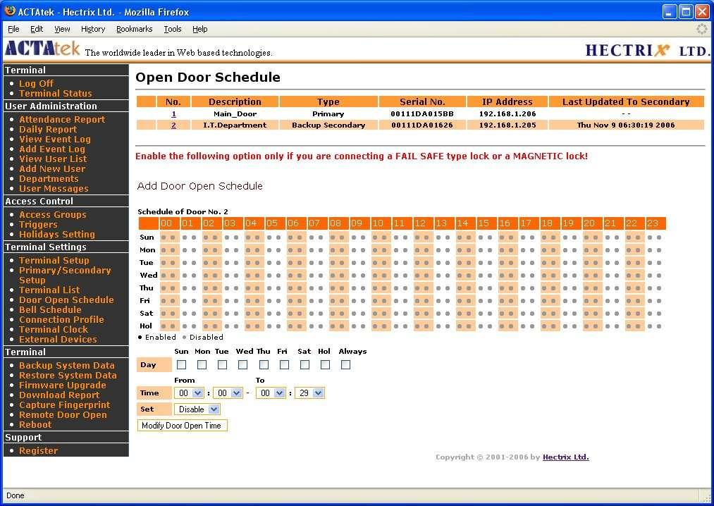
75 75

76 Bell Schedule The Bell Schedule option needs to be enabled via Door Strike 2 Option under Terminal Setup page. Once enabled, ACTAtek2 is able to trigger a bell wired to the door strike 2 connector for the scheduled time. 76

77 Terminal Clock The Terminal Clock can be modified according to the region you are in. It is extremely useful to have a correct timing for all time attendance purposes or for reporting purposes since that s the time the system will record for any access. If the SNTP (Time server) is enabled, then the ACTAtek2TM will follow the time of the local time server, either provided by the government or other authorities in the region. If the SNTP is disabled, the ACTAtek2TM will either have to follow the time on the PC or a time can be set for the device according to the local time settings. To let ACTAtek2TM to follow the time on the PC, select On for Auto Adjust. To disable this auto adjust, select Off and the time setting will be available for users to input the New Date and New Time. Also, time can be set according to regional Time Zones as presented here. Click Set to save any modifications made. 77

78 External Devices To add any external devices, which include External Mifare Reader, or other smart card readers, the External Devices option can be used. To do so, click on External Devices under Terminal Settings, and the following page should be displayed. To add an external reader, select the 'Reader Type', the reader's Address, the trigger type and click Add once all fields are completed. Once added, the reader will appear in the 'External Reader List'. To make any modifications to the reader configuration, select the number, and the page will be displayed where changes can be made. To delete the reader, select the check box and click 'Delete'. When you connect external devices to the ACTAtek2, Firmware and above will autodetect the the devices. 78
ACTAtek. Operation Manual
 ACTAtek TM Operation Manual Last revised: September 19, 2006 For more information and updated Manual, please visit our web site at http://www.hectrix.com OR http://www.actatek.com Information to user:
ACTAtek2 Manual. Version 1.4 Aug 14th, 2007 Hectrix Limited
 ACTAtek2 Manual Version 1.4 Aug 14th, 2007 Hectrix Limited Revision History Revision Date Description Author 1.0 2006/09/19 Initial Release Clement 1.1 2007/01/17 Format revised Ken 1.2 2007/04/27 Address
ACTAtek Server Manual
 Version 1.0.16pre35 Apr 27, 2007 Hectrix Limited Revision History Revision 1.0 Date Description 2005/07/27 - Initial Release Author Cheong - Updated Pictures and Contents 1.1 2006/11/09 - Added chapters
ACTAtek External IP Smartcard Reader Manual
 ACTAtek External IP Smartcard Reader Manual Version 1.4 November 5, 2012 ACTAtek Pte Ltd Revision History Revision Date Description Author 1.0 2011/10/02 Initial Release Allan 1.2 2012/04/12 Diode is required
Workstar iguard. Access Control & Time Attendance System with fingerprint sensor
 Workstar iguard Access Control & Time Attendance System with fingerprint sensor Workstar iguard Access Control & Time Attendance System with fingerprint reader iguard is a Biometrics (fingerprint identification)
A-1300 Biometric Access Control System USER'S MANUAL
 A-1300 Biometric Access Control System USER'S MANUAL Table of Contents 1. General Information... 1 1.0 Notification... 2 1.1 System Overview... 2 1.2 Main Features... 2 1.3 Equipment... 3 2. Basic Concepts...
Copyright 2009, NITGEN&COMPANY Co., Ltd. All rights reserved.
 Copyright 2009, NITGEN&COMPANY Co., Ltd. All rights reserved. ` Unauthorized reproduction of part or all of this manual s content in any form is prohibited. Product specifications may change without prior
Pilot Engineering HK Ltd.
 Built-in Web Server The built-in Web Server enables all the computers in the corporate network to directly & simultaneously access the device using any Internet Browser, such as Microsoft Internet Explorer,
User Manual. BioTime Web
 BioTime Web Version: 1.0 Date: December 2016 BioTime Web Index 1. Quick Start... 2 1.1. Overview... 2 1.2. Finger Placement... 3 1.3. How to use touch screen... 3 1.4. Recommended Operation Steps... 4
USER GUIDE. Preliminary
 USER GUIDE Preliminary Copyright 2009, NITGEN&COMPANY Co., Ltd. All rights reserved. ` Unauthorized reproduction of part or all of this manual s content in any form is prohibited. Product specifications
uface800 Time Clock User Manual uface800
 Innovative Time and Attendance Solutions uface800 Time Clock User Manual Version 3.6.3 uface800 Visit: MidexTimeAndAttendance.com Call: 1-888-544-7878 Email: info@midexsoftware.com /TimeAndAttendanceSoftware
Equitrac Embedded for Kyocera Mita. Setup Guide Equitrac Corporation Equitrac Corporation
 Equitrac Embedded for Kyocera Mita 1.3 Setup Guide 2012 Equitrac Corporation 2012 Equitrac Corporation Equitrac Embedded for Kyocera Mita Setup Guide Document Revision History Revision Date Revision List
F18. Fingerprint capacity 3,000 Transaction capacity 100,000 Hardware Platform ZK 6001, 400Mhz 64M Flash, 32MSDRAM. Identification speed
 F18 Features: 1. 2.4 TFT LCD color screen 2. Standard Wiegand Input and Output interfaces are compatible with most all 3 rd party 26 bit Wiegand readers and access control panels. 3. USB HOST port makes
1TouchXL & 1TouchXLS
 Manual 1TouchXL & 1TouchXLS Fingerprint Lock Operator s Manual Intelligent Biometric Controls, Inc. - www.fingerprintdoorlocks.com Rev. 2.2 Introduction I II III IV V VI VII Table Of Contents Introduction
BF-630X/BF-830X WEB SCREEN. Access Control/Time Attendance. User s Manual
 BF-630X/BF-830X Access Control/Time Attendance WEB SCREEN User s Manual Table of Contents CHAPTER 1 INSTALLATION... 2 Requirement...2 Procedure...2 CHAPTER 2 WEB SETUP DESCRIPTION... 3 Login Web...3 Preparation...3
Smart Access Control System Software. User Manual. Version 1.0
 Smart Access Control System Software User Manual Version 1.0 Copyright MaCaPS International Ltd. 2002 This manual was produced by MaCaPS International Ltd. MaCaPS International Ltd. http://www.macaps.com.hk
ACTAtek Certified Access Control Professional Text Book
 ACTAtek Certified Access Control Professional Text Book 1 Introduction The ACTAtek is a Linux, web-based Biometrics and RFID smart card ID management system for access control, time attendance and payroll
GV-AS200 Controller. Hardware Installation Guide
 GV-AS200 Controller Hardware Installation Guide Before attempting to connect or operate this product, please read these instructions carefully and save this manual for future use. 2008 GeoVision, Inc.
Warp 3. User s Manual
 Warp 3 User s Manual 28.7 copyright@28 Table of Contents 1 About WARP3 SERIES 2 Features 2.1 Characteristics 2.2 Support Functions 3 Operation window 4 User s Menu 4.1 For fingerprint verify user 4.2 For
ACTAtek Agent Manual
 Version 1.27 July 27, 2005 Hectrix Limited Revision History Revision Date Description Author 1 2005/07/27 Initial Release Cheong 2 3 4 5 6 7 8 9 10 11 12 13 14 15 16 17 18 19 20 21 22 23 24 25 26 27 28
Axxis Biometrics LLC. BioAxxis L113 Fingerprint Door Lock Programming Kit
 Axxis Biometrics LLC BioAxxis L113 Fingerprint Door Lock Programming Kit Revision 0.14 Dec 2005 Table of Contents 1. Introduction... 2 Product Overview... 2 Main Features... 2 Packing Lists... 3 2. Operation
Pegasus Equipments Export Limited. Local Contact:
 Pegasus Equipments Export Limited Add: #31G, Haiyige, Scienway Palace Science & Technology Industrial Park Shenzhen, China. Tel: +86 755 2658 3464 +86 755 2658 3596 Fax: +86 755 8611 0167 web: www.pegasusexport.com
T-7 FINGERPRINT TERMINAL. HARDWARE USER'S MANUAL Rev 1.1
 T-7 FINGERPRINT TERMINAL HARDWARE USER'S MANUAL Rev 1.1 1 Table of Contents 1. INTRODUCTION 1.1 SUPPLIED PART LIST 1.2 ABOUT PEGASUS T-7 1.3 HARDWARE SPECIFICATION 2. PRODUCT OVERVIEW 2.1 COMMUNICATION
User Manual. Before using this device, read and follow all instructions for safety
 User Manual Before using this device, read and follow all instructions for safety Copyrightc 2014 KJTECH Co., Ltd. All rights reserved. It is provided for informational purposes only in this manual. All
MorphoManager User Manual. Table of Contents
 User Manual Table of Contents Introduction... 4 Support... 4 Overview... 5 What is a client?... 5 What is a server?... 5 What is a fingerprint enrollment device?... 5 What is a MorphoAccess?... 6 What
Longshine Technologie Europe GmbH
 Longshine Technologie Europe GmbH www.longshine.de TABLE OF CONTENTS COPYRIGHT...2 1. INTRODUCTION...3 PRODUCT OVERVIEW...3 COMPONENTS AND FEATURES...3 HARDWARE INSTALLATION...3 2. MFP SERVER INSTALLATION...5
T9 Fingerprint Machine Hardware User Manual. Date: Version: 1.1
 T9 Fingerprint Machine Hardware User Manual Date: 2010.07.27 Version: 1.1 (c)2010 Copyright Pegasus Equipments Ltd. All Rights Reserved. 1 Table of Content Introduction... 3 Installation... 3 Menu Structure...
USER MANUAL. Disclaimer
 USER MANUAL Disclaimer The instructions in this document have been carefully checked for accuracy and are presumed to be reliable. Smart I Electronics Systems Pvt. Ltd. and its writers assume no responsibility
BioPointe. User's Manual
 BioPointe User's Manual Getting to know the BioPointe Notices: Information in this document is subject to change without notice. NO WARRANTY OF ANY KIND IS MADE WITH REGARD TO THIS MATERIAL INCLUDING,
FINGERPRINT TERMINAL HARDWARE USER'S MANUAL
 http://www.epordo.com 1 FINGERPRINT TERMINAL HARDWARE USER'S MANUAL or email us at info@securiticn.com 1 1. INTRODUCTION 1.1 SUPPLIED PART LIST 1.2 ABOUT 1.3 HARDWARE SPECIFICATION 2. PRODUCT OVERVIEW
Facial & Fingerprint Recognition Product
 Facial & Fingerprint Recognition Product Series User Manual Version: 1.1.7 Date: January 2010 About This Manual This document introduces the user interface and menu operations of the Facial & Fingerprint
Akcess BioMetrics Corporation. Bio2Touch. Access Control Fingerprint Reader. User's Manual. Akcess BioMetrics Corporation
 Akcess BioMetrics Corporation Bio2Touch Access Control Fingerprint Reader User's Manual Akcess BioMetrics Corporation Notices: Information in this document is subject to change without notice. NO WARRANTY
TABLE OF CONTENTS COPYRIGHT INTRODUCTION...3 PRODUCT OVERVIEW...3 COMPONENTS AND FEATURES...3 HARDWARE INSTALLATION
 TABLE OF CONTENTS COPYRIGHT...2 1. INTRODUCTION...3 PRODUCT OVERVIEW...3 COMPONENTS AND FEATURES...3 HARDWARE INSTALLATION...3 2. MFP SERVER INSTALLATION...5 PREPARATION...5 CONFIGURATION SOLUTION TABLE...5
Embedded for Xerox EPA-EIP Setup Guide
 Embedded for Xerox EPA-EIP Setup Guide 2016 XRX-EPA-EIP-20160315 Equitrac Embedded for Xerox EPA-EIP Setup Guide Document History Date Description of Revision Changes March 15, 2016 Updated for Equitrac
TZ 170 Quick Start Guide
 COMPREHENSIVE INTERNET SECURITY S o n i c WALL Internet Security Ap p l i a n c e s TZ 170 Quick Start Guide Quick Start Installation Thank you for purchasing a SonicWALL Internet security appliance. The
Quick Start Guide. ProBio & ProFAC + ZKBioSecurity 3.0
 Quick Start Guide ProBio & ProFAC + ZKBioSecurity 3.0 CONTENT 1 Safety Precautions...2 On Using Face Recognition Device...3 Device Overview...5 Product Dimensions & Installation...6 Power Connection...7
TL100C Features: Real-time 1-touch data export 3rd party hosted & non-hosted applications
 TL100C Features: Color TFT screen with GUI Interface for ease of use Optical Sensor 1 touch a-second user recognition Stores 3,000 templates and 100,000 transactions Reads Fingerprint and/or PINs integrated
Finger Vein Access Control device Quick Start Guide Version: 1.0 Date: June USB slot. USB slot
 Overview Fingerprint & Finger Vein Device Front Left Side: Finger Vein Device Touch screen Card reader Fingerprint reader Finger vein reader Finger vein sensor: During registration, after finger touches
PL- AC02B6 AZ Access Control User Manual
 PL- AC2B6 AZ Access Control User Manual 212..26 Content 1 About PL- AC2B6 AZ access controllers... 1 2 Main Features... 1 2.1 Features... 1 2.2 Functionality... 1 2.2.1 User account management... 1 2.2.2
INVISION TM IRIS TIME CLOCK USER GUIDE. InVision Iris Time Clock
 INVISION TM IRIS TIME CLOCK USER GUIDE InVision Iris Time Clock Copyright 2018 Paychex, Inc. All rights reserved. Paychex is a registered trademark and Paychex InVision is a trademark of Paychex, Inc.
Time Reorder Utility User Manual
 Time Reorder Utility User Manual Revisions...3 Introduction...4 Getting Started...5 Running Modes...7 Tray icon menu...7 Enter Password...8 Connections...8 Define Connections...8 Verify Connections...9
Operation manual For NG BIOSINGLE Version 1.1
 Operation manual For NG BIOSINGLE Version 1.1 SMART-I ELECTRONICS SYSTEMS PVT. LTD.(An ISO 9001:2008 certified company) R&D, Training & Customer Support Center: First Floor, Arihant Plaza Phase II, Village-Ovala,
YSOFT SAFEQ TERMINAL PROFESSIONAL 3.8 USER S GUIDE 1
 YSOFT SAFEQ TERMINAL PROFESSIONAL 3.8 USER S GUIDE 1 Copyright 2014 Y Soft Corporation. All rights reserved. Edition 2.0 [EN] Date: 5 October 2014 YSoft SafeQ, the YSoft SafeQ logo, and the Y Soft logo
BioSense II. (T/A System) WEB Configuration Manual
 WEB Configuration Manual") BioSense II (T/A System) WEB Configuration Manual 1.00.00, Jan/28/2014 (HW1.2) BioSense II (TA SYSTEM) Series: Web Ver1.1 Build Date: Jan/28/2014 Contents WEB Configuration...1 WEB Logon...1 Preparation...1
BioSense II (T/A System) WEB Configuration Manual 1.00.00, Jan/28/2014 (HW1.2) BioSense II (TA SYSTEM) Series: Web Ver1.1 Build Date: Jan/28/2014 Contents WEB Configuration...1 WEB Logon...1 Preparation...1
Equitrac Integrated for Océ
 Equitrac Integrated for Océ 1.2 Setup Guide 2014 Equitrac Integrated for Océ Setup Guide Document History Revision Date Revision List November 2, 2012 Updated for Equitrac Office/Express version 4.2.5
Integrated for Océ Setup Guide
 Integrated for Océ Setup Guide Version 1.2 2016 OCE-20160914 Equitrac Integrated for Océ Setup Guide Document History Revision Date September 14, 2016 Revision List New supported devices/card reader web
BRIVO ONSITE QUICK START GUIDE 09/14/17
 BRIVO ONSITE QUICK START GUIDE 09/14/17 Welcome to the The intent of this document is to get the Brivo Onsite system up and running as quickly as possible. Please consult the Administrator s Manual for
Equitrac Embedded for Sharp OSA. Setup Guide Equitrac Corporation
 Equitrac Embedded for Sharp OSA 1.4 Setup Guide 2012 Equitrac Corporation Equitrac Embedded for Sharp OSA Setup Guide Revision Date Revision List November 1, 2012 Updated for Equitrac Office/Express 4.2.5
C1002 IP Camera. Quick Installation Guide. Solwise Ltd., 1
 C1002 IP Camera Quick Installation Guide Solwise Ltd., www.solwise.co.uk, sales@solwise.co.uk 1 Trademarks and/or registered trademarks are the property of their respective owners The information presented
Installation & User Manual
 Contents Installation Instructions 3 Installation Diagrams 4 System Overview 6 Wiring Diagrams 8 Network Diagrams 9 Operation Instructions Fingerprint Enrollment 12 21 Wi-Enterprise Controller www.transmittersolutionssmart.com
CONFIGURATION MANUAL. English version
 CONFIGURATION MANUAL English version Frama F-Link Configuration Manual (EN) All rights reserved. Frama Group. The right to make changes in this Installation Guide is reserved. Frama Ltd also reserves the
Finger Authentication Server
 Futronic Technology Company Ltd. Finger Authentication Server User's Guide Version 5.7 Copyright 2003-2010 Futronic Technology Company Ltd. Copyright 2003-2010 Futronic Technology Company Ltd. All rights
SP2+ Swing Handle Lock Manual
 www.akcp.com SP2+ Swing Handle Lock Manual Copyright 2016, AKCP Table of Contents Introduction... 3 Hardware features... 4 LED status description for the Handle Lock & Door Sensor... 4 Specifications FAQ
Fingerprint Access Controller. enbioaccess-t1. User Guide
 Fingerprint Access Controller enbioaccess-t1 User Guide 2 Copyright 2013, NITGEN Co., Ltd. All rights reserved. ` This manual may not be reproduced, either wholly or in part, without prior permission.
DPtech IPS2000 Series Intrusion Prevention System User Configuration Guide v1.0
 DPtech IPS2000 Series Intrusion Prevention System User Configuration Guide v1.0 i Hangzhou DPtech Technologies Co., Ltd. provides full- range technical support. If you need any help, please contact Hangzhou
3.2 No records found though staff have clocked in/out The machine cannot connect with PC Clock s time works fine, but FP scanner
 1 2 Contents 1 Product Introduction... 2 1.1 Introduction... 2 1.1.1 Product Feature... 2 2 Operation Guide... 5 2.1 Keypad Introduction... 5 2.2 Time attendance status... 5 2.3 User... 5 2.3.1 User enroll...
PePWave Mesh Connector User Manual
 PePWave Mesh Connector User Manual Document Rev. 1.0 Jun-07 COPYRIGHT & TRADEMARKS Specifications are subject to change without notice. Copyright 1999-2007 PePWave Ltd. All Rights Reserved. PePWave and
Longshine Technologie Europe GmbH LCS-MFP101-2 Multifunction Printserver
 Longshine Technologie Europe GmbH LCS-MFP101-2 Multifunction Printserver www.longshine.de TABLE OF CONTENTS COPYRIGHT...2 1. INTRODUCTION...3 PRODUCT OVERVIEW...3 COMPONENTS AND FEATURES...3 HARDWARE INSTALLATION...3
Fingerprint Access Standalone User s Manual
 Fingerprint Access Standalone User s Manual V1.1.1 1 Table of Contents 1 Overview... 1 2 Device Structure and Installation... 2 2.1 Device Structure... 2 2.2 Device Installation... 3 3 System Structure...
ID
 CATLOG 1. Use notice... 1 1.1 the recommended procedure in the first using... 1 1.2 Button description... 2 2. User Management... 3 2.1 User Registration... 3 2.1.1 Fingerprint registration... 4 2.1.2
Operating Instructions
 Table of Contents Installation Overview General Installation Overview... Setting Up Your Machine Network Configuration... 4 Setting up the Network Configuration... 4 Installation Installing the Printer
Face & Fingerprint Recognition Product
 Realand Bio Co., LTD. Face & Fingerprint Recognition Product Hardware User Manual PRO6. Date: June 2016 Product Specification PC Software Version Cloud Based Version LCD Display 2.8 inch TFT Color Screen
USER MANUAL. BioPro SA50 Fingerprint & Palm Terminal. Version: 1.0 Date: August Inch TFT Terminal User Manual 1
 USER MANUAL BioPro SA50 Fingerprint & Palm Terminal Version: 1.0 Date: August. 2017 2.4 Inch TFT Terminal User Manual 1 About This Manual This manual introduces the operation of user interfaces and menu
SF200. Installation Guide & Quick Start Guide. 2 TFT AC Terminal Version: 1.0 Date: June 2014
 SF200 Installation Guide & Quick Start Guide 2 TFT AC Terminal Version: 1.0 Date: June 2014 All design and specification declared are subject to change without notice in advance. Contents Safety Precautions
ID
 User Manual 1. Usage Guidelines.... 1 1.1 The recommended procedure... 1 1.2 Button description.... 2 1.3 The initial interface and main menu... 2 1.4 Authentication methods... 3 2. Department set....
INSTALLATION GUIDE. Assign an IP Address and Access the Video Stream
 INSTALLATION GUIDE Assign an IP Address and Access the Video Stream Liability Every care has been taken in the preparation of this document. Please inform your local Axis office of any inaccuracies or
Introduction. Package Checklist. Minimum System Requirements. Registering Your Product. More Help
 Introduction Keep a watch on your family, pet, home or office 24/7, even when you re not there. Creative Live! Cam IP SmartHD gives you a live update on your phone, wherever you are. Get activity alerts,
Equitrac Integrated for Konica Minolta. Setup Guide Equitrac Corporation
 Equitrac Integrated for Konica Minolta 1.2 Setup Guide 2012 Equitrac Corporation Equitrac Integrated for Konica Minolta Setup Guide Document Revision History Revision Date Revision List November 1, 2012
H3C SecBlade SSL VPN Card
 H3C SecBlade SSL VPN Card Super Administrator Web Configuration Guide Hangzhou H3C Technologies Co., Ltd. http://www.h3c.com Document version: 5PW105-20130801 Copyright 2003-2013, Hangzhou H3C Technologies
Installation & User Manual V2.08
 YOUR SECURITY IS OUR PRIORITY Other products from GSD Contents Installation Instructions Installation Diagrams System Overview Wiring Diagrams Network Diagrams Operation Instructions Fingerprint Enrollment
Innovative Electronics for a Changing World INDEX
 Innovative Electronics for a Changing World INDEX 1. SYSTEM DESCRIPTION 2. BOARD CONNECTIONS terminals and indicators 3. CONNECTION DIAGRAM 4. START UP GUIDE and passwords 5. HOME PAGE 6. STATUS PAGE 7.
Fingerprint Door Lock OPERATOR S MANUAL
 Fingerprint Door Lock OPERATOR S MANUAL Notes: Please read this manual carefully before operation. 1 Contents Chapter 1: Introduction 03 1.1 Features 03 1.2 Technical Specification 03 1.3 Fingerprint recognition
C2 Pro User Manual Anviz Technology Co., Ltd.
 C2 Pro User Manual (V1.0) 2001-2015 Anviz Technology Co., Ltd. PREFACE Honorable customers: Thank you for choosing products from Anviz Technology Co.,Ltd. Our products contain world cutting edge technologies
Unit Door Station User's Manual ----VTO12XX Series
 Unit Door Station User's Manual ----VTO12XX Series V1.2.0 Welcome Thank you for purchasing our product! This quick start guide is designed to be a reference tool for your system. Please keep it well for
Self-Service Attendance Terminal User Manual
 Self-Service Attendance Terminal User Manual Version: 4.1 Date: May. 2014 Scope: SSR self-service attendance terminal with a firmware version later than V3.0, 2.8 inch network attendance machine About
Zodiac Max OPERATOR GUIDE
 Zodiac Max OPERATOR GUIDE February 2015 Table of Contents INTRODUCTION... 5 PC Requirements... 6 USB Driver Installation... 7 ZODIAC SINGLE-STATION SOFTWARE... 8 Software Installation... 8 Communications
M73 Series Network Projector Operation Guide
 M73 Series Network Projector Operation Guide V1.00 Copyright Copyright 2017 BenQ Corporation. All rights reserved. No part of this publication may be reproduced, transmitted, transcribed, stored in a retrieval
TSG 250. Fingerprint Identification Reader Operation & Installation Manual v1.0
 TSG 250 Fingerprint Identification Reader Operation & Installation Manual v1.0 TABLE OF CONTENTS SECTION 1 TSG-250 Installation Manual 1. Power... 4 2. LAN Communication... 4 4. Door Sensor/EXIT Button
Fingerprint Door Lock User MANUAL
 Fingerprint Door Lock User MANUAL Notes: Please read this manual carefully before operation. 0 User Manual AKME LOCK LLC Contents CHAPTER 1: INTRODUCTION... 2 1.1 FEATURES... 2 1.2 TECHNICAL SPECIFICATION...
ivms-4200 Access Control Client User Manual UD00895N
 ivms-4200 Access Control Client User Manual UD00895N User Manual About this Manual This Manual is applicable to ivms-4200 Access Control Client. The Manual includes instructions for using and managing
USER MANUAL. 4.3-inch Touch Screen & Palm Attendance Terminal. Version: 1.0 Date: August, 2017
 USER MANUAL 4.3-inch Touch Screen & Palm Attendance Terminal Version: 1.0 Date: August, 2017 I Important Statement Thank you for choosing our product. Please read this manual carefully to avoid damage
Broadband Router DC-202. User's Guide
 Broadband Router DC-202 User's Guide Table of Contents CHAPTER 1 INTRODUCTION... 1 Broadband Router Features... 1 Package Contents... 3 Physical Details...3 CHAPTER 2 INSTALLATION... 5 Requirements...
NCOM SERIAL DEVICE SERVER 1XX SERIES USER S MANUAL
 NCOM SERIAL DEVICE SERVER 1XX SERIES USER S MANUAL 2017-07-07 Edition Titan Electronics Inc. Web: www.titan.tw Contents 1. INTRODUCTION... 4 1.1 Key Features... 5 1.2 Specifications... 6 2. PANEL LAYOUT
AirCruiser G Wireless Router GN-BR01G
 AirCruiser G Wireless Router GN-BR01G User s Guide i Contents Chapter 1 Introduction... 1 Overview...1 Features...1 Package Contents...2 AirCruiser G Wireless Router Rear Panel...2 AirCruiser G Wireless
Application. Contents of Package. Inspect the CyberSwitch upon receipt. The package should contain the following items:
 Overview CyberPower power manager CyberSwitch is the ultimate power control center to manage multiple network devices via the Internet. After installing the hardware and setting up an IP address, this
Access Control System
 Access Control System Version 3.0 Hardware and Software Installation Guide Long Range RFID (UHF) Readers and Tags Specialist Smart Key Access Control System Installation Guide i Smart Key Contact Information
DG-HR1160M Portable Power Bank 3G Router User Manual
 DG-HR1160M Portable Power Bank 3G Router User Manual V1.0 2013-11-14 As our products undergo continuous development the specifications are subject to change without prior notice COPYRIGHT Copyright 2013
AM-101 AM-101AirMedia Presentation Gateway. Supplemental Guide Crestron Electronics, Inc.
 AM-101 AM-101AirMedia Presentation Gateway Supplemental Guide Crestron Electronics, Inc. Crestron software, including without limitation, product development software and product operating system software
NX1700EIB02 (Supercedes NX1700EIA02) NetworX Series. NX-1700E Proximity Card Reader Installation and Startup
 NetworX Series. NX-1700E Proximity Card Reader Installation and Startup") NX1700EIB02 (Supercedes NX1700EIA02) NetworX Series NX-1700E Proximity Card Reader Installation and Startup 2002 GE Interlogix All rights reserved. Printed in the United States of America. These instructions
NX1700EIB02 (Supercedes NX1700EIA02) NetworX Series NX-1700E Proximity Card Reader Installation and Startup 2002 GE Interlogix All rights reserved. Printed in the United States of America. These instructions
Simple Card Reader for Door Access & Time Attendance System. User Guide
 Simple Card Reader for Door Access & Time Attendance System User Guide 3 CHAPTER 1 GETTING STARTED Viewing the User Guide in the Internet Included Accessories Included Printed Materials Activating m-kadex
Time Attendance User s Manual
 Time Attendance User s Manual V1.0.0 1 Table of Contents Table of Contents... 2 1 Product Overview... 1 1.1 Introduction... 1 2 Installation Guide... 1 2.1 Checklist... 1 2.2 Panel and Interface... 1 2.3
ACCESS CONTROL QUICK INSTALL GUIDE. tel: +44 (0) fax: +44 (0) web:
 fax: +44 (0) web:") ACCESS CONTROL QUICK INSTALL GUIDE tel: +44 (0)1457 874 999 fax: +44 (0)1457 829 201 email: sales@cop-eu.com web: www.cop-eu.com WIRING CONFIGURATION - ACS CONTROLLERS CONNECTIONS Dahua access controllers
ACCESS CONTROL QUICK INSTALL GUIDE tel: +44 (0)1457 874 999 fax: +44 (0)1457 829 201 email: sales@cop-eu.com web: www.cop-eu.com WIRING CONFIGURATION - ACS CONTROLLERS CONNECTIONS Dahua access controllers
Network Guide. IMPORTANT: Read this manual carefully before using your printer. Save this manual for future reference. ENG
 Network Guide IMPORTANT: Read this manual carefully before using your printer. Save this manual for future reference. ENG Network Guide How This Manual Is Organized Chapter 1 Before You Start Chapter 2
NETWORK USER S GUIDE. Multi-Protocol On-board Ethernet Multi-function Print Server and Wireless Ethernet Multi-function Print Server
 Multi-Protocol On-board Ethernet Multi-function Print Server and Wireless Ethernet Multi-function Print Server NETWORK USER S GUIDE This Network User's Guide provides useful information of wired and wireless
CHAPTER 7 ADVANCED ADMINISTRATION PC
 ii Table of Contents CHAPTER 1 INTRODUCTION... 1 Broadband ADSL Router Features... 1 Package Contents... 3 Physical Details... 4 CHAPTER 2 INSTALLATION... 6 Requirements... 6 Procedure... 6 CHAPTER 3 SETUP...
TSS-7/TSS-10 7" and 10.1" Room Scheduling Touch Screens
 TSS-7/TSS-10 7" and 10.1" Room Scheduling Touch Screens Supplemental Guide Crestron Electronics, Inc. Crestron product development software is licensed to Crestron dealers and Crestron Service Providers
Portable Data Collector Series Z-9000 ( Version 1.0) User s Manual ZEBEX INDUSTRIES INC.
 User s Manual ZEBEX INDUSTRIES INC.") Portable Data Collector Series Z-9000 ( Version 1.0) User s Manual ZEBEX INDUSTRIES INC. WWW.ZEBEX.COM Revision History Changes to the original manual are listed below: Version Date Description of Version
Portable Data Collector Series Z-9000 ( Version 1.0) User s Manual ZEBEX INDUSTRIES INC. WWW.ZEBEX.COM Revision History Changes to the original manual are listed below: Version Date Description of Version
FW3170 User s Manual (Product Guide)
") FW3170 User s Manual (Product Guide) Version 4.14(Rev.E) April 13, 2012 Class A Digital Device (industrial & commercial environment) This equipment has been tested and found to comply with the limits for
FW3170 User s Manual (Product Guide) Version 4.14(Rev.E) April 13, 2012 Class A Digital Device (industrial & commercial environment) This equipment has been tested and found to comply with the limits for
Installation and Configuration Guide
 Installation and Configuration Guide h-series 800-782-3762 www.edgewave.com 2001 2011 EdgeWave Inc. (formerly St. Bernard Software). All rights reserved. The EdgeWave logo, iprism and iguard are trademarks
User s Guide [Security Operations]
![User s Guide [Security Operations]](/thumbs/74/70955793.jpg "User s Guide [Security Operations]") User s Guide [Security Operations] 006.1 Ver. 1.0 Contents Contents 1 Security 1.1 Introduction... 1- Compliance with the ISO15408 Standard... 1- Operating Precautions... 1- INSTALLATION CHECKLIST... 1-3
User s Guide [Security Operations] 006.1 Ver. 1.0 Contents Contents 1 Security 1.1 Introduction... 1- Compliance with the ISO15408 Standard... 1- Operating Precautions... 1- INSTALLATION CHECKLIST... 1-3