netgateway DTM for nettap and netbrick
|
|
|
- Clemence Warner
- 5 years ago
- Views:
Transcription

1 Operating Instructions Manual netgateway DTM for nettap and netbrick Configuration of Gateway Devices Hilscher Gesellschaft für Systemautomation mbh DOC081201OI02EN Revision 2 English Released Public
2 Introduction 2/172 Table of Contents 1 INTRODUCTION About this Manual Online Help List of Revisions Conventions in this Manual Legal Notes Copyright Important Notes Exclusion of Liability Warranty Export Regulations Registered Trademarks About netgateway DTM Requirements Dialog Structure of the netgateway DTM General Device Information Navigation Area Dialog Panes Controls and Dialog Buttons Status Bar CONFIGURATION OF NT 100 AS GATEWAY SETTINGS Overview Settings Driver Selecting the Driver Device Assignment Scanning for Devices Selecting the Device CONFIGURATION Overview Configuration Settings Licensing Which licenses are present in the Device? How to order a license How to get the License and transfer it to the Device Signal Mapping Status Information Memory Card Management Configuration EtherCAT Master Configuration EtherCAT Slave EtherCAT Slave Parameter Settings at the used EtherCAT Master Configuration EtherNet/IP Scanner... 57
3 Introduction 3/ Configuration EtherNet/IP Adapter EtherNet/IP Adapter Parameter Settings at the used EtherNet/IP Scanner Configuration Open Modbus/TCP Open Modbus/TCP Parameter Command Table Open Modbus/TCP Open Modbus/TCP Server Settings at the used Open Modbus/TCP Client Modbus References Configuration POWERLINK Controlled Node POWERLINK Controlled Node Parameter Settings at the used POWERLINK Managing Node Configuration PROFINET IO Controller Configuration PROFINET IO Device (Gateway) PROFINET IO Device Parameter Settings at the used PROFINET IO Controller Configuration SERCOS III Slave SERCOS III Slave Parameter Settings at the used SERCOS III Master Configuration CANopen Master Configuration CANopen Slave CANopen Slave Parameter Settings at the used CANopen Master Configuration CC-Link Slave CC-Link Slave Parameter Settings at the used CC-Link Master Configuration DeviceNet Master Configuration DeviceNet Slave DeviceNet Slave Parameter Settings at the used DeviceNet Master Configuration PROFIBUS-DP Master Configuration PROFIBUS-DP Slave PROFIBUS-DP Slave Parameter Settings at the used PROFIBUS-DP Master Configuration Modbus RTU Master/Slave Modbus RTU Parameter Modbus RTU Master Modbus RTU Slave Modbus References Configuration ASCII ASCII Settings ASCII Parameters Settings for the ASCII Remote Device Configuration Serial with netscript netscript Settings Settings for the ASCII Remote Device Signal Configuration
4 Introduction 4/172 5 DIAGNOSIS Overview Diagnosis General Diagnosis Firmware Diagnosis ONLINE FUNCTIONS Connecting/Disconnecting Device Download Configuration ERROR NUMBERS Error Code Definition Overview Error Numbers General Hardware Error Codes RCX Errors - MID_SYS Task Error Codes RCX Errors - Common Status Codes RCX Errors - Status & Error Codes ODM Error Codes General ODM Error Codes General ODM Driver Error Codes ODM cifx Driver Specific Errors ODM DBM V4 Error Codes LISTS List of Figures List of Tables GLOSSARY APPENDIX User Rights Settings Configuration References Contacts
5 Introduction 5/172 1 Introduction 1.1 About this Manual This manual provides information on how to set and configure the device parameters of a nettap NT 100 device respectively a netbrick NB 100 device using the netgateway DTM, and what can be read from the diagnosis panes. Dialog Panes The table below gives an overview for the individual dialog panes descriptions: Section Subsection Page Settings Configuration Diagnosis Table 1: Descriptions Dialog Panes Overview Settings 29 Driver 30 Device Assignment 31 Overview Configuration 35 Settings 36 Licensing 37 Signal Mapping 45 Memory Card Management 52 Overview Diagnosis 141 General Diagnosis 142 Firmware Diagnosis 145
6 Introduction 6/ Online Help The netgateway DTM contains an integrated online help facility. To open the online help, click on the Help button or press the F1 key List of Revisions Index Date Version Component Chapter Revision x x netgatewaydtm.dll netgatewaygui.ocx x.x netgatewaydtm.dll netgatewaygui.ocx all created Expanded to 19 protocols
7 Introduction 7/ Conventions in this Manual Operation instructions, a result of an operation step or notes are marked as follows: Operation Instructions: <instruction> Or 1. <instruction> 2. <instruction> Results: <result> Notes: Important: <important note> Note: <note> <note, were to find further information>
8 Introduction 8/ Legal Notes Copyright Important Notes 2008 Hilscher Gesellschaft für Systemautomation mbh All rights reserved. The images, photographs and texts in the accompanying material (user manual, accompanying texts, documentation, etc.) are protected by German and international copyright law as well as international trade and protection provisions. You are not authorized to duplicate these in whole or in part using technical or mechanical methods (printing, photocopying or other methods), to manipulate or transfer using electronic systems without prior written consent. You are not permitted to make changes to copyright notices, markings, trademarks or ownership declarations. The included diagrams do not take the patent situation into account. The company names and product descriptions included in this document may be trademarks or brands of the respective owners and may be trademarked or patented. Any form of further use requires the explicit consent of the respective rights owner. The user manual, accompanying texts and the documentation were created for the use of the products by qualified experts, however, errors cannot be ruled out. For this reason, no guarantee can be made and neither juristic responsibility for erroneous information nor any liability can be assumed. Descriptions, accompanying texts and documentation included in the user manual do not present a guarantee nor any information about proper use as stipulated in the contract or a warranted feature. It cannot be ruled out that the user manual, the accompanying texts and the documentation do not correspond exactly to the described features, standards or other data of the delivered product. No warranty or guarantee regarding the correctness or accuracy of the information is assumed. We reserve the right to change our products and their specification as well as related user manuals, accompanying texts and documentation at all times and without advance notice, without obligation to report the change. Changes will be included in future manuals and do not constitute any obligations. There is no entitlement to revisions of delivered documents. The manual delivered with the product applies. Hilscher Gesellschaft für Systemautomation mbh is not liable under any circumstances for direct, indirect, incidental or follow-on damage or loss of earnings resulting from the use of the information contained in this publication.
9 Introduction 9/ Exclusion of Liability Warranty The software was produced and tested with utmost care by Hilscher Gesellschaft für Systemautomation mbh and is made available as is. No warranty can be assumed for the performance and flawlessness of the software for all usage conditions and cases and for the results produced when utilized by the user. Liability for any damages that may result from the use of the hardware or software or related documents, is limited to cases of intent or grossly negligent violation of significant contractual obligations. Indemnity claims for the violation of significant contractual obligations are limited to damages that are foreseeable and typical for this type of contract. It is strictly prohibited to use the software in the following areas: for military purposes or in weapon systems; for the design, construction, maintenance or operation of nuclear facilities; in air traffic control systems, air traffic or air traffic communication systems; in life support systems; in systems in which failures in the software could lead to personal injury or injuries leading to death. We inform you that the software was not developed for use in dangerous environments requiring fail-proof control mechanisms. Use of the software in such an environment occurs at your own risk. No liability is assumed for damages or losses due to unauthorized use. Although the hardware and software was developed with utmost care and tested intensively, Hilscher Gesellschaft für Systemautomation mbh does not guarantee its suitability for any purpose not confirmed in writing. It cannot be guaranteed that the hardware and software will meet your requirements, that the use of the software operates without interruption and that the software is free of errors. No guarantee is made regarding infringements, violations of patents, rights of ownership or the freedom from interference by third parties. No additional guarantees or assurances are made regarding marketability, freedom of defect of title, integration or usability for certain purposes unless they are required in accordance with the law and cannot be limited. Warranty claims are limited to the right to claim rectification.
10 Introduction 10/ Export Regulations Registered Trademarks The delivered product (including the technical data) is subject to export or import laws as well as the associated regulations of different counters, in particular those of Germany and the USA. The software may not be exported to countries where this is prohibited by the United States Export Administration Act and its additional provisions. You are obligated to comply with the regulations at your personal responsibility. We wish to inform you that you may require permission from state authorities to export, re-export or import the product. Windows 2000/Windows XP are registered trademarks of Microsoft Corporation. All other mentioned trademarks are property of their respective legal owners.
11 Introduction 11/ About netgateway DTM Requirements You can use the netgateway DTM to configure a nettap NT 100 device respectively a netbrick NB 100 device within a FDT Framework. System Requirements Windows 2000/ Windows XP DVD ROM drive Graphic resolution: min x 768 pixel Keyboard and Mouse Requirements netgateway DTM To configure a nettap NT 100 device or a netbrick NB 100 device with a DTM the following requirements have to be accomplished: Completed hardware installation of a nettap NT 100 device respectively a netbrick NB 100 device, where at least a base firmware has to be loaded in the device Installed FDT/DTM V 1.2 compliant frame application Loaded DTM in the Device Catalog of the FTD Framework
12 Introduction 12/ Dialog Structure of the netgateway DTM The graphical user interface of the DTM is composed of different areas and elements listed hereafter: 1. A header area containing the General Device Information, 2. The Navigation Area (area on the left side), 3. The Dialog Pane (main area on the right side), 4. The general buttons OK, Cancel, Apply, Help, 5. The Status Line containing information e. g. the online-state of the DTM. General Device Information Navi gation Area Dialog Pane OK Cancel Apply Help Status Line Figure 1: Dialog Structure of netgateway DTM
13 Introduction 13/ General Device Information Parameter Meaning IO Device Name of the device Vendor Vendor name of the device Device ID Identification number of the device Vendor ID Identification number of the vendor Table 2: General Device Information Navigation Area The Navigation Area at the left side of the dialog provides a tree structure to navigate through the panes of the DTM. Navigation Area Settings Driver Device Assignment Configuration Figure 2: Navigation Area To access a DTM pane select the respective item of the navigation tree structure. The Navigation Area can be hidden or it can be displayed again. Control Table 3: Hide / display Navigation Meaning Window button to hide the navigation area, (at the right side of the navigation title bar). Show navigation area button to open the navigation area, (at the lower left corner of the dialog pane).
14 Introduction 14/ Dialog Panes At the dialog pane the Settings, Configuration, Diagnosis/Extended Diagnosis or the Additional Tools panes are opened via the corresponding folder in the navigation area. Settings Driver Device Assignment Configuration Setting Licensing Signal Mapping Memory Card Management Diagnosis Diagnosis Table 4: Overview Dialog Panes On the pane Driver you can select a driver from the driver list. For further information, refer to section Driver on page 30. On the pane Device Assignment you must select the device and assign the device to the driver. For further information, refer to section Device Assignment on page 31. The Settings pane serves for selection of the protocols for the Gateway respectively the Proxyfunctionality. For further information, refer to section Settings on page 36. On the pane Licensing you can verify which licenses are available in the nettap NT 100 device, order licenses and transfer license files into the nettap NT 100 device. For further information, refer to section Licensing on page 37. On the pane Signal Mapping you can map the signals (I/O Data) of port X2 to the signals (I/O data) of port X3. For further information, refer to section Signal Mapping on page 45. On the pane Memory Card Management you can backup and resotore the firmware and the configuration to respectively from an MMC card. For further information, refer to section Memory Card Management on page 52. At the Diagnosis panes diagnosis information can be read. For further information, refer to section Overview Diagnosis on page 141. Note: Accessing the Diagnosis panes of the netgateway DTM requires an online connection from the netgateway DTM to the nettap NT 100 device respectively to the netbrick NB 100 device. For further information, refer to section Connecting/Disconnecting Device on page 146.
15 Introduction 15/ Controls and Dialog Buttons General Buttons In this section, you will find general information on controls and buttons. The table below explains the general buttons in the DTM user interface. Button OK Cancel Apply Help Meaning Table 5: General Buttons To confirm your latest settings, click on the OK button. All changed values will be applied on the frame application database. The dialog then closes. To cancel your latest changes, click on the Cancel button. Answer to the safety query Configuration data has been changed. Do you want to save the data? by Yes, No or Cancel. Yes: The changes are saved or the changed values are applied on the frame application database. The dialog then closes. No: The changes are not saved or the changed values are not applied on the frame application database. The dialog then closes. Cancel: Back to the DTM. To confirm your latest settings, click on the Apply button. All changed values will be applied on the frame application database. The dialog remains opened. To open the DTM online help, click on the Help button Table Line Buttons To select, create or delete a line in a table use the buttons shown in the table below. Button Meaning To select the first line of a table use the button First Line. To select the previous line of a table use the button Previous Line. To select the next line of a table use the button Next Line. To select the last line of a table use the button Last Line. The button Create a new Line inserts new lines into the table. The button Delete selected Line deletes the selected line from the table. Table 6: Table Line Buttons
16 Introduction 16/ Status Bar The Status Bar displays information about the current state of the DTM. The current activity, e.g. download, is signaled graphically via icons in the status bar. Figure 3: Status Bar Status Fields 1 to 6 Status Field Icon / Meaning 1 DTM Connection States 2 Data Source States Connected: Icon closed = Device is online Disconnected: Icon opened = Device is offline Data set: The displayed data are read out from the instance data set (database). Device: The displayed data are read out from the device. 3 States of the instance Date Set Valid Modified: Parameter is changed (not equal to data source). 4 Changes directly made on the Device Load/configure diagnosis parameters: Diagnosis is activated. 6 Device Diagnosis Status Table 7: Status Bar Icons [1] Save operation succeeded: The save operation has been successful. Further messages due to successful handling of device data. Firmware Download: Firmware Download is running Save operation failed: The save operation has failed. Further fail operation messages due to incorrect communication due to malfunction in the field device or its peripherals. Offline State Save operation succeeded Firmware Download Firmware Download sussessful Online State and Diagnosis Figure 4: Status Bar Display Examples
17 Configuration of NT 100 as Gateway 17/172 2 Configuration of NT 100 as Gateway The configuration of the NT 100 devices is explained exemplarily with the protocol conversion PROFINET IO Device to PROFIBUS-DP Master. The device NT 100-RE-DP with one master license is necessary for the protocol conversion from PROFINET IO Device to PROFIBUS-DP Master. The following steps have to be done to configure the device: 1. Start SYCON.net Select Start > Programs > SYCON.net System Configurator > SYCON.net SYCON.net is started 2. User Login In the window SYCON.net User Login press the button OK to login or enter your password and then press the button OK to login SYCON.net frame application appears 3. Create new project Select the menu File > New to create a new project An empty project is created 4. Insert NT 100-XX-XX device into the configuration Go to the device catalog under vendor Hilscher GmbH to the category Gateway. Use drag and drop with the NT 100-XX-XX device to insert it at the bus line. The NT 100-XX-XX device appears in the project
18 Configuration of NT 100 as Gateway 18/ Open the Gateway configuration window Select from the context menu of the NT 100-XX-XX symbol (right mouse click) the entry Configuration > Gateway The Gateway configuration window opens Select in the Navigation area Configuration > Settings The configuration window Settings opens
 the")
19 Configuration of NT 100 as Gateway 19/ Select the protocol for the primary network and for the secondary network and apply Select in the window Configuration > Settings at Protocol Combinations for the Primary Network (Port X2) the protocol PROFINET IO Device Select then at Protocol Combinations for the Secondary Network (Port X3) the protocol PROFIBUS-DP Master Click the button Apply The Gateway configuration window shows the following
 Select from the context menu of the NT 100-XX-XX symbol the entry Configuration > PROFINET IO Device The PROFINET IO Device configuration")
20 Configuration of NT 100 as Gateway 20/ Close the Gateway configuration window Click on the button OK The Gateway configuration window closes 8. Configure the protocol at the primary network (Port X2) Select from the context menu of the NT 100-XX-XX symbol the entry Configuration > PROFINET IO Device The PROFINET IO Device configuration window opens Set the parameters. Set especially the number of Input Data Bytes and Output Data Bytes. More information about PROFINET IO Device parameter is in section Configuration PROFINET IO Device (Gateway) on page 81.
21 Configuration of NT 100 as Gateway 21/ Close the configuration window Click on the button OK The configuration window closes 10. Insert the PROFIBUS-DP Slave devices into the PROFIBUS network (Secondary network) Missing PROFIBUS-DP Slave devices can be added to the device catalog using the menu Network > Import Device Descriptions. Import the GSD file of the PROFIBUS-DP Slave. Then select Network > Device Catalog Then click the button Reload Catalog Go to the device catalog. Use drag and drop with one or more PROFIBUS-DP Slave devices to insert it/them at the PROFIBUS bus line. The PROFIBUS-DP Slave device icons appear at the PROFIBUS network line (Secondary network) 11. Configure the PROFIBUS-DP Slave device Open the configuration window with a double click on the device icon of the PROFIBUS-DP Slave The configuration window of the PROFIBUS-DP Slave device opens More information about the configuration of PROFIBUS-DP Slave devices are in the document PROFIBUS_Generic_Slave_DTM_en.pdf in section Configuration 12. Open the PROFIBUS-DP Master (Port X3) configuration window Select from the context menu of the NT 100-XX-XX symbol the entry Configuration > PROFIBUS-DP Master The PROFIBUS-DP Master configuration window opens
22 Configuration of NT 100 as Gateway 22/ Configure the PROFIBUS-DP Master Set the parameter. Set especially under Configuration > Bus Parameter the bus parameter and under Configuration > Stationtable the station addresses (stations addresses of the PROFIBUS-DP Slave devices) More information about the configuration of PROFIBUS-DP Master devices are in the document PROFIBUS_Master_netX_DTM_en.pdf in section Configuration 14. Close the configuration window Click on the button OK The configuration window closes 15. Open the Gateway configuration window Select from the context menu of the NT 100-XX-XX symbol the entry Configuration > Gateway The Gateway configuration window opens

23 Configuration of NT 100 as Gateway 23/ Open the Signal Mapping window Select Configuration > Signal Mapping The window Signal Mapping opens
24 Configuration of NT 100 as Gateway 24/ Signal Mapping: Data transfer from Port X2 to Port X3 Map the signals, which are received on Port X2 (Port X2 receive), with signals, which should be sent on Port X3 (Port X3 send). For this, mark the signal received (Port X2) and the signal to be sent (Port X3) and the click the button Map Signals Or Map the signal using drag and drop. For this, drag the signal received (Port X2 receive) and drop it on the signal to be sent (Port X3 send) 18. Signal Mapping: Data transfer from Port X3 to Port X2 Map the signals, which are received on Port X3 (Port X receive), with signals, which should be sent on Port X2 (Port X2 send). For this, mark the signal received (Port X ) and the signal to be sent (Port X2) and the click the button Map Signals Or Map the signal using drag and drop. For this, drag the signal received (Port X3 receive) and drop it on the signal to be sent (Port X2 send) 19. Signal Mapping: Transfer status info of Port X2 to Port X3 If necessary, map the status information of Port X2 (Port X2 generated, which are generated device internal) to signals which should be sent on Port X3 (Port X3 send) For this mark the status signal (Port X2) and the signal which should be sent (Port X3) and click the button Map Signals Or Map the signal using drag and drop. For this, drag the status signal (Port X2 generated) and drop it on the signal to be sent (Port X3 send)
 to signals which should be sent")
25 Configuration of NT 100 as Gateway 25/ Signal Mapping: Transfer status info of Port X3 to Port X2 If necessary, map the status information of Port X3 (Port X3 generated, which are generated device internal) to signals which should be sent on Port X2 (Port X2 send) For this mark the status signal (Port X3) and the signal which should be sent (Port X2) and click the button Map Signals Or Map the signal using drag and drop. For this, drag the status signal (Port X3 generated) and drop it on the signal to be sent (Port X2 send) An example of the I/O Data Mapping window after steps 17 to 20 shows the following figure

26 Configuration of NT 100 as Gateway 26/ Connect the USB cable Connect with an USB cable the USB connector of the nettap device with the USB connector of the PC. 22. Select the USB driver Select Settings > Driver and then check USB Driver for netx The following figure shows the selected USB Driver

27 Configuration of NT 100 as Gateway 27/ Device Assignment Select Settings > Device Assignment Click the button Scan Check the found nettap device The following figure shows the assigned device
28 Configuration of NT 100 as Gateway 28/ Load Firmware Select Configuration > Settings Mark the Firmware file in section Firmware Download Click the button Download The firmware is loaded into the nettap device 25. Close the Gateway configuration window Click the button OK The Gateway configuration window closes 26. Download configuration Select from the context menu of the NT 100-XX-XX symbol the entry Download Answer the security question with Yes, if the download should start The configuration is transferred info the nettap device 27. Save project Select File > Save, enter a file name and save the project the project file is stored 28. Device Description File for the configuration of the Master Use for the configuration of the PROFINET IO Controller the device description file GSDML-V2.1-HILSCHER-NT 100-RE PNS xml from the CD from the directory EDS/PROFINET.
29 Settings 29/172 3 Settings 3.1 Overview Settings Settings Dialog Panes The table below gives an overview for the individual Settings dialog panes descriptions: Section Subsection Page Driver 30 Selecting the Driver 30 Device Assignment 31 Table 8: Descriptions Settings Scanning for Devices 32 Selecting the Device 34 Figure 5: Navigation Area - Settings Note: To edit the Settings dialog panes you need User Rights for Maintenance.
 Table 9: Driver Selection List Parameters 3.2.")
30 Settings 30/ Driver The Driver dialog pane displays the driver/s to be used for a netgateway DTM to device communication connection. Figure 6: Driver Selection List Parameter Meaning Driver Name of the driver Version Version of the driver ID ID of the driver (driver identification) Table 9: Driver Selection List Parameters Selecting the Driver To establish a connection you need to select a driver first. Note: Not all the drivers displayed necessarily support the device. The used driver must be supported by the device or must be available for the device. To select the driver/s to be used: 1. Select Settings > Driver in the navigation area. The available drivers are listed on the Driver dialog pane. Figure 7: Driver Selection List - recognized or installed Drivers 2. Check the checkbox for the driver/s in the selection list. Figure 8: Driver Selection List - Driver/s selected
31 Settings 31/ Device Assignment Note: To establish a connection from the netgateway DTM to a nettap NT 100 device, you first must assign a nettap NT 100 device to the netgateway DTM. Therefore you must assign the nettap NT 100 device to the selected driver. Therefore in the Device Assignment dialog pane you must scan for the nettap NT 100 device and select it. If the device shall get a new firmware: 1. first you must scan for the device and select it, 2. then you must download a firmware to the device
32 Settings 32/ Scanning for Devices 1. Select Settings > Device Assignment in the navigation area. The dialog pane Device Assignment is displayed. Figure 9: Device Assignment - detected Devices (* The name of the device class is displayed.) Example for a device with firmware 2. Select the list box entry suitable only. 3. Select the Scan button, to start the scanning process. Under Device Selection all devices are displayed, which can be connected to the netgateway DTM via the preselected driver.
33 Settings 33/172 Parameter Meaning Range of Value / Value Device selection Selecting suitable only or all devices. suitable only, all Device Hardware Port 0/1/2/3 Serial number Driver Device name. Shows, which hardware is assigned to which communication interface. Serial number of the device Name of the driver Channel Protocol Shows, which firmware is loaded to which device channel. The data for the used channel consists of the protocol class and the communication class. a.) For devices without firmware: Undefined Undefined, b.) For devices with firmware: e. g. PROFIBUS Master Access path (under Device selection last column on the right) Access path (at the lower side of the dialog pane) Depending on the used driver in the column Access path different data to the device are displayed. If under Device selection the check box for a device is checked, under Access path (at the lower side of the dialog pane) the driver identification or depending on the used driver additional data to the device. Table 10: Parameters of the Device Assignment Depending on the device and on the driver: board or channel number, IP address or COM interface driver identification (ID) depending on the device and on the driver: board or channel number, IP address or COM interface
34 Settings 34/ Selecting the Device Note: A connection with the netgateway DTM can only be established with one nettap NT 100 device. To select the physical nettap NT 100 device: 1. In the Device Assignment pane in the selection list Device selection check the check box for the device. Figure 10: Device Assignment - Selecting the Device Under Access path (below in the dialog pane) the access path to the device, e. g. the driver identification, or depending on the used driver additional access data of the device are displayed. 2. Select the Apply button, to apply the selection.
35 Configuration 35/172 4 Configuration 4.1 Overview Configuration Configuration Dialog Panes The table below gives an overview for the Configuration dialog panes descriptions: Section Page Settings 36 Licensing 37 Signal Mapping 45 Memory Card Management 52 Table 11: Descriptions of the Dialog Panes Configuration Figure 11: Navigation Area - Configuration
36 Configuration 36/ Settings In the Settings pane you can: select the protocol for Port X2 respectively for Port X3 transfer the firmware into the nettap NT 100 device set the cycle time of the Gateway

37 Configuration 37/ Licensing In the Licensing pane you can: check, which licenses are present in the device, order licenses, transfer license files to the device. Figure 12: License Pane
38 Configuration 38/ Which licenses are present in the Device? Check in the License pane which licenses are present in the device. Therefore click to the Master Protocols or Utilities folder to expand it. The column Existing indicates which licenses are present in the device. License for Protocols 1 General Master License. On the device maximally 1 communication protocol with master function can be implemented. 2 General Master Licenses. On the device maximally 2 communication protocols with master function can be implemented. License for Utilities SYCON.net, OPC Server, QVis or CoDeSys
39 Configuration 39/ How to order a license To order a license proceed as follows: Assign the device to the DTM, Select the required licenses, Enter the ordering data and Send your order via E Mail, Fax or Telephone Assigning the Device to the DTM Note: You first need to assign the device to the DTM. Only after this the device data and the available licenses are displayed in the License dialog. 1. Open the DTM configuration dialog via double click to the device symbol. 2. Select one or several driver/s. Select Settings > Driver in the navigation area. In the Driver pane check the checkbox for the driver/s. 3. Configure the driver, if necessary. Select in the navigation area Settings > Driver > [Name of the assigned driver]. Select Settings > Driver > [Name of the assigned driver] in the navigation area. In the drive dialog pane configure the driver settings. 4. Scan for the device/s. Select Settings > Device Assignment in the navigation area. In the Device Assignment pane select the list box entry suitable only or all. Select the Scan button, to start the scanning process. 5. Select the device and apply the selection. In the Device Assignment pane in the selection list Device selection check the check box for the device. Select the Apply button, to apply the selection. 6. Close the DTM configuration dialog via OK. For details to the device assignment, refer to section Overview Settings on page 29.
40 Configuration 40/ Selecting the License 1. Open the License pane: Therefore open the context menu, via right mouse click to the device symbol. From the context menu select Additional Functions > License. In the License pane: 2. Under License click to the Master Protocols folder to expand it. 3. In the column Order check the checkbox for the desired number of licenses: 1 General Master License or 2 General Master Licenses. And / Or: 4. Under License click to the Utilities folder to expand it. 5. In the column Order check the checkbox for: SYCON.net, OPC Server, QVis or CoDeSys.
41 Configuration 41/ Entering the Order Data 1. In the License pane under Name enter any obligatory order data. 2. Select in the list field [subsidiary] the entry for the subsidiary to which the order shall be send. Device Data (order data read from the device) The following order data read from the device are displayed in the License pane: Manufacturer Device number Serial number Chiptype Step (chip revision) Romcode revision Checksum (checksum of the device data) Data to manage the Order Mandatory data to the order request (editable fields in the License pane): Licensetype (User Single Device License): First Name Surname E Mail ( address, to which the license download link shall be send.) Telephone Fax Company Addresse Country City, State, Zip Additional order data, not mandatory (editable fields in the License pane): Order number Value added tax identification number
42 Configuration 42/ Ordering the License by E Mail Click to the button E Mail. A prepared ordering E Mail License request is opened, to the E Mail address of the subsidiary, to which the order shall be send. This ordering E Mail contains the automatically generated file OrderRequest_[Devicenumber]_[Serialnumber].xml with a summary info of the order information. Figure 13: Example: ordering E Mail License request Send the ordering E Mail License request. The order process is complete.
43 Configuration 43/ Ordering the License by Fax or by Telephone: Click to the button Print Fax Form or Telephone. Note: If your browser does not display the order data or the window Move Element or Copy Element are displayed, check the safety settings of your system. The summary of the ordering data PrintOrderRequest_ [Devicenumber]_[Serialnumber].html netx License Order Form is opend in a browser window. Figure 14: Example: order data form netx License Order Form Print out the order data form netx License Order Form and send it by fax. Or: Keep ready the order data form and communicate the order data via telephone. The order process is complete.
44 Configuration 44/ How to get the License and transfer it to the Device Licenses are delivered as license files. Note: License files can only be delivered via E Mail. The license file is delivered via E Mail. The E Mail contains a link to download the license file. After the license file has been delivered you must transfer the received license file into the device. 1. Download the license file *.nxl to your system. Therefore open the E Mail. Click to the Link for the Download of the license file and download it to your system. 2. Transfer the license file *.nxl to the device. In the License pane click to the button Download License. In the file selection window Open select the license file netx License Files (*.nxl) and click to the button Open. Then the license is present in the device an will be activated at the next reset of the device.
45 Configuration 45/ Signal Mapping The signal mapping determines which user data of the primary network are assigned to which user data of the secondary network and vice versa. With the mapping the received data from the primary network are mapped to the send data of the secondary network, the received data from the secondary network are mapped to the send data of the primary network, status information of the primary network are mapped to the send data of the secondary network, status information of the secondary network are mapped to the send data of the primary network. With this mapping a device internal list in generated. The device work each x ms through this list and copies the data.
46 Configuration 46/172 On the pane I/O Data Mapping you can map the I/O Data of port X2 to the I/O data of port X3. The I/O mapping is done the following way: Data transfer from Port X2 to Port X3 Map the signals, which are received on Port X2 (Port X2 receive), with signals, which should be send on Port X3 (Port X3 send). For this, mark the signal received (Port X2) and the signal to be send (Port X3) and the click the button Map Signals Or Map the signal using drag and drop. For this, drag the signal received (Port X2 receive) and drop it on the signal to be send (Port X3 send)
47 Configuration 47/172 Data transfer from Port X3 to Port X2 Map the signals, which are received on Port X3 (Port X receive), with signals, which should be send on Port X2 (Port X2 send). For this, mark the signal received (Port X ) and the signal to be send (Port X2) and the click the button Map Signals Or Map the signal using drag and drop. For this, drag the signal received (Port X3 receive) and drop it on the signal to be send (Port X2 send) Transfer status info of Port X2 to Port X3 If necessary, map the status information of Port X2 (Port X2 generated, which are generated device internal) to signals which should be send on Port X3 (Port X3 send) For this mark the status signal (Port X2) and the signal which should be send (Port X3) and click the button Map Signals Or Map the signal using drag and drop. For this, drag the status signal (Port X2 generated) and drop it on the signal to be send (Port X3 send) Transfer status info of Port X3 to Port X2 If necessary, map the status information of Port X3 (Port X3 generated, which are generated device internal) to signals which should be send on Port X2 (Port X2 send) For this mark the status signal (Port X3) and the signal which should be send (Port X2) and click the button Map Signals Or Map the signal using drag and drop. For this, drag the status signal (Port X3 generated) and drop it on the signal to be send (Port X2 send) Auto mapping The signal mapping can also be done automatically be the configuration software. Set Auto Mapping to From Port X3 to Port X2 and then click on Apply. The automatic signal mapping is done.

, others belong only to the master firmware status and are marked with Master.")
48 Configuration 48/ Status Information The status of the remote network coupled by the nettap NT 100 can be mapped into the I/O data. It contains the items shown in the figures for master and slave and are described below. Figure 15: Status information of the Master Figure 16: Status information of the Slave Some status information belong to the master firmware and to the slave firmware status and are marked with Master and Slave ), others belong only to the master firmware status and are marked with Master. Number of Active Slaves (Master) The firmware maintains a list of slaves within the remote network to which the remote network s master has successfully opened a connection. Ideally, the number of active slaves is equal to the number of configured slaves. This field holds the number of active slaves.
49 Configuration 49/172 Communication Change of State (Master and Slave) The communication change of state register contains information about the current operating status of the communication channel and its firmware unused, set to zero Status Ready (Bit 0) Running (Bit 1) Bus On (Bit 2) Configuration Locked (Bit 3) Configuration New (Bit 4) Restart Required (Bit 5) Restart Required Enable (Bit 6) Table 12: Communication Change of State COMM_COS_READY COMM_COS_RUN COMM_COS_BUS_ON COMM_COS_CONFIG_LOCKED COMM_COS_CONFIG_NEW COMM_COS_RESTART_REQUIRED COMM_COS_RESTART_REQUIRED_ENABLE The Communication Change of State Flags have the following meaning: Meaning The Ready flag is set as soon as the protocol stack is started properly. Then the protocol stack is awaiting a configuration. As soon as the protocol stack is configured properly, the Running flag is set, too. The Running flag is set when the protocol stack has been configured properly. Then the protocol stack is awaiting a network connection. Now both the Ready flag and the Running flag are set. The Bus On flag is set to indicate to the host system whether or not the protocol stack has the permission to open network connections. If set, the protocol stack has the permission to communicate on the network; if cleared, the permission was denied and the protocol stack will not open network connections. The Configuration Locked flag is set, if the communication channel firmware has locked the configuration database against being overwritten. Re-initializing the channel is not allowed in this state. The Configuration New flag is set by the protocol stack to indicate that a new configuration became available, which has not been activated. This flag may be set together with the Restart Required flag. The Restart Required flag is set when the channel firmware requests to be restarted. This flag is used together with the Restart Required Enable flag below. Restarting the channel firmware may become necessary, if a new configuration was downloaded from the host application or if a configuration upload via the network took place. The Restart Required Enable flag is used together with the Restart Required flag above. If set, this flag enables the execution of the Restart Required command in the netx firmware.
50 Configuration 50/172 Communication State (Master and Slave) The communication state field contains information regarding the current network status of the communication channel of the remote network. Depending on the implementation of the protocol stack of the remote network, all or a subset of the definitions below is supported. Status Value Unknown 0 Offline 1 Stop 2 Idle 3 Operate 4 Communication Channel Error (Master and Slave) This field holds the current error code of the communication channel of the remote network. If the cause of error is resolved, the communication error field is set to zero again. All values different from 0 indicate that an error has occurred. Errors may be signaled either from the operating system rcx or from the used protocol. Number of Configured Slaves (Master) The firmware maintains a list of slaves within the remote network to which the master has to open a connection. This list is derived from the configuration database created by SYCON.net. This field holds the number of configured slaves. Error Count (Master and Slave) This field holds the total number of errors detected since power-up within the remote network, respectively after reset. The protocol stack counts all sorts of errors in this field no matter if they were network related or caused internally. After power cycling, reset or channel initialization this counter is being cleared again. Error Log Indicator (Master and Slave) Note: This field is not yet supported.
51 Configuration 51/172 Number of Faulted Slaves (Master) If a slave of the remote network encounters a problem, it can provide an indication of the new situation to the master in certain Fieldbus systems. As long as those indications are pending and not serviced, this field holds a value unequal to zero. If no more diagnostic information is pending, the field is set to zero. Host Watchdog (Master and Slave) Note: This field is not yet supported. Slave Error Log Indicator (Master) Note: This field is not yet supported. Slave State (Master) The slave state field indicates whether the master of the remote network is in cyclic data exchange to all configured slaves. In case there is at least one slave missing or if the slave has a diagnostic request pending, the status is set to FAILED. For protocols that support non-cyclic communication only, the slave state is set to OK as soon as a valid configuration is found. Status Value Undefined 0 Ok 1 Failed 2 Version (Master and Slave) The version field holds the version number of this structure. The value is 1. Watchdog Timeout (Master and Slave) This field holds the configured watchdog timeout value of the protocol stack of the remote network. The value is specified in milliseconds.
52 Configuration 52/ Memory Card Management Note: This function is only available for the nettap NT 100 device family, because these devices have a MMC card slot. In the Memory Card management pane you can: backup the firmware and the configuration from the nettap device to an MMC memory card restore the firmware and the configuration from the MMC memory card into the nettap device On the pane MMC Management you can backup and restore the firmware and the configuration to respectively from an MMC card. The Folder on the pane shows the directory structure of the file system of the nettap device named SYSVOLUME and if an MMC card is inserted also the directory structure of the MMC card named SDMMC. Backup: To backup the firmware and configuration files insert a formatted (Format FAT) MMC card into the MMC slot of the nettap NT 100 device. When the directory named SDMMC is shown, then click on the button Backup to copy the firmware and configuration files from the nettap NT 100 device to the MMC card. Restore: To load the firmware and configuration files from an MMC card into the nettap NT 100 device, insert an MMC card into the MMC slot of the nettap NT 100 device which contains the firmware and configuration files. When the directory named SDMMC is shown, then click the button Restore to copy the firmware and configuration files from the MMC card into the nettap NT 100 device.
53 Configuration 53/ Configuration EtherCAT Master The nettap NT 100 device respectively the netbrick NB 100 device as EtherCAT Master needs a configuration, e. g. information about how many EtherCAT Slave devices with how many input and output data are to be connected. 1. Insert EtherCAT Slave devices Drag from the device catalog EtherCAT Slave device(s) and drop it to the bus line of the EtherCAT Master. 2. Configure EtherCAT Slave devices Open the configuration dialog for each EtherCAT Slave device and configure the device. Information about how to configure the EtherCAT Slave device is in the operating instruction manual Generic DTM for EtherCAT Slave devices and has the file name EtherCAT_GenericSlave_DTM_en.pdf respectively open in the configuration dialog of the slave the online help by the F1 key. 3. Configure EtherCAT Master Select from the context menu of the nettap respectively the netbrick symbol the entry Configuration > EtherCAT Master Information about how to configure the EtherCAT Master device is in the operating instruction manual DTM for EtherCAT Master devices and has the file name EtherCAT_Master_DTM_en.pdf respectively open in the configuration dialog of the master the online help by the F1 key.
54 Configuration 54/ Configuration EtherCAT Slave The nettap NT 100 device respectively the netbrick NB 100 device as EtherCAT Slave needs parameter. These parameter can be edited as follows: 1. Open the configuration dialog Select from the context menu of the nettap respectively the netbrick symbol the entry Configuration > EtherCAT Slave The EtherCAT Slave configuration dialog opens. In the navigation area the entry Configuration under the folder Configuration is selected and the configuration dialog is displayed. 2. Set number of Input Data Bytes and Output Data Bytes Enter in the field Input Data Bytes the number of bytes the EtherCAT Master should send to the nettap or netbrick device, e. g. 32 Enter in the field Output Data Bytes the number of bytes the EtherCAT Master should receive from the nettap or netbrick device, e. g Set more parameter If necessary, set more parameter. The parameter are described in the following section EtherCAT Slave Parameter on page 55. Note: Default values can be used normally for the other parameters. Depending on additionally requirements and the design of the EtherCAT network as well as the used devices parameters needs to be adjusted if necessary. 4. Open the signal configuration dialog Select in the navigation area under the folder Configuration the entry Signal Configuration. The signal configuration dialog opens 5. Signal configuration If you want to assign own signal names, then enter your signal names.. Further information is described in section Signal Configuration on page Close configuration dialog Click on OK to save the parameter or click on Cancel, if the parameter should not be saved. The configuration dialog closes
55 Configuration 55/ EtherCAT Slave Parameter Parameter Meaning Range of Value/Value Interface Bus Startup Watchdog Time [ms] Communication starts automatically Watchdog time within which the device watchdog must be retriggered from the application program while the application program monitoring is activated. When the watchdog time value is equal to 0 the application program monitoring is deactivated. I/O Data Status Status of the input or the output data. For each input and output data the following status information (in Byte) is memorized in the dual-port memory: Status 0 = None (default) Status 1 = 1 Byte (for future use) Status 2 = 4 Byte (for future use) Ident Enabled If Enabled is unchecked, for the single Ident parameters each the respective default value is used. [0, ] ms, default = 1000 ms, 0 = Off Default: None Vendor ID Identification number of the manufacturer 0x xFFFFFFFF (hex) Primary Hilscher Vendor ID: 0x (hex) Default: Secondary Hilscher Vendor ID: 0xE (hex) Product Code Product code of the device as specified by the manufacturer 0x xFFFFFFFF (hex), Default: NT 100-RE/ECS: 0x D (hex), NB 100-RE/ECS: 0x (hex) Revision Number Revision number of the device as specified by the manufacturer 0x xFFFFFFFF (hex), Default: 0x (hex) Serial Number Serial number of the device 0x xFFFFFFFF (hex) Data Input Data Bytes Output Data Bytes Length of the input data in Byte Length of the output data in Byte * Sum: The maximum length of input and of output is equal 400 Bytes, Table 13: EtherCAT Slave Parameters Byte Default: 4 Byte Default in XML-Datei: Byte Default: 4 Byte Default in XML-Datei: 200
56 Configuration 56/ Settings at the used EtherCAT Master Device Description File To configure the Master an XML file (device description file) is required. The CML file is on the delivered DVD in the directory EDS/EtherCAT: Device NT 100-RE-XX NB 100-RE-XX Table 14: XML File Names for nettap and netbrick Configuration XML File Hilscher NT 100-ECS-XX V2.2.xml Hilscher NB 100-ECS-XX V2.2.xml Note: The settings in the used Master must comply with the settings in the Slave, to establish a communication. Important parameters are: Vendor ID, Product Code, Serial Number, Revision Number, Output and Input length. In order that the EtherCAT Master can communicate with the nettap or netbrick device as EtherCAT Slave: Enter at the EtherCAT Master the number of data bytes (number of input data), that are configured in the nettap or netbrick device, e. g. 64. Enter at the EtherCAT Master the number of data bytes (number of output data), that are configured in the nettap or netbrick device, e. g. 32. You can set at the EtherCAT Master, if the Master verifies identification numbers of the EtherCAT Slave. This verification can be activated or deactivated at the EtherCAT Master. If the verification is used, then use or check for the following values: vendor 68 (0x0044), product code 13 (0x000D) for NT 100 respectively product code 25 (0x00019) for NB 100, revision number 0 (0x0000).
57 Configuration 57/ Configuration EtherNet/IP Scanner The nettap NT 100 device respectively the netbrick NB 100 device as Ethernet/IP Scanner needs a configuration, e. g. information about how many Ethernet/IP Adapter devices with how many input and output data are to be connected. 1. Insert Ethernet/IP Adapter devices Drag from the device catalog Ethernet/IP Adapter device(s) and drop it to the bus line of the Ethernet/IP Scanner. 2. Configure Ethernet/IP Adapter devices Open the configuration dialog for each Ethernet/IP Adapter device and configure the device. Information about how to configure the Ethernet/IP Adapter device is in the operating instruction manual Generic DTM for EtherNet/IP Adapter devices and has the file name EtherNetIP_GenericAdapter_DTM_en.pdf respectively open in the configuration dialog of the slave the online help by the F1 key. 3. Configure Ethernet/IP Scanner Select from the context menu of the nettap respectively the netbrick symbol the entry Configuration > Ethernet/IP Scanner Information about how to configure the Ethernet/IP Scanner device is in the operating instruction manual DTM for EtherNet/IP Scanner devices and has the file name EtherNetIP_Scanner_DTM_en.pdf respectively open in the configuration dialog of the master the online help by the F1 key.
58 Configuration 58/ Configuration EtherNet/IP Adapter The nettap NT 50 and NT 100 device respectively the netbrick NB 100 device as EtherNet/IP Adapter needs parameter. The device can either work as a Client or as a Server. These parameter can be edited as follows: 1. Open the configuration dialog Select from the context menu of the nettap respectively the netbrick symbol the entry Configuration > EtherNet/IP Adapter The EtherNet/IP Adapter configuration dialog opens. In the navigation area the entry Configuration under the folder Configuration is selected and the settings dialog is displayed. 2. EtherNet/IP Adapter Parameter To set a fix IP address: Deselect the flag DHCP and BootP. Select IP address Enable and enter a valid IP address for the nettap or netbrick device. Select netmask enable and enter a valid netmask. If needed: Select the gateway enable and enter a valid IP address for the gateway. 3. Set length produced and consumed data length Enter in the field produced data length the number of data bytes the EtherNet/IP Scanner should receive from the nettap or netbrick device, e.g. 64 bytes Enter in the field consumed data length the number of data bytes the EtherNet/IP Scanner should send to the nettap or netbrick device, e.g. 32 bytes 4. Set more parameter If necessary, set more parameter. The parameter are described in the following section EtherNet/IP Adapter Parameter on page 60. Note: Default values can be used normally for the other parameters. Depending on additionally requirements and the design of the EtherNet/IP network as well as the used devices parameters needs to be adjusted if necessary.
59 Configuration 59/ Open the signal configuration dialog Select in the navigation area under the folder Configuration the entry Signal Configuration. The signal configuration dialog opens 6. Signal configuration If you want to assign own signal names, then enter your signal names. Further information is described in section Signal Configuration on page Close configuration dialog Click on OK to save the parameter or click on Cancel, if the parameter should not be saved. The configuration dialog closes
60 Configuration 60/ EtherNet/IP Adapter Parameter Parameter Meaning Range of Value/Value Interface Bus Startup Communication starts automatically Automatic (Default) Watchdog Time [ms] Watchdog time within which the device watchdog must be retriggered from the application program while the application program monitoring is activated. When the watchdog time value is equal to 0 the application program monitoring is deactivated. I/O Data Status Status of the input or the output data. For each input and output data the following status information (in Byte) is memorized in the dual-port memory: Status 0 = None (default) Status 1 = 1 Byte (for future use) Status 2 = 4 Byte (for future use) Ident Enabled If Enabled is unchecked, for the single Ident parameters each the respective default value is used. [0, ] ms, default = 1000 ms, 0 = Off Default: None Vendor ID Identification number of the manufacturer 0x x0000FFFF (hex), Hilscher: 0x B (hex) Product Code Product code of the device as specified by the manufacturer 0x x0000FFFF (hex), Default NT 50-RE/EIS: 0x (hex), NT 100-RE/EIS: 0x F (hex), NB 100-RE/EIS: 0x (hex) Product Type Communication Adapter 0x x0000FFFF (hex), Default: 0x C (hex) Major Rev Major Revision , Default: 1 Minor Rev Minor Revision , Default: 1 Device name Device name of the device station as character string, e. g. EtherNet/IP Adapter (Slave) ASCII characters Bus IP Address Netmask Valid IP Address for the device If Enabled is unchecked (Default setting), the device obtains its IP Address from a DHCP server or also from a BOOTP server, if this one is checked. If Enabled is checked, the device uses the manually entered value. Valid Network mask for the device If Enabled is unchecked (Default setting), the device obtains its Netmask from a DHCP server or also from a BOOTP server, if this one is checked. If Enabled is checked, the device uses the manually entered value. Table 15: EtherNet/IP Adapter Parameters (Part 1) Valid IP address Default: unchecked Valid network mask Default: unchecked
61 Configuration 61/172 Parameter Meaning Range of Value/Value Gateway Flags Data Input Data Bytes Output Data Bytes Valid Gateway Address for the device If Enabled is unchecked (Default setting), the device obtains its Gateway Address from a DHCP server or also from a BOOTP server, if this one is checked. If Enabled is checked, the device uses the manually entered value. There are three methods available, how the device can obtain its IP Address, Netmask and Gateway Address, one of which must be selected. These methods can also be combined. The device performs the following sequence in order to obtain the addresses: 1. from a DHCP server if DHCP is checked (if a DHCP server provides the requested addresses to the device, then the device uses these addresses) 2. from a BootP server if BootP is checked (if a BootP server provides the requested addresses to the device, then the device uses these addresses) 3. the addresses manually set are used. If the IP Address is set manually also the Network Mask must be set manually. The manually set Gateway Address is optional. If no DHCP server and no BootP server and no manually set addresses exist, then the protocol is not ready for initialization or for operation. BootP: If checked, the device obtains its IP Address, Netmask, Gateway Address from a BOOTP server. DHCP: If checked, the device obtains its IP Address, Netmask, Gateway Address from a DHCP server. 100Mbit: Speed Selection, If checked, the device will operate at 100 MBit/s, else at 10 MBit/s. This parameter will not be in effect, when auto-negotiation is active. FullDuplex: Duplex Operation, If checked, full-duplex operation will be used. The device will operate in half-duplex mode, if this parameter is set to zero. This parameter will not be in effect, when auto-negotiation is active. Auto-neg.: Auto-Negotiation, If checked, the device will auto-negotiate link parameters with the remote hub or switch. Maximum allowed length of the input data in Byte. This parameter should be equal to or higher than the complete projected input data length, otherwise the EtherNet/IP device will reject the cyclic communication requests. Maximum allowed length of the output data in Byte. This parameter should be equal to or higher than the complete projected output data length, otherwise the EtherNet/IP device will reject the cyclic communication requests. Table 16: EtherNet/IP Adapter Parameters (Part 2) Valid gateway address Default: unchecked Default: unchecked Default: checked Default: unchecked Default: unchecked Default: checked Byte Default: 16 Byte Byte Default: 16 Byte
62 Configuration 62/ Settings at the used EtherNet/IP Scanner Device Description File To configure the Scanner an EDS file (device description file) is required. The EDS file is on the delivered DVD in the directory EDS/EtherNetIP: Device NT 50-XX-EN or NT 50-EN-XX NT 100-RE-XX NB 100-RE-XX Table 17: EDS File Names for nettap and netbrick Configuration EDS File HILSCHER NT 50-RE EIS V1.1.EDS HILSCHER NT 100-RE EIS V1.1.EDS HILSCHER NB 100-RE EIS V1.1.EDS Note: The settings in the used Scanner must comply with the settings in the Adapter, to establish a communication. Important parameters are: Input, Output length, Vendor ID, Product Type, Product Code, Major Rev, Minor Rev, IP Address and Netmask. In order that the EtherNet/IP Scanner can communicate with the nettap or netbrick device as EtherNet/IP Adapter: Enter at the EtherNet/IP Scanner the IP address of the nettap or netbrick device. Use at the EtherNet/IP Scanner the instance ID 101, to receive data from the nettap or netbrick device. Enter at the EtherNet/IP Scanner for this instance ID (101) the number of data (number of receive data bytes), which were configured in the nettap or netbrick device, e. g. 64. Note: Some EtherNet/IP Scanners need for setting this value (number of receive data) a value increased by 4 (this is the length of the Run/Idle header, that can be transferred in front of the user data). With the example of 64 bytes above therefore 68 (64 + 4) needs to be set for the number of data. If adjustable at the EtherNet/IP Scanner, set that the EtherNet/IP Scanner sends the 32-Bit Run/Idle header. Use at the EtherNet/IP Scanner the instance ID 100, to send data to the nettap or netbrick device. Enter at the EtherNet/IP Scanner for this instance ID (100) the number of data (number of send data bytes), which were configured in the nettap or netbrick device, e. g. 32. If adjustable at the EtherNet/IP Scanner, set that the EtherNet/IP Scanner receives the 32-Bit Run/Idle header. You can set at the EtherNet/IP Scanner, if the Scanner verifies identification numbers of the EtherNet/IP Adapter (named keying). This verification can be activated or deactivated at the EtherNet/IP Scanner. If the verification is used, then use or check for the following values for the NT 100 device: vendor 283 (0x011B), product code 275 (0x0113) for NT 50 or product code 271 (0x010F) for NT 100 product code 273 (0x0111) for NB 100, product type 12 (0x000C), major revision 1, minor revision 1.
63 Configuration 63/ Configuration Open Modbus/TCP The nettap NT 50 and NT 100 device respectively the netbrick NB 100 device as Open Modbus/TCP needs parameter. The device can either work as a Client or as a Server. These parameter can be edited as follows: 1. Open the configuration dialog Select from the context menu of the nettap respectively the netbrick symbol the entry Configuration > Open Modbus/TCP The Open Modbus/TCP settings dialog opens. In the navigation area the entry Configuration under the folder Configuration is selected and the settings dialog is displayed. 2. Set protocol mode Set the Protocol Mode to "I/O Server", if the nettap or netbrick device should work as Open Modbus/TCP Server Set for the Protocol Mode to "Client", if the nettap or netbrick device should work as Open Modbus/TCP Client If you have set the Protocol Mode to "Client", then the entry Command Table appears in the navigation are 3. Open Modbus/TCP Parameter To set a fix IP address: Deselect the flag DHCP and BootP. Select IP address Enable and enter a valid IP address for the NT 100 device. Select netmask enable and enter a valid netmask. If needed: Select the gateway enable and enter a valid IP address for the gateway. Note: Default values can be used normally for the other parameters. Depending on additionally requirements and the design of the Ethernet network as well as the used devices parameters needs to be adjusted if necessary. Further information is described in section Open Modbus/TCP Parameter on page 65.
64 Configuration 64/ Command Table If you have set the Protocol Mode to "Client", then select in the navigation area the entry Command Table. Specify in the Command Table which data the Open Modbus/TCP Client has to transfer to and from the Open Modbus/TCP Server by reading or writing. The Command Table is described in detail in section Command Table Open Modbus/TCP on page 67. Note: To know, which data address with which data of the Open Modbus/TCP Server devices is provided for reading or for writing, refer to the device description of the Open Modbus/TCP Server device manufacturer. 5. Open the signal configuration dialog Select in the navigation area under the folder Configuration the entry Signal Configuration. The signal configuration dialog opens 6. Signal configuration If you want to assign own signal names, then enter your signal names. Further information is described in section Signal Configuration on page Close configuration dialog Click on OK to save the parameter or click on Cancel, if the parameter should not be saved. The configuration dialog closes
65 Configuration 65/ Open Modbus/TCP Parameter Parameter Meaning Range of Value/Value Interface Bus Startup Communication start automatically Automatic (Default) Watchdog Time [ms] Protocolmode Data Swap Map FC1 and FC3 Bus Provided Server Connections Client Connection Watchdog Time Response Timeout Send Acknowledgement Timeout Connect Acknowledgement Timeout Close Acknowledgement Timeout IP Address Net Mask Watchdog time within which the device watchdog must be retriggered from the application program while the application program monitoring is activated. When the watchdog time value is equal to 0 the application program monitoring is deactivated. Protocolmode: Client or I/O Server For Client Command Table is displayed in the navigation area. For the Open Modbus/TCP Client the Command Table is a list with commands for the reading or writing of data. Data-storage mode: No: Data will not be swapped Yes: Data will be swapped. If unchecked, data are read from the intput area using FC1, FC3 and FC23. If checked, data are read from the output area using FC1, FC3 and FC23. FC1 then can be used instead of FC2 and FC3 instead of FC4. Server Connections Number of sockets to provide for server requests* *A value of 0 means that the Open Modbus/TCP task exclusive works as Client, while a Value of 16 means that the Open Modbus/TCP task exclusive works as Server in Message-Mode. The parameters Send Timeout, Connect Timeout and Close Timeout are for the Timeout between the Open Modbus/TCP Task and the TCP Task. Connection remain open time Only for client jobs in message-mode. The connection to the destinationdevice stays open, until timeout is expired. Value is multiplied with 100 ms. Note: This timeout starts, after receiving the answer to a command Telegram Timeout Only for client jobs in message-mode. After expiration of this time, the job will be canceled and an error is send to the application. Value is multiplied with 100 ms. Note: This timeout starts after command is send to the destination device via TCP TCP Task SendTimeout Parameter Parameter for TCP task (in milliseconds). Used OMB task internal. It specifies the timeout for trying to send messages via TCP/IP If the value 0 is selected, the default value of milliseconds is used. TCP Task Connect Timeout Parameter Parameter for TCP task (in milliseconds). Used OMB task internal. It specifies the timeout for trying to establish a connection with the TCP task. If the value 0 is selected, the default value of milliseconds is used. TCP Task Close Timeout Parameter Parameter for TCP task (in milliseconds). Used OMB task internal. It specifies the timeout for trying to close a connection with the TCP task. If the value 0 is selected, the default value of milliseconds is used. Valid IP address for the device If Enabled is unchecked (Default setting), the device obtains its IP Address from a DHCP or BOOTP server. If Enabled is checked, the device uses the manually entered value. Valid Network mask for the device If Enabled is unchecked (Default setting), the device obtains its Netmask from a DHCP or BOOTP server. If Enabled is checked, the device uses the manually entered value. [0, ] ms, default = 1000 ms, 0 = Off I/O Server (default), Client Data will be swapped (default), Data will not be swapped Default: unchecked/no alternative mapping Default: NIC 50-RE/OMB: Default NIC 50-RE/OMB: Valid IP address Default: unchecked Valid network mask Default: unchecked
66 Configuration 66/172 Parameter Meaning Range of Value/Value Gateway Extras Valid Gateway address for the device If Enabled is unchecked (Default setting), the device obtains its Gateway Address from a DHCP or BOOTP server. If Enabled is checked, the device uses the manually entered value. There are three methods available, how the device can obtain its IP Address, Netmask and Gateway Address, one of which must be selected. These methods can also be combined. The device performs the following sequence in order to obtain the addresses: 1. from a DHCP server if DHCP is checked (if a DHCP server provides the requested addresses to the device, then the device uses these addresses) 2. from a BootP server if BootP is checked (if a BootP server provides the requested addresses to the device, then the device uses these addresses) 3. the addresses manually set are used. If the IP Address is set manually also the Network Mask must be set manually. The manually set Gateway Address is optional. If no DHCP server and no BootP server and no manually set addresses exist, then the protocol is not ready for initialization or for operation. BootP: If checked, the device obtains its IP Address, Netmask, Gateway Address from a BOOTP server. DHCP: If checked, the device obtains its IP Address, Netmask, Gateway Address from a DHCP server. Table 18: Open Modbus/TCP Parameters Valid gateway address Default: unchecked Default: unchecked. Default: unchecked.
67 Configuration 67/ Command Table Open Modbus/TCP For what the Command Table does serve? For the Open Modbus/TCP Client the Command Table is a list with commands for the reading or writing of data. The Command Table is only relevant, if a device works as Client on the Open Modbus/TCP. From every command line the Open Modbus/TCP Client produces a telegram for reading or for the writing of data to or from an Open Modbus/TCP Server device. For every command are indicated: the Open Modbus/TCP Server device address (Device Address), the Unit identifier (to identify a remote Server via gateway), the Function code (Function Code), the data address in the Open Modbus/TCP Server device (Address), the number of data (Number of Registers/Coils), and the data address in the Open Modbus/TCP Client device (Dual-Port Memory Address). For writing telegrams (FC 5, 6, 15 and 16) in the column Trigger you can decide, whether the writing telegrams are executed every time (Cyclic) or only at data modification (Change data). Furthermore a Cycle time (Cycle Time) can be set for every command. The Command Table is processed from the first to the last entry (from above to below). After the execution of the last command the execution of the first command is started again. For reading commands the Open Modbus/TCP Client reads out data from the Open Modbus/TCP Server and saves them into its data memory. For writing commands the Open Modbus/TCP Client reads out data from its data memory and writes them into the Open Modbus/TCP Server. The number of commands which can be defined depends from the firmware and from the Dual-Port Memory layout. For Open Modbus one connection per IP address is established. In maximum 16 Client connections can be supported. In this case the parameter Open Server Sockets must be set from 4 (Default) to 0.

68 Configuration 68/ Parameter of the Command Table Figure 17: Pane Command Table Each command contains the following parameters: Parameter Device Address Unit Identifier Function Code Address Number of Registers/Coils Dual-Port Memory Address Trigger Cycle Time Description Open Modbus/TCP Server IP address to identify a remote Server via gateway Function code data address in the Open Modbus/TCP Server device Number of data Table 19: Parameter of the Command Table Data address in the Open Modbus/TCP Client device (= Byte address in the process image of the Open Modbus/TCP Client device) Trigger for writing commands Cycle time
69 Configuration 69/172 Parameter Meaning Range of Value/Value Device Address Unit Identifier Function Code Address Specifies the Open Modbus/TCP Server device address, from which the Open Modbus/TCP Client device reads out the data or into which it writes the data. To identify a remote Server connected on a serial line or on other buses. The Unit Identifier is initialized by the Client. Do not change for response! Indicates the function code for reading or writing commands [3]: Read Coils(FC1) Read Inputs(FC2) Read Holding Registers(FC3) Read Input Registers(FC4) Force Single Coil(FC5) Preset Single Register(FC6) Force Multiple Coils(FC15) Preset Multiple Registers(FC16) Indicates the data address in the Open Modbus/TCP Server device. The parameter Address contains the register address in the Open Modbus/TCP Server device. The register address is counted for every function code beginning with 0. The following table shows the assignment of the Address to the data address in the Open Modbus/TCP Server by Function code: Parameter Address Data Address Open Modbus/TCP Server FC 1 FC 5 FC 15 FC 2 FC 4 FC 3 FC 6 FC To know, which data address with which data of the Open Modbus/TCP Server devices is provided for reading or for writing, refer to the device description of the Open Modbus/TCP Server device manufacturer. For Open Modbus/TCP: , Default: , Default: 0 1 / 2 / 3 / 4 / 5 / 6 / 15 / 16 Default: Read Coils (FC1) Default: 0 Number of Registers/Coils Indicates the number of reading or writing data as registers or coils. The maximum value depends from the function code. For more see next page 1 max. value, Default: 1 max. value for FC1 = 2000 (Coils), FC2 = 2000 (Coils), FC3 = 125 (Registers), FC4 = 125 (Registers), FC5 = 1 (Coils), FC6 = 1 (Registers), FC15 = 1968 (Coils), FC16 = 123 (Registers)
70 Configuration 70/172 Parameter Meaning Range of Value/Value Dual-Port Memory Address Trigger Cycle Time Delay Byte address in the process image of the Open Modbus/TCP Client device for input or output data of the Client The configuration software calculates the byte address in the process image of the Client for the input or for the output data automatically. Because of this definition, for function codes for reading (FC 1, 2, 3 and 4) the data are assigned consecutively in the process image for input data and for function codes for writing (FC 5, 6, 15 and 16) the data are assigned consecutively in the process image for output data. Defines for all function codes for writing (FC 5, 6, 15 and 16); if the command is to be executed cyclically (Cyclic) or only if the data have changed (Change Data). For function codes for reading (FC 1, 2, 3 und 4) this parameter is not used. The cycle time defines, after how many milliseconds a writing or a reading command shall be reexecuted. The default value 0 ms means, that the command is executed as fast as possible. Otherwise the execution can be defined in steps of 10 ms. With the cycle time the temporal execution of the command can be influenced. If since the last execution of the command the set cycle time or more time has been passed, the command is reexecuted. If since the last execution of the command less time has been passed then the cycle time, the command is skipped. If e. g. from a Open Modbus/TCP Server data are required only every 10 seconds, as these one change only slowly, then for the cycle time enter ms. Between the single commands a delay time can be parameterized. This sometimes is necessary to avoid a too high load of the connected Server devices by a continuous communication. 0: The commands are processed without delay ms: Delay time in ms, the Open Modbus/TCP Client waits, before starting the next command. Table 20: Parameter of the Command Table Default: 0 0 = Cyclic 1 = Changed Data Default: Cyclic 0, 10, 20, 30, ms Default: 0 ms ms Default: 0
71 Configuration 71/ Adding/removing Command To add or to remove data sets for commands to the Command Table, proceed as follows: Add command: In the table Command Table put the cursor in the line below which a new data set for a command shall be added. Click Add. Under the clicked line a new command is added. Remove command: Setting Parameters In the table Command Table put the cursor in the line with the data set to be deleted. Click Remove. The command of the clicked line is not shown any more. Important: When entering the parameters, make sure that these address valid data registers. (Refer to the device description of the Open Modbus/TCP Server device manufacturer.) To set the single parameters in the Command Table, proceed as follows: 1. Device Address, Function Code, Address, Number of Registers/Coils: The fields for these parameters are editable. Enter the values for these parameters to the corresponding table cells. 2. Trigger: In Function Code field select an entry for a writing command (FC 5, 6, 15 or 16). In the column Trigger select the entry Cyclic or Change Data. 3. Cycle Time: Put the cursor to the table cell and set the cycle time using the spin box in steps of 10 ms.
72 Configuration 72/ Examples Open Modbus/TCP Reading or Writing Command Figure 18: Examples - Reading Command with FC 3, Writing Command with FC16 Example Reading Command with FC 3: From the Open Modbus/TCP Server device with the Modbus address 8 from data address onwards 12 registers are read by function code 3. The data are assigned to the dual-port memory address 0. Example Writing Command with FC 16: To the Open Modbus/TCP Server with the Modbus address 8 from data address onwards 12 registers are written by function code 16. The data are read from the process image of the Client from the dual-port memory address 0 onwards. The writing process is only performed, if the data in the process image of the Client on the dual-port memory addresses 0 to 3 have changed, as the parameter trigger is set to 'changed'. Figure 19: Examples - Reading Command with FC 3, Writing Command with FC16

73 Configuration 73/ Open Modbus/TCP Server Settings at the used Open Modbus/TCP Client In order that the Open Modbus/TCP Client can communicate with the nettap or netbrick device as an Open Modbus/TCP Server: Enter at the Open Modbus/TCP Client the IP address of the nettap or netbrick device Use at the Open Modbus/TCP Client port number 502 an. Port 502 is used by the nettap or netbrick device to receive and send Open Modbus telegrams. Use at the Open Modbus/TCP Client function code 4, to read data from the nettap or netbrick device. Data address to Use at the Open Modbus/TCP Client function code 16, to write data into the nettap or netbrick device. Data address to Use at the Open Modbus/TCP Client function code 3, to read data from the nettap or netbrick device. Data address to The Open Modbus/TCP Client can access to the nettap or netbrick device as an Open Modbus/TCP Server using function codes 1, 2, 3, 4, 5, 6, 15 and 16 Figure 20: Access of the Open Modbus/TCP Client to the nettap and netbrick Device (1)
74 Configuration 74/172 Register or Coil of nettap or netbrick (Mapping) Coil FC 1, FC 5, FC 15 The following table shows the register and coil addresses for many typical Open Modbus/TCP Client systems: Register FC 3, FC 6, FC 16 Register or Coil of nettap or netbrick (Mapping) Coil FC 2 Register FC 4 IN OUT IN OUT IN OUT Figure 21: Access of the Open Modbus/TCP Client to the nettap and netbrick Device (2) Note: Typical Open Modbus/TCP Client systems address on application level the first register with for function code 3 and 16. However, some Open Modbus/TCP Client systems address on application level the first register with 0, others address the first register with 1. Read the documentation of the used Open Modbus/TCP Client system to find out the used addressing of this system Modbus References [1] MODBUS Application Protocol Specification V1.1, 12/06/02 [2] MODBUS Messaging on TCP/IP Implementation Guide V1.0b, October 24, 2006 [3] MODBUS APPLICATION PROTOCOL SPECIFICATION V1.1a, June 4, 2004,
75 Configuration 75/ Configuration POWERLINK Controlled Node The nettap NT 100 device respectively the netbrick NB 100 device as POWERLINK Controlled Node needs parameter. These parameter can be edited as follows: 1. Open the configuration dialog Select from the context menu of the nettap respectively the netbrick symbol the entry Configuration > POWERLINK Controlled Node The POWERLINK Controlled Node configuration dialog opens. In the navigation area the entry Configuration under the folder Configuration is selected and the configuration dialog is displayed. 2. Set Node-ID Enter in the field Node-ID the address, which the nettap or netbrick device uses on the POWERLINK network to be addressed by the POWERLINK Managing Node. 3. Set input data length and output data length Set in the field Input Data Length the number of data bytes the nettap or netbrick device should receive from the POWERLINK Managing Node Set in the field Output Data Length the number of data bytes the nettap or netbrick device should send to the POWERLINK Managing Node 4. Enable PDO Mapping Version Check Uncheck the field Disable PDO Mapping Version Check 5. Set more parameter If necessary, set more parameter. The parameter are described in the following section POWERLINK Controlled Node Parameter on page 77. Note: Default values can be used normally for the other parameters. Depending on additionally requirements and the design of the POWERLINK network as well as the used devices parameters needs to be adjusted if necessary.
76 Configuration 76/ Open the signal configuration dialog Select in the navigation area under the folder Configuration the entry Signal Configuration. The signal configuration dialog opens 7. Signal configuration If you want to assign own signal names, then enter your signal names. Further information is described in section Signal Configuration on page Close configuration dialog Click on OK to save the parameter or click on Cancel, if the parameter should not be saved. The configuration dialog closes
77 Configuration 77/ POWERLINK Controlled Node Parameter Parameter Meaning Range of Value/Value Interface Bus Startup Communication starts automatically Automatic (Default) Watchdog Time [ms] I/O Data Status Disable Host- Triggered Input Data Exchange Disable Host- Triggered Output Data Exchange Ident Enabled Watchdog time within which the device watchdog must be retriggered from the application program while the application program monitoring is activated. When the watchdog time value is equal to 0 the application program monitoring is deactivated. Status of the input or the output data. For each input and output data the following status information (in Byte) is memorized in the dual-port memory: Status 0 = None (default) Status 1 = 1 Byte (for future use) Status 2 = 4 Byte (for future use) Decides, whether host-triggered update for input data exchange is enabled (hook checked) or disabled (hook unchecked). Decides, whether host-triggered update for output data exchange is enabled (hook checked) or disabled (hook unchecked). If Enabled is unchecked, for the single Ident parameters each the respective default value is used. [0, ] ms, default = 1000 ms, 0 = Off Default: None Default: unchecked Default: unchecked Vendor ID Identification number of the manufacturer 0x xFFFFFFFF (hex), Hilscher: 0x (hex) Serial Number Serial number of the device 0x xFFFFFFFF (hex), Default 0x (hex) Product Code Product code of the device as specified by the manufacturer 0x xFFFFFFFF (hex), Default: NT 100-RE/PLS: 0x (hex), NB 100-RE/PLS: 0x (hex) Revision Number Revision number of the device as specified by the manufacturer 0x xFFFFFFFF (hex), Default NT 100-RE/PLS, NB 100-RE/PLS: 0x (hex) Bus Node Id EPL Node ID (EPL = Ethernet Powerlink) , Default: 1 DNS Node Name DNS-compatible name of the Powerlink Controlled Node/Slave optional Gateway Address Gateway address for IP stack Default: Table 21: POWERLINK Controlled Node/Slave Parameters (Part 1)
78 Configuration 78/172 Parameter Meaning Range of Value/Value Data Input Data Bytes Length of the input data in byte Byte, Default: 4 Byte Output Data Bytes Length of the output data in byte Byte, Default: 4 Byte Disable PDO Mapping Version Check Configure Default Objects Delete Application Objects Decides, whether PDO mapping version is checked (hook checked) or not checked (hook unchecked). Select for nettap and netbrick devices always unchecked. Decides, whether default objects are created (hook checked) or not (hook unchecked). If the objects will be created, the old set of previously existing objects will be cleared Decides, whether application objects are deleted (hook checked) or not (hook unchecked). Table 22: POWERLINK Controlled Node/Slave Parameters (Part 2) Default: checked Default: checked Default: checked
79 Configuration 79/ Settings at the used POWERLINK Managing Node Device Description File To configure the Managing Node a XDD file (device description file) is required. The XDD file is on the delivered DVD in the directory EDS/POWERLINK: Device NT 100-RE-XX NB 100-RE-XX Table 23: XDD File Names for nettap and netbrick Configuration XDD File _NT 100 RE PLS.XDD _NB 100 RE PLS.XDD Note: The settings in the used Managing Node must comply with the settings in the Controlled Node, to establish communication. Important parameters are: Vendor ID, Product Code, Serial Number, Revision Number, Node ID, Output and Input length. In order that the POWERLINK Managing Node can communicate with the nettap or netbrick device as POWERLINK Controlled Node: Enter at the POWERLINK Managing Node the Node-ID, which is configured in the nettap or netbrick device. Enter for the length of output data in the POWERLINK Managing Node as set in the nettap or netbrick device for the Output Data Bytes. Enter for the length of input data in the POWERLINK Managing Node as set in the nettap or netbrick device for the Input Data Bytes. The POWERLINK Managing Node verifies identification numbers of the nettap or netbrick device as POWERLINK Controlled Node. Use or check for the following values for the nettap or netbrick device: vendor 68 (0x44), serial number 0, product code 24 (0x18) for NT 100 respectively product code 23 (0x17) for NB 100, revision number 0.
80 Configuration 80/ Configuration PROFINET IO Controller The nettap NT 100 device respectively the netbrick NB 100 device as PROFINET IO Controller needs a configuration, e. g. information about how many PROFINET IO Device devices with how many input and output data are to be connected. 1. Insert PROFINET IO Device devices Drag from the device catalog PROFINET IO Device device(s) and drop it to the bus line of the PROFINET IO Controller. 2. Configure PROFINET IO Device devices Open the configuration dialog for each PROFINET IO Device device and configure the device. Information about how to configure the PROFINET IO Device device is in the operating instruction manual Generic DTM for PROFINET IO Device devices and has the file name PROFINET_IO_GenericDevice_DTM_en.pdf respectively open in the configuration dialog of the slave the online help by the F1 key. 3. Configure PROFINET IO Controller Select from the context menu of the nettap respectively the netbrick symbol the entry Configuration > PROFINET IO Controller Information about how to configure the PROFINET IO Controller device is in the operating instruction manual DTM for PROFINET IO Controller devices and has the file name PROFINET_IO_Controller_DTM_en.pdf respectively open in the configuration dialog of the master the online help by the F1 key.
81 Configuration 81/ Configuration PROFINET IO Device (Gateway) The nettap NT 50 and NT 100 device respectively the netbrick NB 100 device as PROFINET IO Device needs parameter. These parameter can be edited as follows: 1. Open the configuration dialog Select from the context menu of the nettap respectively the netbrick symbol the entry Configuration > PROFINET IO Device The PROFINET IO Device configuration dialog opens. In the navigation area the entry Configuration under the folder Configuration is selected and the settings dialog is displayed. 2. Set the number of Input Data Bytes and Output Data Bytes Enter in the field Input Data Bytes the number of data bytes, which should be transferred from the PROFINET IO Controller to the nettap or netbrick device, e. g. 32 Enter in the field Output Data Bytes the number of data bytes, which should be transferred from the nettap or netbrick device to the PROFINET IO Controller, e. g Station name The default name for the Name of Station for the NT 50 device is nt50enpns, for the NT 100 device nt100repns and for the NB 100 device nb100repns. If you need to set an other name of station or you use several nettap or netbrick devices in the PROFINET network, then set a unique name of station as follows: Select Enable in the Ident area. Enter in the field Name of Station the name of station, which the nettap or netbrick device should use in the PROFINET network. Enter in the field Vendor ID the value 0x011E. Enter in the field Device ID for the NT 50 value 0x010F, for the NT 100 value 0x010B respectively for the NB 100 value 0x010E. Values in the fields Device Type, Order ID and Type of Station are optional. Note: Default values can be used normally for the other parameters. Depending on additionally requirements and the design of the PROFINET network as well as the used devices parameters needs to be adjusted if necessary. Further information is described in section PROFINET IO Device Parameter on page 83.
82 Configuration 82/ Open the signal configuration dialog Select in the navigation area under the folder Configuration the entry Signal Configuration. The signal configuration dialog opens 5. Signal configuration If you want to assign own signal names, then enter your signal names. Further information is described in section Signal Configuration on page Close configuration dialog Click on OK to save the parameter or click on Cancel, if the parameter should not be saved. The configuration dialog closes
83 Configuration 83/ PROFINET IO Device Parameter Parameter Meaning Range of Value/Value Interface Bus Startup Communication starts automatically Automatic (Default) Watchdog Time [ms] I/O Data Status Ident Enabled Vendor ID Device ID Watchdog time within which the device watchdog must be retriggered from the application program while the application program monitoring is activated. When the watchdog time value is equal to0 the application program monitoring is deactivated. Status of the input or the output data. For each input and output data the following status information (in Byte) is memorized in the dual-port memory: Status 0 = None (default) Status 1 = 1 Byte (for future use) Status 2 = 4 Byte (for future use) If Enabled is unchecked, for the single Ident parameters each the respective default value is used. Identification number of the manufacturer, assigned by PROFIBUS Nutzerorganisation e. V. Identification number of the device, freely eligible by the manufacturer, fixed for every device. [0, ] ms, default = 1000 ms, 0 = Off Default: None 0x xFFFFFFFF (hex), Hilscher: 0x E (hex) 0x x0000FFFF (hex), NT 50-EN/PNS (Gateway): 0x F (hex), NT 100-RE/PNS (Gateway) 0x B (hex), NT 100_RE/PNS (Proxy) 0x (hex), NB 100-RE/PNS (Gateway) 0x E (hex) Device Type Description of the device type, freely eligible Character string, characters Order ID Name of Station Hilscher device number or order description of the customer for its device Station name of the PROFINET IO-Device station. It has to match the station name configured in the PROFINET IO-Controller for this device. Must be DNS compatible name. Character string, characters Character string, characters, Default: See GSDML-File Type of Station Type name of the PROFINET station; name can be assigned freely. Character string, characters Default: See GSDML-File Data Input Data Bytes Output Data Bytes Maximum allowed length of the input data in Byte. This parameter should be equal to or higher than the complete projected input data length, otherwise the IO Device will reject the cyclic communication requests. Maximum allowed length of the output data in Byte. This parameter should be equal to or higher than the complete projected output data length, otherwise the IO Device will reject the cyclic communication requests. Table 24: PROFINET IO-Device Parameters Byte Default: 128 Byte Byte Default: 128 Byte
84 Configuration 84/ Settings at the used PROFINET IO Controller Device Description File To configure the Master a GSDML file (device description file) is required. The GSDML file is on the delivered DVD in the directory EDS/PROFINET: Device NT 50-XX-EN or NT 50-EN-XX NT 100-RE-XX NB 100-RE-XX Table 25: GSDML File Names for nettap and netbrick Configuration GSDML File GSDML-V2.1-HILSCHER-NT 50-EN PNS xml GSDML-V2.1-HILSCHER-NT 100-RE PNS xml GSDML-V2.1-HILSCHER-NB 100-RE PNS xml Note: The settings in the used Controller must comply with the settings in the Device, to establish a communication. Important parameters are: Name of Station, Vendor ID, Device ID, Input and Output data length. In order that the PROFINET IO Controller can communicate with the nettap or netbrick device as PROFINET IO Device: Note: Under Name of Station in the PROFINET IO Controller the name must be used, which was configured in the nettap or netbrick device. Enter at the PROFINET IO Controller the Name of Station, which is configured in the NT 100 device. Use for the configuration of the PROFINET IO Controller modules e. g. 32 Bytes In, for receiving data from the nettap or netbrick device. Several modules can also be used, e. g. 2 times the module 16 Bytes In. The number of data (counted in bytes), that results from the used modules for input data, has to match with the number of input data configured in the nettap or netbrick device. Use for the configuration of the PROFINET IO Controller modules e. g. 64 Bytes Out, for sending data to the nettap or netbrick device. Several modules can also be used, e. g. 4 times the module 16 Bytes Out. The number of data (counted in bytes), that results from the used modules for output data, has to match with the number of output data configured in the nettap or netbrick device. The PROFINET IO Controller verifies identification numbers of the nettap respectively netbrick device: Vendor ID (value 0x011E (286)), device type (value for NT 50 is 0x010F (271), value for NT 100 is 0x010B (267), value for NB 100 is 0x010E (270)). The PROFINET IO Controller gets these numbers from the GSDML file (name see above).
85 Configuration 85/ Configuration SERCOS III Slave The NT 100 device respectively the netbrick NB 100 device as SERCOS III Slave needs parameter. These parameter can be edited as follows: 1. Open the configuration dialog Select from the context menu of the nettap respectively the netbrick symbol the entry Configuration > SERCOS III Slave The SERCOS III Slave configuration dialog opens. In the navigation area the entry Configuration under the folder Configuration is selected and the configuration dialog is displayed. 2. Set Device Address Enter in the field Device Address the address, which the nettap or netbrick device uses on the SERCOS III network to be addressed by the SERCOS III Master. 4. Open the signal configuration dialog Select in the navigation area under the folder Configuration the entry Signal Configuration. The signal configuration dialog opens 5. Signal configuration If you want to assign own signal names, then enter your signal names. Further information is described in section Signal Configuration on page Close configuration dialog Click on OK to save the parameter or click on Cancel, if the parameter should not be saved. The configuration dialog closes
86 Configuration 86/ SERCOS III Slave Parameter Parameter Meaning Range of Value/Value Interface Bus Startup Communication starts automatically Automatic (Default) Watchdog Time [ms] Watchdog time within which the device watchdog must be retriggered from the application program while the application program monitoring is activated. When the watchdog time value is equal to0 the application program monitoring is deactivated. I/O Data Status Status of the input or the output data. For each input and output data the following status information (in Byte) is memorized in the dual-port memory: Status 0 = None (default) Status 1 = 1 Byte (for future use) Status 2 = 4 Byte (for future use) Bus Device Address Address for the SERCOS III Slave. The address range is from 1 to 127. IP Address Networkmask Gateway Flags (BootP, DHCP) Data Object dictionary The SERCOS III Slave does not support to set the IP Address, Network Mask and Gateway Address or the transmission methods DHCP und BootP. Location of the Object Dictionary for Service Channel: local or host Use for nettap and netbrick devices local only. Table 26: SERCOS III Slave Parameters [0, ] ms, default = 1000 ms, 0 = Off Default: None [1 127], Default: 1 local, host 0= local 1= Host (not supported yet) Default = 0
87 Configuration 87/ Settings at the used SERCOS III Master Device Description File To configure the Master an XML file (device description file) may be required. The XML file is on the delivered DVD in the directory EDS/SERCOS_III: Device NT 100-RE-XX NB 100-RE-XX Table 27: XML File Names for nettap and netbrick Configuration XML File Hilscher NT 100-RE S3S.xml Hilscher NB 100-RE S3S.xml Note: The settings in the used Master must comply with the settings in the Slave to establish communication. Important parameters are: Device address.
88 Configuration 88/ Configuration CANopen Master The nettap NT 100 device respectively the netbrick NB 100 device as CANopen Master needs a configuration, e. g. information about how many CANopen Slave devices with how many input and output data are to be connected. 1. Insert CANopen Slave devices Drag from the device catalog CANopen Slave device(s) and drop it to the bus line of the CANopen Master. 2. Configure CANopen Slave devices Open the configuration dialog for each CANopen Slave device and configure the device. Information about how to configure the CANopen Slave device is in the operating instruction manual Generic DTM for CANopen Slave devices and has the file name CANopen_Generic_Slave_DTM_en.pdf respectively open in the configuration dialog of the slave the online help by the F1 key. 3. Configure CANopen Master Select from the context menu of the nettap respectively the netbrick symbol the entry Configuration > CANopen Master Information about how to configure the CANopen Master device is in the operating instruction manual DTM for CANopen Master devices and has the file name CANopen_Master_netX_DTM_en.pdf respectively open in the configuration dialog of the master the online help by the F1 key.
89 Configuration 89/ Configuration CANopen Slave The nettap NT 50 and NT 100 device respectively the netbrick NB 100 device as CANopen Slave needs parameter. These parameter can be edited as follows: 1. Open the configuration dialog Select from the context menu of the nettap respectively the netbrick symbol the entry Configuration > CANopen Slave The DeviceNet Slave configuration dialog opens. In the navigation area the entry Configuration under the folder Configuration is selected and the configuration dialog is displayed. 2. Set Node-ID Enter in the field Node-ID the address, which the nettap or netbrick device uses on the CANopen network to be addressed by the CANopen Master. 3. Set baudrate Set the baudrate for the nettap or netbrick device, which is used in the CANopen network 4. Set more parameter If necessary, set more parameter. The parameter are described in the following section CANopen Slave Parameter on page 89. Note: Default values can be used normally for the other parameters. Depending on additionally requirements and the design of the DeviceNet network as well as the used devices parameters needs to be adjusted if necessary. Note: The maximum number of output data bytes and input data bytes is for the nettap or netbrick device 512 bytes each. The number of output data bytes and input data bytes is not adjustable in the Slave and therefore greyed out in the dialog. The number of output data bytes and input data bytes, which are to be transferred effectively between the CANopen Master and Slave, are configured in the used CANopen Master. The CANopen Master configures the nettap or netbrick device during establishing the communication and set the number of output data bytes and input data bytes at this same time.
90 Configuration 90/ Open the signal configuration dialog Select in the navigation area under the folder Configuration the entry Signal Configuration. The signal configuration dialog opens 6. Signal configuration If you want to assign own signal names, then enter your signal names. Further information is described in section Signal Configuration on page Close configuration dialog Click on OK to save the parameter or click on Cancel, if the parameter should not be saved. The configuration dialog closes
91 Configuration 91/ CANopen Slave Parameter Parameter Meaning Range of Value/Value Interface Bus Startup Communication starts automatically Automatic (Default) Watchdog Time [ms] Watchdog time within which the device watchdog must be retriggered from the application program while the application program monitoring is activated. When the watchdog time value is equal to 0 the application program monitoring is deactivated. I/O Data Status Status of the input or the output data. For each input and output data the following status information (in Byte) is memorized in the dual-port memory: Status 0 = None (default) Status 1 = 1 Byte (for future use) Status 2 = 4 Byte (for future use) Ident Enabled If Enabled is unchecked, for the single Ident parameters each the respective default value is used. [0, ] ms, default = 1000 ms, 0 = Off Default: None Vendor ID Identification number of the manufacturer 0x x0000FFFF (hex), Hilscher: 0x (hex) Product Code Product code of the device as specified by the manufacturer 0x xFFFFFFFF (hex), Default: NT 100 CO/COS: 0x001A2020 (hex) Revision Number Revision number of the device as specified by the manufacturer 0x xFFFFFFFF (hex), Default: NT 50 CO/COS, NT 100 CO/COS, NB 100 CO/COS: 0x (hex) Serial Number Serial number of the device 0x xFFFFFFFF (hex) Bus Node Address Node ID of CANopen slave 1 127, Default: NT 50 CO/COS, NT 100 CO/COS, NB 100 CO/COS: 2 Baudrate Baud rate of CANopen connection 1 Mbaud, 800 Kbaud, 500 Kbaud, 250 Kbaud, 125 Kbaud, 100 Kbaud, 50 Kbaud, 20 Kbaud, 10 Kbaud, Default: NT 50 CO/COS, NT 100 CO/COS, NB 100 CO/COS: 1 MBaud Table 28: CANopen Slave Parameters (Part 1)
92 Configuration 92/172 Data Send Object /Receive Object Output Data Bytes Input Data Bytes Send Object: Send object index Receive Object: Receive object index Size: Number of data Bytes to send per send object or number of data Bytes to receive per send object. Total output data Bytes of all send objects Total intput data Bytes of all receive objects Table 29: CANopen Slave Parameters (Part 2) 0x x (hex) 0x x (hex) 128 Default: NT 50 CO/COS, NT 100 CO/COS, NB 100 CO/COS: 512 Bytes Default: NT 50 CO/COS, NT 100 CO/COS, NB 100 CO/COS: 512 Bytes Note: To configure the Master, an EDS file (device description file) is required. The settings in the used Master must comply with the settings in the Slave to establish communication. Important parameters are: Node Address and Baudrate.
93 Configuration 93/ Settings at the used CANopen Master Device Description File To configure the Master an EDS file (device description file) may be required. The EDS file is on the delivered DVD in the directory EDS/CANopen: Device NT 50-XX-CO or NT 50-CO-XX NT 100-XX-CO or NT 100-CO-XX NB 100-XX-CO or NB 100-CO-XX Table 30: EDS File Names for nettap and netbrick Configuration EDS File NT50_CO_COS.EDS NT100_CO_COS.EDS NB100_CO_COS.EDS Note: The settings in the used Master must comply with the settings in the Slave to establish communication. Important parameters are: Node Address and Baudrate. In order that the CANopen Master can communicate with the nettap or netbrick device as CANopen Slave: Enter at the CANopen Master the Node-ID, which is configured in the nettap or netbrick device. Configure at the CANopen Master all PDOs, which the Master should send to the nettap or netbrick device. For the nettap or netbrick device these are receive PDOs. E. g. the Master can be configured with 2 PDOs with 8 byte user data each (16 bytes in total) to be send to the nettap or netbrick device. Configure at the CANopen Master all PDOs, which the Master should receive from the nettap or netbrick device. For the nettap or netbrick device these are transmit PDOs. E. g. the Master can be configured with 4 PDOs with 8 byte user data each (32 bytes in total) to be received from the nettap or netbrick device.
94 Configuration 94/ Configuration CC-Link Slave The nettap NT 50 and NT 100 device as CC-Link Slave needs parameter. These parameter can be edited as follows: 1. Open the configuration dialog Select from the context menu of the nettap symbol the entry Configuration > CC-Link Slave The CC-Link Slave configuration dialog opens. In the navigation area the entry Configuration under the folder Configuration is selected and the configuration dialog is displayed. 2. Set Stationaddress Enter in the field Stationaddress the address, which the nettap device uses on the CC-Link network to be addressed by the CC-Link Master. 3. Set baudrate Set the baudrate for the nettap device, which is used in the CC-Link network 4. Set the CC-Link version Select with the field CC-Link Version the CC-Link version the nettap device should use to communicate with the CC-Link Master. 5. Set the Station type If CC-Link Version 1 is to be used, then select with the field Station Type either Remote Device Station or Remote IO Station for the nettap device. 6. Set the Number of Stations If Station type is Remote Device Station, then set the number of stations for the nettap device: 1, 2, 3 or Set number of extension cycles If CC-Link Version 2 is to be used, then set the number of extension cycles for the nettap device: 1, 2, 3 or 4. Note: The number of IO-Data bytes depends on the following settings: station type, number of stations and number extension cycles. The number of stations can only be configured with station type Remote Device Station version 1 and version 2 and the number of extension cycles can only be configured with version 2.
95 Configuration 95/ Set more parameter If necessary, set more parameter. The parameter are described in the following section CC-Link Slave Parameter on page 96. Note: Default values can be used normally for the other parameters. Depending on additionally requirements and the design of the CC-Link network as well as the used devices parameters needs to be adjusted if necessary. 9. Open the signal configuration dialog Select in the navigation area under the folder Configuration the entry Signal Configuration. The signal configuration dialog opens 10. Signal configuration If you want to assign own signal names, then enter your signal names. Further information is described in section Signal Configuration on page Close configuration dialog Click on OK to save the parameter or click on Cancel, if the parameter should not be saved. The configuration dialog closes
96 Configuration 96/ CC-Link Slave Parameter Parameter Meaning Range of Value/Value Interface Bus Startup Communication starts automatically Automatic (Default) Watchdog Time [ms] Watchdog time within which the device watchdog must be retriggered from the application program while the application program monitoring is activated. When the watchdog time value is equal to 0 the application program monitoring is deactivated. I/O Data Status Status of the input or the output data. For each input and output data the following status information (in Byte) is memorized in the dual-port memory: Status 0 = None (default) Status 1 = 1 Byte (for future use) Status 2 = 4 Byte (for future use) Ident Enabled If Enabled is unchecked, for the single Ident parameters each the respective default value is used. [0, ] ms, default = 1000 ms, 0 = Off Default: None Vendor Code Code for the Vendor resp. 0x x0000FFFF (hex), Hilscher: 0x (hex) Model Type Model type , Default: 1 Software Version Bus Software version , Default: 0 Station Address Station address of CC-Link Slave Note: The number of occupied stations plus station address must not exceed the parameter range Baud Rate Network transmission rate 156 kbaud (Default) 625 kbaud 2500 kbaud 5 MBaud 10 MBaud Hold last received Output Data Hold Clear Mode; Behavior in case of bus error Clear output data (unchecked) Hold last received output data (checked) Table 31: CC-Link Slave Parameters (Part 1) Default: unchecked
97 Configuration 97/172 Data CC-Link Version Station Type Number of Stations Extension Cycle IO-Data Bytes CC-Link Version 1 CC-Link Version 2 Type of CC-Link station Remote I/O Station: Remote Device Station Number of occupied stations Remote I/O Station: Remote Device Station: Number of extension cycles Allowed numbers for CC-Link version 1: Single/One cycle Allowed numbers for CC-Link version 2: Single/One cycle Double/Two cycles Quadruple/Four cycles Octuple/Eight cycles The number of IO-Data bytes depends on the following settings: station type, number of stations and number extension cycles. The number of stations can only be configured with station type Remote Device Station version 1 and version 2 and the number of extension cycles can only be configured with version 2. Firmware/stack works according to CC-Link Version 2.0 input data output data Firmware/stack works according to CC-Link Version 1.11 input data output data Table 32: CC-Link Slave Parameters (Part 2) 1 (Default) 2 0 (Default) 1 1 (Default) (Default) Bytes Bytes 4 48 Bytes 4 48 Bytes Default: 4 Note: To configure the Master, a CSP file (device description file) is required. The settings in the used Master must comply with the settings in the Slave to establish communication. Important parameters are: Slave Station Address, Baudrate, Station Type and Vendor Code. For CC-Link Version 2.00 are additionally important: number of cycles as well as number of extension cycles.
98 Configuration 98/ Settings at the used CC-Link Master Device Description File To configure the Master, a CSP file (device description file) may be required. The CSP file is on the delivered DVD in the directory EDS/CC- Link: Device NT 50-XX-CC or NT 50-CC-XX NT 100-XX-CC or NT 100-CC-XX Table 33: CSP File Names for nettap CSP File nt50-cc-ccs_1.csp, nt50-cc-ccs_2.csp, nt50-cc-ccs_3.csp, nt50-cc-ccs_4.csp, nt50-cc-ccs_io.csp Nt100-cc-ccs_1.csp, nt100-cc-ccs_2.csp, nt100-cc-ccs_3.csp, nt100-cc-ccs_4.csp, nt100-cc-ccs_io.csp The files nt50-cc-ccs_1.csp and nt100-cc-ccs_1.csp describe the respective nettap device as one Remote Device Station, the files nt50-ccccs_2.csp and nt100-cc-ccs_2.csp describe the respective nettap device as two Remote Device Station, etc. The files nt50-cc-ccs_io.csp and nt100- cc-ccs_io.csp describe the nettap device as one Remote IO Station. Configuration Note: The settings in the used Master must comply with the settings in the Slave to establish communication. Important parameters are: Slave Station Address, Baudrate and Station Type. For CC-Link Version 1 are additionally important: Station type. For CC-Link Version 2.00 are additionally important: number of cycles as well as number of extension cycles. In order that the CC-Link Master can communicate with the nettap device as CC-Link Slave: Enter at the CC-Link Master the Stationaddress, which is configured in the nettap device. Set at the CC-Link Master the same CC-Link Version as configured in the nettap device. Set at the CC-Link Master the same station type as configured in the nettap device. If CC-Link Version 1 is to be used, then set at the CC-Link Master the same Station type as configured in the nettap device. If Station type is Remote Device Station to be used, then set at the CC-Link Master the same the number of stations as configured in the nettap device. If CC-Link Version 2 is to be used, then set at the CC-Link Master the same number of extension as configured in the nettap device.
99 Configuration 99/ Configuration DeviceNet Master The nettap NT 100 device respectively the netbrick NB 100 device as DeviceNet Master needs a configuration, e. g. information about how many DeviceNet Slave devices with how many input and output data are to be connected. 1. Insert DeviceNet Slave devices Drag from the device catalog DeviceNet Slave device(s) and drop it to the bus line of the DeviceNet Master. 2. Configure DeviceNet Slave devices Open the configuration dialog for each DeviceNet Slave device and configure the device. Information about how to configure the DeviceNet Slave device is in the operating instruction manual Generic DTM for DeviceNet Slave devices and has the file name DeviceNet_Generic_Slave_DTM_en.pdf respectively open in the configuration dialog of the slave the online help by the F1 key. 3. Configure DeviceNet Master Select from the context menu of the nettap respectively the netbrick symbol the entry Configuration > DeviceNet Master Information about how to configure the DeviceNet Master device is in the operating instruction manual DTM for DeviceNet Master devices and has the file name DeviceNet_Master_netX_DTM_en.pdf respectively open in the configuration dialog of the master the online help by the F1 key.
100 Configuration 100/ Configuration DeviceNet Slave The nettap NT 50 and NT 100 device respectively the netbrick NB 100 device as DeviceNet Slave needs parameter. These parameter can be edited as follows: 1. Open the configuration dialog Select from the context menu of the nettap respectively the netbrick symbol the entry Configuration > DeviceNet Slave The DeviceNet Slave configuration dialog opens. In the navigation area the entry Configuration under the folder Configuration is selected and the configuration dialog is displayed. 2. Set MAC-ID Enter in the field MAC-ID the address, which the nettap or netbrick device uses on the DeviceNet network to be addressed by the DeviceNet Master. 3. Set baudrate Set the baudrate for the nettap or netbrick device, which is used in the DeviceNet network 4. Set produced data length and consumed data length Set in the field Prod. Data Length the number of data bytes the nettap or netbrick device should send to the DeviceNet Master Set in the field Cons. Data Length the number of data bytes the nettap or netbrick device should receive from to the DeviceNet Master
101 Configuration 101/ Set more parameter If necessary, set more parameter. The parameter are described in the following section DeviceNet Slave Parameter on page 102. Note: Default values can be used normally for the other parameters. Depending on additionally requirements and the design of the DeviceNet network as well as the used devices parameters needs to be adjusted if necessary. 6. Open the signal configuration dialog Select in the navigation area under the folder Configuration the entry Signal Configuration. The signal configuration dialog opens 7. Signal configuration If you want to assign own signal names, then enter your signal names. Further information is described in section Signal Configuration on page Close configuration dialog Click on OK to save the parameter or click on Cancel, if the parameter should not be saved. The configuration dialog closes
102 Configuration 102/ DeviceNet Slave Parameter Parameter Meaning Range of Value/Value Interface Bus Startup Communication starts automatically Automatic (Default) Watchdog Time [ms] Watchdog time within which the device watchdog must be retriggered from the application program while the application program monitoring is activated. When the watchdog time value is equal to 0 the application program monitoring is deactivated. I/O Data Status Status of the input or the output data. For each input and output data the following status information (in Byte) is memorized in the dual-port memory: Status 0 = None (default) Status 1 = 1 Byte (for future use) Status 2 = 4 Byte (for future use) Ident Enabled If Enabled is unchecked, for the single Ident parameters each the respective default value is used. [0, ] ms, default = 1000 ms, 0 = Off Default: None Vendor ID Identification number of the manufacturer 0x x0000FFFF (hex), Hilscher: 0x B (hex) Product Code Product code of the device 0x xFFFFFFFF (hex), Default NT 50 DN/DNS: 0x D (hex), NT 100 DN/DNS: 0x B (hex), NB 100 DN/DNS: 0x F (hex) Serial Number Serial number of the device 0x xFFFFFFFF (hex) Product Type Communication Adapter 0x x0000FFFF (hex), Default: 0x C (hex) Minor Rev Minor Revision , Default: 1 Major Rev Major Revision , Default: 1 Product Name The variable Product Name is a text string that should represent a short description of the product/product family. Table 34: DeviceNet Slave Parameters (Part 1) ASCII Characters
103 Configuration 103/172 Bus MAC ID This parameter defines the DeviceNet address of the device within the network. 0 63, Default: 2 Baudrate Baud rate of DeviceNet connection 500 kbaud, 250 kbaud, 125 kbaud, Default: 500 kbaud Extras Ignore address switch: address switches are always ignored Default: unchecked Continue on CAN bus off: Unchecked: A device reset by the user is necessary in case of a CAN bus off event (e. g. short circuit of the data lines) Checked: The device tries independently to continue operation in case of a CAN bus off event Default: unchecked Data Continue On Loss of Network Power (NP): Function not supported Receive-Idle Clear Data: Unchecked: Received data keep their last state in case of idle state Checked: Received data were set to zero in case of idle state Receive Idle keeps Data: Function not supported Default: unchecked Default: unchecked Default: unchecked Produced Size ProducedSize sets the number of send bytes , Default: 8 Consumed Size ConsumedSize sets the number of receive bytes , Default: 8 Table 35: DeviceNet Slave Parameters (Part 2)
104 Configuration 104/ Settings at the used DeviceNet Master Device Description File To configure the Master an EDS file (device description file) is required. The EDS file is on the delivered DVD in the directory EDS/DeviceNet: Device NT 50-XX-DN or NT 50-DN-XX NT 100-XX-DN or NT 100-DN-XX NB 100-XX-DN or NB 100-DN-XX Table 36: EDS File Names for nettap and netbrick Configuration EDS File NT50_DN_DNS.EDS NT100_DN_DNS.EDS NB100_DN_DNS.EDS Note: The settings in the used Master must comply with the settings in the Slave to establish communication. Important parameters are: MAC ID, Baudrate, Produced Size, Consumed Size, Vendor ID, Product Type, Product Code, Major Rev, Minor Rev. In order that the DeviceNet Master can communicate with the nettap or netbrick device as DeviceNet Slave: Enter at the DeviceNet Master the MAC-ID, which is configured in the nettap or netbrick device. Enter for the length of output data in the DeviceNet Master the Cons. Data Length as set in the nettap or netbrick device. Enter for the length of input data in the DeviceNet Master the Prod. Data Length as set in the nettap or netbrick device. You can set at the DeviceNet Master, if the Master verifies identification numbers of the DeviceNet Slave (named keying). This verification can be activated or deactivated at the DeviceNet Master. If the verification is used, then use or check for the following values for the nettap or netbrick device: vendor 283 (0x011B), product code 45 (0x2D) for NT 50 respectively product code 43 (0x2B) for NT 100 respectively product code 47 (0x2F) for NB 100, product type 12 (0x000C), major revision 1, minor revision 1.
105 Configuration 105/ Configuration PROFIBUS-DP Master The nettap NT 100 device respectively the netbrick NB 100 device as PROFIBUS-DP Master needs a configuration, e. g. information about how many PROFIBUS-DP Slave devices with how many input and output data are to be connected. 1. Insert PROFIBUS-DP Slave devices Drag from the device catalog PROFIBUS-DP Slave device(s) and drop it to the bus line of the PROFIBUS-DP Master. 2. Configure PROFIBUS-DP Slave devices Open the configuration dialog for each PROFIBUS-DP Slave device and configure the device. Information about how to configure the PROFIBUS-DP Slave device is in the operating instruction manual Generic DTM for PROFIBUS-DP Slave devices and has the file name PROFIBUS_Generic_Slave_DTM_en.pdf respectively open in the configuration dialog of the slave the online help by the F1 key. 3. Configure PROFIBUS-DP Master Select from the context menu of the nettap respectively the netbrick symbol the entry Configuration > PROFIBUS-DP Master Information about how to configure the PROFIBUS-DP Master device is in the operating instruction manual DTM for PROFIBUS-DP Master devices and has the file name PROFIBUS_Master_netX_DTM_en.pdf respectively open in the configuration dialog of the master the online help by the F1 key.
106 Configuration 106/ Configuration PROFIBUS-DP Slave The nettap NT 50 and NT 100 device respectively the netbrick NB 100 device as PROFIBUS-DP Slave needs parameter. These parameter can be edited as follows: 1. Open the configuration dialog Select from the context menu of the nettap respectively the netbrick symbol the entry Configuration > PROFIBUS-DP Slave The PROFIBUS-DP Slave configuration dialog opens. In the navigation area the entry Configuration under the folder Configuration is selected and the configuration dialog is displayed. 2. Set station address Enter in the field Station address the address, which the nettap or netbrick device uses on the PROFIBUS network to be addressed by the PROFIBUS-DP Master. 3. Set baudrate Use the setting Auto-Detect (default), if the nettap or netbrick device should detect the baudrate on the PROFIBUS network or set the baud rate for the device. 4. Set the number of input and output data Enter for the output module type and size of the output module. Up to 4 output modules can be set. With the output modules the number of data is configured which the nettap or netbrick device should receive from the PROFIBUS-DP Master. Enter for the input module type and size of the input module. Up to 4 input modules can be set. With the input modules the number of data is configured which the nettap or netbrick device should send to the PROFIBUS-DP Master. Note: The input and output modules are with consistence.
107 Configuration 107/ Set more parameter If necessary, set more parameter. The parameter are described in the following section PROFIBUS-DP Slave Parameter on page 108. Note: Default values can be used normally for the other parameters. Depending on additionally requirements and the design of the PROFIBUS network as well as the used devices parameters needs to be adjusted if necessary. 6. Open the signal configuration dialog Select in the navigation area under the folder Configuration the entry Signal Configuration. The signal configuration dialog opens 7. Signal configuration If you want to assign own signal names, then enter your signal names. Further information is described in section Signal Configuration on page Close configuration dialog Click on OK to save the parameter or click on Cancel, if the parameter should not be saved. The configuration dialog closes
108 Configuration 108/ PROFIBUS-DP Slave Parameter Parameter Meaning Range of Value/Value Interface Bus Startup Automatic communication start Automatic (Default) Watchdog Time [ms] Watchdog time within which the device watchdog must be retriggered from the application program while the application program monitoring is activated. When the watchdog time value is equal to 0 the application program monitoring is deactivated. I/O Data Status Status of the input or the output data. For each input and output data the following status information (in Byte) is memorized in the dual-port memory: Status 0 = None (default) Status 1 = 1 Byte (for future use) Status 2 = 4 Byte (for future use) Ident Ident Number PROFIBUS Identification Number If Enabled is unchecked, the default value is used. [0, ] ms, default = 1000 ms, 0 = Off Default: None 0x x0000FFFF (hex), Default: NT 50: 0x000000C99 (hex), NT 100: 0x000000C0E (hex), NB 100: 0x00000C9C (hex) Bus Station Address PROFIBUS address of the device Baudrate Network Baud Rate 9,6 kbit/s 19,2 kbit/s 93,75 kbit/s 187,5 kbit/s 500 kbit/s 1,5 MBit/s 3 MBit/s 6 MBit/s 12 MBit/s 31,25 kbit/s 45,45 kbit/s Auto-Detect Default NT 50, NT 100, NB 100: Auto-Detect Extras Sync supported: If checked, the Slave stack supports the SYNC command or the SYNC mode is activated. DPV1 Enable: If checked, DPV1 is supported or the DPV1 functions are activated. Freeze supported: If checked, the Slave stack supports the FREEZE command or the FREEZE mode is activated. Address change not allowed: If checked, the Slave stack supports the Set Slave Address command. The bus address can be changed via the Master. Fail safe supported: If checked, the FAILSAFE operation is supported or the FAILSAFE mode is activated. Table 37: Parameters - PROFIBUS-DP Slave (Part 1) Default NT 50, NT 100, NB 100: checked
109 Configuration 109/172 Data Output or Input Output Data Bytes Input Data Bytes Custom data Configuration Data Module: for output modules for input modules Type: Byte or Word Size: The number of Bytes or Words in the module. Total of the output bytes of the modules 1 to 4 Total of the input bytes of the modules 5 to 8 Custom data: If unchecked the field Configuration Data shows the output and input identifier bytes, which results from the settings of the output modules and input modules. If checked the field Configuration Data is editable. Output and input identifier bytes can be entered into the Configuration Data field to configure the device. Then, the settings of the output modules and input modules have no meaning. Configuration data for the output and input identifier bytes. The identifier bytes consists of the Type and the Size. The identifier bytes are the general identifier bytes according to the PROFIBUS standard. Depending on the setting of the field Custom data, the field Configuration data is for display only or an entry field. Table 38: Parameters - PROFIBUS-DP Slave (Part 2) Byte (Default), Word each with consistency 0, 1, 2, 3, 4, 8, 12, 16, 20, 32, 64 (Byte, Words) 0 244, Default: NT 50, NT 100, NB 100: , Default: NT 50, NT 100, NB 100: 2 Default NT 50, NT 100, NB 100: unchecked Default: A1, 91 hex Note: The input and output modules each work with consistency.
110 Configuration 110/ Settings at the used PROFIBUS-DP Master Device Description File To configure the Master a GSD file (device description file) is required. The GSD file is on the delivered DVD in the directory EDS/PROFIBUS: Device NT 50-XX-DP or NT 50-DP-XX NT 100-XX-DP or NT 100-DP-XX NB 100-XX-DP or NB 100-DP-XX Table 39: GSD File Names for nettap and netbrick Configuration GSD File HIL_0C99.GSD HIL_0C0E.GSD HIL_0C9C.GSD Note: The settings in the used Master must comply with the settings in the Slave, to establish a communication. Important parameters are: Station Address, Ident Number, Baudrate and Config Data (the configuration data for the output and input length). In order that the PROFIBUS-DP Master can communicate with the nettap or netbrick device as PROFIBUS-DP Slave: Enter at the PROFIBUS-DP Master the station address, which is configured in the nettap or netbrick device. Use for the configuration of the PROFIBUS-DP Master module(s) e. g. 64 Bytes Out, for sending data to the nettap or netbrick device. Use the module(s), which are configured in the nettap or netbrick device. (Modules with the size of zero in the nettap or netbrick configuration needs not to be considered for the configuration of the PROFIBUS-DP Master.) Use for the configuration of the PROFIBUS-DP Master module(s) e. g. 32 Bytes In, for receiving data from the nettap or netbrick device. Use the module(s), which are configured in the nettap or netbrick device. (Modules with the size of zero in the nettap or netbrick configuration needs not to be considered for the configuration of the PROFIBUS-DP Master.)
111 Configuration 111/ Configuration Modbus RTU Master/Slave The nettap NT 50 and NT 100 device respectively the netbrick NB 100 device as Modbus RTU Master or Slave needs parameter. These parameter can be edited as follows: 1. Open the configuration dialog Select from the context menu of the nettap respectively the netbrick symbol the entry Configuration > Modbus RTU The Modbus RTU settings dialog opens. In the navigation area the entry Configuration under the folder Configuration is selected and the settings dialog is displayed. 2. Set protocol mode Set the Protocol Mode to "I/O Slave", if the nettap or netbrick device should work as Modbus RTU Slave Set for the Protocol Mode to "Master", if the nettap or netbrick device should work as Modbus RTU Master If you have set the Protocol Mode to "Master", then the entry Command Table appears in the navigation are 3. Set Modbus RTU Parameter Set or select in the configuration dialog the Modbus Address, the interface type, RTS control, baudrate, number of stop bits and parity for the nettap or netbrick device. The settings are described in the following section Modbus RTU Parameter on page 113. If you have set the Protocol Mode to "Master", then set the response timeout and the send retries. 4. Command Table If you have set the Protocol Mode to "Master", then select in the navigation area the entry Command Table. Specify in the Command Table which data the Modbus RTU Master has to transfer to and from the Modbus RTU Slave by reading or writing. The Command Table is described in detail in section Modbus RTU Master on page 114. Note: To know, which data address with which data of the Modbus RTU Slave devices is provided for reading or for writing, refer to the device description of the Modbus RTU Slave device manufacturer.
112 Configuration 112/ Open the signal configuration dialog Select in the navigation area under the folder Configuration the entry Signal Configuration. The signal configuration dialog opens 6. Signal configuration If you want to assign own signal names, then enter your signal names. Further information is described in section Signal Configuration on page Close configuration dialog Click on OK to save the parameter or click on Cancel, if the parameter should not be saved. The configuration dialog closes
113 Configuration 113/ Modbus RTU Parameter Parameter Meaning Range of Value/Value Interface Bus Startup Communication startsautomatically Automatic (Default) Watchdog Time [ms] Watchdog time within which the device watchdog must be retriggered from the application program while the application program monitoring is activated. When the watchdog time value is equal to 0 the application program monitoring is deactivated. Address Mapping Valid address range of the data. Data Swapping Data-storage mode: No: Data will not be swapped Yes: Data will be swapped. Ident Device Device code for netic (currently no other option available for choice) If Enabled is unchecked, the default value is used. [0, ] ms, default = 1000 ms, 0 = Watchdog timer off (Default) Data will be swapped (default), Data will not be swapped NT50, NT100 (Default), NB100 String Bus Protocol Mode Determines the Mode of operation: Master or Slave Master, IO Slave (Default) Response Timeout Timeout value (specified in milliseconds) Only valid for Master mode: Defines the maximum waiting time of the master for an answer from the slave ms, Default: 1000 Modbus Address Defines the own Modbus address of the Gateway device , Default: 2 Send Retries Defines number of telegram retries when connection fails. Relevant only for operation as master Default: 3 Interface type Serial interface to be used RS232, RS485, RS422, Default: RS232 RTS Control Signal Rquest to Send can be switched off or on. See hardware description RTS Control Off (aus, default), RTS Control On (ein) Baudrate Modbus RTU Network Baud Rate. Defines the transmission rate. 1,2 kbit/s 2,4 kbit/s 4,8 kbit/s 9,6 kbit/s (default) 19,2 kbit/s 38,4 kbit/s 57,6 kbit/s 115,2 kbit/s Stop Bits Stop Bits: Defines the quantity of stop bits, 1 or 2, to be used in protocol for serial data communication One stop bit (default) Two stop bits Parity Defines the parity bit for serial data communication. None Even (default) Odd Data Register Coils Number of register Not editable in protocol mode master Number of coils not editable Table 40: Modbus RTU Parameters , Default: 2880 Default: Automatic
114 Configuration 114/ Modbus RTU Master For what the Command Table does serve? For the Modbus RTU Master the Command Table is a list with commands for the reading or writing of data. The Command Table is only relevant, if a device works as Master on the Modbus RTU. From every command line the Modbus RTU Master produces a telegram for reading or for the writing of data to or from a Modbus RTU Slave device. For every command are indicated: the Modbus RTU Slave device address (Device Address), the Function code (Function Code), the data address in the Modbus RTU Slave device (Address), the number of data (Number of Registers/Coils), and the data address in the Modbus RTU Master device (Dual-Port Memory Address). For writing telegrams (FC 5, 6, 15 and 16) in the column Trigger you can decide, whether the writing telegrams are executed every time (Cyclic) or only at data modification (Change data). Furthermore a Cycle time (Cycle Time) can be set for every command. The Command Table is processed from the first to the last entry (from above to below). After the execution of the last command the execution of the first command is started again. For reading commands the Modbus RTU Master reads out data from the Modbus RTU Slave and saves them into its data memory. For writing commands the Modbus RTU Master reads out data from its data memory and writes them into the Modbus RTU Slave. The number of commands which can be defined depends from the firmware and from the Dual-Port Memory layout.
115 Configuration 115/ Parameter of the Command Table Figure 22: Pane Command Table Each command contains the following parameters: Parameter Device Address Unit Identifier Function Code Address Number of Registers/Coils Dual-Port Memory Address Trigger Cycle Time Description Modbus RTU Slave device address (not relevant here) Function code data address in the Modbus RTU Slave device Number of data Table 41: Parameter of the Command Table Data address in the Modbus RTU Master device (= Byte address in the process image of the Modbus RTU Master device) Trigger for writing commands Cycle time
116 Configuration 116/172 Parameter Meaning Range of Value/Value Device Address Specifies the Modbus RTU Slave device address, from which the Modbus RTU master device reads out the data or into which it writes the data. Unit Identifier (not relevant here) Default: 0 Function Code Address Specifies the function code for read and write requests [3]: Read Coils(FC1) Read Inputs(FC2) Read Holding Registers(FC3) Read Input Registers(FC4) Force Single Coil(FC5) Preset Single Register(FC6) Force Multiple Coils(FC15) Preset Multiple Registers(FC16) For Modbus RTU: Default: 1 1 / 2 / 3 / 4 / 5 / 6 / 15 / 16 Default: Read Coils (FC1) Address Indicates the data address in the Modbus RTU Slave device. The parameter Address contains the register address in the Modbus RTU Slave device. The register address is counted for every function code beginning with 0. The following table shows the assignment of the Address to the data address in the Modbus RTU Slave by Function code: Parameter Address Data Address Modbus RTU Slave FC 1 FC 5 FC 15 FC 2 FC 4 FC 3 FC 6 FC To know, which data address with which data of the Modbus RTU Slave devices is provided for reading or for writing, refer to the device description of the Modbus RTU Slave device manufacturer Default: 0 Number of Registers/Coils Indicates the number of reading or writing data as registers or coils. The maximum value depends from the function code. For more see next page 1 max. value, Default: 1 max. value for FC1 = 2000 (Coils), FC2 = 2000 (Coils), FC3 = 125 (Registers), FC4 = 125 (Registers), FC5 = 1 (Coils), FC6 = 1 (Registers), FC15 = 1968 (Coils), FC16 = 123 (Registers)
117 Configuration 117/172 Parameter Meaning Range of Value/Value Dual-Port Memory Address Trigger Cycle Time Delay Byte address in the process image of the Modbus RTU Master device for input or output data of the Master The configuration software calculates the byte address in the process image of the Master for the input or for the output data automatically. Because of this definition, for function codes for reading (FC 1, 2, 3 and 4) the data are assigned consecutively in the process image for input data and for function codes for writing (FC 5, 6, 15 and 16) the data are assigned consecutively in the process image for output data. Defines for all function codes for writing (FC 5, 6, 15 and 16); if the command is to be executed cyclically (Cyclic) or only if the data have changed (Change Data). For function codes for reading (FC 1, 2, 3 und 4) this parameter is not used. The cycle time defines, after how many milliseconds a writing or a reading command shall be reexecuted. The default value 0 ms means, that the command is executed as fast as possible. Otherwise the execution can be defined in steps of 10 ms. With the cycle time the temporal execution of the command can be influenced. If since the last execution of the command the set cycle time or more time has been passed, the command is reexecuted. If since the last execution of the command less time has been passed then the cycle time, the command is skipped. If e. g. from a Modbus RTU Slave data are required only every 10 seconds, as these one change only slowly, then for the cycle time enter ms. Between the single commands a delay time can be parameterized. This sometimes is necessary to avoid a too high load of the connected Slave devices by a continuous communication. 0: The commands are processed without delay ms: Delay time in ms, the Modbus RTU Master waits, before starting the next command. Table 42: Parameter of the Command Table Default: 0 0 = Cyclic 1 = Changed Data Default: Cyclic 0, 10, 20, 30, ms Default: 0 ms ms Default: 0
118 Configuration 118/ Adding/removing Command Setting Parameters To add or to remove data sets for commands to the Command Table, proceed as follows: Add command: In the table Command Table put the cursor in the line below which a new data set for a command shall be added. Click Add. Under the clicked line a new command is added. Remove command: In the table Command Table put the cursor in the line with the data set to be deleted. Click Remove. The command of the clicked line is not shown any more. Important: When entering the parameters, make sure that these address valid data registers. (Refer to the device description of the Modbus RTU Slave device manufacturer.) To set the single parameters in the Command Table, proceed as follows: 1. Device Address, Function Code, Address, Number of Registers/Coils: The fields for these parameters are editable. Enter the values for these parameters to the corresponding table cells. 2. Trigger: In Function Code field select an entry for a writing command (FC 5, 6, 15 or 16). In the column Trigger select the entry Cyclic or Change Data. 3. Cycle Time: Put the cursor to the table cell and set the cycle time using the spin box in steps of 10 ms.
119 Configuration 119/ Examples Modbus RTU Reading or Writing Command Figure 23: Examples - Reading Command with FC 3, Writing Command with FC16 Example Reading Command with FC 3: From the Modbus RTU Slave device with the Modbus address 8 from data address onwards 12 registers are read by function code 3. The data are assigned to the dualport memory address 0. Example Writing Command with FC 16: To the Modbus RTU Slave with the Modbus address 8 from data address onwards 12 registers are written by function code 16. The data are read from the process image of the Master from the dual-port memory address 0 onwards. The writing process is only performed, if the data in the process image of the Master on the dual-port memory addresses 0 to 3 have changed, as the parameter trigger is set to 'changed'. Figure 24: Examples - Reading Command with FC 3, Writing Command with FC16
120 Configuration 120/ Settings for Modbus RTU Slave Note: The settings in the used Modbus RTU Slave(s) must comply with the settings in the nettap or netbrick device as Modbus RTU Master to establish a communication. Important parameters are: Modbus RTU address, baud rate, number of stop bits and parity setting.
121 Configuration 121/ Modbus RTU Slave Settings at the used Modbus RTU Master Note: The settings in the used Modbus RTU Master must comply with the settings in the nettap or netbrick device as Modbus RTU Slave to establish a communication. Important parameters are: Modbus RTU address, baud rate, number of stop bits and parity setting. The Modbus RTU Master can access to the nettap or netbrick device as a Modbus RTU Slave using function codes 1, 2, 3, 4, 5, 6, 15 and 16 Register or Coil of nettap or netbrick (Mapping) Coil FC 1, FC 5, FC 15 Figure 25: Access of the Modbus RTU Master to the nettap and netbrick Device (1) The following table shows the register and coil addresses for many typical Modbus RTU Master systems: Register FC 3, FC 6, FC 16 Register or Coil of nettap or netbrick (Mapping) Coil FC 2 Register FC 4 IN OUT IN OUT IN OUT Figure 26: Access of the Modbus RTU Master to the nettap and netbrick Device (2) Note: Typical Modbus RTU Master systems address on application level the first register with for function code 3 and 16. However, some Modbus RTU Master systems address on application level the first register with 0, others address the first register with 1. Read the documentation of the used Modbus RTU Master system to find out the used addressing of this system.
122 Configuration 122/ Modbus References [1] MODBUS Application Protocol Specification V1.1, 12/06/02 [2] MODBUS Messaging on TCP/IP Implementation Guide V1.0b, October 24, 2006 [3] MODBUS APPLICATION PROTOCOL SPECIFICATION V1.1a, June 4, 2004,
123 Configuration 123/ Configuration ASCII ASCII (= American Standard Code for Information Interchange) is a coding for characters. ASCII is denoted a communication for serial data exchange here and is usually a human readable code and This type of communication contains however less definitions for the detailed communication procedure. Many manufacturer specific implementations exist. Basic functions are send and receive of exactly one specified telegram. The functionality depicted here for send and receive of telegrams can be used when one of the following condition is fulfilled: The send telegram has a fixed structure The receive telegram has a fixed structure The polling telegram (send telegram without data) has a fixed structure and the receive telegram has a fixed structure The polling telegram (send telegram with data) has a fixed structure and the receive telegram has a fixed structure The structure of the serial send and receive telegram is specified by configuration. The part of the telegram marked as user data is transferred unchanged with a superordinated memory. For this data exchange a handshake mechanism has to be used. ASCII should not be used, when different telegram structures for send telegrams or different telegram structures for receive telegrams or communication procedures with more complexity are to be used or the user data needs to be evaluated, processed respectively converted Then use 'Serial with netscript'. With 'Serial with netscript' it can be reached by programming (script) that user data is evaluated, processed respectively converted, more complex communication procedures and, different telegram structures can be realized.
124 Configuration 124/172 The nettap NT 50 and NT 100 device respectively the netbrick NB 100 device as ASCII needs parameter. These parameter can be edited as follows: 1. Open the configuration dialog Select from the context menu of the nettap respectively the netbrick symbol the entry Configuration > ASCII The ASCII settings dialog opens. In the navigation area the entry Settings under the folder Configuration is selected and the settings dialog is displayed. 2. ASCII settings Select in the dialog window the interface type, RTS control, baudrate, number of data bits, number of stop bits and parity. The settings are described in the following section ASCII Settings on page Open ASCII parameter dialog Select in the navigation area under Configuration the entry ASCII Paramter. The dialog ASCII Parameter is displayed. 4. Set parameter Select the operating mode, set the telegram structure, set the timing and the size of the send and receive buffer. The parameter are described in section ASCII Parameters on page Signal configuration The signal configuration is done with default value automatically by SYCON.net software. 6. Close configuration dialog Click on OK to save the parameter or click on Cancel, if the parameter should not be saved. The configuration dialog closes
125 Configuration 125/ ASCII Settings Parameter Meaning Value Range/Value Interface type Type of the serial interface, which should be used RS232 (Default), RS485, RS422 RTS Control Specifies, if RTS control is activated or deactivated. When using the interface type RS-485, then "RTS Control on" has to be used. RTS Control Off (Default), RTS Control On Baud rate Specifies the baud rate. 300 Bit/s 600 Bit/s 1200 Bit/s 2400 Bit/s 4800 Bit/s 9600 Bit/s (Default) Bit/s Bit/s Bit/s Bit/s Data bits Specifies the number of data bits, 7 or 8 7, 8 (Default) Stop bits Specifies the number of stop bits, 1 or 2 1 (Default) 2 Parity Specifies the parity bit of the serial data communication. None means that no parity bit is used. Table 43: ASCII Parameter None (Default), Even, Odd ASCII Parameters The operating modes are: Receive Only Mode Send Only Mode Client Mode (first send, then receive) Server Mode (first receive, then send) The further configuration parameters specify the the telegram structure of the send telegram, the telegram structure of the receive telegram, the timing, the size of the send and receive buffer

126 Configuration 126/ Telegram Structure in Data Stream A send or receive telegram in the simplest case only consists only by user data. Many implementations however add to the user data further characters which have a certain meaning, such as a start character, an end character, a checksum or a device address. A typical telegram structure is e. g. Start D a t a Checksum End with for example (in hexadecimal notation): [0x02] [0x38][0x33][0x33][0x37][0x38][0x30][0x33][0x37][0x36][0x33] [0x69][0xA5] [0x03] The serial data stream of the send and receive telegram each can be defined with up to 10 structural elements.
127 Configuration 127/172 Parameter Description Range of Value / Parameter Type Unused Structural element is not used - Start Device Object Command Data End Start character of the telegram consisting of one or more characters The information is given as an ASCII character (Char) or as hexadecimal (Hex). For the ASCII character 'STX' enter the hexadecimal value'02'. When sending, the start character is inserted in the telegram. When receiving, the start character is checked for equality. Device Address When sending, the device address is inserted in the telegram. Thereby the receiving device is specified. When receiving, the device address is checked for equality. Object Index or Start Address of the data in the device When sending, the object index / start address is inserted in the telegram. When receiving, the object index / start address is checked for equality. Command Identifier When sending, the Command Identifier is inserted in the telegram. When receiving, the Command Identifier is checked for equality. Length specification for Data Filed or Termination Character Length Specification: Constant Length (bytes): The data field has a fixed length. The information is given as number of bytes. Byte Number Data: The length specification is given in one byte. When sending, this byte is inserted in the telegram directly before the data field. When receiving, the value of this byte from the telegram is used as the length of the directly following data field. Word Number Data: The length specification is given in one word. When sending, this word is inserted in the telegram directly before the data area. When receiving, the value of this word from the telegram is used as the length of the directly following data field. Termination Character: Character Terminated: The data field is terminated by a fixed end identifier consisting of one byte. When sending, this termination character is inserted in the telegram after the data field. When receiving, this termination character is used to detect the end of the data field. The termination character is not part of the data field. End of the telegram character consisting of one or more characters The information is given as an ASCII character (Char) or as hexadecimal (Hex). For the ASCII character 'ETX' enter the hexadecimal value'03'. When sending, the end character is inserted in the telegram. When receiving, the end character is checked for equality. Table 44: Telegram Structure Part 1 Char Hex Decimal, Character, Hex Decimal, Character, Hex Character, Hex Constant Length (Bytes) Byte Number Data Word Number Data Character Terminated Char Hex
128 Configuration 128/172 Parameter Description Range of Value / Parameter Type Check Don't care Checksum CRC8: Any data of the telegram before the checksum are inserted in the initial value zero and the 1-byte result is used as checksum. CRC16: Any data of the telegram before the checksum are inserted in the initial value zero with the polynomial 8005 and the 2-byte result is used as checksum. CRC32: Any data of the telegram before the checksum are inserted in the initial value zero with the polynomial 04C11DB7 and the 4-byte result is used as checksum. Exor: Any data of the telegram before the checksum are set off against the initial value zero with exclusive-or and the 1-byte result is used as checksum. When sending, the computed checksum is inserted in the telegram. When receiving, the checksum is calculated based on of the received characters and is checked for equality with the received checksum. Characters with no meaning Constant Length (bytes): Specifies the number of bytes, which have no meaning and which should be ignored. When sending, the number of characters with a value of zero is inserted in the telegram. When receiving, the number of characters is ignored and thus filtered out from the telegram. Table 45: Telegram Structure Part 2 CRC8, CRC16, CRC32, Exor Constant Length (Bytes) Type Hex Char Decimal Description Hexadecimals The entry is made as a hexadecimal value. A hexadecimal value consists of 2 characters in the range 00 to FF and result in one byte. Each character has the range of value 0, 1, 2,..., 9, A, B,..., F. Character The entry is made as a character. A character is one of the following characters: A-Z, a-z, 0-9,!, ",, $, %, &, /, (, ), =,?,, ; -, _, +, * Decimal value The entry is made as a decimal value. Table 46: Parameter Types Example: The specification of the character A is as hexadecimal value '41', as character 'A' or as a decimal value 65.
129 Configuration 129/172 ASCII Hex ASCII Dez ASCII Character Table ASCII Hex ASCII Dez ASCII Hex ASCII Dez ASCII Hex ASCII Dez 00 0 NUL SP ` 01 1 SOH ^A 21 33! A a 02 2 STX ^B " B b 03 3 ETX ^C # C c 04 4 EOT ^D $ D d 05 5 ENQ ^E % E e 06 6 ACK ^F & F f 07 7 BEL ^G ' G g 08 8 BS ^H ( H h 09 9 TAB ^I ) I i 0A 10 LF ^J 2A 42 * 4A 74 J 6A 106 j 0B 11 VT ^K 2B B 75 K 6B 107 k 0C 12 FF ^L 2C 44, 4C 76 L 6C 108 l 0D 13 CR ^M 2D 45-4D 77 M 6D 109 m 0E 14 SO ^N 2E 46. 4E 78 N 6E 110 n 0F 15 SI ^O 2F 47 / 4F 79 O 6F 111 o DLE ^P P p DC1 ^Q Q q DC2 ^R R r DC3 ^S S s DC4 ^T T t NAK ^U U u SYN ^V V v ETB ^W W w CAN ^X X x EM ^Y Y y 1A 26 SUB ^Z 3A 58 : 5A 90 Z 7A 122 z 1B 27 Esc 3B 59 ; 5B 91 [ 7B 123 { 1C 28 FS 3C 60 < 5C 92 \ 7C 124 1D 29 GS 3D 61 = 5D 93 ] 7D 125 } 1E 30 RS 3E 62 > 5E 94 ^ 7E 126 ~ 1F 31 US 3F 63? 5F 95 _ 7F 127 DEL Table 47: ASCII Character Table Character Character Character Character
130 Configuration 130/ Size of the Send and Receive Buffer The size of the send or receive buffer is configured. Note: The send telegram must fit into the send buffer. The receive telegram must fit into the receive buffer. Parameter Description Range of Value Sendbuffer Size Receivebuffer Size Size of the send buffer in bytes Default: 512 Bytes Size of the receive buffer in bytes Default: 512 Bytes Table 48: Size of the Send and Receive Buffer Operating Modes and Timing The modes are: Receive Only Mode Send Only Mode Client Mode (first send, then receive) Server Mode (first receive, then send)

131 Configuration 131/ Send Only Mode In the 'Send Only' mode the device only sends. The remote device only receives. The send operation can be triggered or performed cyclically from the network superordinated to ASCII. triggered With each handshake of the superordinated control unit a telegram is send. Setting the timing parameter Send Cycle Time to zero. Cyclic The device sends in a constant cycle. With each handshake of the superordinated control unit the send data initially are updated in the internal buffer and sent during the next sending cycle. Setting the timing parameter Send Cycle Time to the cycle time (unequal to zero). Parameter Description Range of Value Send Cycle Time Specifies whether the telegram will be sent cyclically or triggered. The value (unequal to zero) specifies the cycle time of the send telegram. The value 0 specifies that the send telegram is triggered. Table 49: Timing Parameters for the Operating Send Only Mode Default: 0
132 Configuration 132/ 'Receive Only' Mode In the 'Receive Only' mode the device only receives. The remote device only sends. When configuring the telegram structure the method is defined how the end of the telegram is detected: Character Length Time Each telegram received is indicated to the superordinated control unit by handshake. The superordinated control unit must acknowledge the reception. Only after the acknowledgement the reception of a further telegram can be indicated to the superordinated control unit. Parameter Description Range of Value Receive Watchdog Time Character Delay Time Specifies whether the reception of subsequent telegrams is monitored temporally. Thereby the remote device can be monitored. The time is taken from telegram end to telegram end. The value (unequal to zero) specifies in what time the remote device must have sent the next telegram. If the time is exceeded, then an error is reported to the host. The value 0 specifies that the reception of subsequent telegrams is not monitored. Specifies whether the time between two characters during reception is monitored temporally. The value (unequal to zero) specifies in what time the remote device must have sent the next telegram. If the time is exceeded, then an error is reported to the host. The value 0 specifies that no monitoring is performed. Table 50: Timing Parameters for the Operating Receive Only Mode Default: Default: 0
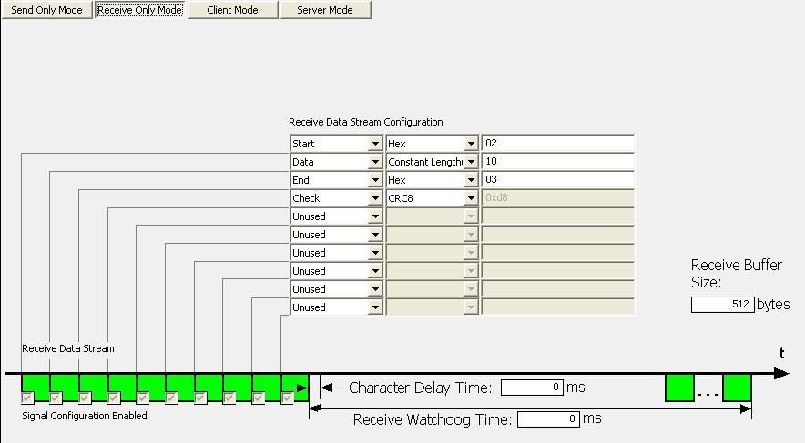
133 Configuration 133/172
134 Configuration 134/ Client Mode (First Send, Then Receive) In the 'Client Mode' the device sends a telegram to the remote device. The remote device then sends a telegram which is received by the device. By this a polling (querying) of the remote devices can be performed. The device can send a polling telegram with or without user data. The send operation can be triggered or performed cyclically. triggered With each handshake of the superordinated control unit a telegram is send. Setting the timing parameter Send Cycle Time to zero. The remote device then sends a telegram which is received by the device. The device can monitor the beginning of the receive telegram temporally via the Response Timeout parameter. The superordinated control unit must activate the send operation by handshake. The superordinated control unit must acknowledge each reception by handshake. Cyclic The device sends in a constant cycle. With each handshake of the host the send data initially are updated in the internal buffer and sent during the next sending cycle. Setting the timing parameter Send Cycle Time to the cycle time (unequal to zero). The remote device then sends a telegram which is received by the device. The device can monitor the beginning of the receive telegram temporally via the Response Timeout parameter. The superordinated control unit must activate the send data by handshake. The superordinated control unit must acknowledge each reception by handshake.
 specifies the cycle time of the send telegram. The value 0 specifies that the send telegram is triggered.")
135 Configuration 135/172 Parameter Description Range of Value Send Cycle Time Response Timeout Character Delay Time Specifies whether the telegram will be sent cyclically or triggered. The value (unequal to zero) specifies the cycle time of the send telegram. The value 0 specifies that the send telegram is triggered. Specifies whether the reception of the response telegram is monitored temporally. Thereby the remote device can be monitored. The time is taken from telegram end to telegram end. The value (unequal to zero) specifies in what time the remote device must have sent the response telegram. If the time is exceeded, then an error is reported to the host. The value 0 specifies that the reception of response telegrams is not monitored. Specifies whether the time between two characters during reception is monitored temporally. The value (unequal to zero) specifies in what time the remote device must have sent the next telegram. If the time is exceeded, then an error is reported to the host. The value 0 specifies that no monitoring is performed. Table 51: Timing Parameters for the Operating Mode 'Client Mode' Default: Default: Default: 0
136 Configuration 136/ Server Mode (First Receive, Then Send) In the 'Server Mode' the unit receives a telegram from the remote device. The device then sends a telegram to the remote device. When configuring the telegram structure the method is defined how the end of the telegram is detected: Character Length Time The superordinated control unit must acknowledge each reception by handshake. The superordinated control unit must activate by handshake the send operation. Parameter Description Range of Value Receive Watchdog Time Response Timeout Character Delay Time Specifies whether the reception of subsequent telegrams is monitored temporally. Thereby the remote device can be monitored. The time is taken from telegram end to telegram end. The value (unequal to zero) specifies in what time the remote device must have sent the next telegram. If the time is exceeded, then an error is reported to the host. The value 0 specifies that the reception of subsequent telegrams is not monitored. Specifies whether the reception of the response telegram is monitored temporally. Thereby the remote device can be monitored. The time is taken from telegram end to telegram end. The value (unequal to zero) specifies in what time the remote device must have sent the response telegram. If the time is exceeded, then an error is reported to the host. The value 0 specifies that the reception of response telegrams is not monitored. Specifies whether the time between two characters during reception is monitored temporally. The value (unequal to zero) specifies in what time the remote device must have sent the next telegram. If the time is exceeded, then an error is reported to the host. The value 0 specifies that no monitoring is performed. Table 52: Timing Parameters for the Operating Mode 'Server Mode' Default: Default: Default: 0

137 Configuration 137/ Settings for the ASCII Remote Device Note: The settings in the used remote device must comply with the settings in the nettap or netbrick device to establish a communication. Important parameters are: Interface type, baud rate, data bits, parity check and respectively RTS control.
138 Configuration 138/ Configuration Serial with netscript The nettap NT 100 device respectively the netbrick NB 100 device as serial with netscript needs parameter and beyond a script has to be created and loaded. These parameter can be edited as follows: 1. Open the configuration dialog Select from the context menu of the nettap respectively the netbrick symbol the entry Configuration > netscript The netscript settings dialog opens. In the navigation area the entry Settings under the folder Configuration is selected and the settings dialog is displayed. 2. netscript settings Select in the dialog window the interface type, RTS control, baudrate, number of data bits, number of stop bits and parity. The settings are described in the following section netscript Settings on page Signal configuration The signal configuration is done with default value automatically by SYCON.net software. 4. Close configuration dialog Click on OK to save the parameter or click on Cancel, if the parameter should not be saved. The configuration dialog closes Note: The programming of a script, loading the script into the nettap or netbrick device, the debugging of the script is described in detail in an own manual: netscript Programming Language for Serial Communication UM xx EN.pdf
139 Configuration 139/ netscript Settings Parameter Meaning Value Range/Value Interface type Type of the serial interface, which should be used RS232 (Default), RS485, RS422 RTS Control Specifies, if RTS control is activated or deactivated. When using the interface type RS-485, then "RTS Control on" has to be used. RTS Control Off (Default), RTS Control On Baud rate Specifies the baud rate. 300 Bit/s 600 Bit/s 1200 Bit/s 2400 Bit/s 4800 Bit/s 9600 Bit/s (Default) Bit/s Bit/s Bit/s Bit/s Data bits Specifies the number of data bits, 7 or 8 7, 8 (Default) Stop bits Specifies the number of stop bits, 1 or 2 1 (Default) 2 Parity Specifies the parity bit of the serial data communication. None means that no parity bit is used. Table 53: netscript Settings None (Default), Even, Odd Settings for the ASCII Remote Device Note: The settings in the used remote device must comply with the settings in the nettap or netbrick device to establish a communication. Important parameters are: Interface type, baud rate, data bits, parity check and respectively RTS control.
140 Configuration 140/ Signal Configuration At the pane Signal Configuration the data structure and the signal name of the in- and output signals is displayed. These signal are used for the signal mapping. Here for the single signals respectively the names of the signal names are set or the data types are configured. SYCON.net generates for the signal names default names. These names can be overwritten by the user. Parameter Meaning Range of Value/ Value Type Type of the input or output signals String Tag Signal name for the single input or output signals. The name can be set by the user. String Data type Data type of the single input or output signals. Depending by the used AS-Interface Slave profile the user can select the data type from a list. BIT, WORD, SIGNED16, UNSIGNED16, etc., Default: depends on the used protocol IO Type Input or output signal input, output Table 54: Explanations to the Dialog Pane Signal Configuration
141 Diagnosis 141/172 5 Diagnosis 5.1 Overview Diagnosis The dialog Diagnosis serves to diagnose the device behavior and communication errors. For diagnosis the device must reside in online state. The Extended Diagnosis helps to find communication and configuration errors, when default diagnosis fails. Diagnosis Panes The table below gives an overview for the individual Diagnosis dialog panes descriptions: Section Page General Diagnosis 142 Firmware Diagnosis 145 Table 55: Descriptions of the Diagnosis Panes Note: Accessing the Diagnosis panes of the netgateway DTM requires an online connection from the netgateway DTM to the nettap NT 100 device. For further information, refer to section Connecting/Disconnecting Device on page 146. Figure 27: Navigation Area - Diagnosis

142 Diagnosis 142/ General Diagnosis Information regarding the Device State and other general diagnosis parameters are displayed in the General Diagnosis dialog. Figure 28: General Diagnosis
143 Diagnosis 143/172 Indication Device State Communicating Meaning Communicating: Shows that the nettap firmware executes the network communication. Run Device is configured: Shows that the nettap firmware has been configured correctly. Ready Ready: Shows that the nettap firmware has been started correctly. The nettap firmware waits for a configuration. Error Network State Operate Error: Shows that the nettap firmware records a device status error. For further information to the error characteristics and the number of counted errors refer to the extended diagnosis. Operate: Shows that the nettap firmware is in data exchange. Idle Idle: Shows that the nettap firmware is in idle mode. Stop Offline Stop: Shows that the nettap firmware is in Stop state: There is no cyclic data exchange at the network. The nettap firmware was stopped by the application program or it changed to the Stop state because of a bus error. Offline: The nettap firmware is offline pending it does not have a valid configuration. Configuration State Configuration locked Configuration locked: Shows that the nettap firmware configuration is locked, to avoid the configuration data are typed over. New Configuration pending New Configuration pending: Shows that a new nettap firmware configuration is available. Reset required Reset required: Shows that a firmware reset is required as a new nettap firmware configuration has been loaded into the device. Bus ON Table 56: Indication General Diagnosis Bus ON: Shows whether the bus communication was started or stopped. I. e., whether the device is active on the bus or no bus communication to the device is possible and no response telegrams are sent.
144 Diagnosis 144/172 Parameter Communication Error Watchdog time Error Count Meaning Table 57: Parameter General Diagnosis Communication Error: Shows the message text of the communication error. If the cause of the current error is resolved, is displayed. Watchdog time: Shows the watchdog time in ms. Error Count: This field holds the total number of errors detected since power-up, respectively after reset. The protocol stack counts all sorts of errors in this field no matter if they were network related or caused internally.
 are indicated. Figure 29: Firmware Diagnosis (*The name of the Firmware is displayed.")
145 Diagnosis 145/ Firmware Diagnosis In the dialog Firmware Diagnosis the actual task information of the firmware is displayed. Under Firmware or Version the name of the firmware and version (including the date) are indicated. Figure 29: Firmware Diagnosis (*The name of the Firmware is displayed.) Task Information: The table Task Information is listing the task information of the single firmware tasks. Column Task Task Name Version Prio Description Status Meaning Task number Name of the task Version of the task Priority of the task Description of the task Status of the task Table 58: Description Table Task Information
Configuration of Gateway and Proxy Devices
 Operating Instruction Manual Configuration of Gateway and Proxy Devices nettap, netbrick and netlink Hilscher Gesellschaft für Systemautomation mbh www.hilscher.com DOC081201OI06EN Revision 6 English 2014-04
DTM for Hilscher DeviceNet Master Devices
 tgg Operating Instruction Manual DTM for Hilscher DeviceNet Master Devices Configuration of Hilscher Master Devices Hilscher Gesellschaft für Systemautomation mbh www.hilscher.com DOC070403OI12EN Revision
Generic Slave DTM for AS-Interface Slave Devices
 Operating Instruction Manual Generic Slave DTM for AS-Interface Slave Devices Configuration of AS-Interface Slave Devices Hilscher Gesellschaft für Systemautomation mbh www.hilscher.com DOC090604OI05EN
DTM for Hilscher CANopen Master Devices
 Operating Instruction Manual DTM for Hilscher CANopen Master Devices Configuration of Hilscher Master Devices Hilscher Gesellschaft für Systemautomation mbh www.hilscher.com DOC070402OI14EN Revision 14
DTM for Hilscher EtherCAT Master Device
 Operating Instruction Manual DTM for Hilscher EtherCAT Master Device Configuration of Hilscher Master Devices Hilscher Gesellschaft für Systemautomation mbh www.hilscher.com DOC080404OI07EN Revision 7
DTM for EtherNet/IP Adapter Devices
 Operating Instruction Manual DTM for EtherNet/IP Adapter Devices Configuration of EtherNet/IP Adapter Devices Hilscher Gesellschaft für Systemautomation mbh www.hilscher.com DOC061202OI09EN Revision 9
Generic Slave DTM for sercos Slave Devices
 Operating Instruction Manual Generic Slave DTM for sercos Slave Devices Configuration of sercos Slave Devices Hilscher Gesellschaft für Systemautomation mbh www.hilscher.com DOC090302UM06EN Revision 6
Operating Instruction Manual SyConDN System Configurator DeviceNet Hilscher Gesellschaft für Systemautomation mbh
 Operating Instruction Manual SyConDN System Configurator DeviceNet Hilscher Gesellschaft für Systemautomation mbh www.hilscher.com DOC980304OI10EN Revision 10 English 2012-06 Released Public Overview SyCon
nettap NT 100 User Manual Gateway Devices Hilscher Gesellschaft für Systemautomation mbh
 User Manual nettap NT 100 Gateway Devices Hilscher Gesellschaft für Systemautomation mbh www.hilscher.com DOC081001UM18EN Revision 18 English 2015-01 Released Public Table of Contents 2/135 Table of Contents
Configuration of LAN Controlled Master Devices
 Operating Instruction Manual Configuration of LAN Controlled Master Devices nethost Hilscher Gesellschaft für Systemautomation mbh www.hilscher.com DOC130402OI04EN Revision 4 English 2015-07 Released Public
CANopen Slave. Protocol API V Hilscher Gesellschaft für Systemautomation mbh
 Protocol API CANopen Slave V3.7.0 Hilscher Gesellschaft für Systemautomation mbh www.hilscher.com DOC111001API06EN Revision 6 English 2016-07 Released Public Table of Contents 2/151 Table of Contents 1
Generic Slave DTM for CANopen Slave Devices
 Operating Instruction Manual Generic Slave DTM for CANopen Slave Devices Configuration of CANopen Slave Devices Hilscher Gesellschaft für Systemautomation mbh www.hilscher.com DOC060203OI06EN Revision
EtherCAT Master V3. Protocol API. V3.0.x.x. Hilscher Gesellschaft für Systemautomation mbh
 Protocol API EtherCAT Master V3 V3.0.x.x Hilscher Gesellschaft für Systemautomation mbh www.hilscher.com DOC110506API05EN Revision 5 English 2013-05 Released Public Introduction 2/150 Revision History
cifx Device Driver Driver Manual WinAC RTX 2010 Hilscher Gesellschaft für Systemautomation mbh
 Driver Manual cifx Device Driver WinAC RTX 2010 Hilscher Gesellschaft für Systemautomation mbh www.hilscher.com DOC140702DRV02EN Revision 2 English 2014-12 Released Public Introduction 2/84 Table of Contents
nettap NT 100 User Manual Gateway Devices Hilscher Gesellschaft für Systemautomation mbh
 a User Manual nettap NT 100 Gateway Devices Hilscher Gesellschaft für Systemautomation mbh www.hilscher.com DOC081001UM07EN Revision 7 English 2010-09 Released Public Inhaltsverzeichnis 2/113 Table of
User Manual CIFX Cards Real Time Ethernet
 User Manual CIFX Cards Real Time Ethernet Installation, Operation and Hardware Description Language: English www.hilscher.com Communication Interface Hilscher cifx-re Table of Contents 2 Table of Contents
netanalyzer Software Operation Instruction Manual Installation and Use of the Analysis Software
 Operation Instruction Manual netanalyzer Software Installation and Use of the Analysis Software Hilscher Gesellschaft für Systemautomation mbh www.hilscher.com DOC150304OI01EN Revision 1 English 2015-04
Software Installation and Documentation Overview
 Installation Software Installation and Documentation Overview Communication Solutions Hilscher Gesellschaft für Systemautomation mbh www.hilscher.com DOC110907IG04EN Revision 4 English 2013-12 In Development
netbrick NB 100 User Manual Gateway Devices Hilscher Gesellschaft für Systemautomation mbh
 User Manual netbrick NB 100 Gateway Devices Hilscher Gesellschaft für Systemautomation mbh www.hilscher.com DOC091111UM12EN Revision 12 English 2014-03 Released Public Introduction 2/122 Table of Contents
netscope Operating Instruction Manual Instrument Driver for LabVIEW Hilscher Gesellschaft für Systemautomation mbh
 Operating Instruction Manual netscope Instrument Driver for LabVIEW Hilscher Gesellschaft für Systemautomation mbh www.hilscher.com DOC131005OI01EN Revision 1 English 2013-11 In Development Internal Table
Serial Dual-Port Memory Interface with netx
 Getting Started Guide Serial Dual-Port Memory Interface with netx Hilscher Gesellschaft für Systemautomation mbh www.hilscher.com DOC120210GS04EN Revision 4 English 2015-04 Released Public Introduction
cifx Device Driver Driver Manual cifx Device Driver under CeWin V Hilscher Gesellschaft für Systemautomation mbh
 Driver Manual cifx Device Driver cifx Device Driver under CeWin V1.0.1.0 Hilscher Gesellschaft für Systemautomation mbh www.hilscher.com DOC110502DRV02EN Revision 2 English 2012-04 Released Public Introduction
What's New netjack. Revision List. Communication Solutions DVD Hilscher Gesellschaft für Systemautomation mbh
 Revision List What's New netjack Communication Solutions DVD 2014-08-1 Hilscher Gesellschaft für Systemautomation mbh www.hilscher.com DOC120707RL03EN Revision 3 English 2014-08 Released Public Introduction
Dual-Port Memory Interface
 Dual-Port Memory Interface Manual Dual-Port Memory Interface netx based Products Hilscher Gesellschaft für Systemautomation mbh www.hilscher.com DOC060302DPM12EN Revision 12 English 2012-03 Released Public
DeviceNet Master. Protocol API. V2.3.x.x. Hilscher Gesellschaft für Systemautomation mbh
 Protocol API DeviceNet Master V2.3.x.x Hilscher Gesellschaft für Systemautomation mbh www.hilscher.com DOC080301API10EN Revision 10 English 2013-09 Released Public Table of Contents 2/167 Table of Contents
Ethernet Modbus X80 Gateway Device Type Manager
 Ethernet Modbus X80 Gateway Device Type Manager EIO0000001315 10/2012 Ethernet Modbus X80 Gateway Device Type Manager User Manual 10/2012 EIO0000001315.00 www.schneider-electric.com The information provided
VARAN Client (Slave) Protocol API. V1.0.x.x. Hilscher Gesellschaft für Systemautomation mbh
 Protocol API. V1.0.x.x. Hilscher Gesellschaft für Systemautomation mbh") Protocol API VARAN Client (Slave) V1.0.x.x Hilscher Gesellschaft für Systemautomation mbh www.hilscher.com DOC100613API03EN Revision 3 English 2013-10 Released Public Table of Contents 2/67 Table of Contents
Protocol API VARAN Client (Slave) V1.0.x.x Hilscher Gesellschaft für Systemautomation mbh www.hilscher.com DOC100613API03EN Revision 3 English 2013-10 Released Public Table of Contents 2/67 Table of Contents
Drive System Application
 Drive System Application Application Description Uploading and downloading drive parameters of a xx using STARTER Table of Contents Table of Contents 1 Warranty, liability and support... 3 2 Description...
MULTIFUNCTIONAL DIGITAL SYSTEMS. Software Installation Guide
 MULTIFUNCTIONAL DIGITAL SYSTEMS Software Installation Guide 2013 TOSHIBA TEC CORPORATION All rights reserved Under the copyright laws, this manual cannot be reproduced in any form without prior written
DeviceNet Master. Protocol API V Hilscher Gesellschaft für Systemautomation mbh
 Protocol API DeviceNet Master V2.4.0 Hilscher Gesellschaft für Systemautomation mbh www.hilscher.com DOC080301API11EN Revision 11 English 2016-06 Released Public Table of Contents 2/180 Table of Contents
SIMATIC. Component Based Automation SIMATIC imap STEP 7 AddOn Creating PROFINET components. Preface. Creating PROFINET components in STEP 7
 SIMATIC Component Based Automation SIMATIC Component Based Automation SIMATIC imap STEP 7 AddOn Creating PROFINET components Configuration Manual Preface Creating PROFINET components in STEP 7 1 SIMATIC
Getting Started - Startdrive. Startdrive SINAMICS. Introduction 1. Connecting the drive unit to the PC. Creating a project 3
 Getting Started - Startdrive Introduction 1 Connecting the drive unit to the PC 2 Startdrive SINAMICS Getting Started Creating a project 3 Going online and incorporating devices 4 Commissioning the drive
MULTIFUNCTIONAL DIGITAL SYSTEMS. Software Installation Guide
 MULTIFUNCTIONAL DIGITAL SYSTEMS Software Installation Guide 2013 TOSHIBA TEC CORPORATION All rights reserved Under the copyright laws, this manual cannot be reproduced in any form without prior written
How to Configure DeviceNet with Anybus Configuration Manager (ACM) for DeviceNet APPLICATION NOTE DRAFT
 for DeviceNet APPLICATION NOTE DRAFT") How to Configure DeviceNet with Anybus Configuration Manager (ACM) for DeviceNet APPLICATION NOTE ENGLISH Important User Information Liability Every care has been taken in the preparation of this document.
How to Configure DeviceNet with Anybus Configuration Manager (ACM) for DeviceNet APPLICATION NOTE ENGLISH Important User Information Liability Every care has been taken in the preparation of this document.
EtherCAT Slave. Protocol API V Hilscher Gesellschaft für Systemautomation mbh
 Protocol API EtherCAT Slave V4.7.0 Hilscher Gesellschaft für Systemautomation mbh www.hilscher.com DOC110909API10EN Revision 10 English 2017-10 Released Public Table of contents 2/207 Table of contents
User Manual Gateway component for EtherNet/IP
 User Manual Gateway component for EtherNet/IP PR100066 1/7/2016 Table of Contents KUNBUS GmbH Table of Contents 1 General Information... 3 1.1 Disclaimer... 3 1.2 Notes Regarding this User Manual... 4
 Multiuser Engineering in the TIA Portal TIA Portal V15 https://support.industry.siemens.com/cs/ww/en/view/109740141 Siemens Industry Online Support Warranty and Liability Warranty and Liability The Application
netx DPM Interface Manual DPM Interface Manual for netx based Products Language: English
 netx DPM Interface Manual DPM Interface Manual for netx based Products Language: English www.hilscher.com netx DPM Interface Introduction 2 Rev Date Name Revisions 0 3-Mar-06 rm, tk created 1 13-Jun-06
Welcome to the Future of Industrial Communication. Introducing the netx Family of Controllers by Hilscher
 Welcome to the Future of Industrial Communication Introducing the netx Family of Controllers by Hilscher netx: ONE CONTROLLER FOR EVERY NETWORK THE FUTURE OF AUTOMATION WILL CENTER ON YOUR ABILITY TO OPTIMIZE
Schneider Electric Floating License Manager
 Schneider Electric Floating License Manager EIO0000001078 11/2012 Schneider Electric Floating License Manager User Manual 12/2012 EIO0000001078.01 www.schneider-electric.com The information provided in
Applications & Tools. SINAMICS G/S: Commissioningsupport scripts for SINAMICS drives. SINAMICS commissioning auxiliary scripts
 SINAMICS G/S: Commissioningsupport scripts for SINAMICS drives Application description July 2013 Applications & Tools Answers for industry. Siemens Industry Online Support This article originates from
Device Programming using TRWinProg
 Device Programming using TRWinProg Software No.: _490-00416 _490-00416_WIN7 _Program Summary _Safety instructions _System requirements _Program installation _Connecting devices to the PC _Program start
DT9000 Development Kit V1.1
 DT9000 Development Kit V1.1 Diamond Technologies Getting data where it needs to be. 6 Clock Tower Place Suite 100 Maynard, MA 01754 USA Tel: (866) 837 1931 Tel: (978) 461 1140 FAX: (978) 461 1146 http://www.diamondt.com/
Addendum to the Manual
 Drive Technology \ Drive Automation \ System Integration \ Services *23074914_0117* Addendum to the Manual MOVIFIT Device Replacement Function Edition 01/2017 23074914/EN SEW-EURODRIVE Driving the world
Servo press kit YJKP - Host interface
 Application Note Servo press kit YJKP - Host interface Host interface of the servo press kit YJKP: - Communication possibilities - Workflow - Object directory - Communication protocol - Communication Mobus
Drive Technology \ Drive Automation \ System Integration \ Services. Manual. MOVIFIT SNI UFF41B/UFR41B Fieldbus Gateway for MOVIGEAR SNI
 Drive Technology \ Drive Automation \ System Integration \ Services Manual MOVIFIT SNI UFF41B/UFR41B Fieldbus Gateway for MOVIGEAR SNI Edition 0/2010 1694641 / EN SEW-EURODRIVE Driving the world 1 General
FBP FieldBusPlug. Technical Manual. USB to FBP UTF21-FBP UTF21-FBP DTM V
 FBP FieldBusPlug V6 USB to FBP 1SAJ 929 499 R0001 F ABB STOTZ-KONTAKT GmbH 03/2010 DTM V2.0.3 www.abb.de/stotz-kontakt V 6 Please note the following Target group This description is intended for the use
USB Memory Drive CD with Application Software and Drivers for Windows 98SE. 32 MB, > 64 MB recommended. min. 2x (for probable installation)
") User Manual USB Memory Drive Content: Included with USB Memory Drive...1 System Requirements...1 Warranty...2 Making Copies of This Manual...2 Notes on this Manual...3 Data Security...3 Operational Safety...3
User Manual USB Memory Drive Content: Included with USB Memory Drive...1 System Requirements...1 Warranty...2 Making Copies of This Manual...2 Notes on this Manual...3 Data Security...3 Operational Safety...3
Multiuser Engineering in the TIA Portal
 Application Example 02/2017 Multiuser Engineering in the TIA Portal TIA Portal V14 https://support.industry.siemens.com/cs/ww/de/view/109740141 Warranty and Liability Warranty and Liability The Application
COMMERCIAL BANK OF DUBAI PSC GENERAL CONDITIONS OF ACCESS AND USE OF COMMERCIAL BANK OF DUBAI FACEBOOK BRANCH
 COMMERCIAL BANK OF DUBAI PSC GENERAL CONDITIONS OF ACCESS AND USE OF COMMERCIAL BANK OF DUBAI FACEBOOK BRANCH 1. CBD Facebook Branch Commercial Bank of Dubai psc (hereinafter "CBD"), allows access and
Application for Process Automation
 Application for Process Automation Connecting external periphery to PCS 7 via IE/PB Link PN IO Application Note Warranty, liability and support Note The Application Examples are not binding and do not
S7A Driver / OPC Server. Hilscher CIFX-RE interface. PROFINET I/O Device (Slave)
") Application Note for S7A Driver / OPC Server connecting to a Hilscher CIFX-RE interface as PROFINET I/O Device (Slave) Date: 05.04.2016 Author: J. Stähler, InCoSol-Industrial Communications Solutions Draft
Application Note for S7A Driver / OPC Server connecting to a Hilscher CIFX-RE interface as PROFINET I/O Device (Slave) Date: 05.04.2016 Author: J. Stähler, InCoSol-Industrial Communications Solutions Draft
Communication between HMI and Frequency Converter. Basic Panel, Comfort Panel, Runtime Advanced, SINAMICS G120. Application Example 04/2016
 Application Example 04/2016 Communication between HMI and Frequency Converter Basic Panel, Comfort Panel, Runtime Advanced, SINAMICS G120 https://support.industry.siemens.com/cs/ww/en/view/109481157 Warranty
S900 I/O DTM 6.x. System Version 6.0. Power and productivity for a better world TM
 S900 I/O DTM 6.x System Version 6.0 Power and productivity for a better world TM S900 I/O DTM 6.x NOTICE This document contains information about one or more ABB products and may include a description
Setting up a secure VPN Connection between two M812-1 Using a static IP Address
 Configuration Example 07/2015 Setting up a secure VPN Connection between two M812-1 Using a static IP Address SCALANCE M https://support.industry.siemens.com/cs/ww/en/view/109477919 Warranty and Liability
Thermo Scientific. Centri-Log V1.0. Operating Manual November 2010
 Thermo Scientific Centri-Log V1.0 Operating Manual 50127006-1 November 2010 2010 Thermo Fisher Scientific Inc. All rights reserved. RC 3BP+ TM, RC 12BP+ TM and RC BIOS are either registered trademarks
Drive Technology \ Drive Automation \ System Integration \ Services. Manual. MOVIFIT SNI Fieldbus Gateway UFF41B for MOVIGEAR SNI
 Drive Technology \ Drive Automation \ System Integration \ Services Manual MOVIFIT SNI Fieldbus Gateway UFF41B for MOVIGEAR SNI Edition 05/2009 16810414 / EN SEW-EURODRIVE Driving the world 1 General Information...
Production feedback via WinCC Data Transfer with XML file
 Application Example 09/2016 Production feedback via WinCC Data Transfer with XML file WinCC/IndustrialDataBridge V7.4, SIMATIC WinCC V7 https://support.industry.siemens.com/cs/ww/en/view/109483465 Warranty
USB Server User Manual
 1 Copyright Notice Copyright Incorporated 2009. All rights reserved. Disclaimer Incorporated shall not be liable for technical or editorial errors or omissions contained herein; nor for incidental or consequential
Asset Management Migration Guide
 www.novell.com/documentation Asset Management Migration Guide ZENworks 11 Support Pack 2 March 20, 2012 Legal Notices Novell, Inc., makes no representations or warranties with respect to the contents or
Instruction Manual. AP-SoftPrint. Multiwave 3000/ Multiwave ECO and Synthos 3000 Software v2.5
 Instruction Manual AP-SoftPrint Multiwave 3000/ Multiwave ECO and Synthos 3000 Software v2.5 Instruction Manual AP-SoftPrint Multiwave 3000/ Multiwave ECO and Synthos 3000 Software v2.5 Anton Paar GmbH
Expense Management Asset Management
 Expense Management Asset Management User Guide NEC NEC Corporation November 2010 NDA-31136, Revision 1 Liability Disclaimer NEC Corporation reserves the right to change the specifications, functions, or
nettap NT 151 RE RE User manual Real Time Ethernet gateway Hilscher Gesellschaft für Systemautomation mbh
 User manual nettap NT 151 RE RE Real Time Ethernet gateway Hilscher Gesellschaft für Systemautomation mbh www.hilscher.com Table of contents 2/81 Table of contents 1 Introduction... 4 1.1 About this document...
Application Note. a HART Tool-routing with Emerson AMS HART over TH LINK PROFIBUS for Asset Management 1.0.0
 Application Note a116110 HART over TH LINK PROFIBUS for Asset Management 2 Application Note a116110 2016 by WAGO Kontakttechnik GmbH & Co. KG All rights reserved. WAGO Kontakttechnik GmbH & Co. KG Hansastraße
Applications & Tools. Configuration of Direct Starters with the APL Channel Block FbSwtMMS in SIMATIC PCS 7 SIMATIC PCS 7 V8.0
 Cover with the APL Channel Block FbSwtMMS in SIMATIC PCS 7 SIMATIC PCS 7 V8.0 Application Example October 2012 Applications & Tools Answers for industry. Siemens Industry Online Support This document is
Supplementary device manual EtherCAT interface in the AS-i controllere A AC1391 AC1392
 Supplementary device manual EtherCAT interface in the AS-i controllere A AC1391 AC139 firmware version RTS.x target from 15 for CoDeSys from version.3 English 739071_00_UK 01-0- Contents Revision: 16 December
SICAM SICAM FCM Configurator
 Preface Open Source Software SICAM SICAM FCM Configurator Table of Contents SICAM FCM Configurator 1 Index V02.10 Configuration and Operation E50417-H8940-C592-A3 i NOTE For your own safety, observe the
PROFIsafe modules V2 ipar 75x-66x/ WAGO Safety-Editor-75x Quickstart
 PROFIsafe modules V2 ipar 75x-66x/000-003 WAGO Safety-Editor-75x Quickstart Version 06.00.00 2 General Copyright 2010 by WAGO Kontakttechnik GmbH & Co. KG All rights reserved. WAGO Kontakttechnik GmbH
AWLaunch. Software Manual. Version 1.2 Last Revised April 27, 2009
 AWLaunch Software Manual Version 1.2 Last Revised April 27, 2009 All contents in this manual are copyrighted by ArWest Communications. All rights reserved.the information contained herein may not be used,
EtherCAT Master V4. Protocol API V4.2. Hilscher Gesellschaft für Systemautomation mbh
 Protocol API EtherCAT Master V4 V4.2 Hilscher Gesellschaft für Systemautomation mbh www.hilscher.com DOC150601API02EN Revision 2 English 2015-11 Preliminary Public Introduction 2/240 Table of Contents
PC Cards cifx PC/104 (CIFX 104)
") User Manual PC Cards cifx PC/104 (CIFX 104) Installation, Operation and Hardware Description Hilscher Gesellschaft für Systemautomation mbh www.hilscher.com DOC120206UM46EN Revision 46 English 2015-12
User Manual PC Cards cifx PC/104 (CIFX 104) Installation, Operation and Hardware Description Hilscher Gesellschaft für Systemautomation mbh www.hilscher.com DOC120206UM46EN Revision 46 English 2015-12
User manual Gateway component Sercos
 User manual Gateway component Sercos DO0227R00 6/28/2016 Table of Contents KUNBUS GmbH Table of Contents 1 General Information... 3 1.1 Disclaimer... 3 1.2 Notes Regarding this User Manual... 3 1.3 Validity...
Operation. English. Detection And Evaluation Of Licence Numbers. SEDOR ANPR Server. Rev /
 Operation English Detection And Evaluation Of Licence Numbers SEDOR ANPR Server Rev. 1.0.0 / 2015-03-25 Information about copyright, trademarks, design patents 2015 Dallmeier electronic The reproduction,
SIMATIC/SINAMICS. Getting started with SINAMICS V90 PN on S Motion Control. Fundamental safety instructions 1. Introduction
 Fundamental safety instructions 1 Introduction 2 SIMATIC/SINAMICS Getting started with SINAMICS V90 PN on S7-1500 Motion Control Getting Started Prepare the configuration 3 Create a project 4 Creating
Software WINDY BOY Setup Tool
 Software WINDY BOY Setup Tool User Manual WBSetup-BEN100411 Version 1.1 EN Table of Contents Table of Contents 1 Notes on this Manual.............................. 5 1.1 Area of Validity......................................
 Safety-Related IO Controller-I-Device Communication SIMATIC, PROFIsafe https://support.industry.siemens.com/cs/ww/en/view/109478798 Siemens Industry Online Support Legal information Legal information Use
sercos Master Protocol API V2.1.x.x Hilscher Gesellschaft für Systemautomation mbh
 Protocol API sercos Master V2.1.x.x Hilscher Gesellschaft für Systemautomation mbh www.hilscher.com DOC081103API11EN Revision 11 English 2013-09 Released Public Table of Contents 2/390 Table of Contents
Applications & Tools. Service Concept: Auto Backup for the Comfort Panels. WinCC (TIA Portal) V12. Application Description May 2013
 V12. Application Description May 2013") Cover Service Concept: Auto Backup for the Comfort Panels WinCC (TIA Portal) V12 Application Description May 2013 Applications & Tools Answers for industry. Copyright Siemens AG 2013 All rights reserved
Cover Service Concept: Auto Backup for the Comfort Panels WinCC (TIA Portal) V12 Application Description May 2013 Applications & Tools Answers for industry. Copyright Siemens AG 2013 All rights reserved
Installing Your Microsoft Access Database (Manual Installation Instructions)
") Installing Your Microsoft Access Database (Manual Installation Instructions) Installation and Setup Instructions... 1 Single User Setup... 1 Multiple User Setup... 2 Adjusting Microsoft Access 2003 Macro
Installing Your Microsoft Access Database (Manual Installation Instructions) Installation and Setup Instructions... 1 Single User Setup... 1 Multiple User Setup... 2 Adjusting Microsoft Access 2003 Macro
eloprog 485EPF.. - Vers. 1.2 eloprog Configurable safety system FIELD BUS MODULES
 eloprog 485EPF.. - Vers. 1.2 eloprog Configurable safety system FIELD BUS MODULES 1 List of contents INTRODUCTION 3 ELECTRICAL CONNECTIONS 3 PROTOCOL DATA PACKAGE COMPOSITION 4 DIAGNOSTICS 6 The "I/O index"
I-Device Function in Standard PN Communication SIMATIC S7-CPU, CP, SIMOTION, SINUMERIK. Configuration Example 08/2015
 Configuration Example 08/2015 Function in Standard PN Communication SIMATIC S7-CPU, CP, SIMOTION, SINUMERIK https://support.industry.siemens.com/cs/ww/en/view/109478798 Siemens AG 2015 All rights reserved
Schneider Electric License Manager
 Schneider Electric License Manager EIO0000001070 11/2012 Schneider Electric License Manager User Manual 12/2012 EIO0000001070.01 www.schneider-electric.com The information provided in this documentation
Configuration of an MRP Ring and a Topology with Two Projects
 Configuration Example 10/2016 Configuration of an MRP Ring and a Topology with Two Projects SCALANCE X, SIMATIC S7 https://support.industry.siemens.com/cs/ww/en/view/109741671 Warranty and Liability Warranty
Modbus RTU Protocol description
 Modbus RTU Protocol description English (translation of original instructions) Documentation no.: 4102219 Imprint Imprint Publisher and responsible for the content: HYDAC FILTER SYSTEMS GMBH Postfach 1251
User Manual Revision English
 Document code: MN67562_ENG Revision 1.005 Page 1 of 14 User Manual Revision 1.005 English PROFIBUS Slave / Modbus Slave - Converter (Order Code: HD67562) for Website information: www.adfweb.com?product=hd67562
User Manual Revision English
 Document code: MN67251_ENG Revision 1.001 Page 1 of 18 User Manual Revision 1.001 English NMEA 2000 / DeviceNet - Converter (Order Code: HD67251-A1 - HD67251-A3 - HD67251-A4) for Website information: www.adfweb.com?product=hd67251-a1
SINAMICS G/S: Tool for transforming Warning and Error Messages in CSV format
 Application example 03/2017 SINAMICS G/S: Tool for transforming Warning and Error Messages in CSV format https://support.industry.siemens.com/cs/ww/en/view/77467239 Copyright Siemens AG 2017 All rights
TA Instrument Explorer. Getting Started Guide
 TA Instrument Explorer Getting Started Guide Revision A Issued May 2005 2005 by TA Instruments 109 Lukens Drive New Castle, DE 19720 Notice The material contained in this manual, and in the online help
Industrial Controls. Motor management and control devices SIMOCODE pro. Introduction 1. Configuring a reversing starter. List of abbreviations
 Introduction 1 Configuring a reversing starter 2 Industrial Controls A List of abbreviations Motor management and control devices Getting Started 05/2018 A5E40507294002A/RS-AB/002 Legal information Warning
DME-N Network Driver Installation Guide for M7CL
 DME-N Network Driver Installation Guide for M7CL ATTENTION SOFTWARE LICENSE AGREEMENT PLEASE READ THIS SOFTWARE LICENSE AGREEMENT ( AGREEMENT ) CAREFULLY BEFORE USING THIS SOFTWARE. YOU ARE ONLY PERMITTED
Tool Calling Interface
 Tool Calling Interface TCI2Com for RS4 and COMPACTplus User s Guide 600669 2009/02 Subject to change without prior notice About the User s Guide The User's Guide contains information on the use and application
SIMATIC. SIMATIC Logon V User management and electronic signatures 1. Hardware and Software Requirements 2. Scope of delivery 3.
 User management and electronic signatures 1 Hardware and Software Requirements 2 SIMATIC Scope of delivery 3 Installation 4 SIMATIC Logon 5 Configuration Manual 12/2015 A5E34528136-AA Legal information
Universal Parameter Server
 Library Description 10/2015 Universal Parameter Server SIMATIC S7-1500 https://support.industry.siemens.com/cs/ww/en/view/45841087 Warranty and Liability Warranty and Liability Note The Application Examples
Firstly, to perform the following actions, you must have Admin Rights on your PC.
 Product: Checkbox IMH Subject: USB Drivers (Windows XP) The USB connection between a Checkbox IMH and a PC is not automatically recognised by Microsoft Windows and often results in the USB drivers not
SIMATIC. STEP 7 PLUS TIA Portal Teamcenter Gateway. Introduction to TIA Portal Teamcenter Gateway 1. System requirements 2
 Introduction to TIA Portal Teamcenter Gateway 1 System requirements 2 SIMATIC STEP 7 PLUS Basics of working with TIA Portal Teamcenter Gateway 3 Notes on the installation sequence for the TIA Portal and
Industrial-Automation System HIMatrix. MODBUS Master/Slave. Manual
 Industrial-Automation System HIMatrix MODBUS Master/Slave Manual HIMA Paul Hildebrandt GmbH + Co KG Rev. 0.02 Industrial Automation HI 800 003 HEA Important Notes All HIMA products mentioned in this manual
Generic HART DTM for FDT 1.2 compliant Frame Applications Release 4
 Generic HART DTM for FDT 1.2 compliant Frame Applications Release 4 Copyright ICS Industrielle Computer Systeme GmbH 2007, all rights reserved. Sublicense for brand labeled version granted to Microflex,
File Management Utility User Guide
 File Management Utility User Guide Legal Notes Unauthorized reproduction of all or part of this guide is prohibited. The information in this guide is subject to change without notice. We cannot be held
imagerunner 2545i/ i/ / Remote UI Guide
 Remote UI Guide Please read this guide before operating this product. After you finish reading this guide, store it in a safe place for future reference. ENG imagerunner 2545i/2545 2535i/2535 2530/2525
ADN. System Installer. Instruction manual
 ADN System Installer Instruction manual Content Content Installation requirements... 4 Selecting updates... 4 ADN System Update... 5 Establishing the connection... 5 Overview of the update stage window...