Survey and Alignment of the ILC An introduction to the concept and open questions
|
|
|
- Winfred Sharp
- 5 years ago
- Views:
Transcription


1 Survey and Alignment of the ILC An introduction to the concept and open questions Johannes Prenting, DESY, Survey & alignment, for the LiCAS collaboration Warsaw University LiCAS Applied Geodesy Group Linear Collider Alignment & Survey ILC Workshop Snowmass, Colorado, August 2005


2 LC Survey Challenge Survey = multi step process with single tolerance budget driven by accelerator physics: component construction component fiducialisation component survey machine alignment Components Survey: 200µm vertical, 500µm horizontal = our slice of tolerance budget over some 100m = O (betatron) wavelenght
3 possible survey solution for XFEL ILC Linac: Accuracy demands: accuracy requirements met? yes economic requirements met? yes survey solution found transversal : s module =0.5mm, s cavity =s quad =0.3mm, s BPM = 0.3mm vertical : s solution module =0.2mm, s cavity =s quad =0.2mm, s BPM = 0.2mm no unusable over a range of some 100m length. Injector:?? damping rings:?? beam delivery solution system:?? no unusable final focus:?? machine detector interface:?? What can we achieve with classical survey methods?
4 Achievable accuracy with conventional methods in this application mainly depends on the angle of refraction Pz κ δ[ rad ] = D s ds R D ( ) Ps mit δn δy = a = konstant n = refractive index κ = local refractive coefficient δt δy δt δy κ = f(p,t, ) f( ) approximation equations thus 2δ δ δn ds δy δn ds δy [ rad ] [ rad ] = P P z s = a D = D 2 0 and z = a 2 D 8
5 Numerical examples for various δt δy lateral Seitenrefraktion refraction δ T = +0, K δy 1 m Vergleich Höhenmessung Comparison with altimetry δ T = 0, K δy 065 m Entfernung distance Richtungsfehler angular error Querabweichung lateral error Richtungsfehler angular error Querabweichung lateral error [m] [mgon] [mm] [mgon] [mm] 50 0,16 0,031-0,10-0, ,32 0,125-0,21-0, ,48 0,281-0,31-0, ,64 0,500-0,41-0, ,80 0,781-0,52-0, ,95 1,125-0,62-0, ,91 4,500-1,24-2, ,82 18,000-2,48-11,700 Standard solution to minimize effects of refraction: monitoring pillars alternating on either side of the tunnel. Conventional optical method not suitable here.
6 LC Survey Challenge Complex & irregular layout of machine: Horizontally and vertically curved sections, (R min >500m) Some sections geometrically straight, others following geoid Sections with significant slopes Many different sections (Linac, DR, BDS, FF, MDI) Possibly various beamlines in one tunnel Temp. & pressure gradients in tunnel Very tight working space (1m wide) Space serves as emergency escape route Best solution is to split up the survey procedure into a reference survey (along the tunnel) and a stake out transfers coordinates to the machine over short distances across the tunnel Optical Survey methods are not precise enough for reference structure Need new instrument RTRS (Rapid Tunnel Reference Surveyor) Provides regular reference structure Uses regular markers at tunnel wall No long-term stable (>months) reference monuments at O(10 μm) level Need frequent surveys Need automated process

7 Straightness measurements with RTRS (multipoint alignment) A technique to avoid the effects of refraction is given by the multi-point alignment. This method replaces angle measurements by distance measurements to at least three points. target mark T u n n e l w a l l Detailed view T u n n e l w a l l target marks A moveable bar serves as a fundamental structure for straightness measurements. From this straight line the distances a to target marks at the tunnel wall are determined. To enhance redundancy the number of target marks observed can be increased.
8 RTRS concept wall markers internal FSI SM beam external FSI Tunnel Wall Reconstructed tunnel shapes (relative co-ordinates) carriage with LT or Theo. rail machine component


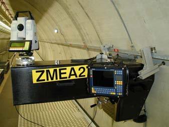
9 Stake out and alignment in the VUV-FEL DESY Stake out and alignment with Theodolite Stake out and alignment with Laser Tracker

10 RTRS: single car prototype (from 6 car train, DESY Version, (GeLiS))

11 RTRS prototype (LiCAS Version) Is going to be built as a 3-car prototype A 3-car prototype allows measurements of a traverse along a tunnel wall Most parts are at hand, assembly can start by september Test DESY is ready for installation
12 possible survey solution for XFEL ILC Linac: Accuracy demands: accuracy requirements met? yes transversal : s module =0.5mm, s cavity =s quad =0.3mm, s BPM = 0.3mm vertical : s solution module =0.2mm, s cavity =s quad =0.2mm, s BPM = 0.2mm no over a range unusable of some 100m length. LiCAS: ~40µm transversal, ~100µm vertical -> see talk of G.Grzelak economic requirements met? no solution unusable yes survey solution found
13 Cost calculation (of reference system) TCO Ref = R acc n surv L acc T sd (k sd + C surv ) + I surv + M surv R acc : Lifetime of accelerator [years] n surv : Number of surveys per year [1/year] L acc : Length of accelerator [km] T sd : SD-time required for 1 km survey [days/km] k sd : cost per shutdowntime [ /day] C surv : cost of survey team(s) [ /day] I surv : Investment costs for survey system [ ] M surv : Maintenance costs for Survey instruments [ ]
14 Cost calculation (conventional optical survey w. Lasertracker, 3 teams) R acc : 20 years n surv : 1.2 / year L acc : 33 km T sd : 5 days/km k sd : / day C surv : / day I surv : / team M surv : /instr./year TCO Ref = 1.1 Bill years downtime
15 Cost calculation (conventional optical survey w. Lasertracker, 10 teams) TCO Ref = 322 Mill years downtime Cost calculation (RTRS, 1 train) TCO Ref = 0.8 Mill years shutdown Costs include development!
16 possible survey solution for XFEL ILC Linac: Accuracy demands: accuracy requirements met? yes transversal : s module =0.5mm, s cavity =s quad =0.3mm, s BPM = 0.3mm vertical : s solution module =0.2mm, s cavity =s quad =0.2mm, s BPM = 0.2mm no over a range unusable of some 100m length. LiCAS: ~40µm transversal, ~100µm vertical -> see talk of G.Grzelak economic requirements met? no solution unusable Economic requirements: yes RTRS survey solution found
17 LiCAS pre CDR Working Document During this workshop we want to start writing a working document intended to be the precursor to a survey and alignment CDR section. We think this document could be divided like this: Definition of scope Overall survey and alignment strategy Overall cost estimates one chapter for each collider section that needs survey and alignment (sources, DR, Linac, BDS, FF, MDI, detector, polarimeters, etc.) Overall List of open R&D issues and who could work on them For each such collider-section specific chapter we intend to provide Requirements tolerances frequency/period Assumptions build tolerances beam based method performance Current baseline for fiducialisation scheme survey scheme alignment (mover) scheme Availability issues Remaining R&D + who does it Cost/Effort estimates
18 LiCAS pre CDR Working Document We need input from people who know: how the collider will perform with different alignment tolerances (WG1) what realistic component - - build tolerances are (WG 2) - fiducialisation tolerances are (WG2) how we can integrate the RTRS into the tunnel crossection (GG4&5) how accurately the sources need to be aligned (WG 3a) how accurately the damping rings need to be aligned (WG 3b) how accurately the BDS needs to be aligned (WG 4) what special "gimics" need special alignment (polarimeter, special sextupoles, final focus, detector components, other diagnostics) (WG4 GG2) What are acceptable downtimes? (GG 3)
19 Survey and Alignment of the ILC An introduction to the concept and open questions Johannes Prenting, DESY, for the LiCAS collaboration Warsaw University Thnx for your attention! LiCAS Applied Geodesy Group Linear Collider Alignment & Survey ILC Accelerator Workshop Snowmass, Colorado, August 18, 2005
Global simulation of the LiCAS/RTRS survey system for the ILC
 Global simulation of the LiCAS/RTRS survey system for the ILC G. Grzelak, P. Brockill +, S. Cohen +, J. Dale +, Y. Han +, M. Jones +, G. Moss +, A. Reichold +, C. Uribe-Estrada +, R. Wastie +, J. Prenting
HIGH PRECISION SURVEY AND ALIGNMENT OF LARGE LINEAR COLLIDERS - HORIZONTAL ALIGNMENT -
 HIGH PRECISION SURVEY AND ALIGNMENT OF LARGE LINEAR COLLIDERS - HORIZONTAL ALIGNMENT - A. Herty, J. Albert 1 Deutsches Elektronen-Synchrotron DESY, Hamburg, Germany with international partners * 1. INTRODUCTION
Status report on the Survey and Alignment of the Accelerators at CERN
 Status report on the Survey and Alignment of the Accelerators at CERN PS and SPS LEIR CTF3 / CLIC CNGS LHC Conclusion On behalf of M. Jones, H. Mainaud Durand, D. Missiaen, J.P. Quesnel and their colleagues
Simulation of the LiCAS Survey System for the ILC
 JAI-2006-018 Simulation of the LiCAS Survey System for the ILC G. Grzelak Warsaw University, Warsaw, Poland A. Reichold, J. Dale, M. Dawson, J. Green, Y. Han, M. Jones, G. Moss, B. Ottewell, C. Uribe-Estrada,
PETRA III K. Balewski
 PETRA III K. Balewski PETRA III Status Near future: PETRA III Extension Operation 2011 About 9 month of user run ( 4800 h) 1 summer shut down, 4 service weeks, 3 bunch patterns Februar Maerz April Mai
The LiCAS LSM System
 The LiCAS LSM System First measurements from the Laser Straightness Monitor of the LiCAS Rapid Tunnel Reference Surveyor. Warsaw University LiCAS Linear Collider Alignment & Survey 1 Contents LiCAS Overview
STRAIGHT LINE REFERENCE SYSTEM STATUS REPORT ON POISSON SYSTEM CALIBRATION
 STRAIGHT LINE REFERENCE SYSTEM STATUS REPORT ON POISSON SYSTEM CALIBRATION C. Schwalm, DESY, Hamburg, Germany Abstract For the Alignment of the European XFEL, a Straight Line Reference System will be used
12 Alignment. Technical Synopsis
 12 Alignment Technical Synopsis This section describes the procedures and methods used to position the LCLS-II components with their required accuracy. Most of the alignment requirements for the injector,
THE ALIGNMENT OF THE ADVANCED PHOTON SOURCE AT ARGONNE NATIONAL LABORATORY*
 I/1 THE ALIGNMENT OF THE ADVANCED PHOTON SOURCE AT ARGONNE NATIONAL LABORATORY* Horst Friedsam Argonne National Laboratory, Argonne, Illinois, USA 1. INTRODUCTION Currently the Advanced Photon Source (APS)
SURVEY AND ALIGNMENT OVERVIEW: FERMILAB MAIN INJECTOR RING
 I/101 SURVEY AND ALIGNMENT OVERVIEW: FERMILAB MAIN INJECTOR RING Virgil Bocean, Babatunde O Sheg Oshinowo, Terry M. Sager Fermi National Accelerator Laboratory, Batavia, Illinois, USA 1. INTRODUCTION The
Level 6 Graduate Diploma in Engineering Engineering surveying
 9210-104 Level 6 Graduate Diploma in Engineering Engineering surveying Sample Paper You should have the following for this examination answer booklets non-programmable calculator pens, pencils, drawing
FEASIBILITY STUDY OF MULTIPOINT BASED LASER ALIGNMENT SYSTEM FOR CLIC
 FEASIBILITY STUDY OF MULTIPOINT BASED LASER ALIGNMENT SYSTEM FOR CLIC G. Stern, CERN, Geneva, Switzerland, ETHZ, Zurich, Switzerland F. Lackner, H. Mainaud-Durand, D. Piedigrossi, CERN, Geneva, Switzerland
Insertion Device Alignment for the Diamond Light Source
 Insertion Device Alignment for the Diamond Light Source A. Mariani Diamond Light Source, Chilton, Didcot, Oxon. OX11 0DE, UK This paper covers the survey and alignment techniques selected for the build
RAILWAY PROJECT Geodetic Reference System, Geodetic Control Network and Rail Construction Measurements
 RAILWAY PROJECT Geodetic Reference System, Geodetic Control Network and Rail Construction Measurements Railway Project 2 / 8 INDEX 1 Introduction... 3 2 Reference System... 3 2.1 Reference system... 3
ATLAS ITk Layout Design and Optimisation
 ATLAS ITk Layout Design and Optimisation Noemi Calace noemi.calace@cern.ch On behalf of the ATLAS Collaboration 3rd ECFA High Luminosity LHC Experiments Workshop 3-6 October 2016 Aix-Les-Bains Overview
A STRATEGY FOR THE ALIGNMENT OF THE LHC
 IWAA2004, CERN, Geneva, 4-7 October 2004 A STRATEGY FOR THE ALIGNMENT OF THE LHC Jean-Pierre QUESNEL, CERN*, 1211 Geneva 23, Switzerland 1. INTRODUCTION The Large Hadron Collider (LHC) is the new accelerator
Three-Dimensional Laser Scanner. Field Evaluation Specifications
 Stanford University June 27, 2004 Stanford Linear Accelerator Center P.O. Box 20450 Stanford, California 94309, USA Three-Dimensional Laser Scanner Field Evaluation Specifications Metrology Department
FINAL Examination Paper (COVER PAGE) Time : 8.00 am am Reading Time : 10 Minutes
 Time : 8.00 am am Reading Time : 10 Minutes") Session : August 2013 FINAL Examination Paper (COVER PAGE) Programme : Diploma in Civil Engineering Course : EGC2170 : Surveying 2 Date of Examination : December 09, 2013 Time : 8.00 am 10.10 am Reading
Session : August 2013 FINAL Examination Paper (COVER PAGE) Programme : Diploma in Civil Engineering Course : EGC2170 : Surveying 2 Date of Examination : December 09, 2013 Time : 8.00 am 10.10 am Reading
Please send your paper to Before November
 Please send your paper to iwaa2014@ihep.ac.cn Before November 25 th anniversary of IWAA 2014 Way to the future HEPS Alignment of the 12 GeV CEBAF Accelerator Jefferson Lab Site c.2006 Alignment of Hefei
Magnet Alignment Challenges for an MBA Storage Ring*
 Magnet Alignment Challenges for an MBA Storage Ring* Animesh Jain Superconducting Magnet Division Brookhaven National Laboratory, Upton, NY 11973, USA 2 nd Workshop on Beam Dynamics Meets Magnets (BeMa2014)
2. INITIAL ALIGNMENT 2.1 Tolerances The FFTB is composed of four straight sections as shown in fig. 1. FFTB composed of 4 Straight Sections
 SLAC-PUB-11424 A DYNAMIC ALIGNMENT SYSTEM FOR THE FINAL FOCUS TEST BEAM* R.E. Ruland, V.E. Bressler, G. Fischer, D. Plouffe Stanford Linear Accelerator Center Stanford University 0. ABSTRACT The Final
HIE ISOLDE ALIGNMENT AND MONITORING SYSTEM TECHNICAL DESIGN AND PROJECT STATUS
 IWAA 2012 - Fermilab September 2012 HIE ISOLDE ALIGNMENT AND MONITORING SYSTEM TECHNICAL DESIGN AND PROJECT STATUS Jean-Christophe Gayde Guillaume Kautzmann Sebastian Waniorek BE/ABP-SU BE/ABP-SU BE/ABP-SU
Critical Aspects when using Total Stations and Laser Scanners for Geotechnical Monitoring
 Critical Aspects when using Total Stations and Laser Scanners for Geotechnical Monitoring Lienhart, W. Institute of Engineering Geodesy and Measurement Systems, Graz University of Technology, Austria Abstract
High Precision Optical Instrumentation for Large Structure Position Monitoring: The BCAM System Applied to the CMS Magnet
 High Precision Optical Instrumentation for Large Structure Position Monitoring: The BCAM System Applied to the CMS Magnet International Workshop on Accelerator Alignment Stanford Linear Accelerator Center
COORDINATE MEASUREMENT MACHINES AS AN ALIGNMENT TOOL *
 .. SLAC-PUB-5506 March 1991 (W COORDINATE MEASUREMENT MACHINES AS AN ALIGNMENT TOOL * Bernd T. Wand Stanford Linear Accelerator Center Stanford University Stanford,CA 94309 1. ABSTRACT In February of 1990
Accelerator Modeling. David Sagan Cornell University. Jlab ERL Workshop, March 19-23, 2005 David Sagan -1-
 Accelerator Modeling David Sagan Cornell University Jlab ERL Workshop, March 19-23, 2005 David Sagan -1- Cornell s s CESR Storage Ring E+ / E- Collider. In operation since 1979. Used for both HEP and as
Betatron Core Slow Extraction at CNAO
 Betatron Core Slow Extraction at CNAO Dr. Luciano Falbo CNAO Machine CNAO is the only Italian facility for cancer treatment with protons (60-250 MeV) and carbon ions (120-400 MeV/u). The first patient
Experimental Competition. Sample Solution
 The 37th International Physics Olympiad Singapore Experimental Competition Wednesday, 1 July, 006 Sample Solution a. A sketch of the experimental setup Part 1 Receiver Rotating table Goniometer Fixed arm
Status of Control System. Hiroshi Kaji
 Status of Control System Hiroshi Kaji 2 Introduction The aim of control system is to increase integrated luminosity, which directly affects the accuracy of physics results. Our control system are required
Fast pattern recognition with the ATLAS L1Track trigger for the HL-LHC
 Fast pattern recognition with the ATLAS L1Track trigger for the HL-LHC On behalf of the ATLAS Collaboration Uppsala Universitet E-mail: mikael.martensson@cern.ch ATL-DAQ-PROC-2016-034 09/01/2017 A fast
DRIVE BEAM QUADRUPOLES FOR THE CLIC PROJECT: A NOVEL METHOD OF FIDUCIALISATION AND A NEW MICROMETRIC ADJUSTMENT SYSTEM
 DRIVE BEAM QUADRUPOLES FOR THE CLIC PROJECT: A NOVEL METHOD OF FIDUCIALISATION AND A NEW MICROMETRIC ADJUSTMENT SYSTEM H. Mainaud Durand, M. Duquenne, V. Rude, J. Sandomierski, M. Sosin, CERN, Geneva,
TcpMDT Version 7.0 Summary of Differences with Version 6.5
 Sumatra, 9 E-29190 Málaga (Spain) www.aplitop.com Tel.: +34 95 2439771 Fax: +34 95 2431371 TcpMDT Version 7.0 Summary of Differences with Version 6.5 CAD Versions supported TcpMDT 7 works with several
Comissioning of the IR beamline at FLASH. DESY.DE
 Comissioning of the IR beamline at FLASH Michael.Gensch @ DESY.DE IR Undulator Beamline at FLASH First light 2 FLASH experimental hall before installation of IR beamline BL1 PG2 BL2 BL3 fs Laser 3 FLASH
A STUDY OF GEODETIC GRIDS FOR THE CONTINUOUS, QUASI REAL TIME ALIGNMENT OF THE ATLAS SEMICONDUCTOR TRACKER
 A STUDY OF GEODETIC GRIDS FOR THE CONTINUOUS, QUASI REAL TIME ALIGNMENT OF THE ATLAS SEMICONDUCTOR TRACKER S. M. Gibson, P. A. Coe, A. Mitra, D. F. Howell, R. B. Nickerson ATLAS Group, Particle Physics,
SURPAC Surveying Software Version 5.65 for Windows XP/Vista/7/8/10
 SURPAC Surveying Software Version 5.65 for Windows XP/Vista/7/8/10 Topographical, Engineering, Mining and Cadastral Surveying Applications Topographical, Engineering, Mining and Cadastral Surveying Applications
CE 371 Surveying Circular Curves
 Lec. 25 1 CE 371 Surveying Circular Curves Dr. Ragab Khalil Department of Landscape Architecture Faculty of Environmental Design King AbdulAziz University Room LIE15 Overview Introduction Definition of
OTR + WS monitors in SUND / SEED section
 OTR + WS monitors in SUND / SEED section Katja Honkavaara (UNI-HH and DESY) 4 OTR stations in SUND / SEED section will be replaced by 4 OTR+WS stations 3SUND1 (169 m) 2SUND3 (178 m) 5SEED (187 m) 14SEED
3GSM GmbH. Plüddemanngasse 77 A-8010 Graz, Austria Tel Fax:
 White Paper Graz, April 2014 3GSM GmbH Plüddemanngasse 77 A-8010 Graz, Austria Tel. +43-316-464744 Fax: +43-316-464744-11 office@3gsm.at www.3gsm.at Measurement and assessment of rock and terrain surfaces
Diffraction Gratings
 Diffraction Gratings 1. How a Diffraction Grating works? Diffraction gratings are optical components with a period modulation on its surface. Either the transmission (or the phase) changes in a periodic
THE SURVEYING AND ALIGNMENT FOR THE PROSCAN PROJECT. Jean-Luc Pochon Paul Scherrer Institute, 5232 Villigen PSI
 THE SURVEYING AND ALIGNMENT FOR THE PROSCAN PROJECT Jean-Luc Pochon Paul Scherrer Institute, 5232 Villigen PSI October 2002 Content 1 The PROSCAN Project...2 2 The Survey Task...3 2.1 The Network...3 2.1.1
Forward Time-of-Flight Geometry for CLAS12
 Forward Time-of-Flight Geometry for CLAS12 D.S. Carman, Jefferson Laboratory ftof geom.tex April 13, 2016 Abstract This document details the nominal geometry for the CLAS12 Forward Time-of- Flight System
Experience of Developing BEPCII Control System. Jijiu ZHAO IHEP, Beijing ICALEPCS2007 October 18, 2007
 Experience of Developing BEPCII Control System Jijiu ZHAO IHEP, Beijing ICALEPCS2007 October 18, 2007 BEPCII Project The project BEPCII is for upgrading the BEPC (Beijing Electron Positron Collider) to
PATHFINDER A track finding package based on Hough transformation
 LC-TOOL-2014-003 http://www-flc.desy.de/lcnotes PATHFINDER A track finding package based on Hough transformation Isa Heinze DESY, Hamburg February 24, 2014 Abstract PATHFINDER is a package which provides
FEL diagnostics and control system
 FEL diagnostics and control system Thomas M. Baumann WP-85, Scientific Instrument SQS Instrument Scientist Satellite meeting Soft X-ray instruments SQS and SCS Hamburg, 24.01.2017 2 Outline FEL diagnostics
ZED Tunnel Guidance Ltd
 Tunnel Guidance Ltd Unit 1, Russell House, Molesey Road, Walton-on-Thames, Surrey, KT12 3PJ, UK. Telephone: +44 (0)1932 251 440 Email: sales@zed-tg.co.uk Fax: +44 (0)1932 244 971 Website: http://www.zed-tg.co.uk
Geometrical Optics. Theory. N = normal to surface. n r > n i. n i. n r. PHY 192 Geometrical Optics Spring
 PHY 192 Geometrical Optics Spring 2017 1 Geometrical Optics The light source for this experiment is a low-power helium-neon laser with a wavelength of 632.8 nm. ever look directly at a laser beam nor permit
FNPL control system: an overview
 FNPL control system: an overview Philippe PIOT, FNAL Overview of FNPL controls System needed to be controlled Some personal thoughts Present infrastructure at FNPL Optical room Cryogenic system Optical
Simulation Study for EUDET Pixel Beam Telescope using ILC Software
 Simulation Study for EUDET Pixel Beam Telescope using ILC Software Linear Collider Workshop, Hamburg, May/June 2007 Tatsiana Klimkovich DESY Tatsiana Klimkovich, Linear Collider Workshop, May/June 2007
Introduction. Bill Cooper LDC Meeting May 25,
 The Vertex Detector in the SiD Concept Bill Cooper Fermilab (Layer 1) (Layer 5) VXD Introduction SiD is a closely integrated detector. Designs of the outer tracker and the vertex detector have been developed
Lasers PH 645/ OSE 645/ EE 613 Summer 2010 Section 1: T/Th 2:45-4:45 PM Engineering Building 240
 Lasers PH 645/ OSE 645/ EE 613 Summer 2010 Section 1: T/Th 2:45-4:45 PM Engineering Building 240 John D. Williams, Ph.D. Department of Electrical and Computer Engineering 406 Optics Building - UAHuntsville,
Multipath Clamp-On Acoustic Flow Meter. Ing. Jürgen Skripalle HydroVision GmbH, Germany
 Dr.-Ing Ing. Jürgen Skripalle HydroVision GmbH, Germany Content Motivation Project Kopswerk II / Austria Signal Coupling Path Angle / Wall Thickness Optical 3D-System / Determination of Positions Discharge
Charged particle detection performances of CMOS Pixel Sensors designed in a 0.18 µm CMOS process based on a high resistivity epitaxial layer
 Charged particle detection performances of CMOS Pixel Sensors designed in a 0.18 µm CMOS process based on a high resistivity epitaxial layer Jérôme Baudot on behalf of the PICSEL team of IPHC-Strasbourg
Introduction to Geometrical Optics & Prisms
 15/03/2018 Introduction to Geometrical Optics & Prisms Optical Engineering Prof. Elias N. Glytsis School of Electrical & Computer Engineering National Technical University of Athens Geometrical Optics
RECENT DEVELOPMENT OF MICRO-TRIANGULATION FOR MAGNET FIDUCIALISATION
 RECENT DEVELOPMENT OF MICRO-TRIANGULATION FOR MAGNET FIDUCIALISATION V. Vlachakis, CERN, Geneva, Switzerland & ETHZ, Zurich, Switzerland J.-F. Fuchs, H. Mainaud Durand, CERN, Geneva, Switzerland Abstract
Beam Loss Patterns at the SPS during the LHC collimator test
 Accelerator Performance Committee meeting Geneva, 16 February 26 Beam Loss Patterns at the SPS during the LHC collimator test Stefano Redaelli, AB - OP in collaboration with G. Arduini, R. Assmann and
Software Development for Linear Accelerator Data Acquisition Systems
 Software Development for Linear Accelerator Data Acquisition Systems Jackson DeBuhr Department of Physics, Applied Physics, and Astronomy, Rensselaer Polytechnic Institute, Troy, NY, 12180 (Dated: August
Experiment of Laser Pointing Stability on Different Surfaces to validate Micrometric Positioning Sensor
 CERN-ACC-2015-0082 Guillaume.stern@cern.ch Experiment of Laser Pointing Stability on Different Surfaces to validate Micrometric Positioning Sensor G. Stern, CERN, Geneva, Switzerland and ETH, Zurich, Switzerland
Chapter 3. Physical phenomena: plane parallel plate. This chapter provides an explanation about how rays of light physically behave when
 Chapter 3 Physical phenomena: plane parallel plate This chapter provides an explanation about how rays of light physically behave when propagating through different medium (different index of refraction).
Laser measurement of the LumiCal detector displacement
 The Henryk Niewodniczański INSTITUTE OF NUCLEAR PHYSICS Polish Academy of Sciences 152 Radzikowskiego str., 31-342 Kraków, Poland www.ifj.edu.pl/reports/2006.html Kraków, December 2006 Report No. 1985/PH
EUDET Telescope Geometry and Resolution Studies
 EUDET EUDET Telescope Geometry and Resolution Studies A.F.Żarnecki, P.Nieżurawski February 2, 2007 Abstract Construction of EUDET pixel telescope will significantly improve the test beam infrastructure
XES PCDS to LUSI XCS Instrument ICD DRAFT
 INTERFACE CONTROL DOCUMENT (ICD) Doc. No. SP-391-001-25 R0 LUSI SUB-SYSTEM XCS XES PCDS to LUSI XCS Instrument ICD DRAFT Perry Anthony Author Signature Date Gunther Haller PCDS Manager Signature Date Aymeric
Total Station & Distomat
 UNIT 6 Total Station & Distomat Learning Objectives After studying this unit, the student will be able to Understand the parts of Total station Temporary adjustments of total station Measurement of horizontal
LEICA TPS700 Performance Series
 LEICA TPS700 Performance Series TPS700 now with automatic for increased surveying performance and comfort LEICA TPS700 Performance Series... Do you have to solve various surveying tasks every day? Would
Engineering Surveying - II CE313. Route Survey Lecture 03 Muhammad Noman
 Engineering Surveying - II CE313 Route Survey Lecture 03 Muhammad Noman Route Survey Route surveying is comprised of all survey operations required for design and construction of engineering works such
UNIVERSITI MALAYSIA SARAWAK FACULTY OF ENGINEERING CIVIL ENGINEERING DEPARTMENT
 UNIVERSITI MALAYSIA SARAWAK FACULTY OF ENGINEERING CIVIL ENGINEERING DEPARTMENT KNS 1461 CIVIL ENGINEERING LABORATORY 2 LABORATORY MANUAL (Edited : December 2008) CIVIL ENGINEERING LABORATORY 2 KNS 1461
GEOMETRICAL SURVEY OF COMPACT ANTENNA TEST RANGES USING LASER TRACKER TECHNOLOGY
 GEOMETRICAL SURVEY OF COMPACT ANTENNA TEST RANGES USING LASER TRACKER TECHNOLOGY Manfred Juretzko and Eva Richter Geodätisches Institut Universität Karlruhe Email: juretzko@gik.uni-karlsruhe.de Abstract:
Lattice calibration with turn-by-turn BPM data. X. Huang 3/17/2010 IUCF Workshop -- X. Huang
 Lattice calibration with turn-by-turn BPM data X. Huang 3/17/2010 3/17/2010 IUCF Workshop -- X. Huang 1 Lattice calibration methods Outline Orbit response matrix LOCO Turn-by-turn BPM data MIA, ICA, etc.
SpectraTec X. Multi- λ Laser Light Source BLUE SKY RESEARCH WAVELENGTHS
 Multi- λ Laser Light Source BLUE SKY RESEARCH Up to four individual laser wavelengths One single mode PM fiber output Ultra-stable power output Compact : 165mm x 125mm x 34mm Integrated control and drive
Detectors for Future Light Sources. Gerhard Grübel Deutsches Elektronen Synchrotron (DESY) Notke-Str. 85, Hamburg
 Notke-Str. 85, Hamburg") Detectors for Future Light Sources Gerhard Grübel Deutsches Elektronen Synchrotron (DESY) Notke-Str. 85, 22607 Hamburg Overview Radiation from X-Ray Free Electron lasers (XFEL, LCLS) Ultrafast detectors
Detectors for Future Light Sources Gerhard Grübel Deutsches Elektronen Synchrotron (DESY) Notke-Str. 85, 22607 Hamburg Overview Radiation from X-Ray Free Electron lasers (XFEL, LCLS) Ultrafast detectors
LCLS Undulator Quadrupole Fiducialization Plan
 LCLS-TN-07-7 LCLS Undulator Quadrupole Fiducialization Plan Zachary Wolf, Michael Levashov, Eric Lundahl, Ed Reese, Catherine LeCocq, Robert Ruland Stanford Linear Accelerator Center August 14, 2007 Abstract
Everything you did not want to know about least squares and positional tolerance! (in one hour or less) Raymond J. Hintz, PLS, PhD University of Maine
 Raymond J. Hintz, PLS, PhD University of Maine") Everything you did not want to know about least squares and positional tolerance! (in one hour or less) Raymond J. Hintz, PLS, PhD University of Maine Least squares is used in varying degrees in -Conventional
Everything you did not want to know about least squares and positional tolerance! (in one hour or less) Raymond J. Hintz, PLS, PhD University of Maine Least squares is used in varying degrees in -Conventional
Software for Land Development Professionals
 Software for Land Development Professionals SurvNET Carlson SurvNET is SurvCADD's Network Least Squares Reduction (NLSA) program. This module will perform a least squares adjustment and statistical analysis
CHAPTER 3. Elementary Fluid Dynamics
 CHAPTER 3. Elementary Fluid Dynamics - Understanding the physics of fluid in motion - Derivation of the Bernoulli equation from Newton s second law Basic Assumptions of fluid stream, unless a specific
Global Collaboration on Accelerator Operations and Experiments
 Global Collaboration on Accelerator Operations and Experiments Globalization in the Financial World Has a bad taste. Socializing risk? Privatizing win? in the HEP Community Is key to build the next big
The Case for Extended Reach MM Objectives
 The Case for Extended Reach MM Objectives 10-minute version: Talk fast, highlights only Paul Kolesar IEEE 802.3ba, Seoul Korea September 2008 Outline Market analysis 5 Criteria examination XR Objective
Test Beam Task List - ECAL
 Test Beam Task List - ECAL Aim: Identify all tasks essential for run and analysis of beam data Ensure (at least) 1 person commits to produce results in each area Very variable size of tasks easier for
Navigation coordinate systems
 Lecture 3 Navigation coordinate systems Topic items: 1. Basic Coordinate Systems. 2. Plane Cartesian Coordinate Systems. 3. Polar Coordinate Systems. 4. Earth-Based Locational Reference Systems. 5. Reference
ASSEMBLY OF THE IFMIF CRYOMODULE
 ASSEMBLY OF THE IFMIF CRYOMODULE Janic Chambrillon On behalf of the SRF-Linac Team TTC Meetting - June 5th 8th, Saclay CONTENT The IFMIF cavity string Test and trial on cavity string elements BPM s buttons
Computer Integrated Manufacturing
 Computer Integrated anufacturing Performance Objectives 1 Fundamentals Demonstrate the ability to store, retrieve copy, and output drawing files depending upon system setup. Show-e Content Show-e Goals
SiD VXD Conceptual Design Su Dong SLAC
 SiD VXD Conceptual Design Su Dong SLAC Aug/23/05 Su Dong Snowmass 05 VTX WG: SiD VXD conceptual Design 1 Common Design Features Like other detector concepts, SiD VXD design is open to all sensor technology
Aligning Continuous Casters and Steel Mill Rolls
 Application Notes Aligning Continuous Casters and Steel Mill Rolls System Recommendation Continuous Casters L-740 Ultra-Precision Leveling Laser Steel L-743 Ultra-Precision Triple Scan Alignment System
MID: Materials Imaging and Dynamics Instrument
 MID: Materials Imaging and Dynamics Instrument A. Madsen 1,*, J. Hallmann 1, T. Roth 1, G. Ansaldi 1, W. Lu 1,2 1 European XFEL 2 Technische Universität Berlin * anders.madsen@xfel.eu XFEL User Meeting
Trigonometry for Surveyors p. 1 Trigonometry p. 1 Angles and Their Measurement p. 1 Expressing the Fractional Part of a Degree in Minutes and Seconds
 Trigonometry for Surveyors p. 1 Trigonometry p. 1 Angles and Their Measurement p. 1 Expressing the Fractional Part of a Degree in Minutes and Seconds p. 1 Expressing an Arc in Radians p. 2 Angle Conversions
GG450 4/5/2010. Today s material comes from p and in the text book. Please read and understand all of this material!
 GG450 April 6, 2010 Seismic Reflection I Today s material comes from p. 32-33 and 81-116 in the text book. Please read and understand all of this material! Back to seismic waves Last week we talked about
Upgraded Swimmer for Computationally Efficient Particle Tracking for Jefferson Lab s CLAS12 Spectrometer
 Upgraded Swimmer for Computationally Efficient Particle Tracking for Jefferson Lab s CLAS12 Spectrometer Lydia Lorenti Advisor: David Heddle April 29, 2018 Abstract The CLAS12 spectrometer at Jefferson
FULL AUTOMATIC REGISTRATION OF LASER SCANNER POINT CLOUDS
 FULL AUTOMATIC REGISTRATION OF LASER SCANNER POINT CLOUDS Devrim Akca Institute of Geodesy and Photogrammetry, ETH - Zurich, Switzerland http://www.photogrammetry.ethz.ch 1 The Goal: is automatic registration
TERRESTRIAL LASER SCANNER DATA PROCESSING
 TERRESTRIAL LASER SCANNER DATA PROCESSING L. Bornaz (*), F. Rinaudo (*) (*) Politecnico di Torino - Dipartimento di Georisorse e Territorio C.so Duca degli Abruzzi, 24 10129 Torino Tel. +39.011.564.7687
Total station assignment
 Total station assignment Objective: Control survey densification for detail surveying Location: Otaniemi campus, Innopoli 3 park area Equipment: Total Station (or electronic theodolite) and target device
CHAPTER 01 Basics of Surveying
 CHAPTER 01 Basics of Surveying 1.1 How do plane surveys and geodetic surveys differ? Plane surveying assumes all horizontal measurements are taken on a single plane and all vertical measurements are relative
Charged Particle Tracking at Cornell: Gas Detectors and Event Reconstruction
 Charged Particle Tracking at Cornell: Gas Detectors and Event Reconstruction Dan Peterson, Cornell University The Cornell group has constructed, operated and maintained the charged particle tracking detectors
ENGINEERING SURVEYING (221 BE)
") ENGINEERING SURVEYING (221 BE) Horizontal Circular Curves Sr Tan Liat Choon Email: tanliatchoon@gmail.com Mobile: 016-4975551 INTRODUCTION The centre line of road consists of series of straight lines interconnected
ENGINEERING SURVEYING (221 BE) Horizontal Circular Curves Sr Tan Liat Choon Email: tanliatchoon@gmail.com Mobile: 016-4975551 INTRODUCTION The centre line of road consists of series of straight lines interconnected
Related topics Interference, wavelength, refractive index, speed of light, phase, virtuallight source.
 Determination of the refractive index TEP Overview Related topics Interference, wavelength, refractive index, speed of light, phase, virtuallight source. Principle Light is brought to interference by two
ALIGNMENT DESIGN AND STATUS OF TAIWAN PHOTON SOURCE WEI-YANG LAI
 ALIGNMENT DESIGN AND STATUS OF TAIWAN PHOTON SOURCE WEI-YANG LAI October, 2014 1 Introduction Taiwan Photon Source (TPS) is a new 3-GeV synchrotron ring with circumference 518.4 m and 24 double-bend cells
Linear optics correction for linacs and free electron lasers
 SLAC-PUB-17269 Linear optics correction for linacs and free electron lasers Tong Zhang, 1, 2 Xiaobiao Huang, 2, and Tim Maxwell 2 1 University of Science and Technology of China, 96 Jinzhai Rd, Hefei,
Piezo Mechanisms in Optics and Laser Technology
 Piezo Mechanisms in Optics and Laser Technology By Stefan Vorndran, Scott Jordan, Steffen Arnold, PI (Physik Instrumente) Laser technology is crucial for the advancement of many high tech fields from aerospace
Advanced Image Reconstruction Methods for Photoacoustic Tomography
 Advanced Image Reconstruction Methods for Photoacoustic Tomography Mark A. Anastasio, Kun Wang, and Robert Schoonover Department of Biomedical Engineering Washington University in St. Louis 1 Outline Photoacoustic/thermoacoustic
SALT TELESCOPE INSTRUMENT STRUCTURE ANALYSIS
 CONTRACT NO.: 5258 TASK NO.: 780 SALT TELESCOPE INSTRUMENT STRUCTURE ANALSIS SAI-RPT-438 10/05/01 REVISION 1.0 Prepared by: Swales Aerospace 5050 Powder Mill Road Beltsville, MD 20705 DOCUMENT CHANGE RECORD
Present status and future prospect on the initial realignment at the KEKB injector linac
 Present status and future prospect on the initial realignment at the KEKB injector linac T. Suwada, T. Higo, K. Kakihara, T. Kamitani, M. Satoh, R. Sugahara, M. Tanaka, Accelerator Laboratory, KEK IWAA2014,
5 Classifications of Accuracy and Standards
 5 Classifications of Accuracy and Standards 5.1 Classifications of Accuracy All surveys performed by Caltrans or others on all Caltrans-involved transportation improvement projects shall be classified
RS-232 Fiber Link Card System
 USER GUIDE The leader in rugged fiber optic technology. U-152 2018B-0406 Fiber Link Card System SYSTEM INSTALLATION INFORMATION Introduction The Fiber Link Card system transports a full 9-Pin copper signal