Table of Contents Across and through variables. The Dymola Bond Graph Library. Gyro-bonds. Across and Through Variables
|
|
|
- Kerrie Grant
- 5 years ago
- Views:
Transcription
1 The Dymola Bond Graph Library In this class, we shall deal with some issues relating to the construction of the Dymola Bond Graph Library. The design principles are explained, and some further features of the Dymola modeling framework are shown. Weshall hllintroduce the concept of model dlwrapping as implemented in the bond graph library. An example of an electronic circuit simulation completes the presentation. Table of Contents Across and through variables Gyro-bonds Graphical bond-graph modeling Bond-graph connectors A-causal and causal bonds Junctions Element models Model wrapping Bond-graph electrical library Wrapped resistor model Bipolar junction transistor Inverter Circuit Across and Through Variables Dymola offers two types of variables, the across variables and the through variables. In a Dymola node, across variables are set equal across all connections to the node, whereas through variables add up to zero. Consequently, if we equate across variables with efforts,, and through variables with flows, Dymola nodes correspond exactly to the 0-junctions of our bond graphs. Gyro-bonds In my modeling book, I exploited this similarity by implementing the bonds as twisted wires (as nullmodems). By requesting furthermore that: 0- and 1-junctions must always toggle. No two junctions of the same gender may be connected by a bond. All elements must always be attached to 0-junctions, never to 1- junctions. both the 0-junctions and the 1-junctions can be implemented as Dymola nodes. 1


2 Gyro-bonds II Graphical Bond Graph Modeling I For graphical bond-graph modeling, these additional rules may, however, be too constraining. For example, thermal systems often exhibit 0- junctions with many bonds attached. It must be possible to split these 0-junctions into a series of separate 0-junctions connected by bonds, so that the number of bonds attached at any one junction can be kept sufficiently small. Graphical Bond Graph Modeling II For this reason, the graphical bond graph modeling of Dymola defines both efforts and flows as across variables. The Bond Graph Connectors I Equation window Icon window Consequently, the junctions will have to be programmed explicitly. They can no longer be implemented as Dymola nodes. The directional variable, d, is a third across variable made available as part of the bond-graph connector, whichis depicted as a grey dot. 2


3 The A-Causal Bond Model The model of a bond can now be constructed by dragging two of the bond-graph connectors into the diagram window. They are named BondCon1 and BondCon2. The Bond Graph Connectors II Dymola variables are usually a-causal. However, they can be made causal by declaring them explicitly i l in a causal form. Two additional bond-graph connectors have been defined. The e- connector treats the effort as an input, and the flow as an output. d = 11 d = +1 Icon window Equation window Place the text %name in the icon window to get the name of the model displayed upon invocation. Thef-connector treats the flow as input and the effort as output. The Causal Bond Blocks Using these connectors, causal bond blocks can be defined. The f-connector is used at the side of the causality stroke. The e-connector is used at the other side. The causal connectors are only used in the context of the bond blocks. Everywhere else, the normal bondgraph connectors are to be used. The Junctions I The junctions can now be programmed. Let us look at a 0-junction with three bond attachments. Inheritance e[2] = e[1]; e[3] = e[2]; f[1] + f[2] + f[3] = 0; 3


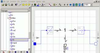
4 The Junctions II The Element Models Let us now look at the bond-graphic element models. dl The bond graph capacitor may serve as an example. The ThreePortZero partial model drags the three bond connectors into the diagram window, and packs the individual bond variables into two vectors. Add text C=%C to icon window. Model Wrapping Although it is possible to model physical systems s manually down to the bond graph level, this may not always be convenient. The bond graph interface is the lowermost graphical interface that is still fully object-oriented. The interface is important as it keeps the distance between the lowermost graphical layer and the equation layer as small as possible. Higher level graphical layers can be built easily on top of the bond graph layer for enhanced convenience. The Bond Graph Electrical Library It is possible to wrap any other object-oriented oriented graphical modeling paradigm around the bond graph methodology. This was done with the analog electrical library that forms part of the standard library of Modelica. A new analog electrical library was created as part of the bond graph library. In this new library, the bottom layer graphical models were wrapped around a yet lower level bond graph layer. 4


5 The Wrapped Resistor Model The Spice-style resistor model has a thermal port carrying the heat generated tdby the resistor. it The Wrapped Resistor Model II Icon window The wrapper models convert the connectors between the three domains: electrical, thermal, and bond graph. Diagram window Equation window The Wrapped Resistor Model III The Wrapped Resistor Model IV Parameter window Diagram window 5


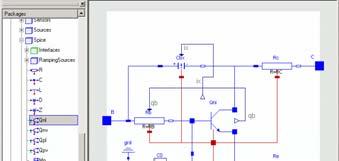


6 The Wrapped Resistor Model V The Bipolar Junction Transistor Icon window Diagram window The Bipolar Junction Transistor II The Bipolar Junction Transistor III 6


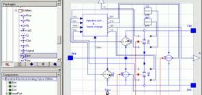
7 The Bipolar Junction Transistor IV The Bipolar Junction Transistor V The Bipolar Junction Transistor VI Inverter Circuit 7


, The Modelica Bond Graph Library, Proc. 4 th Intl.")
, Electronic Circuit Modeling and Simulation in Modelica, Proc.")
8 Inverter Circuit II Simulation Results Initial number of equations Simulation Time Final number of equations References Cellier, F.E. and R.T. McBride (2003), Object-oriented modeling of complex physical systems using the Dymola bond-graph library, Proc. ICBGM 03, Itl Intl. Conf. Bond Graph Modeling and Simulation, Orlando, FL, pp Cellier, F.E. and A. Nebot (2005), The Modelica Bond Graph Library, Proc. 4 th Intl. Modelica Conference, Hamburg, Germany, Vol.1, pp Clli Cellier, F.E., C. Clauß, and A. Urquía (2007), Electronic Circuit Modeling and Simulation in Modelica, Proc. 6 th Eurosim Congress, Ljubljana, Slovenia, Vol.2, pp Cellier, F.E. (2007), The Dymola Bond-Graph Library, Version
Improvements in BondLib, the Modelica Bond Graph Library
 Improvements in BondLib, the Modelica Bond Graph Library Alberto de la Calle, François E. Cellier, Luis J. Yebra, Sebastián Dormido Automatic Control Group, CIEMAT-Plataforma Solar de Almería, Tabernas,
Multi-bond Graphs. Table of Contents. A Planar Pendulum
 Multi-bond Graphs We shall today look at vectors of bonds, called multi-bonds. Especially when dealing with 2D and 3D mechanics, the d Alembert principle must be applied to each degree of freedom separately.
ELECTRONIC CIRCUIT MODELING AND SIMULATION IN MODELICA
 ELECTRONIC CIRCUIT MODELING AND SIMULATION IN MODELICA François E. Cellier 1, Christoph Clauß 2, Alfonso Urquía 3 1 ETH Zurich, Department of Computer Science, ETH-Zentrum, CH-8029 Zurich, Switzerland
1 Although other ways of exporting like using the 2 s 1
 A Novel Proposal on how to Parameterize Models in Dymola Utilizing External Files under Consideration of a Subsequent Model Export using the Functional Mock-Up Interface Thomas Schmitt 1 Markus Andres
Variable Structure Modeling for Vehicle Refrigeration Applications
 Variable Structure Modeling for Vehicle Refrigeration Applications Imke Krüger Alexandra Mehlhase Gerhard Schmitz Hamburg University of Technology, Department of Technical Thermodynamics Denickestr. 17,
Numerical Simulation of Dynamic Systems XXIV
 Numerical Simulation of Dynamic Systems XXIV Prof. Dr. François E. Cellier Department of Computer Science ETH Zurich May 14, 2013 Introduction Introduction A number of important simulation applications
Object-oriented Modelling of Physical Systems with Modelica using Design Patterns
 Workshop on System Design Automation SDA2000, Rathen, March 13-14, 209-216 Object-oriented Modelling of Physical Systems with Modelica using Design Patterns Christoph Clauß, Thomas Leitner, André Schneider,
Department of Electrical and Electronics Engineering SSN College of Engineering
 1 Department of Electrical and Electronics Engineering SSN College of Engineering 2 TABLE OF CONTENTS EAGLE CADSOFT Professional 2 Getting Started 3 Toolbar quick reference 5 Creating the Schematic 6 Creating
INTRODUCTION. Mechanical Considerations APPLICATION NOTE Z86E21 THERMAL PRINTER CONTROLLER ZILOG
 ZILOG DESIGNING A LOW-COST THERMAL PRINTER USING THE Z86E21 TO CONTROL THE OPERATING CURRENT ON LOW-COST THERMAL PRINTERS PROVIDES DESIGN FLEXIBILITY AND HELPS SAFEGUARD PERFORMANCE. INTRODUCTION Compact
Manual for Wavenology EM Graphic Circuit Editor. Wave Computation Technologies, Inc. Jan., 2013
 Manual for Wavenology EM Graphic Circuit Editor Wave Computation Technologies, Inc. Jan., 2013 1 Introduction WCT Graphic Circuit Editor is used to build a Spice circuit model in WCT EM full wave simulator.
SPICE Models: ROHM Voltage Detector ICs
 SPICE Models: ROHM Voltage Detector ICs BD48 G/FVE,BD49 G/FVE,BD52 G/FVE,BD53 G/FVE, No.10006EAY01 1. INTRODUCTION 1.1 SPICE SPICE is a general-purpose circuit-simulation program for nonlinear DC, nonlinear
PSpice Tutorial. Physics 160 Spring 2006
 PSpice Tutorial This is a tutorial designed to guide you through the simulation assignment included in the first homework set. You may either use the program as installed in the lab, or you may install
QUICK START GUIDE FOR DEMONSTRATION CIRCUIT 995A ADJUSTABLE LDO LINEAR REGULATOR LT3080EDD DESCRIPTION
 LT3080EDD DESCRIPTION Demonstration circuit 995A is an adjustable 1.1A linear regulator featuring LT 3080. Architected as a precision current source and voltage follower, it allows this new regulator to
ModelicaML: Getting Started Issue April 2012
 ModelicaML: Getting Started Issue 1.6.5 13. April 2012 Wladimir Schamai EADS Innovation Works (Hamburg, Germany) Linkoping University (Linkoping, Sweden) Abstract: This document provides a short introduction
Method of analysis. Bởi: Sy Hien Dinh
 Method of analysis Bởi: Sy Hien Dinh INTRODUCTION Having understood the fundamental laws of circuit theory (Ohm s law and Kirchhhoff s laws), we are now prepared to apply to develop two powerful techniques
Hybrid dynamics in Modelica: should all events be considered synchronous. Ramine Nikoukhah INRIA. Modelica/Scicos
 Hybrid dynamics in Modelica: should all events be considered synchronous Ramine Nikoukhah INRIA EOOLT 2007 Modelica/Scicos Modelica: language for modeling physical systems. Originally continuous-time modeling
SIMULATOR TO FMU: A PYTHON UTILITY TO SUPPORT BUILDING SIMULATION TOOL INTEROPERABILITY
 2018 Building Performance Analysis Conference and SimBuild co-organized by ASHRAE and IBPSA-USA Chicago, IL September 26-28, 2018 SIMULATOR TO FMU: A PYTHON UTILITY TO SUPPORT BUILDING SIMULATION TOOL
Discharge by touching: BNC coax shield, outlet metal cover plate, wire connected to GND
 Step-down transformer Very High Voltage Very Low Current Lower Voltage, 110V Power Station Grounding contact (3rd wire) Faulty wiring makes box hot!! Current path splits: 1) to ground (mostly) 2) through
POWER CONTROL BOARD. removed if a sampling of the +5V digital is not. desired. If any one of them is out of range all +5V
 POWER CONTROL BOARD The power control board conditions the DC power to protect the CCD from overvoltage transients. The board passes three analog voltages (high voltage, nominally +36V, and low voltages,
Audio Specialties Group Products Division MODEL AOB-2 INTERCOM-AUDIO INTERFACE ADAPTOR
 Audio Specialties Group Products Division MODEL AOB-2 INTERCOM-AUDIO INTERFACE ADAPTOR 11/18/2011 1 Section 1 Introduction/Capabilities 1.1 Introduction The AOB-2 Audio Interface Adapter provides a convenient
Audio Specialties Group Products Division MODEL AOB-2 INTERCOM-AUDIO INTERFACE ADAPTOR
 Audio Specialties Group Products Division MODEL AOB-2 INTERCOM-AUDIO INTERFACE ADAPTOR 1 Section 1 Introduction/Capabilities 1.1 Introduction The AOB-2 Audio Interface Adapter provides a convenient and
HARDWARE MANUAL TMCM-6110 V TRINAMIC Motion Control GmbH & Co. KG Hamburg, Germany. MODULES FOR STEPPER MOTORS
 MODULES FOR STEPPER MOTORS MODULES V.0 HARDWARE MANUAL + + TMCM-60 6-axes stepper controller / driver up to.a RMS / 24V DC USB, CAN, RS48 + + TRINAMIC Motion Control GmbH & Co. KG Hamburg, Germany www.trinamic.com
Activation Inheritance in Modelica
 Activation Inheritance in Modelica Ramine Nikoukhah INRIA, BP 05, 7853 Le Chesnay, France ramine.nikoukhah@inria.fr Abstract Modelica specifies two types of s: the s defined directly in the "" section,
ARENALib: A Modelica Library for Discrete-Event System Simulation
 ARENALib: A Modelica Library for Discrete-Event System Simulation ARENALib: A Modelica Library for Discrete-Event System Simulation Victorino S. Prat Alfonso Urquia Sebastian Dormido Departamento de Informática
FPGA Power Management and Modeling Techniques
 FPGA Power Management and Modeling Techniques WP-01044-2.0 White Paper This white paper discusses the major challenges associated with accurately predicting power consumption in FPGAs, namely, obtaining
CHAPTER 5. Voltage Regulator
 CHAPTER 5 Voltage Regulator In your robot, the energy is derived from batteries. Specifically, there are two sets of batteries wired up to act as voltage sources; a 9V battery, and two 1.5V batteries in
A Systematic Design Approach to Thermal-Electrical Power Electronics Integration
 A Systematic Design Approach to Thermal-Electrical Power Electronics Integration Didier Cottet 1), Uwe Drofenik 2), Jean-Marc Meyer 3) 1) ABB Switzerland Ltd., Corporate Research, CH-5405 Baden-Dättwil
RAJIV GANDHI COLLEGE OF ENGINEERING AND TECHNOLOGY DEPARTMENT OF ECE QUESTION BANK- EDC SEMESTER - III UNIT I : SEMICONDUCTOR DIODS PART A
 RAJIV GANDHI COLLEGE OF ENGINEERING AND TECHNOLOGY DEPARTMENT OF ECE QUESTION BANK- EDC SEMESTER - III UNIT I : SEMICONDUCTOR DIODS 1. Define Electronics. 2. What is meant by forbidden energy gap. 3. Classify
Pololu 12V Step-Up/Step-Down Voltage Regulator S10V2F12
 Pololu 12V Step-Up/Step-Down Voltage Regulator S10V2F12 Overview The Pololu step-up/step-down voltage regulator S10V2F12 is a switching regulator (also called a switched-mode power supply (SMPS) or DC-to-DC
Cadence Tutorial A: Schematic Entry and Functional Simulation Created for the MSU VLSI program by Andrew Mason and the AMSaC lab group.
 Cadence Tutorial A: Schematic Entry and Functional Simulation Created for the MSU VLSI program by Andrew Mason and the AMSaC lab group. Revision Notes: Aug. 2003 update and edit A. Mason add intro/revision/contents
Modelica3D. Platform Independent Simulation Visualization. Christoph Höger. Technische Universität Berlin Fraunhofer FIRST
 Modelica3D Platform Independent Simulation Visualization Christoph Höger Technische Universität Berlin Fraunhofer FIRST c Fraunhofer FIRST/TU Berlin 6. Februar 2012 Motivation - Goal Dymola MultiBody Visualization
Towards Unified System Modeling with the ModelicaML UML Profile
 Towards Unified System Modeling with the ModelicaML UML Profile Adrian Pop, David Akhvlediani, Peter Fritzson Programming Environments Lab, Department of Computer and Information Science Linköping University,
Digital Fundamentals. Integrated Circuit Technologies
 Digital Fundamentals Integrated Circuit Technologies 1 Objectives Determine the noise margin of a device from data sheet parameters Calculate the power dissipation of a device Explain how propagation delay
VP603. CRT Display Video Output Amplifier: High-Voltage, Wideband Amplification
 Ordering number : EN5542A Wideband Output Module (Video Pack) VP603 CRT Display Video Output Amplifier: High-Voltage, Wideband Amplification Function Three-channel video output circuit for CRT displays
OrCad & Spice Tutorial By, Ronak Gandhi Syracuse University
 OrCad & Spice Tutorial By, Ronak Gandhi Syracuse University Brief overview: OrCad is a suite of tools from Cadence for the design and layout of circuit design and PCB design. We are currently using version
Generic FMI-compliant Simulation Tool Coupling
 Edmund Widl 1 Wolfgang Müller 2 1 Center for Energy, AIT Austrian Institute of Technology, Austria, edmund.widl@ait.ac.at 2 Institute of Analysis and Scientific Computing, TU Wien, Austria, wolfgang.mueller@student.tuwien.ac.at
Architecture-Centric Evolution in Software Product Lines:
 Architecture-Centric Evolution in Software Product Lines: Position Paper Hassan Gomaa Department of Information and Software Engineering George Mason University Fairfax, Virginia 22030, USA hgomaa@gmu.edu
ELECTRONIC INSTRUMENTATION AND SYSTEMS LABORATORY
 ELECTRONIC INSTRUMENTATION AND SYSTEMS LABORATORY DEPARTMENT OF ELECTRICAL AND COMPUTER ENGINEERING MICHIGAN STATE UNIVERSITY I. TITLE: Lab IX - Light Activated Exhaust Fan II. PURPOSE: One use of bipolar
EAGLE Schematic Software Cornerstone Electronics Technology and Robotics II
 EAGLE Schematic Software Cornerstone Electronics Technology and Robotics II Administration: o Prayer EAGLE Light Edition: o The name EAGLE is an acronym which stands for Easily Applicable Graphical Layout
Module 2, Add on lesson Introduction to the NXT and Mindstorms software. Student. 45 minutes
 Module 2, Add on lesson Introduction to the NXT and Mindstorms software Student 45 minutes Purpose of this lesson Write a basic program using LEGO Mindstorms Download and run programs on the NXT Materials
Powering Up and Programming the ProcessorPM isppac-powr605
 the ProcessorPM isppac-powr605 April 2011 Application Note AN6082 Introduction This application note discusses the states of the ProcessorPM isppac -POWR605 device s open drain logic outputs (IN_OUT1 to
SAMPLE HEAT PUMP WIRING DIAGRAMS
 When multiple switches are connected in series with each other, they all must be in the closed position for current to travel through the circuit, thereby energizing the load. Safety switches, for example,
Introduction to Labview and Temperature Measurement
 Introduction to Labview and Temperature Measurement Objective This lab is intended to familiarize you with the LABVIEW software and the data acquisition board used in this class and with temperature measurements
EE261 Computer Project 1: Using Mentor Graphics for Digital Simulation
 EE261 Computer Project 1: Using Mentor Graphics for Digital Simulation Introduction In this project, you will begin to explore the digital simulation tools of the Mentor Graphics package available on the
GETTING STARTED WITH ADS
 ADS Startup Tutorial v2 Page 1 of 17 GETTING STARTED WITH ADS Advanced Design System (ADS) from Agilent Technologies is an extremely powerful design tool for many aspects of electrical and computer engineering
TECH 3821 Lab #2 Relay Driver with Computer Control
 TECH 3821 Lab #2 Relay Driver with Computer Control Name: Background: One of the most basic controls in industry is the ability to turn things on and off. As we saw in Lab #1, a relay is often used to
Introduction to PSpice
 Introduction to PSpice Simulation Software 1 The Origins of SPICE In the 1960 s, simulation software begins CANCER Computer Analysis of Nonlinear Circuits, Excluding Radiation Developed at the University
Modelica Change Proposal MCP-0021 Component Iterators Status: Under Evaluation , version v2, #1848
 Modelica Change Proposal MCP-0021 Component Iterators Status: Under Evaluation 2015-12-08, version v2, #1848 Summary It is proposed to generalize iterator expressions so that a class name can be used as
Table of Contents. 1 Introduction. 2 Reliability Predictions for Electronic Equipment. 3 Steady State Failure Rate Prediction for Devices
 Reliability Prediction Procedure for Electronic Equipment SR-332 Table of Contents Table of Contents 1 Introduction 1.1 Purpose and Scope.................................. 1 1 1.2 Changes........................................
- create new schematic to the new project, PCB design begins with a schematic diagram, which present how components are connected
 Eagle 8.x tutorial - create a new project, Eagle designs are organized as projects - create new schematic to the new project, PCB design begins with a schematic diagram, which present how components are
MAX6692 Evaluation System/Evaluation Kit
 19-2707; Rev 0; 10/02 MAX6692 Evaluation System/Evaluation Kit General Description The MAX6692 evaluation system (EV system) consists of a MAX6692 evaluation kit (EV kit) and a companion Maxim SMBus interface
Application Note AN V1.3 August Module with adapted driver electronics
 MIPAQ serve Edition 2013-08-16 Published by Infineon Technologies AG 59568 Warstein, Germany Infineon Technologies AG 2013. All Rights Reserved. Attention please! THE INFORMATION GIVEN IN THIS APPLICATION
PSpice with Orcad 10
 PSpice with Orcad 10 1. Creating Circuits Using PSpice Tutorial 2. AC Analysis 3. Step Response 4. Dependent Sources 5. Variable Phase VSin Source Page 1 of 29 Creating Circuits using PSpice Start Orcad
PHY Microprocessor Interfacing Techniques LabVIEW Tutorial - Part I Beginning at the Beginning
 PHY 406 - Microprocessor Interfacing Techniques LabVIEW Tutorial - Part I Beginning at the Beginning Introduction One of the main objectives of this course is to teach you how to gather data using computers
DESIGN AND PERFORMANCE ANALYSIS OF CARRY SELECT ADDER
 DESIGN AND PERFORMANCE ANALYSIS OF CARRY SELECT ADDER Bhuvaneswaran.M 1, Elamathi.K 2 Assistant Professor, Muthayammal Engineering college, Rasipuram, Tamil Nadu, India 1 Assistant Professor, Muthayammal
Lesson 2: DC Bias Point Analysis
 2 Lesson 2: DC Bias Point Analysis Lesson Objectives After you complete this lesson you will be able to: Create a simulation profile for DC Bias analysis Netlist the design for simulation Run a DC Bias
ME 3210: Mechatronics Signal Conditioning Circuit for IR Sensors March 27, 2003
 ME 3210: Mechatronics Signal Conditioning Circuit for IR Sensors March 27, 2003 This manual and the circuit described have been brought to you by Adam Blankespoor, Roy Merril, and the number 47. The Problem:
RCTI, SOLA, AHMEDABAD INFORMATION TECHNOLOGY DEPARTMENT. SUBJECT :- Advanced Computer Programming ( )
") RCTI, SOLA, AHMEDABAD INFORMATION TECHNOLOGY DEPARTMENT SUBJECT :- Advanced Computer Programming (3320702) Assignment 1 (Unit I - Array) Define an array. Explain types of array. Give advantage and disadvantage
RCTI, SOLA, AHMEDABAD INFORMATION TECHNOLOGY DEPARTMENT SUBJECT :- Advanced Computer Programming (3320702) Assignment 1 (Unit I - Array) Define an array. Explain types of array. Give advantage and disadvantage
DSP Research Project
 DSP Research Project The digital signal processing (DSP) research project is a core component of the Physics 351 digital electronics course. The research project component is structured as design, construction,
TD62M8600FG TD62M8600FG 8CH LOW SATURATION VOLTAGE SOURCE DRIVER FEATURES SCHEMATICS PIN CONNECTION (TOP VIEW)
") TOSHIBA BIPOLAR DIGITAL INTEGRATED CIRCUIT MULTI CHIP TD62M8600FG TD62M8600FG 8CH LOW SATURATION VOLTAGE SOURCE DRIVER TD62M8600FG is Multi Chip IC incorporates 8 low saturation discrete transistors equipped
TOSHIBA BIPOLAR DIGITAL INTEGRATED CIRCUIT MULTI CHIP TD62M8600FG TD62M8600FG 8CH LOW SATURATION VOLTAGE SOURCE DRIVER TD62M8600FG is Multi Chip IC incorporates 8 low saturation discrete transistors equipped
Experiment 1 Electrical Circuits Simulation using Multisim Electronics Workbench: An Introduction
 Experiment 1 Electrical Circuits Simulation using Multisim Electronics Workbench: An Introduction Simulation is a mathematical way of emulating the behavior of a circuit. With simulation, you can determine
Applying the IRStream Retrieval Engine to INEX 2003
 Applying the IRStream Retrieval Engine to INEX 2003 Andreas Henrich, Volker Lüdecke University of Bamberg D-96045 Bamberg, Germany {andreas.henrich volker.luedecke}@wiai.unibamberg.de Günter Robbert University
IOA and IOB Inputs and Outputs Expansion Module
 Installation, Configuration and Operation Guide IOA and IOB Inputs and Outputs Expansion Module l. SAFETY INFORMATION All safety procedures described in the manual must be followed. ll. GENERAL INFORMATION
Wiring guide for dual-output vibration and temperature sensors
 Wiring guide for dual-output vibration and temperature sensors Wilcoxon manufactures three types of sensors that output a vibration signal and a DC voltage proportional to the temperature. The temperature
unit : mm Parameter Symbol Conditions Ratings Unit
 Ordering number: EN3947B Monolithic Digital IC LB1836M Low-saturation, Bidirectional Motor Driver for Low-voltage Applications Overview The LB1836M is a low-saturation two-channel bidirectional motor driver
Module 2, Add on lesson Introduction to the NXT and Mindstorms software. Teacher. 45 minutes
 Module 2, Add on lesson Introduction to the NXT and Mindstorms software Teacher 45 minutes Purpose of this lesson Write a basic program using LEGO Mindstorms Download and run programs on the NXT Materials
Important Characteristics of VHDL-AMS and Modelica with Respect to Model Exchange
 Important Characteristics of VHDL-AMS and Modelica with espect to Model Exchange Olaf Enge-osenblatt, Joachim Haase, Christoph Clauß Fraunhofer Institute for Integrated Circuits, Design Automation Division,
COMPUTER-AIDED DESIGN OF MECHATRONIC SYSTEMS USING 20-SIM 3.0
 Jan F. Broenink 1, Christian Kleijn 2 1 Control Laboratory (Faculty EE) and C. J. Drebbel Institute on Systems Engineering, University of Twente, Enschede Netherlands. E-mail: J.F.Broenink@el.utwente.nl
Integrated Graphical Program in Lumousoft Visual Programming Language
 142 Int'l Conf. Embedded Systems, Cyber-physical Systems, & Applications ESCS'16 Integrated Graphical Program in Lumousoft Visual Programming Language Xianliang Lu Lumousoft Inc. Waterloo Ontario Canada
Modelica Change Proposal MCP-0019 Flattening (In Development) Proposed Changes to the Modelica Language Specification Version 3.
 Proposed Changes to the Modelica Language Specification Version 3.") Modelica Change Proposal MCP-0019 Flattening (In Development) Proposed Changes to the Modelica Language Specification Version 3.3 Revision 1 Table of Contents Preface 3 Chapter 1 Introduction 3 Chapter
Modelica Change Proposal MCP-0019 Flattening (In Development) Proposed Changes to the Modelica Language Specification Version 3.3 Revision 1 Table of Contents Preface 3 Chapter 1 Introduction 3 Chapter
EE 330 Spring Laboratory 2: Basic Boolean Circuits
 EE 330 Spring 2013 Laboratory 2: Basic Boolean Circuits Objective: The objective of this experiment is to investigate methods for evaluating the performance of Boolean circuits. Emphasis will be placed
Orcad Tutorial: Oscillator design and Simulation Schematic Design and Simulation in Orcad Capture CIS Full Version
 Orcad Tutorial: Oscillator design and Simulation Prof. Law Schematic Design and Simulation in Orcad Capture CIS Full Version Notation: To simplify what one should click to perform a task, the following
Electronic Design Automation Using Object Oriented Electronics
 American J. of Engineering and Applied Sciences 3 (1): 121-127, 2010 ISSN 1941-7020 2010 Science Publications Electronic Design Automation Using Object Oriented Electronics 1 Walid M. Aly and 2 Mohamed
PinPoint II. Circuit board test & diagnostic system. diagnosys.com
 PinPoint II Circuit board test & diagnostic system diagnosys.com Multi-strategy testing for confidence... Test of Individual Components and Edge connectors testing [1] The PinPoint system performs tests
TRANSISTORIZED INVERTER -INSTRUCTION MANUAL- RELAY OUTPUT FR-A5AR
 TRANSISTORIZED INVERTER -INSTRUCTION MANUAL- RELAY OUTPUT FR-A5AR Thank you for choosing the Mitsubishi transistorized inverter option unit. This instruction manual gives handling information and precautions
HARDWARE MANUAL TMCM Hardware Version V1.2 UNIQUE FEATURES: TRINAMIC Motion Control GmbH & Co. KG Hamburg, Germany.
 MODULE FOR STEPPER MOTORS MODULE Hardware Version V1.2 HARDWARE MANUAL + + TMCM-1021 Stepper Motor with Controller / Driver 0.7A RMS / 24V DC RS485 Interface + + UNIQUE FEATURES: TRINAMIC Motion Control
NEW Series SSH Output to 75A, 510 Vac with Diagnostics High Industrial Performance (HIPpak) Solid-State Relays
 Solid-State Relays") FEATURES/BENEFITS Zero-cross models with system diagnostics Very low zero-cross turn-on voltage Input and output protection and control LED standard IP20 protection by flaps on terminals With double removable
FEATURES/BENEFITS Zero-cross models with system diagnostics Very low zero-cross turn-on voltage Input and output protection and control LED standard IP20 protection by flaps on terminals With double removable
MAX6642 Evaluation System/Evaluation Kit
 19-3417; Rev 0; 9/04 MAX6642 Evaluation System/Evaluation Kit General Description The MAX6642 evaluation kit (EV kit) is an assembled and tested PC board with a mounted MAX6642. The EV kit allows full
Once you have the latest version of the EAGLE software downloaded & installed, launch the program to create your new project:
 This tutorial will introduce the basic operations available with the EAGLE (Easily Applicable Graphical Layout Editor) PCB software. This tutorial is based on EAGLE Lite version 5.10.0 for Windows. The
Modeling physical properties. Controller, plant and environment model
 Modeling physical properties Controller, plant and environment model 1 Traceability Platform-based systems design Verification and Validation Requirements HW library Functional model HW/SW allocation Platform
How TMG Uses Elements and Nodes
 Simulation: TMG Thermal Analysis User's Guide How TMG Uses Elements and Nodes Defining Boundary Conditions on Elements You create a TMG thermal model in exactly the same way that you create any finite
Laboratory Exercise 1
 Laboratory Exercise 1 Switches, Lights, and Multiplexers The purpose of this exercise is to learn how to connect simple input and output devices to an FPGA chip and implement a circuit that uses these
THE DESIGNER'S GUIDE TO VERILOG-AMS First Edition June 2004
 THE DESIGNER'S GUIDE TO VERILOG-AMS First Edition June 2004 KENNETH S. KUNDERT Cadence Design Systems OLAF ZINKE Cadence Design Systems k4 Kluwer Academic Publishers Boston/Dordrecht/London Chapter 1 Introduction
PI5USB66. USB Charge Controller IC for Single USB Port. Features. Description. Pin Configuration. Applications
 Features ÎÎManages communication to allow charging to occur ÎÎProvides multiple modes of charging to ensure all of the following specs can be met: DCP mode per USB BC.0,., &. spec YD/T - 59 charger spec
Modeling Technical Systems [ ] Mag MA MA Schweiger Gerald TU Graz Spring 2017
![Modeling Technical Systems [ ] Mag MA MA Schweiger Gerald TU Graz Spring 2017](/thumbs/93/112845817.jpg "Modeling Technical Systems [ ] Mag MA MA Schweiger Gerald TU Graz Spring 2017") 1 Modeling Technical Systems [716.055] Mag MA MA Schweiger Gerald TU Graz Spring 2017 Outline Scope of the course Introduction Modelica Basics Introduction to Dymola Scope of the course Introduction to
1 Modeling Technical Systems [716.055] Mag MA MA Schweiger Gerald TU Graz Spring 2017 Outline Scope of the course Introduction Modelica Basics Introduction to Dymola Scope of the course Introduction to
Feedback Techniques for Dual-rail Self-timed Circuits
 This document is an author-formatted work. The definitive version for citation appears as: R. F. DeMara, A. Kejriwal, and J. R. Seeber, Feedback Techniques for Dual-Rail Self-Timed Circuits, in Proceedings
Engineering 1000 Chapter 6: Abstraction and Modeling
 Engineering 1000 Chapter 6: Abstraction and Modeling Outline Why is abstraction useful? What are models? how are models different from theory and simulation? Examples from microelectronics Types of model
Chapter 5 Making Life Easier with Templates and Styles
 Chapter 5: Making Life Easier with Templates and Styles 53 Chapter 5 Making Life Easier with Templates and Styles For most users, uniformity within and across documents is important. OpenOffice.org supports
PSI-MODEM-SHDSL/PB. Broadband PROFIBUS extender, SHDSL PROFIBUS leased line modem. Data sheet _en_03. 1 Description. 1.
 PSI-MODEM-/PB Broadband PROFIBUS extender, PROFIBUS leased line modem Data sheet 104396_en_03 1 Description PHOENIX CONTACT 2013-08-21 1.1 Features The PROFIBUS extender can be used to easily network PROFIBUS
Tutorial 3: Using the Waveform Viewer Introduces the basics of using the waveform viewer. Read Tutorial SIMPLIS Tutorials SIMPLIS provide a range of t
 Tutorials Introductory Tutorials These tutorials are designed to give new users a basic understanding of how to use SIMetrix and SIMetrix/SIMPLIS. Tutorial 1: Getting Started Guides you through getting
ELEC 2200 Digital Logic Circuits
 ELEC 22 Digital Logic Circuits Charles E. Stroud, Professor Dept. of Electrical & Computer Engineering Office: 325 Broun Hall Email: cestroud@eng.auburn.edu Text: Digital Logic Circuit Analysis & Design
Analog Simulation and Testing via FPAA Jeffrey Teng, Fall 2016
 Analog Simulation and Testing via FPAA Jeffrey Teng, Fall 2016 Introduction This document discusses the process of performing real measurements on analog circuits using an FPAA remote system. The software
Proceedings of the 4th International Modelica Conference, Hamburg, March 7-8, 2005, Gerhard Schmitz (editor)
") Proceedings of the 4th International Modelica Conference, Hamburg, March 7-8, 2005, Gerhard Schmitz (editor) A Siemers, I Nakhimovski, D Fritzson Linköping University, Sweden Meta-modelling of Mechanical
Proceedings of the 4th International Modelica Conference, Hamburg, March 7-8, 2005, Gerhard Schmitz (editor) A Siemers, I Nakhimovski, D Fritzson Linköping University, Sweden Meta-modelling of Mechanical
A Novel Implementation of Reversible Multiplexer Design Using MZI
 A Novel Implementation of Reversible Multiplexer Design Using MZI Abstract: Atluri Sarath Raja M.Tech, Usha Rama Engineering College, Telaprolu, Vijayawada, Andhra Pradesh. Reversible logic; transforms
Hobbes LANtest Pro Remote Network Cable Tester
 1 (This manual covers the following models) User Manual 256652A 256652AT 256652A/IDT 256652A/TK 256652A/TFK LANtest Pro (previous 256652LB) LANtest Pro with tone generator LANtest Pro and 4 remote IDs
Chapter 5: The beast of bias
 Chapter 5: The beast of bias Self-test answers SELF-TEST Compute the mean and sum of squared error for the new data set. First we need to compute the mean: + 3 + + 3 + 2 5 9 5 3. Then the sum of squared
Setting up an initial ".tcshrc" file
 ECE445 Fall 2005 Introduction to SaberSketch The SABER simulator is a tool for computer simulation of analog systems, digital systems and mixed signal systems. SaberDesigner consists of the three tools,
For Powerstax D2000 DC-DC Power Cartridges Used in Powerstax S6000 Power Shelves
 POWERSTAX PLC APPLICATION NOTES For Powerstax D2000 DC-DC Power Cartridges Used in Powerstax S6000 Power Shelves Powerstax D2000 DC-DC Power Cartridge REMOTE SENSE The remote sense signals SENSE+ and SENSE-
icex-cmtm General specs and Installation guide
 icex-cmtm General specs and Installation guide 1. General view 2. Specifications 2.1. Common specs: Ethernet 1 x 10/100Base/T, RJ45 connector with traffic and link LED Serial Interface 1 x RS232/485 USB
An Easy-to-use Generic Model Configurator for Models in Multiple Tool Formats
 An Easy-to-use Generic Model Configurator for Models in Multiple Tool Formats Vadim Engelson 1, Peter Fritzson 1, Ulf Sellgren 2 1 Department of Computer and Information Science Linköping University SE-58183