Attach to this tutorial, there are some drawings to create the CAD models with Solid Works.
|
|
|
- Donna Black
- 5 years ago
- Views:
Transcription
1 Modeling and Simulation Tutorial 1. (Slider Mechanism) Objective: To Create Slider Mechanism Elements to Use: SolidWorks Cosmos Motion Dynamics Books Description: This tutorial explains how to set up different kinds of Joints in a Cosmos Motion Mechanism, besides introduces students how to set up concentric and revolute joints in a simple mechanism. This exercise is taken from a Dynamic Books (Meriam) 1
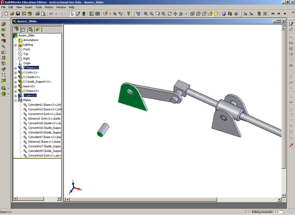
2 Creation of the mechanism Elements. Attach to this tutorial, there are some drawings to create the CAD models with Solid Works. Creation of SolidWorks Assembly Create a new assembly in SolidWorks, browse for the part called base Select base part, and click on the screen, now browse for the file called link, and do the same procedure 2
3 Select the front face of the link and the back face of the support, select No in the dialog box that appears, and select coincident in the mate dialog box. 3

4 Back face of the support Front face of the link 4
5 Now, select the internal faces of the holes and click concentric. Open the file (part) Called Guide 5

6 Select the internal face of the hole and the outer surface of the guide pin, and click concentric Click on the back face of the link and the front face of the guide hub, select a distance of 0.5 inches, move the mechanism to get the following graphic. 6
7 Assembly of the support, link and guide 7

8 Open the file (part) called guide support, move or rotate it to make the hole concentric with the guide Select the internal face of the hole in the guide support, and the external face of the guide and click concentric 8

9 Now, open the base part again, select the internal face of the hole in the new base part, and the external face of one of the pin in the hub of the guide support and click concentric, click on the front face of the new base part and the front face of the pin in the guide support part and click coincident. 9
10 Click on the base of the every support part and click coincident 10
11 Create a distance constraint between every support (8 inches, no 9) see the figure. 11
12 Insert the base part, and click on the internal face of the hole and the external one of the pin, click concentric, if it is necessary select the bottom face of the bases part and click coincident. Select the front face of the new base part, the front face of the pin in the guide support part and select coincident 12
13 Now, insert the pin part and click the internal face of the hole in the link and the external face of the pin and select concentric Select the front face of the pin and front face of the first base and click distance (0.35 inches) 13
14 14
15 The final assembly has to look like this graphic. Now click on the motion button in the manager window, and the motion manager tree appears. 15
16 Now, the following parts have to be dragged to the moving parts branch: -Guide_Support -Guide -Link -Pin The following parts have to be dragged to the ground parts: -Base_1 -Base_2 -Base_3 16
17 The constraints have to look like this graphic. Click on the (+) sign of constraints in the motion manager tree, and click on the (+) of Joints and select the revolute that is on the base_1, right click on it and select properties and select the following parameters. 17


18 Click apply, Click, motion >options>simulation and select the following parameters Click the simulation button 18
19 Now, we are going to plot the velocity of the link Right click on velocity and create one 19


20 Select the link part, automatically the software assume that the point to calculate the velocity is the center of gravity of the link, it can be changed and another point can be selected Hide the velocity vector; velocity, and select velocity graphic, properties (Right click) Click on the simulation button twice, the simulation starts, when it has finished, click on velocity graphic again select plot, X component and Y component. 20
21 What is the max. X component of the Velocity in the link? What is the max. Y component of the Velocity in the link? Can you calculate the relative velocity between the guide and guide support?, if so what is the value. Note: the software automatically assume some materials properties for every element, it can be changed at any time. Go to materials properties and see what kind of materials are assumed for this mechanism 21
Analysis of a 4 Bar Crank-Rocker Mechanism Using COSMOSMotion
 Analysis of a 4 Bar Crank-Rocker Mechanism Using COSMOSMotion ME345: Modeling and Simulation Professor Frank Fisher Stevens Institute of Technology Last updated: June 29th, 2009 Table of Contents 1. Introduction
Introduction to Solid Modeling Using SolidWorks 2008 COSMOSMotion Tutorial Page 1
 Introduction to Solid Modeling Using SolidWorks 2008 COSMOSMotion Tutorial Page 1 In this tutorial, we will learn the basics of performing motion analysis using COSMOSMotion. Although the tutorial can
Step 1: Open the CAD model
 In this exercise you will learn how to: Ground a part Create rigid groups Add joints and an angle motor Add joints and an angle motor Run both transient and statics motion analyses Apply shape controls
Spring Assembly. in the Begin Assembly Property. on the Standard toolbar and click Add-Ins.
 Chapter 2 Spring Assembly A. Create New Assembly. Step 1. Click File Menu > New, click Assembly and OK. Step 2. Click Cancel Manager. in the Begin Assembly Property B. Enable Toolbox Browser. Step 1. If
Wheels and Axle. Chapter 7. Simples Machines. A. Save As. Step 1. If necessary, open your Track Assembly 15 file. B. Insert Truck Assembly.
 Chapter 7 Simples Machines Wheels and Axle A. Save As. Step 1. If necessary, open your Track Assembly 15 file. Step 2. Click File Menu > Save As. Step 3. Key-in WHEELS AND AXLE ASSEMBLY for the filename
Assembly Modeling Constraints
 Assembly Modeling Constraints College of Engineering Engineering Education Innovation Center Rev: 20130715 AJP Assembly Modeling Constraints 1 Assemblies Assemblies are collections of 3D parts that form
MSC.visualNastran Desktop FEA Exercise Workbook. Pin and Bracket Assembly: Vibration Simulation in 4D
 MSC.visualNastran Desktop FEA Exercise Workbook Pin and Bracket Assembly: Vibration Simulation in 4D WS24-2 Objectives This exercise is design to introduce vibration analysis in visualnastran Desktop.
SOLIDWORKS: Lesson 1 - Basics and Modeling. Introduction to Robotics
 SOLIDWORKS: Lesson 1 - Basics and Modeling Fundamentals Introduction to Robotics SolidWorks SolidWorks is a 3D solid modeling package which allows users to develop full solid models in a simulated environment
ME Week 11 Create Joints Project
 One of the most important elements of dynamic simulation is setting up and verifying that proper joints are created. Joints are links between two rigid components that applies force from the first component
SOLIDWORKS: Lesson 1 - Basics and Modeling. UCF Engineering
 SOLIDWORKS: Lesson 1 - Basics and Modeling Fundamentals UCF Engineering SolidWorks SolidWorks is a 3D solid modeling package which allows users to develop full solid models in a simulated environment for
Tutorial: Using SolidWorks to assemble an off-the-shelf lens system
 Tutorial: Using SolidWorks to assemble an off-the-shelf lens system Jennifer Harwell College of Optical Sciences, University of Arizona November 29, 2010 Introduction When designing an optical system,
Lesson 4: Assembly Basics
 4 Lesson 4: Assembly Basics Goals of This Lesson Understand how parts and assemblies are related. Create and modify the part Tutor2 and create the Tutor assembly. Tutor1 Tutor2 Tutor assembly Before Beginning
Airplane Assembly. SolidWorks 10 ASSEMBLY AIRPLANE Page 9-1
 Chapter 9 A. Insert Parts. Airplane Assembly Step 1. Click File Menu > New, click Assembly and OK. Step 2. Click Keep Visible in the Property Manager, Fig. 1. Step 3. Click Browse in the Property Manager,
Using Siemens NX 11 Software. Assembly example - Gears
 Using Siemens NX 11 Software Assembly example - Gears Based on a NX tutorial from the NX documentation 1. 1 Introduction. Start NX 11 and create a new assembly file called assembly_gear.prt. 2 Adding a
SOLIDWORKS Parametric Modeling with SDC. Covers material found on the CSWA exam. Randy H. Shih Paul J. Schilling
 Parametric Modeling with SOLIDWORKS 2015 Covers material found on the CSWA exam Randy H. Shih Paul J. Schilling SDC PUBLICATIONS Better Textbooks. Lower Prices. www.sdcpublications.com Powered by TCPDF
Appendix B: Certified SolidWorks Associate Sample Exam
 B Certified SolidWorks Associate (CSWA) The Certified SolidWorks Associate (CSWA) Certification Program provides the skills students need to work in the design and engineering fields. Successfully passing
Parametric Modeling with SolidWorks
 Parametric Modeling with SolidWorks 2012 LEGO MINDSTORMS NXT Assembly Project Included Randy H. Shih Paul J. Schilling SDC PUBLICATIONS Schroff Development Corporation Better Textbooks. Lower Prices. www.sdcpublications.com
Parametric Modeling with SOLIDWORKS 2017
 Parametric Modeling with SOLIDWORKS 2017 NEW Contains a new chapter on 3D printing Covers material found on the CSWA exam Randy H. Shih Paul J. Schilling SDC PUBLICATIONS Better Textbooks. Lower Prices.
SolidWorks Motion Study Tutorial
 SolidWorks Motion Study Tutorial By: Mohamed Hakeem Mohamed Nizar Mechanical Engineering Student- May 2015 South Dakota School of Mines & Technology August 2013 Getting Started This tutorial is for you
TUTORIAL 2. OBJECTIVE: Use SolidWorks/COSMOS to model and analyze a cattle gate bracket that is subjected to a force of 100,000 lbs.
 TUTORIAL 2 OBJECTIVE: Use SolidWorks/COSMOS to model and analyze a cattle gate bracket that is subjected to a force of 100,000 lbs. GETTING STARTED: 1. Open the SolidWorks program. 2. Open a new part file.
SolidWorks Assembly Files. Assemblies Mobility. The Mating Game Mating features. Mechanical Mates Relative rotation about axes
 Assemblies Mobility SolidWorks Assembly Files An assembly file is a collection of parts The first part brought into an assembly file is fixed Other parts are constrained relative to that part (or other
Lesson 12 Bottom-Up Assembly Modeling
 Lesson 12 Bottom-Up Assembly Modeling Upon successful completion of this lesson, you will be able to: Create a new assembly. Insert components into an assembly using all available techniques. Add mating
Speedway. Motion Study. Step 2. If necessary, turn on SolidWorks Motion. To turn on SolidWorks Motion, click Tools Menu > Add-Ins.
 Chapter 8 Speedway Motion Study A. Enable SolidWorks Motion. Step 1. If necessary, open your Speedway Assembly file. Step 2. If necessary, turn on SolidWorks Motion. To turn on SolidWorks Motion, click
Propeller. Chapter 13. Airplane. A. Base for Blade. Step 1. Click File Menu > New, click Part and OK.
 Chapter 13 Airplane Propeller A. Base for Blade. Step 1. Click File Menu > New, click Part and OK. Step 2. Click Top Plane in the Feature Manager and click Sketch toolbar, Fig. 1. from the Content Step
Learning. Modeling, Assembly and Analysis SOLIDWORKS Randy H. Shih SDC. Better Textbooks. Lower Prices.
 Learning SOLIDWORKS 2016 Modeling, Assembly and Analysis Randy H. Shih SDC PUBLICATIONS Better Textbooks. Lower Prices. www.sdcpublications.com Powered by TCPDF (www.tcpdf.org) Visit the following websites
Battery Holder 2 x AA
 Chapter 22 JSS Battery Holder 2 x AA A. Front Extrude. Step 1. Click File Menu > New, click Part Metric and OK. Step 2. Click Front Plane in the Feature Manager and click Sketch from the Context toolbar,
ME 3222 Design & Manufacturing II. Creating and Animating a Slider-Crank in Creo Elements (Version 2.0)
") ME 3222 Design & Manufacturing II Creating and Animating a Slider-Crank in Creo Elements (Version 2.0) Tom Chase February 18, 2016 Overview This document explains how to create a mechanism and animate
ME 3222 Design & Manufacturing II Creating and Animating a Slider-Crank in Creo Elements (Version 2.0) Tom Chase February 18, 2016 Overview This document explains how to create a mechanism and animate
ROSE-HULMAN INSTITUTE OF TECHNOLOGY
 More Working Model Today we are going to look at even more features of Working Model. Specifically, we are going to 1) Learn how to add ropes and rods. 2) Learn how to connect object using joints and slots.
Engineering. Statics Labs SDC. with SOLIDWORKS Motion Includes. Huei-Huang Lee. Better Textbooks. Lower Prices.
 Engineering Includes Video demonstrations of the exercises in the book Statics Labs with SOLIDWORKS Motion 2015 Huei-Huang Lee Multimedia Disc SDC PUBLICATIONS Better Textbooks. Lower Prices. www.sdcpublications.com
Introduction to SolidWorks Basics Materials Tech. Wood
 Introduction to SolidWorks Basics Materials Tech. Wood Table of Contents Table of Contents... 1 Book End... 2 Introduction... 2 Learning Intentions... 2 Modelling the Base... 3 Modelling the Front... 10
Assembly Modeling Constraints. ENGR 1182 SolidWorks 05
 Assembly Modeling Constraints ENGR 1182 SolidWorks 05 Today s Objectives Creating assemblies by constraining 3D parts together Movement and Location dictated by Constraints SW05 Activity SW05 Application
Assembly Motion Study
 Penny Hockey Chapter 10 Assembly Motion Study A. Rename Penny Mate. Step 1. Open your PENNY HOCKEY ASSEMBLY file. Step 2. Expand Mates in the Feature Manager and select the last Mate, Fig. 1. This should
SolidWorks 2015 User Interface
 SolidWorks 2015 User Interface SolidWorks a Dassault Systèmes Product Starting SolidWorks 1) On the desktop, double-click or from the start menu select: All Programs SOLIDWORKS 2015 SOLIDWORKS 2015. 2)
Flow Sim. Chapter 16. Airplane. A. Add-In. Step 1. If necessary, open your ASSEMBLY file.
 Chapter 16 A. Add-In. Step 1. If necessary, open your ASSEMBLY file. Airplane Flow Sim Step 2. Click Tools Menu > Add-Ins. Step 3. In the dialog box, scroll down to Flow Simulation and place a check in
SolidWorks. An Overview of SolidWorks and Its Associated Analysis Programs
 An Overview of SolidWorks and Its Associated Analysis Programs prepared by Prof. D. Xue University of Calgary SolidWorks - a solid modeling CAD tool. COSMOSWorks - a design analysis system fully integrated
Pro/Assembly. Figure Placing the first part: a) Create a new assembly called Tutorial2a. Accept the default template.
 Create a new assembly called Tutorial2a. Accept the default template.") Pro/Assembly An assembly is a collection of parts oriented and positioned together. Creating an assembly involves telling Pro/E how the various components fit together. To do this, we specify assembly
Pro/Assembly An assembly is a collection of parts oriented and positioned together. Creating an assembly involves telling Pro/E how the various components fit together. To do this, we specify assembly
Lab 6: Auxiliary Views, Cross-Sections, and Assemblies
 IAT106 IAT106 Spring 2017 IAT106: Spatial Thinking and Communicating Lab 6: Auxiliary Views, Cross-Sections, and Assemblies In this lab you will complete exercises on auxiliary views, cross-sections, and
ME Week 12 Piston Mechanical Event Simulation
 Introduction to Mechanical Event Simulation The purpose of this introduction to Mechanical Event Simulation (MES) project is to explorer the dynamic simulation environment of Autodesk Simulation. This
Tutorial: Package, analyze, and validate an OpticStudio sequential file in LensMechanix. By Esteban Carbajal, Senior Optomechanical Engineer
 Tutorial: Package, analyze, and validate an OpticStudio sequential file in LensMechanix By Esteban Carbajal, Senior Optomechanical Engineer November 2017 www.zemax.com/lmx/ LMxSales@zemaxZemax.com LMxSupport@zemaxZemax.com
Introduction to SolidWorks for Technology. No1: Childs Toy
 Introduction to SolidWorks for Technology No1: Childs Toy Table of Contents Table of Contents... 1 Introduction... 2 Part Modelling: Cab... 3 Part Modelling: Base... 6 Part Modelling: Wheel... 12 Assembly:
What Is SimMechanics?
 SimMechanics 1 simulink What Is Simulink? Simulink is a tool for simulating dynamic systems with a graphical interface specially developed for this purpose. Physical Modeling runs within the Simulink environment
Changes from SolidWorks 2003 to SolidWorks 2004
 Changes from SolidWorks 2003 to SolidWorks 2004 The changes from SolidWorks 2003 to SolidWorks 2004 are primarily cosmetic. Consequently, it is quite easy to use the current edition of Learning SolidWorks
Speedway. Motion Study. on the Standard toolbar and click Add-Ins. at the lower
 Chapter 8 Speedway Motion Study A. Enable SOLIDWORKS Motion. Step 1. If necessary, open your Speedway Assembly file. Step 2. If necessary, enable Motion, click the flyout of Options on the Standard toolbar
Fig. 1. Fig. 1. on the Standard Views toolbar. SolidWorks ASSEMBLY AIRPLANE Page 8-1
 Chapter 8 Airplane Assembly A. Insert Set of Parts. Step 1. Click File Menu > New, click Assembly and OK. Step 2. Click View Menu > Origins to display the origin. Step 3. Click Keep Visible in the Property
Engine with Propeller Tutorial (Professional)
") Engine with Propeller Tutorial (Professional) Copyright 2017 FunctionBay, Inc. All rights reserved. User and training documentation from FunctionBay, Inc. is subjected to the copyright laws of the Republic
Engine with Propeller Tutorial (Professional) Copyright 2017 FunctionBay, Inc. All rights reserved. User and training documentation from FunctionBay, Inc. is subjected to the copyright laws of the Republic
Introducing SolidWorks Assemblies
 Introducing SolidWorks Assemblies SAAST Robotics 2008 Assemblies Collection of related parts saved in one SW document file - *.sldasm Contains anywhere from 2 to over 1000 components or sub-assemblies
Flow Sim. Chapter 14 P-51. A. Set Up. B. Create Flow Simulation Project. Step 1. Click Flow Simulation. SolidWorks 10 Flow Sim P-51 Page 14-1
 Chapter 14 A. Set Up. P-51 Flow Sim Step 1. If necessary, open your ASSEMBLY file. Step 2. Click Tools Menu > Add-Ins. Step 3. In the dialog box, scroll down to Flow Simulation and place a check in the
Advanced Modelica Tutorial Exercises
 Advanced Modelica Tutorial Exercises Hilding Elmqvist, Dynasim Martin Otter, DLR Refine MultiBody/Engine Make Engine example model a reusable component 1. Manage parameters 2. Allow changing number of
Working Model Tutorial for Slider Crank
 Notes_02_01 1 of 15 1) Start Working Model 2D Working Model Tutorial for Slider Crank 2) Set display and units Select View then Workspace Check the X,Y Axes and Coordinates boxes and then select Close
CHAPTER 1: SOLIDWORKS 2008 USER INTERFACE
 CHAPTER 1: SOLIDWORKS 2008 USER INTERFACE Chapter Objective SolidWorks is a design software application used to model and create 2D and 3D sketches, 3D parts and assemblies, and 2D drawings. Chapter 1
Flow Sim. Chapter 12. F1 Car. A. Enable Flow Simulation. Step 1. If necessary, open your ASSEMBLY file.
 Chapter 12 F1 Car Flow Sim A. Enable Flow Simulation. Step 1. If necessary, open your ASSEMBLY file. Step 2. If necessary, turn on Flow Simulation, click the flyout of Options on the Standard toolbar and
#SEU Welcome! Solid Edge University 2016
 #SEU 2016 Welcome! Solid Edge University 2016 Realize innovation. Migrating SolidWorks Files to Solid Edge Steve Weatherwax Siemens PLM Realize innovation. SolidWorks Data Migration Tool Table of content
An Introduction to Motion Analysis Applications with SolidWorks Motion, Instructor Guide
 Engineering Design and Technology Series An Introduction to Motion Analysis Applications with SolidWorks Motion, Instructor Guide Dassault Systèmes SolidWorks Corporation 300 Baker Avenue Concord, Massachusetts
CO2 Car Assembly. in the Property Manager to place the part at the origin, Fig. 1. on the Assemblies toolbar. SolidWorks Assembly CO2 CAR Page 8-1
 Chapter 8 CO2 Car Assembly A. Insert Axles and Wheels. Step 1. Click File Menu > New, click Assembly Metric and OK. Step 2. Click Keep Visible in the Property Manager, Fig. 1. Step 3. Click Browse in the
Welcome to MSC.visualNastran 4D. 1.0 Installing MSC.visualNastran 4D
 Welcome to MSC.visualNastran 4D MSC.visualNastran 4D is the result of a twelve-year collaborative effort between professional engineers and software specialists. We are committed to providing you easy-to-use,
Questions? Page 1 of 22
 Learn the User Interface... 3 Start BluePrint-PCB... 4 Import CAD Design Data... 4 Create a Panel Drawing... 5 Add a Drill Panel... 5 Selecting Objects... 5 Format the Drill Panel... 5 Setting PCB Image
Solid Bodies and Disjointed Bodies
 Solid Bodies and Disjointed Bodies Generally speaking when modelling in Solid Works each Part file will contain single solid object. As you are modelling, each feature is merged or joined to the previous
3D Slider Crank Tutorial(Basic)
") 3D Slider Crank Tutorial(Basic) 1 Table of Contents Getting Started... 4 Objective... 4 Audience... 6 Prerequisites... 5 Procedures... 5 Setting Up Your Simulation Environment... 6 Task Objective... 6
3D Slider Crank Tutorial(Basic) 1 Table of Contents Getting Started... 4 Objective... 4 Audience... 6 Prerequisites... 5 Procedures... 5 Setting Up Your Simulation Environment... 6 Task Objective... 6
Analysis Run Exercise
 Analysis Run Exercise In this exercise you will setup and run an analysis on the original design and the optimized design to compare the results. The exercise follows very closely the video in the See
GibbsCAM Tutorial SDC. Versions 2004 and JEFF HATLEY. Schroff Development Corporation
 GibbsCAM Tutorial Versions 2004 and 2004+ JEFF HATLEY SDC PUBLICATIONS Schroff Development Corporation www.schroff.com www.schroff-europe.com GibbsCAM Tutorial Chapter 4 Mill Introduction For each exercise
Riding Lawnmower with V-Belt Tutorial (Belt)
") Riding Lawnmower with V-Belt Tutorial (Belt) Copyright 2018 FunctionBay, Inc. All rights reserved. User and training documentation from FunctionBay, Inc. is subjected to the copyright laws of the Republic
Riding Lawnmower with V-Belt Tutorial (Belt) Copyright 2018 FunctionBay, Inc. All rights reserved. User and training documentation from FunctionBay, Inc. is subjected to the copyright laws of the Republic
Animations in Creo 3.0
 Animations in Creo 3.0 ME170 Part I. Introduction & Outline Animations provide useful demonstrations and analyses of a mechanism's motion. This document will present two ways to create a motion animation
ME009 Engineering Graphics and Design CAD 1. 1 Create a new part. Click. New Bar. 2 Click the Tutorial tab. 3 Select the Part icon. 4 Click OK.
 PART A Reference: SolidWorks CAD Student Guide 2014 2 Lesson 2: Basic Functionality Active Learning Exercises Creating a Basic Part Use SolidWorks to create the box shown at the right. The step-by-step
Flow Sim. Chapter 16. Airplane. A. Enable Flow Simulation. Step 1. If necessary, open your ASSEMBLY file.
 Chapter 16 Airplane Flow Sim A. Enable Flow Simulation. Step 1. If necessary, open your ASSEMBLY file. Step 2. If necessary, turn on Flow Simulation, click the flyout of Options on the Standard toolbar
Appendix C: STEM Course Outline
 C Appendix C: STEM Course Outline Science, Technology, Engineering, and Mathematics (STEM) Course Outline 1 Lesson 1: Using the Interface Engineering: Knowledge of an engineering design industry software
SDC. Engineering Analysis with COSMOSWorks. Paul M. Kurowski Ph.D., P.Eng. SolidWorks 2003 / COSMOSWorks 2003
 Engineering Analysis with COSMOSWorks SolidWorks 2003 / COSMOSWorks 2003 Paul M. Kurowski Ph.D., P.Eng. SDC PUBLICATIONS Design Generator, Inc. Schroff Development Corporation www.schroff.com www.schroff-europe.com
SolidWorks Implementation Guides. User Interface
 SolidWorks Implementation Guides User Interface Since most 2D CAD and SolidWorks are applications in the Microsoft Windows environment, tool buttons, toolbars, and the general appearance of the windows
Mastercam X6 for SolidWorks Toolpaths
 Chapter 14 Spinning Top Mastercam X6 for SolidWorks Toolpaths A. Insert Handle in New Assembly. Step 1. Click File Menu > New, click Assembly and OK. Step 2. Click Browse in the Property Manager, Fig.
FACULTY OF BIOSCIENCES AND MEDICAL ENGINEERING
 Fakulti: FACULTY OF BIOSCIENCES AND MEDICAL ENGINEERING Nama Matapelajaran: Laboratory 1 Kod Matapelajaran : SKBB 2712 Semakan Tarikh Keluaran Pindaan Terakhir No. Prosedur : : 2013 : 2013 : FACULTY OF
Extrusion Revolve. ENGR 1182 SolidWorks 02
 Extrusion Revolve ENGR 1182 SolidWorks 02 Today s Objectives Creating 3D Shapes from 2D sketches using: Extrusion Revolve SW02 In-Class Activity Extrude a Camera Revolve a Wheel SW02 Out-of-Class Homework
SIEMENS. Modeling assemblies. Self-Paced Training. spse01540
 SIEMENS Modeling assemblies Self-Paced Training spse01540 Proprietary and restricted rights notice This software and related documentation are proprietary to Siemens Product Lifecycle Management Software
Chapter 19 Assembly Modeling with the TETRIX by Pitsco Building System Autodesk Inventor
 Tools for Design Using AutoCAD and Autodesk Inventor 19-1 Chapter 19 Assembly Modeling with the TETRIX by Pitsco Building System Autodesk Inventor Create and Use Subassemblies in Assemblies Creating an
Chapter 4. Mechanism Design and Analysis
 Chapter 4. Mechanism Design and Analysis All mechanical devices containing moving parts are composed of some type of mechanism. A mechanism is a group of links interacting with each other through joints
Drawing. Chapter 10. Airplane. A. Insert Right View. Step 1. Click File Menu > New, click Drawing and OK.
 Chapter 10 Airplane Drawing A. Insert Right View. Step 1. Click File Menu > New, click Drawing and OK. Step 2. Click Model View on the View Layout toolbar. Step 3. Click Browse in the Property Manager.
Autodesk Inventor 2016
 Parametric Modeling with Autodesk Inventor 2016 Randy H. Shih SDC PUBLICATIONS Better Textbooks. Lower Prices. www.sdcpublications.com Powered by TCPDF (www.tcpdf.org) Visit the following websites to learn
Solid Bodies and Disjointed bodies
 Solid Bodies and Disjointed bodies Generally speaking when modelling in Solid Works each Part file will contain single solid object. As you are modelling, each feature is merged or joined to the previous
First Steps - Conjugate Heat Transfer
 COSMOSFloWorks 2004 Tutorial 2 First Steps - Conjugate Heat Transfer This First Steps - Conjugate Heat Transfer tutorial covers the basic steps to set up a flow analysis problem including conduction heat
COSMOS. Vehicle Suspension Analysis ---- SolidWorks Corporation. Introduction 1. Role of vehicle suspension 2. Motion analysis 2
 ---- WHITE PAPER Vehicle Suspension Analysis CONTENTS Introduction 1 Role of vehicle suspension 2 Motion analysis 2 Motion analysis using COSMOSMotion 3 Real-life example 4-5 Exporting loads to COSMOSWorks
3 AXIS STANDARD CAD. BobCAD-CAM Version 28 Training Workbook 3 Axis Standard CAD
 3 AXIS STANDARD CAD This tutorial explains how to create the CAD model for the Mill 3 Axis Standard demonstration file. The design process includes using the Shape Library and other wireframe functions
SolidWorks 2008 Tutorial. with MultiMedia CD. A Step-by-Step Project Based Approach Utilizing 3D Solid Modeling
 INSIDE: MultiMedia CD An audio/visual presentation of the tutorial projects with MultiMedia CD A Step-by-Step Project Based Approach Utilizing 3D Solid Modeling David C. Planchard & Marie P. Planchard
SOLIDWORKS FOR MULTI-MATERIAL BUILDS BEST PRACTICES
 WHITE PAPER SOLIDWORKS FOR MULTI-MATERIAL BUILDS BEST PRACTICES AUTHOR COLE HARTMAN SOLIDWORKS FOR MULTI-MATERIAL BUILDS BEST PRACTICES INTRO Stratasys Connex multi-material 3D printing gives you the ability
Chapter 4 Feature Design Tree
 4-1 Chapter 4 Feature Design Tree Understand Feature Interactions Use the FeatureManager Design Tree Modify and Update Feature Dimensions Perform History-Based Part Modifications Change the Names of Created
SOLIDWORKS 2019 Quick Start
 SOLIDWORKS 2019 Quick Start David C. Planchard, CSWP, SOLIDWORKS Accredited Educator SDC PUBLICATIONS Better Textbooks. Lower Prices. www.sdcpublications.com ACCESS CODE UNIQUE CODE INSIDE Powered by TCPDF
Panel. Chapter 16. Solar Car. A. Sketch. Step 1. Click File Menu > New, click Part and OK. B. Save as "PANEL". Step 1. Click File Menu > Save As.
 Chapter 16 Solar Car Panel A. Sketch. Step 1. Click File Menu > New, click Part and OK. Step 2. Click Top Plane in the Feature Manager and click Sketch from the Content toolbar, Fig. 1. Step 3. Click Center
Static Stress Analysis
 Static Stress Analysis Determine stresses and displacements in a connecting rod assembly. Lesson: Static Stress Analysis of a Connecting Rod Assembly In this tutorial we determine the effects of a 2,000-pound
Lecture 5 Modeling Connections
 Lecture 5 Modeling Connections 16.0 Release Introduction to ANSYS Mechanical 1 2015 ANSYS, Inc. February 27, 2015 Chapter Overview In this chapter, we will extend the discussion of contact control begun
Solar Car. Chassis. in the Feature Manager and click Sketch from the Content toolbar, Fig. 2. Origin. on the Command Manager toolbar. Fig.
 Chapter 1 A. New Part. Step 1. Click File Menu > New. Solar Car Chassis Step 2. Click Part from the list and click OK, Fig. 1. B. Sketch Chassis. Step 1. Click Right Plane in the Feature Manager and click
MECHANISM DESIGN ESSENTIALS IN 3DEXPERIENCE
 Nader G. Zamani MECHANISM DESIGN ESSENTIALS IN 3DEXPERIENCE 2016x USING CATIA APPLICATIONS SDC PUBLICATIONS Better Textbooks. Lower Prices. www.sdcpublications.com Powered by TCPDF (www.tcpdf.org) Visit
F-1 Car. Blank. in the Feature Manager and click Sketch from the Content toolbar, Fig. 3. Origin. on the Features toolbar.
 Chapter 1 A. New Metric Part. Step 1. Click File Menu > New. F-1 Car Blank Step 2. Click Part Metric from the list of templates and click OK, Fig. 1. If you are not using SOLIDWORKS templates (you should
Feature-Based Modeling and Optional Advanced Modeling. ENGR 1182 SolidWorks 05
 Feature-Based Modeling and Optional Advanced Modeling ENGR 1182 SolidWorks 05 Today s Objectives Feature-Based Modeling (comprised of 2 sections as shown below) 1. Breaking it down into features Creating
The basics of NX CAD
 The basics of NX CAD 1) Creation of a new file: Go to File/New/Model and create a model part named Cantilever. Create a folder for your project and save every file on it. 2) Start a new Sketch and draw
NOT COMPLETE. θ 4 B 2 = O 2 O 4 = A 2 = A 1 B 1 O 2 KINEMATIC SYNTHESIS
 ME 35 NOT COMPLETE Design Design a crank-rocker four-bar (Grashof) where the input link rotates completely and the output link (the follower) rocks back and forth with a prescribed angle The design requires
SolidWorks 2001 Getting Started
 SolidWorks 2001 Getting Started 1995-2001, SolidWorks Corporation 300 Baker Avenue Concord, Massachusetts 01742 USA All Rights Reserved. U.S. Patent 5,815,154 SolidWorks Corporation is a Dassault Systemes
C-clamp FEA Analysis
 C-clamp FEA Analysis ME 341 students are asked to determine the stresses on the inner and outer surface of a C-clamp at a point on the curved section and the straight section of the clamp. The following
Chapter 20 Assembly Model with VEX Robot Kit - Autodesk Inventor
 Tools for Design Using AutoCAD and Autodesk Inventor 20-1 Chapter 20 Assembly Model with VEX Robot Kit - Autodesk Inventor Creating an Assembly Using Parts from the VEX Robot Kit Understand and Perform
Animation and Mechanization Tutorial
 Animation and Mechanization Tutorial Animation v. Mechanization Animation: Allows the operator to move the standard assembly constraints Distance (Mate, Align and Offset) taking periodic snapshots of the
SIEMENS. Modeling assemblies. Self-Paced Training. spse01540
 SIEMENS Modeling assemblies Self-Paced Training spse01540 Proprietary and restricted rights notice This software and related documentation are proprietary to Siemens Product Lifecycle Management Software
New Capabilities in Project Hydra for Autodesk Simulation Mechanical
 New Capabilities in Project Hydra for Autodesk Simulation Mechanical Sualp Ozel, PE. Autodesk SM2447-L In this hands-on lab, we will go through several exercises and cover several new capabilities included
Modeling a Gear Standard Tools, Surface Tools Solid Tool View, Trackball, Show-Hide Snaps Window 1-1
 Modeling a Gear This tutorial describes how to create a toothed gear. It combines using wireframe, solid, and surface modeling together to create a part. The model was created in standard units. To begin,
VisualCAM 2018 for SOLIDWORKS-TURN Quick Start MecSoft Corporation
 2 Table of Contents Useful Tips 4 What's New 5 Videos & Guides 6 About this Guide 8 About... the TURN Module 8 Using this... Guide 8 Getting Ready 10 Running... VisualCAM for SOLIDWORKS 10 Machining...