Optical Design with Zemax for PhD
|
|
|
- Maximillian Rice
- 5 years ago
- Views:
Transcription
1 Optical Design with Zemax for PhD Lecture 3: Tolerancing I Herbert Gross Winter term 25 / Summer term 26
2 2 Preliminary Schedule No Date Subject Detailed content.. Introduction Zemax interface, menus, system description, editors,, coordinate systems, aperture, field, wavelength, layouts, raytrace, stop and pupil, solves, ray fans, paraxial optics Basic Zemax handling surface types, quick focus, catalogs, vignetting, footprints, system insertion, scaling, component reversal 3 aspheres, gradient media, gratings and diffractive surfaces, special types of 9.2. Properties of optical systems surfaces, telecentricity, ray aiming, afocal systems Aberrations I Aberrations II PSF, MTF, ESF representations, spot, Seidel, transverse aberration curves, Zernike wave aberrations Optimization I algorithms, merit function, variables, pick up s Optimization II methodology, correction process, special requirements, examples Advanced handling Correction I simple and medium examples.2. Correction II advanced examples slider, universal plot, I/O of data, material index fit, multi configuration, macro language 2.3. Illumination simple illumination calculations, non-sequential option Physical optical modelling Gaussian beams, POP propagation Tolerancing I Sensitivities, Tolerancing Tolerancing II Adjustment, thermal loading Coatings Scattering
3 3 Content. Introduction 2. Tolerances general aspects 3. Statistics and compensators 4. Form tolerances 5. Material tolerances 6. Centering tolerances 7. Mechanical design and mountings 8. Tolerancing in Zemax
4 Introduction to Tolerancing Specifications are usually defined for the as-built system Optical designer has to develop an error budget that cover all influences on performance degradation as - design imperfections - manufacturing imperfections - integration and adjustment - environmental influences No optical system can be manufactured perfectly (as designed) - Surface quality, scratches, digs, micro roughness - Surface figure (radius, asphericity, slope error, astigamtic contributions, waviness) - Thickness (glass thickness and air distances) - Refractive index (n-value, n-homogeneity, birefringence) - Abbe number - Homogeneity of material (bubbles and inclusions) - Centering (orientation of components, wedge of lenses, angles of prisms, position of components) - Size of components (diameter of lenses, length of prism sides) - Special: gradient media deviations, diffractive elements, segmented surfaces,... Tolerancing and development of alignment concepts are essential parts of the optical design process Ref: K. Uhlendorf 4
5 Sensitivity of a System Sensitivity/relaxation: Average of weighted surface contributions of all aberrations Sp h Sph -3 Correctability: Average of all total aberration values Total refractive power Kom a Coma k F F F j j j2 Important weighting factor: ratio of marginal ray heights Ast Ast j h j h CH L CHL Inz- Wi 3 2 incidence angle
6 Sensitivity of a System Quantitative measure for relaxation with normalization A k j j A j j F j F h j h F j F Non-relaxed surfaces:. Large incidence angles 2. Large ray bending 3. Large surface contributions of aberrations 4. Significant occurence of higher aberration orders 5. Large sensitivity for centering Internal relaxation can not be easily recognized in the total performance Large sensitivities can be avoided by incorporating surface contribution of aberrations into merit function during optimization
7 Sum Sensitivity of a System Double Gauss.4/ Representation of wave Seidel coefficients [l] , ,8 5,6-5,4 -, surfaces Ref: H.Zügge Verz Sph Koma Ast Petz Verz
8 Tolerances: Standards Standard ISO- ISO -2 ISO -3 ISO -4 ISO -5 ISO -6 ISO -7 ISO -8 ISO -9 Material imperfections stress birefringence Material imperfections bubbles and inclusions Material imperfections inhomogeneity and striae Surface-form tolerances Centering tolerances Surface-imperfection tolerances Surface texture Surface treatment and coating Ref.: M. Peschka
9 Specification of Data Data for mechanical design, development and manufacturing: Dat a sheet with standard data/numbersof system and tolerances Additional support data (optional) :. Prisms, plano comopnents, test procedures 2. Adjustment and system integration 3. Centering for cementing 4. Centering for mechanics 5. Coatings 6. Geometrical dimensions / folding mirrors 7. Test procedures and necessary accuracies 8. Auxiliary optics for testing 9. Combination of tolerances.zoom curves and dependencies.adaptive control data 2.Interface to connected systems
10 Data Sheet
11 Tolerances Surface quality, scratches, digs, micro roughness Surface figure radius, asphericity, slope error, astigamtic contributions, waviness Thickness glass thickness and air distances Refractive index n-value, n-homogeneity, birefringence Abbe number Homogeneity of material bubles and inclusions Centering: orientation of components, wedge of lenses, angles of prisms, position of components Size of components diameter of lenses, length of prism sides Special: gradient media deviations, diffractive elements, segmented surfaces,...
12 Tolerances: Typical Values Diameter Tolerance Unit < mm mm mm Center thickness mm Centering Tilt angle sek Decenter/offset m Roughness nm 5 Spherical/radius spherical rings astigmatism rings.5 Asphericity Global deviation m.2.5 Global asphericity m Local deviation m Slope error rad.5.5.5
13 Tolerance Analysis by Sensitivities Systematic finding of tolerances Optical system design Set of assigned tolerances Redesign of optical system Sensitivity analysis (evaluation of performance measure changes for each tolerance. Optionally with adjustment) Adjustment steps and compensators Estimation of overall performance degradation and tolerance cost Define/change adjustment steps and compensators Change assigned tolerances Performance degradation acceptable? NO YES System too sensitive? NO and / or Cost acceptable? NO YES Ref.: M. Peschka YES Further performance simulations with assigned tolerances
14 Tolerance Analysis Selection of the performance criterion, spot size, rms wavefront, MTF, Strehl,... Choice of the allowed degradation of performance, limiting maximum value of the criterion Definition of compensators for the adjustments image location, intermediate air distances, centering lenses, tilt mirrors,... Calculation of the sensitivities of all tolerances: influence of all tolerances on all performance numbers Starting the tolerance balancing with proper default values, alternatively inverse sensitivity: largest amount of deviation for the accepted degradation Tolerance balancing: calculating all tolerances individually to keep the overall performance with technical realistic accuracies of the parameter Ref: C. Menke
15 Error Budget Sources of errors: - materials - manufacturing - integration/adjustment/mounting - enviromental influences - residual design aberrations Performance evaluation: selection of proper criterion fixation of allowed performance level calculation of sensitivity of individual tolerances and combined effects (groups, dependent errors) balancing of overall tolerance limits for complete system Performance criteria (spot size, RMS, Strehl, MTF, ) Design Manufacturing Integration Environment savety adding Ref: C. Menke
16 Tolerances and Cost Impact Typical behavior of the cost function: additive cost Exponential growth of cost with decreased tolerance width The slope and the reference value depends on type of tolerance and technology of manufacturing Special aspects: - new manufacturing technologies - jumps of cost 3 % relative cost 25 % 2 % C C a N rings 5 % % reference 5 % Log N rings
17 Tolerances and Additional Cost Diameter tolerance in mm % % 3 % 5 % 5 % Thickness tolerance in mm % 5 % 5 % 5 % 3 % Centering tolerance in minutes 6' 3' 2' ' 3" 5" % 3 % 8 % 5 % 4 % 2 % Shape tolerance as ring number in l 7 5 % 5 / 2 5 % 3 / 2 % 2 /.5 4 % 2 / % /.2 3 % ratio diameter vs thickness % 2 % 5 % 2 % 3 % 5 % Scratches and dots 8 / 5 6 / 4 4 / 3 2 / 7 5 ( MIL-Norm ) % % 25 % 75 % 35 % Coating without Layer 3 Layer Multilay. % 5 % 5 % < 5 %
18 Models and Statistics in Tolerancing Evaluation of the complete system: additive effect of all tolerances, taking partial compensations due to sign and statistics into acount Worst case superposition: - adding all absolute amounts of degradations - usually gives to costly and tight tolerances - no compensations considered, to pessimistic f j f j Rms mean superposition: - approach with ideal statistics and quadratic summation - compensations are taken into account approximately - real world statistics is more complicated probability - deterministic effects of adjustments are not considered f 2 j f j Calculation of Monte Carlo statistics with deterministic adjustment steps - best practice approach - statistical distribution can be adapted to experience - problems with small number manufacturing yield 9% nominal value real values
19 Tolerance Distributions Gaussian p Truncated Gaussian ( tt 2 ( t) e 2 2 ) 2 Uniform p( t), t t t 2 Ping-pong p( t) a ( t t ) b ( t t a b ) Ref.: M. Peschka
20 Tolerances and Statistics Statistics of refractive index tolerances: nearly normal distributed probability Tolerances of lens thickness: - biased statistical istribution with mean at.3 d - less pronounced offset for small intervals of tolerance - width of the distribution depends on the hardness of the material n o - n nominal value n o probability probability HK = 55 d =. Knoop hardness tolerance range HK = 45 d =.2 HK = 35 d =. <d>-d o d d o - d.275 d o + d
21 Compensators Compensators: - changeable system parameter to partly compensate the influence of tolerances - compensators are costly due to an adjustment step in the production - usually the tolerances can be enlarged, which lowers the cost of components - clever balance of cost and performance between tolerances and adjustment Adjustment steps should be modelled to lear about their benefit, observation of criterias, moving width,... Special case: image position compensates for tolerances of radii, indices, thickness Centeriung lenses: lateral shift of one lens to get a circular symmetric point spread function on axis Adjustment of air distances between lenses to adjust for spherical aberration, afocal image position,... centering lens
22 Thickness Tolerance Tolerances of thickness or distances in case of glass thickness: effect of tolerance depends on the mounting setup, the difference usually is added or subtracted in the neighboring air distance usually, the overall length of the system remains constant the thickness tolerance is far less sensitive as curvature errors Ref: C. Menke
 menas: 5 ring spherical deviation ring asymmetry/astigmatism R R' Ref:")
23 Surface Shape Tolerance Tolerance of the surface shape: specification in fringes interferometric measurement irregularity: deviation from spherical shape typical specification: 5() menas: 5 ring spherical deviation ring asymmetry/astigmatism R R' Ref: C. Menke
24 Tolerances of Aspheres Conventional tolerance:. error of radii, can be compensated by defocussing 2. irregularity, astigmatism 3. higher order spherical errors like 4th order edge errors Slope errors:. relevant error from viewpoint of optical influence 2. reverence basis length necessary for specification to fix spatial frequency 3. diversification by tolerancing different diameter ranges Sag error of the real surface. not propriate tolerance without specification of the basis length (spatial frequency) 2. rms number more significant than pv value Micro roughness:. high frequent errors due to manufacturing, causes wide angle scattering 2. specification as rms tolerance 3. influences contrast
25 Tolerances of Aspheres Typical errors of aspherical surfaces. long range figure errors 2. high frequency micro roughness Application Figure error Rms [nm] Micro roughness Rms [nm] Eye glassesr 2 Illumination systems 3 2 Digital projection 3 Photographic lenses, cameras, comsumer Satellite systems 2.5 DUV Lithography lenses 2.3 EUV Lithography lenses..
26 Tolerancing of Free Form Surfaces Today there is only insufficient experience for the tolerancing of free shaped surfaces Specification and tolerancing are not standardized Possible options are:. rms value 2. global maximum deviation z (peak valley) 3. Slope error, in components, in various area ranges of the surface 4. Sinusoidal perturbations with specified intervals, amplitudes to cover the mid-frequency range 5. Limiting straight line or accepted thresholds in a logarithmic power spetrum representation
27 Spatial Frequency Ranges of Surface Errors Spatial frequency domain discussion of surface errors Power spectral density describes the power in the Fourier components Low frequency range: - figure error - loss in resolution - classical aberrations, description by Zernikes - interferometric measurement - spatial frequency n < 2/D Midfrequency range: - ripple due to manufacturing - spatial frequency n < 2/D...4/D - reason mostly mechanical perturbations in manufacturing log A 2 Four oscillation of the polishing machine limiting line slope m = High frequency range: - micro roughness with high spatial frequencies - causes wide angle scattering and straylight - reasons are problems with polishing long range low frequency figure Zernike loss of resolution mid frequency /D 2/D 4/D micro roughness loss of contrast /l n


28 Diamond Turning of Plastic Surfaces Structured surface with ripple Ref: A. Rohrbach

29 29 Spatial Midfrequency Errors Surface with diamond turning shaping Surface and PSD before and after polishing Ref.: Zhang et. al.
 n n / n +/.2 +/.2% 2 +/.3 +/.3% 3 +/.5 +/.5% 4 +/. +/.8% Ref.: M.")
30 Tolerances of Glass Discrete tolerance steps Rectangulare tolerance areas in n-n- plane Grade (tolerance step) n n / n +/.2 +/.2% 2 +/.3 +/.3% 3 +/.5 +/.5% 4 +/. +/.8% Ref.: M. Peschka
31 Index Homogeneity of Glasses Different classes of homogeneity of glasses Class ISO n in the sample H H H H Ref.: M. Peschka


32 Definition of Striae Standard not sufficient Appearance: like wood in transmission shadow image 6 mm 5 mm

33 Measurement with Shadowgraphy Advantages:. Fast, cheap 2. Simple setup 3. Small requirements on sample surface quality shadow image Disadvantage:. no quantitatve calibration until now observation camera screen quasi point-like Hg light source sample rotatable desk desk
34 Centering Wedge Error Wedge error: - tilt of a single surface relative to the optical or mechanical axis. - Specification as tilt error of total indicator runout (TIR) in [mm] - angle value in rad: TIR / D (D diameter) TIR = A - B The optical axis is the straight line through the two centers of curvature of the two spherical surfaces A Mechanical axis: defined by the cylindrical boundary of the lens C Usually the optical and the mechanical axes do no coincide C 2 A wedge error must be specified only for one of the surfaces B Ref: C. Menke
35 Centering of Spherical Surfaces Equivalence of decenter (offset) and tilt angle v sin r Small change in sag (vertex position) in 2nd order surface decentered z r cos C surface axis r v decenter/offset S vertex tilt angle optical axis z sag change
36 Rotation of a Spherical Surface Shift of center of rotation to D: relation sin r v z Conversion of units form radiant in minutes k optical axis v S r surface decentered z C center of rotation D surface axis
37 Rotation of a Group of Surfaces Rigid coupled sequence of surfaces Tilt with arbitrary location of center of rotation v e j d k k j sin Model for tilt error in mounted lens groups Effect on performance shows compensations Gr surface Nr j S j C Gr v j d j e

38 optisches Element bzw. der darauf folgende Luftraum Centering Tolerances OLaF-Diagramm "T-Schalenkippung" Centering tolerances in photographic lenses: L F S Rollen my Quer my Kipp my F.8. System layout L2 S F 2 L3 2.8 S F.7 L4. S F - KG 2. S..2. F L7.5 S Tilt of image plane due to - tilt (yellow) - roll (green dark) - decenter (green bright) of lenses KG2 L L F S6..8 F Asphäre F S T-Schale in my From: D. Gängler
39 Centering of Aspheres Asphere : The location of the center of curvature moves with the radial surface position Conventional reflex light measurement in autocollimation is not possible aspherical surface moving center of curvature C edge C zone C inner optical axis


40 Centering Errors of Lenses Lens. Radial offset 2. Shearing 3. Wedge Lens group. Group tilt 2. Group offset Ref.: M. Peschka
41 Wedge Angle of a Thin Lens Thin lens with wedeg error v ( n ) f optical axis C C 2 v 2 v shape axis (edge cylinder) v 2 r r 2 v 2
42 Tolerances: Centering Methods Axially fixed Chuck Pressing Chuck Mechanical Ray in transmission Chuck Direction of lens motion Red surface centered Deflected laser beam Incoming laser beam Green surface after lens rotation by Rays in reflection Chuck Red surface centered Green surface after lens rotation by Reflected laser beam Incoming laser beam Incoming laser beam Reflected laser beam Ref.: M. Peschka
43 Centering of a Lens with Interferogram Measurement of the centering of lens by inspection of the interferogram of front and rear surface r r 2 source point Z 2 Z D
44 Centering in Bonding Process Centering carrier lens Light source Cross-hair Rotating chuck Surface being centered Collimator Eyepiece Eye / detector Adjustable test optics Beam splitter Reading scale Image of Cross-hair Adjusting second lens Centering motion of lens Light source Rotating chuck Centering motion of lens Surface being centered Cross-hair Collimator Eyepiece Adjustable test optics Beam splitter Reading scale Image of Cross-hair Eye / detector Ref.: M. Peschka
45 Tolerances and Mechanical Interface Coupling optics mechanics Interface glass metal clearance r Mechanical design of mountings and housing Typical options:. Filling cylinder with fixating screw 2. Cementing, later centering 3. Lace / bordering Critical: - Centering tolerances - reference surfaces - analysis of complete geometry (kinematic) D s fixating screw tilt angle axis of mounting axis of lens mounting
46 Mechanicl Mounting Geometry Filling of lenses into mounting cylinder with spacers Accumulation of centering errors by transportation of reference Definition of lens positions by:. mechanical play inside mounting 2. fixating ring screw 3. planarity of spacers fixating screw mounting cylinder spacer
47 Tolerances of Mounting Assembly Mechanical Play Wedge errors Ref.: M. Peschka

48 High Precision Mountings Adjustment turning Adjustment glueing Ref.: M. Peschka

49 On-Axis Astigmatism On-axis astigmatism due to cylindrical irregularity Vectorial addition of astigmatism in systems Ref.: M. Peschka

50 Correcting Astigmatism by Clocking Rotating of lenses around the optical axis Vectorial addition of individual astigmatism components Ref.: M. Peschka
51 Adjustment of Objective Lenses Adjustment of air gaps to optimize spherical aberration Reduced optimization setup t 2 t 4 t 6 t 8 c j c jo k,4 c j c t k j, j 2,4,6,8 Compensates residual aberrations due to tolerances (radii, thicknesses, refractive indices) d 2 d 4 d 6 d 8 c 2 c 4 c 6 c 8 W rms nominal d 2 varied d 4 varied d 6 varied d 8 varied optimized
52 Adjustment of Objective Lenses Significant improvement for one wavelength on axis Possible decreased performance in the field W rms in l.3 48 nm 546 nm 644 nm solid lines : nominal dashed lines : adjusted.5 improvement.5 y/y max

53 Mechanical Design of Mountings Photographic lens: Digiprime 7 Ref.: M. Peschka

54 Drawing of Microscopic Lens with Housing

55 Mechanical Design of Photographic Lens
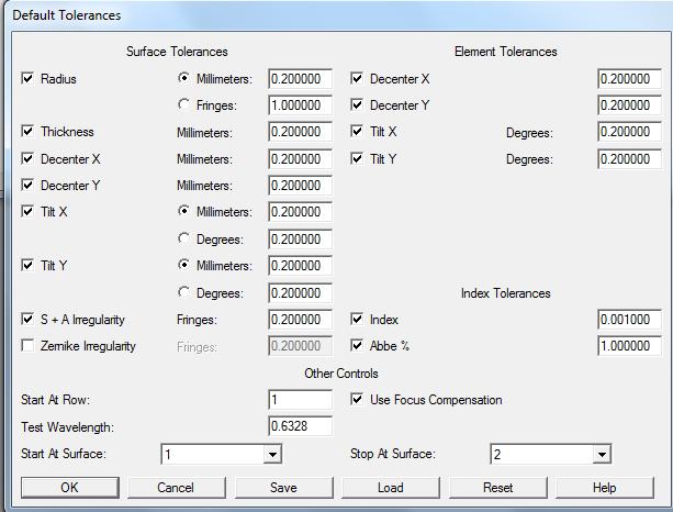

56 Tolerancing in Zemax Tolerance editor
57 Tolerancing in Zemax Specification of tolerances: Operators : TRAD Radius TFRN Number of rings TTHI Thickness TEDX Element decenter x TETX Element tilt x TSDX Flächen decenter x TIRX Flächen tilt x TIRR Surface irregularity TIND Refractive index TABB Abbe number...


58 Tolerancing in Zemax Specifying options: - statistics - model mode - criteria - compensators -...

59 Tolerancing in Zemax Results Sensitivity and total performance


60 Tolerancing in Zemax Graphical overlay of tolerance influence
Lens Design I. Lecture 1: Basics Herbert Gross. Summer term
 Lens Design I Lecture 1: Basics 2015-04-04 Herbert Gross Summer term 2016 www.iap.uni-jena.de 2 Preliminary Schedule 1 04.04. Basics 2 11.04. Properties of optical systems I 3 18.04. 4 25.04. Properties
Lens Design I. Lecture 3: Properties of optical systems II Herbert Gross. Summer term
 Lens Design I Lecture 3: Properties of optical systems II 205-04-27 Herbert Gross Summer term 205 www.iap.uni-jena.de 2 Preliminary Schedule 3.04. Basics 2 20.04. Properties of optical systems I 3 27.05.
Lens Design I. Lecture 4: Properties of optical systems III Herbert Gross. Summer term
 Lens Design I Lecture 4: Properties of optical systems III 018-05-03 Herbert Gross Summer term 018 www.iap.uni-jena.de Preliminary Schedule - Lens Design I 018 1 1.04. Basics 19.04. Properties of optical
Tolerance on material inhomogenity and surface irregularity
 Opti 521 Wenrui Cai Tolerance on material inhomogenity and surface irregularity Abstract In this tutorial, a case study on tolerance for a focusing doublet is performed by using ZEMAX. First, how to perform
Advanced Lens Design
 Advanced Lens Design Lecture 3: Optimization II 2013-10-29 Herbert Gross Winter term 2013 www.iap.uni-jena.de 2 Preliminary Schedule 1 15.10. Introduction Paraxial optics, ideal lenses, optical systems,
Lens Design I. Lecture 11: Imaging Herbert Gross. Summer term
 Lens Design I Lecture 11: Imaging 2015-06-29 Herbert Gross Summer term 2015 www.iap.uni-jena.de 2 Preliminary Schedule 1 13.04. Basics 2 20.04. Properties of optical systrems I 3 27.05. 4 04.05. Properties
Optical Design with Zemax for PhD
 Optical Design with Zemax for PhD Lecture : Physical Optics 06-03-3 Herbert Gross Winter term 05 www.iap.uni-jena.de Preliminary Schedule No Date Subject Detailed content.. Introduction 0.. Basic Zemax
Optical Design with Zemax
 Optical Design with Zemax Lecture 7: Optimization I 2012-12-11 Herbert Gross Winter term 2012 www.iap.uni-jena.de Time schedule 2 1 16.10. Introduction Introduction, Zemax interface, menues, file handling,
Optical Design with Zemax for PhD - Basics
 Optical Design with Zemax for PhD - Basics Lecture 8: Advanced handling 2013-06-27 Herbert Gross Summer term 2013 www.iap.uni-jena.de 2 Preliminary Schedule No Date Subject Detailed content 1 02.05. Introduction
Optical Design with Zemax for PhD
 Optical Design with Zemax for PhD Lecture 6: Optimization I 2016-01-06 Herbert Gross Winter term 2015 www.iap.uni-jena.de 2 Preliminary Schedule No Date Subject Detailed content 1 11.11. Introduction 2
Lens Design I. Lecture 2: Properties of optical systems I Herbert Gross. Summer term
 Lens Design I Lecture 2: Properties of optical systems I 2015-04-20 Herbert Gross Summer term 2015 www.iap.uni-jena.de 2 Preliminary Schedule 1 13.04. Basics 2 20.04. Properties of optical systems I 3
Optical Design with Zemax
 Optical Design with Zemax Lecture 10: Advanced handling II 2014-06-20 Herbert Gross Sommer term 2014 www.iap.uni-jena.de 2 Preliminary Schedule 1 11.04. Introduction 2 25.04. Properties of optical systems
Advanced Lens Design
 Advanced Lens Design Lecture 9: Field flattening 04--6 Herbert Gross Winter term 04 www.iap.uni-ena.de Preliminary Schedule.0. Basics Paraxial optics, imaging, Zemax handling 8.0. Optical systems Optical
Lens Design I. Lecture 9: OptimizationI Herbert Gross. Summer term
 Lens Design I Lecture 9: OptimizationI 2015-06-15 Herbert Gross Summer term 2015 www.iap.uni-jena.de 2 Preliminary Schedule 1 13.04. Basics 2 20.04. Properties of optical systrems I 3 27.05. 4 04.05. Properties
Optical Design with Zemax
 Optical Design with Zemax Lecture 10: Advanced handling 2013-06-28 Herbert Gross Summer term 2013 www.iap.uni-jena.de 2 Preliminary Schedule 1 12.04. Introduction 2 19.04. Properties of optical systems
Metrology and Sensing
 Metrology and Sensing Lecture 11: Measurement of basic system properties 017-01-03 Herbert Gross Winter term 016 www.iap.uni-jena.de Preliminary Schedule No Date Subject Detailed Content 1 18.10. Introduction
Optical Design with Zemax
 Optical Design with Zemax Lecture 9: Advanced handling 2014-06-13 Herbert Gross Sommer term 2014 www.iap.uni-jena.de 2 Preliminary Schedule 1 11.04. Introduction 2 25.04. Properties of optical systems
Lens Design. Craig Olson. Julie Bentley. Field Guide to. John E. Greivenkamp, Series Editor SPIE. SPIE Field Guides. Volume FG27
 Field Guide to Lens Design Julie Bentley Craig Olson SPIE Field Guides Volume FG27 John E. Greivenkamp, Series Editor SPIE PRESS Bellingham,Washington USA vii Glossary of Symbols and Acronyms xi Fundamentals
Introduction. Past Homework solutions Optimization Test Plate fitting Tolerance routine Homework. ECE 4616 Deslis
 Introduction Past Homework solutions Optimization Test Plate fitting Tolerance routine Homework 1 Optimization Optimization is one of the most important features in Zemax. We use optimization to be able
Tutorial Zemax 6: Advanced handling
 Tutorial Zemax 6: Advanced handling 2012-09-25 6 Advanced handling 1 6.1 Multi configuration, universal plot and slider... 1 6.2 Macro for Spot Moments... 6 6.3 Multiconfiguration and folding mirror...
Optical Design with Zemax for PhD
 Optical Design with Zemax for PhD Lecture 8: Advanced handling 2016-01-27 Herbert Gross Winter term 2015 www.iap.uni-jena.de 2 Preliminary Schedule No Date Subject Detailed content 1 11.11. Introduction
Lens Design I. Lecture 2: Properties of optical systems I Herbert Gross. Summer term
 Lens Design I Lecture 2: Properties of optical systems I 2018-04-19 Herbert Gross Summer term 2018 www.iap.uni-jena.de 2 Preliminary Schedule - Lens Design I 2018 1 12.04. Basics 2 19.04. Properties of
Feature Map. Work the way you want, faster, easier... with the same Zemax reliability. RIBBONS / EDITORS
 Feature Map Feature Map Work the way you want, faster, easier... with the same Zemax reliability. Zemax brings a new level of productivity to optics simulation software with OpticStudio14. Built on Zemax
Ray Optics I. Last time, finished EM theory Looked at complex boundary problems TIR: Snell s law complex Metal mirrors: index complex
 Phys 531 Lecture 8 20 September 2005 Ray Optics I Last time, finished EM theory Looked at complex boundary problems TIR: Snell s law complex Metal mirrors: index complex Today shift gears, start applying
Imaging and Aberration Theory
 Imaging and Aberration Theory Lecture 8: Astigmastism and field curvature 03--9 Herbert Gross Winter term 03 www.iap.uni-jena.de Preliminary time schedule 4.0. Paraxial imaging paraxial optics, fundamental
Optical Design with Zemax
 Optical Design with Zemax Lecture 2: Properties of optical systems I 2014-04-18 Herbert Gross Sommer term 2014 www.iap.uni-ena.de 2 Preliminary Schedule 1 11.04. Introduction 2 18.04. Properties of optical
Optical Design with Zemax
 Optical Design with Zemax Lecture 9: Illumination 2013-06-14 Herbert Gross Summer term 2013 www.iap.uni-jena.de 2 Preliminary Schedule 1 12.04. Introduction 2 19.04. Properties of optical systems I 3 26.04.
Imaging and Aberration Theory
 Imaging and Aberration Theory Lecture 8: Astigmatism and field curvature 0--4 Herbert Gross Winter term 0 www.iap.uni-jena.de Preliminary time schedule 9.0. Paraxial imaging paraxial optics, fundamental
OPTI 513R / Optical Testing
 OPTI 513R / Optical Testing Instructor: Dae Wook Kim Meinel Building Rm 633, University of Arizona, Tucson, AZ 85721 E-Mail: dkim@optics.arizona.edu Website: sites.google.com/site/opti513r/ Office Hours:
Chapter 36. Image Formation
 Chapter 36 Image Formation Apr 22, 2012 Light from distant things We learn about a distant thing from the light it generates or redirects. The lenses in our eyes create images of objects our brains can
Metrology and Sensing
 Metrology and Sensing Lecture 4: Fringe projection 2016-11-08 Herbert Gross Winter term 2016 www.iap.uni-jena.de 2 Preliminary Schedule No Date Subject Detailed Content 1 18.10. Introduction Introduction,
Efficient wave-optical calculation of 'bad systems'
 1 Efficient wave-optical calculation of 'bad systems' Norman G. Worku, 2 Prof. Herbert Gross 1,2 25.11.2016 (1) Fraunhofer Institute for Applied Optics and Precision Engineering IOF, Jena, Germany (2)
Diffraction. Single-slit diffraction. Diffraction by a circular aperture. Chapter 38. In the forward direction, the intensity is maximal.
 Diffraction Chapter 38 Huygens construction may be used to find the wave observed on the downstream side of an aperture of any shape. Diffraction The interference pattern encodes the shape as a Fourier
Lens Design II. Lecture 12: Mirror systems Herbert Gross. Winter term
 Lens Design II Lecture 1: Mirror systems 017-01-11 Herbert Gross Winter term 016 www.iap.uni-jena.de Preliminary Schedule 1 19.10. Aberrations and optimization Repetition 6.10. Structural modifications
Coupling of surface roughness to the performance of computer-generated holograms
 Coupling of surface roughness to the performance of computer-generated holograms Ping Zhou* and Jim Burge College of Optical Sciences, University of Arizona, Tucson, Arizona 85721, USA *Corresponding author:
Medical Photonics Lecture Optical Engineering
 Medical Photonics Lecture Optical Engineering Lecture 13: Metrology 2018-02-01 Herbert Gross Winter term 2017 www.iap.uni-jena.de 2 Schedule Optical Engineering 2017 No Subject Ref Date Detailed Content
Geometrical Optics. Chapter General Comments. 1.2 Snell s Law
 Chapter 1 Geometrical Optics 1.1 General Comments A light wave is an electromagnetic wave, and the wavelength that optics studies ranges from the ultraviolet (0.2 mm) to the middle infrared (10 mm). The
Chapter 8: Physical Optics
 Chapter 8: Physical Optics Whether light is a particle or a wave had puzzled physicists for centuries. In this chapter, we only analyze light as a wave using basic optical concepts such as interference
Contrast Optimization: A faster and better technique for optimizing on MTF ABSTRACT Keywords: INTRODUCTION THEORY
 Contrast Optimization: A faster and better technique for optimizing on MTF Ken Moore, Erin Elliott, Mark Nicholson, Chris Normanshire, Shawn Gay, Jade Aiona Zemax, LLC ABSTRACT Our new Contrast Optimization
18.4 Release Notes May 10th, 2018
 18.4 Release Notes May 10 th, 2018 CONTENTS 1 Sequential Features... 3 1.1 Full-Field Aberration analysis (Professional and Premium editions)... 3 1.2 GRIN surface usage with User-Defined and Grid Sag
Metrology and Sensing
 Metrology and Sensing Lecture 4: Fringe projection 2018-11-09 Herbert Gross Winter term 2018 www.iap.uni-jena.de 2 Schedule Optical Metrology and Sensing 2018 No Date Subject Detailed Content 1 16.10.
Null test for a highly paraboloidal mirror
 Null test for a highly paraboloidal mirror Taehee Kim, James H. Burge, Yunwoo Lee, and Sungsik Kim A circular null computer-generated hologram CGH was used to test a highly paraboloidal mirror diameter,
Basic optics. Geometrical optics and images Interference Diffraction Diffraction integral. we use simple models that say a lot! more rigorous approach
 Basic optics Geometrical optics and images Interference Diffraction Diffraction integral we use simple models that say a lot! more rigorous approach Basic optics Geometrical optics and images Interference
Medical Photonics Lecture Optical Engineering
 Medical Photonics Lecture Optical Engineering Lecture 13: Metrology 2018-02-01 Herbert Gross Winter term 2017 www.iap.uni-jena.de 2 Photometric Properties Relations of the 4 main definitions Cassarly's
Lecture 4 Recap of PHYS110-1 lecture Physical Optics - 4 lectures EM spectrum and colour Light sources Interference and diffraction Polarization
 Lecture 4 Recap of PHYS110-1 lecture Physical Optics - 4 lectures EM spectrum and colour Light sources Interference and diffraction Polarization Lens Aberrations - 3 lectures Spherical aberrations Coma,
Fundamental Optics for DVD Pickups. The theory of the geometrical aberration and diffraction limits are introduced for
 Chapter Fundamental Optics for DVD Pickups.1 Introduction to basic optics The theory of the geometrical aberration and diffraction limits are introduced for estimating the focused laser beam spot of a
f. (5.3.1) So, the higher frequency means the lower wavelength. Visible part of light spectrum covers the range of wavelengths from
 So, the higher frequency means the lower wavelength. Visible part of light spectrum covers the range of wavelengths from") Lecture 5-3 Interference and Diffraction of EM Waves During our previous lectures we have been talking about electromagnetic (EM) waves. As we know, harmonic waves of any type represent periodic process
Lecture 5-3 Interference and Diffraction of EM Waves During our previous lectures we have been talking about electromagnetic (EM) waves. As we know, harmonic waves of any type represent periodic process
Chapter 2: Wave Optics
 Chapter : Wave Optics P-1. We can write a plane wave with the z axis taken in the direction of the wave vector k as u(,) r t Acos tkzarg( A) As c /, T 1/ and k / we can rewrite the plane wave as t z u(,)
Final Exam. Today s Review of Optics Polarization Reflection and transmission Linear and circular polarization Stokes parameters/jones calculus
 Physics 42200 Waves & Oscillations Lecture 40 Review Spring 206 Semester Matthew Jones Final Exam Date:Tuesday, May 3 th Time:7:00 to 9:00 pm Room: Phys 2 You can bring one double-sided pages of notes/formulas.
Optical Design with Zemax for PhD - Advanced
 Optical Design with Zemax for PhD - Advanced Seminar 9 : Advanced Topics 2015-02-04 Herbert Gross Winter term 2014 www.iap.uni-jena.de 2 Preliminary Schedule No Date Subject Detailed content 1 12.11. Repetition
Metrology and Sensing
 Metrology and Sensing Lecture 4: Fringe projection 2017-11-09 Herbert Gross Winter term 2017 www.iap.uni-jena.de 2 Preliminary Schedule No Date Subject Detailed Content 1 19.10. Introduction Introduction,
Chapter 7: Geometrical Optics. The branch of physics which studies the properties of light using the ray model of light.
 Chapter 7: Geometrical Optics The branch of physics which studies the properties of light using the ray model of light. Overview Geometrical Optics Spherical Mirror Refraction Thin Lens f u v r and f 2
Waves & Oscillations
 Physics 42200 Waves & Oscillations Lecture 40 Review Spring 2016 Semester Matthew Jones Final Exam Date:Tuesday, May 3 th Time:7:00 to 9:00 pm Room: Phys 112 You can bring one double-sided pages of notes/formulas.
All Reflective Fly s Eye Illuminators for EUV Lithography
 All Reflective Fly s Eye Illuminators for EUV Lithography Blake Crowther, Donald Koch, Joseph Kunick, James McGuire Optical Research Associates Robert Harned, Rick Gontin ASML Presented by Kevin Thompson/
Design and Correction of optical Systems
 Design and Correction of optical Systems Part 3: Components Summer term 0 Herbert Gross Overview. Basics 0-04-8. Materials 0-04-5 3. Components 0-05-0 4. Paraxial optics 0-05-09 5. Properties of optical
Waves & Oscillations
 Physics 42200 Waves & Oscillations Lecture 41 Review Spring 2013 Semester Matthew Jones Final Exam Date:Tuesday, April 30 th Time:1:00 to 3:00 pm Room: Phys 112 You can bring two double-sided pages of
OPTI-521 Graduate Report 2 Matthew Risi Tutorial: Introduction to imaging, and estimate of image quality degradation from optical surfaces
 OPTI-521 Graduate Report 2 Matthew Risi Tutorial: Introduction to imaging, and estimate of image quality degradation from optical surfaces Abstract The purpose of this tutorial is to introduce the concept
Refractive Optical Design Systems Any lens system is a tradeoff of many factors Add optical elements (lens/mirrors) to balance these Many different
 to balance these Many different") Refractive Optical Design Systems Any lens system is a tradeoff of many factors Add optical elements (lens/mirrors) to balance these Many different types of lens systems used Want to look at each from
Refractive Optical Design Systems Any lens system is a tradeoff of many factors Add optical elements (lens/mirrors) to balance these Many different types of lens systems used Want to look at each from
Optical Design with Zemax
 Optical Design with Zemax Lecture 2: Properties of optical systems I 2012-10-23 Herbert Gross Winter term 2012 www.iap.uni-ena.de Preliminary time schedule 2 1 16.10. Introduction Introduction, Zemax interface,
Chapter 38. Diffraction Patterns and Polarization
 Chapter 38 Diffraction Patterns and Polarization Diffraction Light of wavelength comparable to or larger than the width of a slit spreads out in all forward directions upon passing through the slit This
Application-Specific Optical Design
 Application-Specific Optical Design Introduction Optical design software capabilities have advanced considerably from the late 1950s and early 1960s when computer tools first became available. Initially,
Geometric Optics. The Law of Reflection. Physics Waves & Oscillations 3/20/2016. Spring 2016 Semester Matthew Jones
 Physics 42200 Waves & Oscillations Lecture 27 Propagation of Light Hecht, chapter 5 Spring 2016 Semester Matthew Jones Geometric Optics Typical problems in geometric optics: Given an optical system, what
3B SCIENTIFIC PHYSICS
 3B SCIENTIFIC PHYSICS Instruction sheet 06/18 ALF Laser Optics Demonstration Set Laser Optics Supplement Set Page 1 2 3 3 3 4 4 4 5 5 5 6 6 6 7 7 7 8 8 8 9 9 9 10 10 10 11 11 11 12 12 12 13 13 13 14 14
Ray optics! Postulates Optical components GRIN optics Matrix optics
 Ray optics! Postulates Optical components GRIN optics Matrix optics Ray optics! 1. Postulates of ray optics! 2. Simple optical components! 3. Graded index optics! 4. Matrix optics!! From ray optics to
E x Direction of Propagation. y B y
 x E x Direction of Propagation k z z y B y An electromagnetic wave is a travelling wave which has time varying electric and magnetic fields which are perpendicular to each other and the direction of propagation,
Testing spherical surfaces: a fast, quasi-absolute technique
 Testing spherical surfaces: a fast, quasi-absolute technique Katherine Creath and James C. Wyant A technique for measuring the quality of spherical surfaces that provides a quasi-absolute result is presented.
ratio of the volume under the 2D MTF of a lens to the volume under the 2D MTF of a diffraction limited
 SUPPLEMENTARY FIGURES.9 Strehl ratio (a.u.).5 Singlet Doublet 2 Incident angle (degree) 3 Supplementary Figure. Strehl ratio of the singlet and doublet metasurface lenses. Strehl ratio is the ratio of
INFINITY-CORRECTED TUBE LENSES
 INFINITY-CORRECTED TUBE LENSES For use with Infinity-Corrected Objectives Available in Focal Lengths Used by Thorlabs, Nikon, Leica, Olympus, and Zeiss Designs for Widefield and Laser Scanning Applications
Calibration of a portable interferometer for fiber optic connector endface measurements
 Calibration of a portable interferometer for fiber optic connector endface measurements E. Lindmark Ph.D Light Source Reference Mirror Beamsplitter Camera Calibrated parameters Interferometer Interferometer
Geometrical Optics INTRODUCTION. Wave Fronts and Rays
 Geometrical Optics INTRODUCTION In this experiment, the optical characteristics of mirrors, lenses, and prisms will be studied based on using the following physics definitions and relationships plus simple
Highly Efficient Assembly of Lenses with. OptiCentric and OptiCentric Cementing
 Highly Efficient Assembly of Lenses with OptiCentric and OptiCentric Cementing Centration Measurement and Lens Alignment Contents OptiCentric Cementing Centration Measurement and Lens Alignment 3 4 Centration
Section 2. Mirror and Prism Systems
 2-1 Section 2 Mirror and Prism Systems Plane Mirrors Plane mirrors are used to: Produce a deviation Fold the optical path Change the image parity Each ray from the object point obeys the law of reflection
PHYSICS. Chapter 34 Lecture FOR SCIENTISTS AND ENGINEERS A STRATEGIC APPROACH 4/E RANDALL D. KNIGHT
 PHYSICS FOR SCIENTISTS AND ENGINEERS A STRATEGIC APPROACH 4/E Chapter 34 Lecture RANDALL D. KNIGHT Chapter 34 Ray Optics IN THIS CHAPTER, you will learn about and apply the ray model of light Slide 34-2
Optical Design with Zemax
 Optical Design with Zemax Lecture 3: Properties of optical sstems II 04-04-8 Herbert Gross Sommer term 04 www.iap.uni-jena.de Preliminar Schedule.04. Introduction 8.04. Properties of optical sstems I 3
Optical Design with Zemax
 Optical Design with Zemax Lecture : Properties of optical sstems II 0-0-30 Herbert Gross Winter term 0 www.iap.uni-jena.de Properties of Optical Sstems II Preliminar time schedule 6.0. Introduction Introduction,
Chapter 7: Geometrical Optics
 Chapter 7: Geometrical Optics 7. Reflection at a Spherical Surface L.O 7.. State laws of reflection Laws of reflection state: L.O The incident ray, the reflected ray and the normal all lie in the same
A method of evaluating and tolerancing interferometer designs
 A method of evaluating and tolerancing interferometer designs Paul Michaloski, Andrew Kulawiec, Jon Fleig Tropel Corporation 6 O'Connor Road Fairport, New York 1445 Abstract A ray tracing method of simulating
specular diffuse reflection.
 Lesson 8 Light and Optics The Nature of Light Properties of Light: Reflection Refraction Interference Diffraction Polarization Dispersion and Prisms Total Internal Reflection Huygens s Principle The Nature
Paraxial into real surfaces
 Paraxial into real surfaces Curvature, Radius Power lens and mirrors lens maker equation mirror and lens in contact Principle planes Real Surfaces Refractive via Fermat s Principle Calculate optical path
Nicholas J. Giordano. Chapter 24. Geometrical Optics. Marilyn Akins, PhD Broome Community College
 Nicholas J. Giordano www.cengage.com/physics/giordano Chapter 24 Geometrical Optics Marilyn Akins, PhD Broome Community College Optics The study of light is called optics Some highlights in the history
Modern Lens Design. Warren J. Smith Chief Scientist Kaiser Electro-Optics, Inc., Carisbad, California and Consultant in Optics and Design
 Modern Lens Design Warren J. Smith Chief Scientist Kaiser Electro-Optics, Inc., Carisbad, California and Consultant in Optics and Design Second Edition McGraw-Hill New York Chicago San Francisco Lisbon
TEAMS National Competition High School Version Photometry 25 Questions
 TEAMS National Competition High School Version Photometry 25 Questions Page 1 of 14 Telescopes and their Lenses Although telescopes provide us with the extraordinary power to see objects miles away, the
Coherent Gradient Sensing Microscopy: Microinterferometric Technique. for Quantitative Cell Detection
 Coherent Gradient Sensing Microscopy: Microinterferometric Technique for Quantitative Cell Detection Proceedings of the SEM Annual Conference June 7-10, 010 Indianapolis, Indiana USA 010 Society for Experimental
Ray Optics Demonstration Set (RODS) and Ray Optics Demonstration Set Plus (RODS+) USER S GUIDE
 and Ray Optics Demonstration Set Plus (RODS+) USER S GUIDE") Ray Optics Demonstration Set (RODS) and Ray Optics Demonstration Set Plus USER S GUIDE 1 NO. OF EXP. Table of contents TITLE OF EXPERIMENT SET TO USE Introduction Tables of the set elements E1 Reflection
Ray Optics Demonstration Set (RODS) and Ray Optics Demonstration Set Plus USER S GUIDE 1 NO. OF EXP. Table of contents TITLE OF EXPERIMENT SET TO USE Introduction Tables of the set elements E1 Reflection
High spatial resolution measurement of volume holographic gratings
 High spatial resolution measurement of volume holographic gratings Gregory J. Steckman, Frank Havermeyer Ondax, Inc., 8 E. Duarte Rd., Monrovia, CA, USA 9116 ABSTRACT The conventional approach for measuring
Innovations in beam shaping & illumination applications
 Innovations in beam shaping & illumination applications David L. Shealy Department of Physics University of Alabama at Birmingham E-mail: dls@uab.edu Innovation Novelty The introduction of something new
Light & Optical Systems Reflection & Refraction. Notes
 Light & Optical Systems Reflection & Refraction Notes What is light? Light is electromagnetic radiation Ultra-violet + visible + infra-red Behavior of Light Light behaves in 2 ways particles (photons)
How to Use the Luminit LSD Scatter Model
 How to Use the Luminit LSD Scatter Model Summary: This article describes the characteristics and use of Luminit s LSD scatter model in OpticStudio. The scatter model presented here is the idealized scatter
Ray optics! 1. Postulates of ray optics! 2. Simple optical components! 3. Graded index optics! 4. Matrix optics!!
 Ray optics! 1. Postulates of ray optics! 2. Simple optical components! 3. Graded index optics! 4. Matrix optics!! From ray optics to quantum optics! Ray optics! Wave optics! Electromagnetic optics! Quantum
Chapter 24 - The Wave Nature of Light
 Chapter 24 - The Wave Nature of Light Summary Four Consequences of the Wave nature of Light: Diffraction Dispersion Interference Polarization Huygens principle: every point on a wavefront is a source of
( ) = First Bessel function, x = π Dθ
 = First Bessel function, x = π Dθ") Observational Astronomy Image formation Complex Pupil Function (CPF): (3.3.1) CPF = P( r,ϕ )e ( ) ikw r,ϕ P( r,ϕ ) = Transmittance of the aperture (unobscured P = 1, obscured P = 0 ) k = π λ = Wave number
Observational Astronomy Image formation Complex Pupil Function (CPF): (3.3.1) CPF = P( r,ϕ )e ( ) ikw r,ϕ P( r,ϕ ) = Transmittance of the aperture (unobscured P = 1, obscured P = 0 ) k = π λ = Wave number
Lasers PH 645/ OSE 645/ EE 613 Summer 2010 Section 1: T/Th 2:45-4:45 PM Engineering Building 240
 Lasers PH 645/ OSE 645/ EE 613 Summer 2010 Section 1: T/Th 2:45-4:45 PM Engineering Building 240 John D. Williams, Ph.D. Department of Electrical and Computer Engineering 406 Optics Building - UAHuntsville,
AP Physics: Curved Mirrors and Lenses
 The Ray Model of Light Light often travels in straight lines. We represent light using rays, which are straight lines emanating from an object. This is an idealization, but is very useful for geometric
Contrast Optimization A new way to optimize performance Kenneth Moore, Technical Fellow
 Contrast Optimization A new way to optimize performance Kenneth Moore, Technical Fellow What is Contrast Optimization? Contrast Optimization (CO) is a new technique for improving performance of imaging
Meet Your Augmented and Virtual Reality Challenges Head-On: Design Your Next System with 2D-Q Freeforms in CODE V
 WHITE PAPER Meet Your Augmented and Virtual Reality Challenges Head-On: Design Your Next System with 2D-Q Freeforms in CODE V Author Matt Novak, Ph.D. CODE V Sr. Customer Applications Engineer, Synopsys
ENGR142 PHYS 115 Geometrical Optics and Lenses
 ENGR142 PHYS 115 Geometrical Optics and Lenses Part A: Rays of Light Part B: Lenses: Objects, Images, Aberration References Pre-lab reading Serway and Jewett, Chapters 35 and 36. Introduction Optics play
CODE V Optical Design Software. Design, Optimize and Fabricate Reliable Imaging Optics
 CODE V Optical Design Software Design, Optimize and Fabricate Reliable Imaging Optics Overview Using CODE V, ORA engineers played a key role in the design and implementation of all the primary null lenses
OPTI-502 Midterm Exam John E. Greivenkamp Page 1/12 Fall, 2016
 Page 1/12 Fall, 2016 October 19, 2016 Lecture 17 Name SOLUTIONS Closed book; closed notes. Time limit: 75 minutes. An equation sheet is attached and can be removed. A spare raytrace sheet is also attached.
ntermediafe Optical Design
 ntermediafe Optical Design Michael ]. Kidgcr SPIE PRESS A Publication of SPIE The International Society for Optical Engineering Bellingham, Washington USA CONTENTS Foreword Preface List of Symbols xi xv
Chapter 24. Wave Optics. Wave Optics. The wave nature of light is needed to explain various phenomena
 Chapter 24 Wave Optics Wave Optics The wave nature of light is needed to explain various phenomena Interference Diffraction Polarization The particle nature of light was the basis for ray (geometric) optics