Optical Design with Zemax for PhD
|
|
|
- Poppy Wiggins
- 6 years ago
- Views:
Transcription

1 Optical Design with Zemax for PhD Lecture 8: Advanced handling Herbert Gross Winter term
2 2 Preliminary Schedule No Date Subject Detailed content Introduction Basic Zemax handling Properties of optical systems Aberrations I Aberrations II PSF, MTF, ESF Zemax interface, menus, file handling, system description, editors, preferences, updates, system reports, coordinate systems, aperture, field, wavelength, layouts, raytrace, diameters, stop and pupil, solves, ray fans, paraxial optics surface types, quick focus, catalogs, vignetting, footprints, system insertion, scaling, component reversal aspheres, gradient media, gratings and diffractive surfaces, special types of surfaces, telecentricity, ray aiming, afocal systems representations, spot, Seidel, transverse aberration curves, Zernike wave aberrations Optimization I algorithms, merit function, variables, pick up s Optimization II methodology, correction process, special requirements, examples Advanced handling Imaging Fourier imaging, geometrical images Correction I simple and medium examples Correction II advanced examples slider, universal plot, I/O of data, material index fit, multi configuration, macro language Illumination simple illumination calculations, non-sequential option Physical optical modelling Gaussian beams, POP propagation Tolerancing Sensitivities, Tolerancing, Adjustment
3 3 Contents 1. Miscellaneous 2. Vignetting, diameter types, ray aiming 3. Material index fit 4. Lens catalogs 5. Graphical options 6. Slider and visual optimization 7. Multi configuration 8. Data IO 9. Macro language
4 4 Special Infinity Cases Object in infinity - incoming marginal ray parallel to axis - first distance infinity - off-axis field only as angle - no initial NA possible Image in infinity - outgoing marginal ray ideally parallel to axis - explicit declaration: afocal image space - geometrical aberrations as angles - wave aberration reference is plane wave - definition of Airy diameter in mrad Entrance pupil in infinity - incoming chief ray parallel to axis - explicit declaration: telecentric object space Exit pupil in infinity - outgoing chief ray ideally parallel to axis
5 The Special Infinity Cases Simple case: - object, image and pupils are lying in a finite distance - non-telecentric relay systems Special case 1: - object at infinity - object sided afocal - example: camera lens for distant objects Special case 2: - image at infinity - image sided afocal - example: eyepiece Special case 3: - exit pupil at infinity - image side telecentric - example: camera lens for metrology Special case 4: - exit pupil at infinity - image sided telecentric - example: old fashion lithographic lens 5
6 The Special Infinity Cases Very special: combination of above cases Examples: - both sided telecentric: 4f-system, lithographic lens - both sided afocal: afocal zoom - object sided telecentric, image sided afocal: microscopic lens Notice: telecentricity and afocality can not be combined on the same side of a system


7 7 Cardinal Elements in Zemax Cardinal elements of a selected index range (lens or group)

8 8 Quick Focus Option In the menue TOOLS DESIGN QUICK FOCUS we have the opportunity to adjust the image location according to the criteria 1. Spot diameter 2. Wavefront rms 3. Angle radius IN principle, this option is a simplified optimization Example: find the best image plane of a single lens Spot before and after performing the optimal focussing

9 9 Quick Adjust Option In the menue TOOLS DESIGN QUICK ADJUST we have the opportunity to adjust 1. one thickness 2. one radius similar to the quick focus function some where in the system Special application: adjust the air distance before a collimation lens to get the best collimation As criteria, wavefroint, spot diameter of angular radius ar possible Example: Move a lens in between a system to focus the image Spots before and aftre thew adjustment


10 10 System changes Useful commands for system changes: 1. Scaling (e.g. patents) 2. Insert system with other system file File - Insert Lens 2. Reverse system


11 11 3D Geometry Auxiliary menus: 1. Tilt/Decenter element 2. Folding mirror

12 12 3D Geometry Local tilt and decenter of a surface 1. no direct visibility in lens editor only + near surface index 2. input in surface properties 3. with effect on following system surfaces
13 Aperture data in Zemax Different possible options for specification of the aperture in Zemax: 1. Entrance pupil diameter 2. Image space F# 3. Object space NA 4. Paraxial working F# 5. Object cone angle 6. Floating by stop size Stop location: 1. Fixes the chief ray intersection point 2. input not necessary for telecentric object space 3. is used for aperture determination in case of aiming Special cases: 1. Object in infinity (NA, cone angle input impossible) 2. Image in infinity (afocal) 3. Object space telecentric

14 14 Diameters in Zemax There are several different types of diameters in Zemax: 1. Surface stop - defines the axis intersection of the chief ray - usually no influence on aperture size - only one stop in the system - is indicated in the Lens Data Editor by STO - if the initial aperture is defined, the size of the stop semi-diameter is determined by marginal raytrace
 - serves also as drawing size in the layout (for nice layouts) - if the diameter in the stop plane is fixed, the initial aperture can be")
15 15 Diameters in Zemax 2. Userdefined diameter at a surface in the Lens Data Editor (U) - serves also as drawing size in the layout (for nice layouts) - if the diameter in the stop plane is fixed, the initial aperture can be computed automatically by General / Aperture Type / Float by Stop Size This corresponds to a ray aiming 3. Individual diameter of perhaps complicated shape at every surface ( apertures ) - no impact on the drawing - is indicated in the Lens Data Editor by a star - the drawing of vignetted rays can by switched on/off

16 Diameters and stop sizes 4. Individual aperture sizes for every field point can be set by the vignetting factors of the Field menu - real diameters at surfaces must be set - reduces light cones are drawn in the layout VDX, VDY: relative decenter of light cone in x, y VCX, VCY: compressian factors in x, y VAN: azimuthal rotation angle of light cone - If limiting diameters are set in the system, the corresponding factors can be calculated by the Set Vig command 16

17 17 Diameters in Zemax In the Tools-menue, the diameters and apertures can be converted automatically
18 18 Ray Aiming Userdefined diameter at a surface in the Lens Data Editor (U) - serves also as drawing size in the layout (for nice layouts) - if the diameter of the system stop is fixed, the initial aperture can be computed automatically by General / Aperture Type / Float by Stop Size This corresponds to a ray aiming on the rim of the stop surface. The aperture values in the PRESCRIPTION DATA list then changes with the diameter A more general aiming and determination of the opening for all predefined diameters is not possible in Zemax


19 Material Index Fit choice of 4 dispersion formula after fit: - pv and rms of approximation visible - no individual errors seen check results for suitable accuracy, especially at wavelengths and temperatures with sparse input data and at intervall edges add to catalog enter additional data Save catalog Ref.: B. Böhme 19

20 20 Material Index Fit Establishing a special own material Select menue: Tools / Catalogs / Glass catalogs Options: 1. Fit index data 2. Fit melt data Input of data for wavelengths and indices It is possible to establish own material catalogs with additional glasses as an individual library


21 21 Material Index Fit Melt data: - for small differences of real materials - no advantage for new materials Menue option: Glass Fitting Tool don t works (data input?)


22 22 Material Index Fit Menue: Fit Index Data Input of data: 2 options: 1. explicite entering wavelengths and indices 2. load file xxx.dat with two columns: wavelength in mm and index Choice of 4 different dispersion formulas After fit: - pv and rms of approximation visible - no individual errors seen - new material can be added to catalog - data input can be saved to file


23 Lens Catalogs Lens catalogs: Data of commercial lens vendors Searching machine for one vendor Componenets can be loaded or inserted Preview and data prescription possible Special code of components in brackets according to search criteria 23
24 Lens Catalogs Some system with more than one lens available Sometimes: - aspherical constants wrong - hidden data with diameters, wavelengths,... - problems with old glasses Data stored in binary.zmf format Search over all catalogs not possible Catalogs changes dynamically with every release Private catalog can be generated 24
25 Stock Lens Matching This tool swaps out lenses in a design to the nearest equivalent candidate out of a vendor catalogue It works together with the merit function requirements (with constraints) Aspheric, GRIN and toroidal surfaces not supported; only spherical Works for single lenses and achromates Compensation due to thickness adjustments is optional Reverting a lens to optimize (?) Top results are listed Combination of best single lens substitutions is possible. Overall optimization with nonlinear interaction? Ref.: D. Lokanathan


26 Stock Lens Matching Selectioin of some vendors by CNTR SHIFT marking Ref.: D. Lokanathan
27 Stock Lens Matching Output Ref.: D. Lokanathan


28 28 Report Graphic Compact window with 4 or 6 output options can be summarized and defined individually
29 29 Overlay Option In the menue of output windows the option OVERLAY allows for superposing of two or more variations of the output This gives the opportunity to compare various versions Examples: 1. Layout for x- and y-cross section 2. Universal plot for different parameters 3. Delano diagram for different field sizes

30 30 Universal Plot Possibility to generate individual plots for special properties during changing one or two parameters Usually the criteria of the merit function are shown Demonstration: aspherical lens, change of Strehl ratio with values of constants The sensitivity of the correction can be estimated It is seen, that the aspherical constants on one side are enough to correct the system


31 31 Universal Plot One-dimensional: change of 4th order coefficient at first surface Two-dimensional case: dependence on the coefficients on both sides


32 32 Universal Plot Universal plot configurations can be saved and called later Useful example: spot diameter as a function of a variable: operator RSCH


33 33 Slider Slider option in menue: Tools / Miscellaneous / Slider Dependence of chosen window output as a function of a varying parameter Automatic scan or manual adjustment possible Example 1: spot for changing the aspherical constant of 4th order of a lens Example 2: Optical compensated zoom system

34 Visual optimization Menu Tools / Design / Visual optimization Change of variable quantities by slider and instantaneous change of all windows Optimization under visual control of the consequences
35 35 Multi Configuration Multi configuration editor Establishment of different system paths or configurations Toggle between configurations with CNTR A Examples: 1. Zoom systems, lenses moved 2. Scan systems, mirror rotated 3. Switchable optics, components considered / not taken into account 4. Interferometer, test and reference arm 5. Camera with different object distances 6. Microscope tube system for several objective lenses In the multi configuration editor, the parameters / differences must be defined Many output options and the optimization can take all configurations into account Special option: showallconfiguration in the 3D layout drawing simultaneously 1. shifted, for comparison 2. with same reference, overlayed
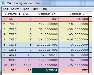
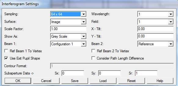
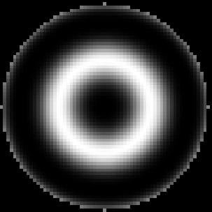
36 36 Multi Configuration Demonstrational example: Twyman-Green interferometer

37 37 Data IO Output of numerical data of results: Text option with save: generation of ASCII file

38 38 Data IO Export of IGES / STEP files, for CAD data transfer


39 39 Macro Language There is a macro language for Zemax to allow for individual problem solving Some provided example files are distributed Editing and running can be done from Zemax interface Necessary: xxx.zmx-file Debugging of macro-language errors is cumbersome Not all of the output data is provided by the commands Coding of parameters is in many cases a bit tricky Graphical options rather limited Possibilities: 1. special and individual analysis 2. change of system data and case studies 3. optimization 4. print export of data
40 40 Macro Language Code Example: Incidence angles at all surfaces for 3 field positions Online output
41 41 Important Macro Commands! comment line follows variables, declarations, simple operations, strings, basic mathematical functions IF THEN ELSE, GOTO, LABEL, FOR NEXT a = AQVAL() numerical aperture ro = CURV(j) surface curvature of surface no. j y = FLDY(j) field size no. j u = RAYL(j) direction cosine of real ray at surface no. j y = RAYY(j) y-value of real ray at surface no. j t = THIC(j) thickness at surface j PRINT text, x,y print text FORMAT 5.3 numerical format of output: 5 places, 3 digits OUTPUT fname.txt declaration of output file for results GETSYSTEMDATA n get special coded (n) data of the system GETZERNIKE maxorder, wave, field, sampling, vector, zerntype, epsilon, reference PWAV n set primary wavelength RAYTRACE hx, hy, px, py, wavelength SURP surface, code, value1, value2 set surface properties SYSP code, value1, value2 set system properties
42 42 Example - 1! H.Gross!! Calculation of the 2nd moments in x-and y-direction of a system spots for all field points! A circular pupil shape is assumed! number of field positions in the data nfield = nfld()!! number of pupil sampling points (fix), arbitrary choice, determines accuracy and run time! npup = 21! look for main wavelength in the data! jwave = pwav()! initialization of increments in field and pupil! dw = 2/(nfield-1) dp = 2/(npup-1)!! determine the index of image surface n = nsur()!! header row in output: nfield npup jwave print " " print "Spot 2nd order moments in my" print " " FORMAT 10.5 PRINT "Fields: ",nfield, " pupil sampling: ",npup," wavelength: ",wavl(jwave) print " "
43 43 Example - 2! !! loop over field points in y-direction: index jy! for jy = 1, nfield, 1 hx = 0 hy = sqrt((jy-1)/(nfield-1))!! !! first loop to calculate the centroid!! initialization of centroids and moments! xc = 0 yc = 0 Mx2 = 0 My2 = 0 Nray = 0!! loop over pupil points: indices kx, ky! for ky = 1, npup, 1 for kx = 1, npup, 1 px = -1+(kx-1)*dp py = -1+(ky-1)*dp
44 44 Example - 3! raytrace raytrace hx, hy, px, py, jwave xp = rayx(n) yp = rayy(n)!! error case for rays outside circular pupil ierr = raye() pr = sqrt(px*px+py*py) if ( pr > 1) then ierr = 1!! summation of 1st order moment to calculate the centroid in x and y if (ierr == 0) Nray = Nray+1 xc = xc + xp yc = yc + yp endif!! end of pupil loop next next!! final calculation of centroid coordinates xc,yc xc = xc / Nray yc = yc / Nray!! second loop over pupil for calculation of moments M2 and M3! indices kx, ky for ky=1, npup, 1 for kx = 1, npup, 1
45 45 Example - 4 px = -1+(kx-1)*dp py = -1+(ky-1)*dp! raytrace raytrace hx, hy, px, py, jwave xp = rayx(n) yp = rayy(n)! error case ierr = raye() pr = sqrt(px*px+py*py) if ( pr > 1) then ierr = 1! summation of moments, scaling from mm into my if (ierr == 0) Mx2 = Mx2 + (xp-xc)*(xp-xc)*1.e6 My2 = My2 + (yp-yc)*(yp-yc)*1.e6 endif! end of pupil loops next next! final calculation of moments for present field location and print of results Mx2 = Mx2 / Nray / My2 = My2 / Nray / !! determine field size Hy = fldy(jy) FORMAT 8.4 PRINT "Field: ",Hy," Nray = ",Nray," centroid xc = ",xc," Mx2 = ",Mx2 PRINT " "," "," centroid yc = ",yc," My2 = ",My2 print " "!! end of field loop next
Optical Design with Zemax
 Optical Design with Zemax Lecture 9: Advanced handling 2014-06-13 Herbert Gross Sommer term 2014 www.iap.uni-jena.de 2 Preliminary Schedule 1 11.04. Introduction 2 25.04. Properties of optical systems
Optical Design with Zemax for PhD - Basics
 Optical Design with Zemax for PhD - Basics Lecture 8: Advanced handling 2013-06-27 Herbert Gross Summer term 2013 www.iap.uni-jena.de 2 Preliminary Schedule No Date Subject Detailed content 1 02.05. Introduction
Optical Design with Zemax
 Optical Design with Zemax Lecture 10: Advanced handling II 2014-06-20 Herbert Gross Sommer term 2014 www.iap.uni-jena.de 2 Preliminary Schedule 1 11.04. Introduction 2 25.04. Properties of optical systems
Optical Design with Zemax
 Optical Design with Zemax Lecture 10: Advanced handling 2013-06-28 Herbert Gross Summer term 2013 www.iap.uni-jena.de 2 Preliminary Schedule 1 12.04. Introduction 2 19.04. Properties of optical systems
Optical Design with Zemax for PhD - Advanced
 Optical Design with Zemax for PhD - Advanced Seminar 9 : Advanced Topics 2015-02-04 Herbert Gross Winter term 2014 www.iap.uni-jena.de 2 Preliminary Schedule No Date Subject Detailed content 1 12.11. Repetition
Tutorial Zemax 6: Advanced handling
 Tutorial Zemax 6: Advanced handling 2012-09-25 6 Advanced handling 1 6.1 Multi configuration, universal plot and slider... 1 6.2 Macro for Spot Moments... 6 6.3 Multiconfiguration and folding mirror...
Lens Design I. Lecture 1: Basics Herbert Gross. Summer term
 Lens Design I Lecture 1: Basics 2015-04-04 Herbert Gross Summer term 2016 www.iap.uni-jena.de 2 Preliminary Schedule 1 04.04. Basics 2 11.04. Properties of optical systems I 3 18.04. 4 25.04. Properties
Lens Design I. Lecture 3: Properties of optical systems II Herbert Gross. Summer term
 Lens Design I Lecture 3: Properties of optical systems II 205-04-27 Herbert Gross Summer term 205 www.iap.uni-jena.de 2 Preliminary Schedule 3.04. Basics 2 20.04. Properties of optical systems I 3 27.05.
Lens Design I. Lecture 2: Properties of optical systems I Herbert Gross. Summer term
 Lens Design I Lecture 2: Properties of optical systems I 2018-04-19 Herbert Gross Summer term 2018 www.iap.uni-jena.de 2 Preliminary Schedule - Lens Design I 2018 1 12.04. Basics 2 19.04. Properties of
Advanced Lens Design
 Advanced Lens Design Lecture 3: Optimization II 2013-10-29 Herbert Gross Winter term 2013 www.iap.uni-jena.de 2 Preliminary Schedule 1 15.10. Introduction Paraxial optics, ideal lenses, optical systems,
Lens Design I. Lecture 4: Properties of optical systems III Herbert Gross. Summer term
 Lens Design I Lecture 4: Properties of optical systems III 018-05-03 Herbert Gross Summer term 018 www.iap.uni-jena.de Preliminary Schedule - Lens Design I 018 1 1.04. Basics 19.04. Properties of optical
Lens Design I. Lecture 11: Imaging Herbert Gross. Summer term
 Lens Design I Lecture 11: Imaging 2015-06-29 Herbert Gross Summer term 2015 www.iap.uni-jena.de 2 Preliminary Schedule 1 13.04. Basics 2 20.04. Properties of optical systrems I 3 27.05. 4 04.05. Properties
Lens Design I. Lecture 2: Properties of optical systems I Herbert Gross. Summer term
 Lens Design I Lecture 2: Properties of optical systems I 2015-04-20 Herbert Gross Summer term 2015 www.iap.uni-jena.de 2 Preliminary Schedule 1 13.04. Basics 2 20.04. Properties of optical systems I 3
Optical Design with Zemax
 Optical Design with Zemax Lecture 7: Optimization I 2012-12-11 Herbert Gross Winter term 2012 www.iap.uni-jena.de Time schedule 2 1 16.10. Introduction Introduction, Zemax interface, menues, file handling,
Optical Design with Zemax for PhD
 Optical Design with Zemax for PhD Lecture 6: Optimization I 2016-01-06 Herbert Gross Winter term 2015 www.iap.uni-jena.de 2 Preliminary Schedule No Date Subject Detailed content 1 11.11. Introduction 2
Optical Design with Zemax for PhD
 Optical Design with Zemax for PhD Lecture : Physical Optics 06-03-3 Herbert Gross Winter term 05 www.iap.uni-jena.de Preliminary Schedule No Date Subject Detailed content.. Introduction 0.. Basic Zemax
Lens Design I. Lecture 9: OptimizationI Herbert Gross. Summer term
 Lens Design I Lecture 9: OptimizationI 2015-06-15 Herbert Gross Summer term 2015 www.iap.uni-jena.de 2 Preliminary Schedule 1 13.04. Basics 2 20.04. Properties of optical systrems I 3 27.05. 4 04.05. Properties
Feature Map. Work the way you want, faster, easier... with the same Zemax reliability. RIBBONS / EDITORS
 Feature Map Feature Map Work the way you want, faster, easier... with the same Zemax reliability. Zemax brings a new level of productivity to optics simulation software with OpticStudio14. Built on Zemax
Optical Design with Zemax
 Optical Design with Zemax Lecture 2: Properties of optical systems I 2014-04-18 Herbert Gross Sommer term 2014 www.iap.uni-ena.de 2 Preliminary Schedule 1 11.04. Introduction 2 18.04. Properties of optical
Advanced Lens Design
 Advanced Lens Design Lecture 9: Field flattening 04--6 Herbert Gross Winter term 04 www.iap.uni-ena.de Preliminary Schedule.0. Basics Paraxial optics, imaging, Zemax handling 8.0. Optical systems Optical
Optical Design with Zemax
 Optical Design with Zemax Lecture 9: Illumination 2013-06-14 Herbert Gross Summer term 2013 www.iap.uni-jena.de 2 Preliminary Schedule 1 12.04. Introduction 2 19.04. Properties of optical systems I 3 26.04.
Lens Design. Craig Olson. Julie Bentley. Field Guide to. John E. Greivenkamp, Series Editor SPIE. SPIE Field Guides. Volume FG27
 Field Guide to Lens Design Julie Bentley Craig Olson SPIE Field Guides Volume FG27 John E. Greivenkamp, Series Editor SPIE PRESS Bellingham,Washington USA vii Glossary of Symbols and Acronyms xi Fundamentals
Ray Tracing. Lens Design OPTI 517. Prof. Jose Sasian
 Ray Tracing Lens Design OPTI 517 Use of rays In optical design In computer graphics In acoustics In art In photography Lens design ray-tracing Ray tracing universe Ray tracing It is important to have
Ray Optics I. Last time, finished EM theory Looked at complex boundary problems TIR: Snell s law complex Metal mirrors: index complex
 Phys 531 Lecture 8 20 September 2005 Ray Optics I Last time, finished EM theory Looked at complex boundary problems TIR: Snell s law complex Metal mirrors: index complex Today shift gears, start applying
Optical Design with Zemax
 Optical Design with Zemax Lecture 2: Properties of optical systems I 2012-10-23 Herbert Gross Winter term 2012 www.iap.uni-ena.de Preliminary time schedule 2 1 16.10. Introduction Introduction, Zemax interface,
Efficient wave-optical calculation of 'bad systems'
 1 Efficient wave-optical calculation of 'bad systems' Norman G. Worku, 2 Prof. Herbert Gross 1,2 25.11.2016 (1) Fraunhofer Institute for Applied Optics and Precision Engineering IOF, Jena, Germany (2)
Section 10. Stops and Pupils
 10-1 Section 10 Stops and Pupils Stops and Pupils The aperture stop is the aperture in the system that limits the bundle of light that propagates through the system from the axial object point. The stop
Imaging and Aberration Theory
 Imaging and Aberration Theory Lecture 8: Astigmastism and field curvature 03--9 Herbert Gross Winter term 03 www.iap.uni-jena.de Preliminary time schedule 4.0. Paraxial imaging paraxial optics, fundamental
18.4 Release Notes May 10th, 2018
 18.4 Release Notes May 10 th, 2018 CONTENTS 1 Sequential Features... 3 1.1 Full-Field Aberration analysis (Professional and Premium editions)... 3 1.2 GRIN surface usage with User-Defined and Grid Sag
Optical Design with Zemax
 Optical Design with Zemax Lecture 3: Properties of optical sstems II 04-04-8 Herbert Gross Sommer term 04 www.iap.uni-jena.de Preliminar Schedule.04. Introduction 8.04. Properties of optical sstems I 3
Imaging and Aberration Theory
 Imaging and Aberration Theory Lecture 8: Astigmatism and field curvature 0--4 Herbert Gross Winter term 0 www.iap.uni-jena.de Preliminary time schedule 9.0. Paraxial imaging paraxial optics, fundamental
Optical Design with Zemax
 Optical Design with Zemax Lecture : Properties of optical sstems II 0-0-30 Herbert Gross Winter term 0 www.iap.uni-jena.de Properties of Optical Sstems II Preliminar time schedule 6.0. Introduction Introduction,
Geometrical Optics. Chapter General Comments. 1.2 Snell s Law
 Chapter 1 Geometrical Optics 1.1 General Comments A light wave is an electromagnetic wave, and the wavelength that optics studies ranges from the ultraviolet (0.2 mm) to the middle infrared (10 mm). The
Fundamental Optics for DVD Pickups. The theory of the geometrical aberration and diffraction limits are introduced for
 Chapter Fundamental Optics for DVD Pickups.1 Introduction to basic optics The theory of the geometrical aberration and diffraction limits are introduced for estimating the focused laser beam spot of a
Getting Started Using ZEMAX
 Getting Started Using ZEMAX Version 2.1 Table of Contents 1 ABOUT THIS GUIDE... 3 2 INSTALLING ZEMAX... 4 2.1 INSTALLING THE KEY DRIVER... 4 2.2 INSTALLING RZ PREREQUISITES... 4 2.3 INSTALLING ZEMAX...
Basic optics. Geometrical optics and images Interference Diffraction Diffraction integral. we use simple models that say a lot! more rigorous approach
 Basic optics Geometrical optics and images Interference Diffraction Diffraction integral we use simple models that say a lot! more rigorous approach Basic optics Geometrical optics and images Interference
Refraction at a single curved spherical surface
 Refraction at a single curved spherical surface This is the beginning of a sequence of classes which will introduce simple and complex lens systems We will start with some terminology which will become
Contrast Optimization: A faster and better technique for optimizing on MTF ABSTRACT Keywords: INTRODUCTION THEORY
 Contrast Optimization: A faster and better technique for optimizing on MTF Ken Moore, Erin Elliott, Mark Nicholson, Chris Normanshire, Shawn Gay, Jade Aiona Zemax, LLC ABSTRACT Our new Contrast Optimization
Optical Design with Zemax
 Optical Design with Zemax Lecture 1: Introduction 2012-07-17 Herbert Gross Summer term 2012 www.iap.uni-ena.de Lecture data 2 Planned dates: 17.07. 24.07. 14.08. 28.08. 11.09. 25.09. 09.10. 23.10. 06.11.
Tolerance on material inhomogenity and surface irregularity
 Opti 521 Wenrui Cai Tolerance on material inhomogenity and surface irregularity Abstract In this tutorial, a case study on tolerance for a focusing doublet is performed by using ZEMAX. First, how to perform
INFINITY-CORRECTED TUBE LENSES
 INFINITY-CORRECTED TUBE LENSES For use with Infinity-Corrected Objectives Available in Focal Lengths Used by Thorlabs, Nikon, Leica, Olympus, and Zeiss Designs for Widefield and Laser Scanning Applications
ntermediafe Optical Design
 ntermediafe Optical Design Michael ]. Kidgcr SPIE PRESS A Publication of SPIE The International Society for Optical Engineering Bellingham, Washington USA CONTENTS Foreword Preface List of Symbols xi xv
Paraxial into real surfaces
 Paraxial into real surfaces Curvature, Radius Power lens and mirrors lens maker equation mirror and lens in contact Principle planes Real Surfaces Refractive via Fermat s Principle Calculate optical path
Meet Your Augmented and Virtual Reality Challenges Head-On: Design Your Next System with 2D-Q Freeforms in CODE V
 WHITE PAPER Meet Your Augmented and Virtual Reality Challenges Head-On: Design Your Next System with 2D-Q Freeforms in CODE V Author Matt Novak, Ph.D. CODE V Sr. Customer Applications Engineer, Synopsys
Null test for a highly paraboloidal mirror
 Null test for a highly paraboloidal mirror Taehee Kim, James H. Burge, Yunwoo Lee, and Sungsik Kim A circular null computer-generated hologram CGH was used to test a highly paraboloidal mirror diameter,
Metrology and Sensing
 Metrology and Sensing Lecture 4: Fringe projection 2016-11-08 Herbert Gross Winter term 2016 www.iap.uni-jena.de 2 Preliminary Schedule No Date Subject Detailed Content 1 18.10. Introduction Introduction,
Application-Specific Optical Design
 Application-Specific Optical Design Introduction Optical design software capabilities have advanced considerably from the late 1950s and early 1960s when computer tools first became available. Initially,
Chapter 3 Geometric Optics
 Chapter 3 Geometric Optics [Reading assignment: Goodman, Fourier Optics, Appendix B Ray Optics The full three dimensional wave equation is: (3.) One solution is E E o ûe i ωt± k r ( ). This is a plane
Aberrations in Holography
 Aberrations in Holography D Padiyar, J Padiyar 1070 Commerce St suite A, San Marcos, CA 92078 dinesh@triple-take.com joy@triple-take.com Abstract. The Seidel aberrations are described as they apply to
Measurement of Highly Parabolic Mirror using Computer Generated Hologram
 Measurement of Highly Parabolic Mirror using Computer Generated Hologram Taehee Kim a, James H. Burge b, Yunwoo Lee c a Digital Media R&D Center, SAMSUNG Electronics Co., Ltd., Suwon city, Kyungki-do,
EE119 Homework 3. Due Monday, February 16, 2009
 EE9 Homework 3 Professor: Jeff Bokor GSI: Julia Zaks Due Monday, February 6, 2009. In class we have discussed that the behavior of an optical system changes when immersed in a liquid. Show that the longitudinal
Introduction. Past Homework solutions Optimization Test Plate fitting Tolerance routine Homework. ECE 4616 Deslis
 Introduction Past Homework solutions Optimization Test Plate fitting Tolerance routine Homework 1 Optimization Optimization is one of the most important features in Zemax. We use optimization to be able
Lens Design II. Lecture 12: Mirror systems Herbert Gross. Winter term
 Lens Design II Lecture 1: Mirror systems 017-01-11 Herbert Gross Winter term 016 www.iap.uni-jena.de Preliminary Schedule 1 19.10. Aberrations and optimization Repetition 6.10. Structural modifications
18.7 Release Notes August 14th, 2018
 18.7 Release Notes August 14 th, 2018 CONTENTS 1 Usability... 3 1.1 Improved Graphic Export (All editions)... 3 1.2 Express View (All editions)... 4 1.3 Zemax File Collector (All editions)... 5 1.4 Pop-out
Part Images Formed by Flat Mirrors. This Chapter. Phys. 281B Geometric Optics. Chapter 2 : Image Formation. Chapter 2: Image Formation
 Phys. 281B Geometric Optics This Chapter 3 Physics Department Yarmouk University 21163 Irbid Jordan 1- Images Formed by Flat Mirrors 2- Images Formed by Spherical Mirrors 3- Images Formed by Refraction
FRED Slit Diffraction Application Note
 FRED Slit Diffraction Application Note The classic problem of diffraction through a slit finds one of its chief applications in spectrometers. The wave nature of these phenomena can be modeled quite accurately
Metrology and Sensing
 Metrology and Sensing Lecture 11: Measurement of basic system properties 017-01-03 Herbert Gross Winter term 016 www.iap.uni-jena.de Preliminary Schedule No Date Subject Detailed Content 1 18.10. Introduction
AP Physics: Curved Mirrors and Lenses
 The Ray Model of Light Light often travels in straight lines. We represent light using rays, which are straight lines emanating from an object. This is an idealization, but is very useful for geometric
Chapter 36. Image Formation
 Chapter 36 Image Formation Apr 22, 2012 Light from distant things We learn about a distant thing from the light it generates or redirects. The lenses in our eyes create images of objects our brains can
PH880 Topics in Physics
 PH880 Topics in Physics Modern Optical Imaging (Fall 2010) The minimum path principle n(x,y,z) Γ Γ has the minimum optical path length, compared to the alternative paths. nxyzdl (,, ) Γ Thelaw of reflection
UNIT VI OPTICS ALL THE POSSIBLE FORMULAE
 58 UNIT VI OPTICS ALL THE POSSIBLE FORMULAE Relation between focal length and radius of curvature of a mirror/lens, f = R/2 Mirror formula: Magnification produced by a mirror: m = - = - Snell s law: 1
Geometric Optics. The Law of Reflection. Physics Waves & Oscillations 3/20/2016. Spring 2016 Semester Matthew Jones
 Physics 42200 Waves & Oscillations Lecture 27 Propagation of Light Hecht, chapter 5 Spring 2016 Semester Matthew Jones Geometric Optics Typical problems in geometric optics: Given an optical system, what
Innovations in beam shaping & illumination applications
 Innovations in beam shaping & illumination applications David L. Shealy Department of Physics University of Alabama at Birmingham E-mail: dls@uab.edu Innovation Novelty The introduction of something new
Preparatory School to the Winter College on Optics in Imaging Science January Selected Topics of Fourier Optics Tutorial
 2222-11 Preparatory School to the Winter College on Optics in Imaging Science 24-28 January 2011 Selected Topics of Fourier Optics Tutorial William T. Rhodes Florida Atlantic University Boca Raton USA
Optical Design with Zemax for PhD
 Optical Design with Zemax for PhD Lecture 3: Tolerancing I 26-4-8 Herbert Gross Winter term 25 / Summer term 26 www.iap.uni-jena.de 2 Preliminary Schedule No Date Subject Detailed content.. Introduction
Figure 1 - Refraction
 Geometrical optics Introduction Refraction When light crosses the interface between two media having different refractive indices (e.g. between water and air) a light ray will appear to change its direction
Metrology and Sensing
 Metrology and Sensing Lecture 4: Fringe projection 2018-11-09 Herbert Gross Winter term 2018 www.iap.uni-jena.de 2 Schedule Optical Metrology and Sensing 2018 No Date Subject Detailed Content 1 16.10.
Lecture 4 Recap of PHYS110-1 lecture Physical Optics - 4 lectures EM spectrum and colour Light sources Interference and diffraction Polarization
 Lecture 4 Recap of PHYS110-1 lecture Physical Optics - 4 lectures EM spectrum and colour Light sources Interference and diffraction Polarization Lens Aberrations - 3 lectures Spherical aberrations Coma,
3B SCIENTIFIC PHYSICS
 3B SCIENTIFIC PHYSICS Instruction sheet 06/18 ALF Laser Optics Demonstration Set Laser Optics Supplement Set Page 1 2 3 3 3 4 4 4 5 5 5 6 6 6 7 7 7 8 8 8 9 9 9 10 10 10 11 11 11 12 12 12 13 13 13 14 14
Optics II. Reflection and Mirrors
 Optics II Reflection and Mirrors Geometric Optics Using a Ray Approximation Light travels in a straight-line path in a homogeneous medium until it encounters a boundary between two different media The
Final Exam. Today s Review of Optics Polarization Reflection and transmission Linear and circular polarization Stokes parameters/jones calculus
 Physics 42200 Waves & Oscillations Lecture 40 Review Spring 206 Semester Matthew Jones Final Exam Date:Tuesday, May 3 th Time:7:00 to 9:00 pm Room: Phys 2 You can bring one double-sided pages of notes/formulas.
Advanced Lens Design
 Advanced Lens Design Lecture : Introduction 3--5 Herbert Gross Winter term 3 www.iap.uni-jena.de Overview Time: Tuesday, 8.5 9.45 Location: PaPool, Helmholtweg 4 Web page on IAP homepage under learning/materials
1. INTRODUCTION ABSTRACT
 Copyright 2008, Society of Photo-Optical Instrumentation Engineers (SPIE). This paper was published in the proceedings of the August 2008 SPIE Annual Meeting and is made available as an electronic preprint
Waves & Oscillations
 Physics 42200 Waves & Oscillations Lecture 40 Review Spring 2016 Semester Matthew Jones Final Exam Date:Tuesday, May 3 th Time:7:00 to 9:00 pm Room: Phys 112 You can bring one double-sided pages of notes/formulas.
Optical design of COrE+
 Optical design of COrE+ Karl Young November 23, 2015 The optical designs for COrE+ were made by Darragh McCarthy and Neil Trappe at Maynooth University and Karl Young and Shaul Hanany at University of
Section 2. Mirror and Prism Systems
 2-1 Section 2 Mirror and Prism Systems Plane Mirrors Plane mirrors are used to: Produce a deviation Fold the optical path Change the image parity Each ray from the object point obeys the law of reflection
DESIGN AND ANALYSIS OF DIFFRACTIVE ASPHERIC NULLS
 DESIGN AND ANALYSIS OF DIFFRACTIVE ASPHERIC NULLS Steven M. Arnold Diffraction International, Minnetonka, MN Diffraction International has developed a general methodology for designing diffractive aspheric
Virtual and Mixed Reality > Near-Eye Displays. Simulation of Waveguide System containing a Complex 2D Exit Pupil Expansion
 Virtual and Mixed Reality > Near-Eye Displays Simulation of Waveguide System containing a Complex 2D Exit Pupil Expansion Task/System Illustration? intensity at output of waveguide eye model? intensity
annual report 2011 / 2012 INSTITUT FÜR TECHNISCHE OPTIK UNIVERSITÄT STUTTGART
 annual report 2011 / 2012 INSTITUT FÜR TECHNISCHE OPTIK UNIVERSITÄT STUTTGART INSTITUT FÜR TECHNISCHE OPTIK UNIVERSITÄT STUTTGART Prof. Dr. W. Osten Pfaffenwaldring 9 D-70569 Stuttgart Tel.: +49(0)711
CODE V Optical Design Software. Design, Optimize and Fabricate Reliable Imaging Optics
 CODE V Optical Design Software Design, Optimize and Fabricate Reliable Imaging Optics Overview Using CODE V, ORA engineers played a key role in the design and implementation of all the primary null lenses
Nicholas J. Giordano. Chapter 24. Geometrical Optics. Marilyn Akins, PhD Broome Community College
 Nicholas J. Giordano www.cengage.com/physics/giordano Chapter 24 Geometrical Optics Marilyn Akins, PhD Broome Community College Optics The study of light is called optics Some highlights in the history
Exercise 12 Geometrical and Technical Optics WS 2013/2014
 Exercise 12 Geometrical and Technical Optics WS 213/214 Slide projector and Köhler illumination In this exercise a simplified slide projector (or LCD projector) will be designed and simulated with ray
Metrology and Sensing
 Metrology and Sensing Lecture 4: Fringe projection 2017-11-09 Herbert Gross Winter term 2017 www.iap.uni-jena.de 2 Preliminary Schedule No Date Subject Detailed Content 1 19.10. Introduction Introduction,
Medical Photonics Lecture Optical Engineering
 Medical Photonics Lecture Optical Engineering Lecture 13: Metrology 2018-02-01 Herbert Gross Winter term 2017 www.iap.uni-jena.de 2 Schedule Optical Engineering 2017 No Subject Ref Date Detailed Content
Waves & Oscillations
 Physics 42200 Waves & Oscillations Lecture 41 Review Spring 2013 Semester Matthew Jones Final Exam Date:Tuesday, April 30 th Time:1:00 to 3:00 pm Room: Phys 112 You can bring two double-sided pages of
axis, and wavelength tuning is achieved by translating the grating along a scan direction parallel to the x
 Exponential-Grating Monochromator Kenneth C. Johnson, October 0, 08 Abstract A monochromator optical design is described, which comprises a grazing-incidence reflection and two grazing-incidence mirrors,
Ray Optics Demonstration Set (RODS) and Ray Optics Demonstration Set Plus (RODS+) USER S GUIDE
 and Ray Optics Demonstration Set Plus (RODS+) USER S GUIDE") Ray Optics Demonstration Set (RODS) and Ray Optics Demonstration Set Plus USER S GUIDE 1 NO. OF EXP. Table of contents TITLE OF EXPERIMENT SET TO USE Introduction Tables of the set elements E1 Reflection
Ray Optics Demonstration Set (RODS) and Ray Optics Demonstration Set Plus USER S GUIDE 1 NO. OF EXP. Table of contents TITLE OF EXPERIMENT SET TO USE Introduction Tables of the set elements E1 Reflection
Medical Photonics Lecture 1.2 Optical Engineering
 Medical Photonics Lecture 1.2 Optical Engineering Lecture 4: Components 2017-11-16 Michael Kempe Winter term 2017 www.iap.uni-jena.de 2 Contents No Subject Ref Detailed Content 1 Introduction Gross Materials,
Medical Photonics Lecture Optical Engineering
 Medical Photonics Lecture Optical Engineering Lecture 13: Metrology 2018-02-01 Herbert Gross Winter term 2017 www.iap.uni-jena.de 2 Photometric Properties Relations of the 4 main definitions Cassarly's
Practical Use of Saddle-Point Construction in Lens Design
 Practical Use of Saddle-Point Construction in Lens Design Zhe Hou a, Irina Livshits b, and Florian Bociort a a Optics Research Group, Delft University of Technology, Lorentzweg 1, 2628CJ Delft, The Netherlands;
4. Recommended alignment procedure:
 4. Recommended alignment procedure: 4.1 Introduction The described below procedure presents an example of alignment of beam shapers Shaper and Focal- Shaper (F- Shaper) with using the standard Shaper Mount
Refractive Optical Design Systems Any lens system is a tradeoff of many factors Add optical elements (lens/mirrors) to balance these Many different
 to balance these Many different") Refractive Optical Design Systems Any lens system is a tradeoff of many factors Add optical elements (lens/mirrors) to balance these Many different types of lens systems used Want to look at each from
Refractive Optical Design Systems Any lens system is a tradeoff of many factors Add optical elements (lens/mirrors) to balance these Many different types of lens systems used Want to look at each from
OPTI-502 Optical Design and Instrumentation I John E. Greivenkamp Final Exam In Class Page 1/12 Fall, 2017
 Final Exam In Class Page / Fall, 07 Name SOLUTIONS Closed book; closed notes. Time limit: 0 minutes. An equation sheet is attached and can be removed. Spare raytrace sheets are attached. Use the back sides
New Features in CODE V Version 10
 Webinar Series New Features in CODE V Version 10 3280 East Foothill Boulevard Pasadena, California 91107 USA (626) 795-9101 Fax (626) 795-0184 e-mail: service@opticalres.com World Wide Web: http://www.opticalres.com
Berechnung von Freiformächen für Strahlformung
 Berechnung von Freiformächen für Strahlformung Christoph Bösel 1, Herbert Gross 1,2 1 Friedrich-Schiller-Universität Jena, Institute of Applied Physics, Abbe Center of Photonics, 07743 Jena, Germany 2
Refractive Optical Design Systems Any lens system is a tradeoff of many factors Add optical elements (lens/mirrors) to balance these Many different
 to balance these Many different") Refractive Optical Design Systems Any lens system is a tradeoff of many factors Add optical elements (lens/mirrors) to balance these Many different types of lens systems used Want to look at each from
Refractive Optical Design Systems Any lens system is a tradeoff of many factors Add optical elements (lens/mirrors) to balance these Many different types of lens systems used Want to look at each from
Generalization of the Coddington Equations to Include Hybrid Diffractive Surfaces
 Generalization of the oddington Equations to Include Hybrid Diffractive Surfaces hunyu Zhao* and James H. Burge ollege of Optical Sciences University of Arizona Tucson, AZ USA 857 ABSTRAT oddington Equations
PHYS 219 General Physics: Electricity, Light and Modern Physics
 PHYS 219 General Physics: Electricity, Light and Modern Physics Exam 2 is scheduled on Tuesday, March 26 @ 8 10 PM In Physics 114 It will cover four Chapters 21, 22, 23, and 24. Start reviewing lecture
Modern Lens Design. Warren J. Smith Chief Scientist Kaiser Electro-Optics, Inc., Carisbad, California and Consultant in Optics and Design
 Modern Lens Design Warren J. Smith Chief Scientist Kaiser Electro-Optics, Inc., Carisbad, California and Consultant in Optics and Design Second Edition McGraw-Hill New York Chicago San Francisco Lisbon
INTRODUCTION REFLECTION AND REFRACTION AT BOUNDARIES. Introduction. Reflection and refraction at boundaries. Reflection at a single surface
 Chapter 8 GEOMETRICAL OPTICS Introduction Reflection and refraction at boundaries. Reflection at a single surface Refraction at a single boundary Dispersion Summary INTRODUCTION It has been shown that