Medical Photonics Lecture 1.2 Optical Engineering
|
|
|
- Florence Bishop
- 5 years ago
- Views:
Transcription
1 Medical Photonics Lecture 1.2 Optical Engineering Lecture 4: Components Michael Kempe Winter term
2 2 Contents No Subject Ref Detailed Content 1 Introduction Gross Materials, dispersion, ray picture, geometrical approach, paraxial approximation 2 Geometrical optics Gross Ray tracing, matrix approach, aberrations, imaging, Lagrange invariant 3 Diffraction Gross Basic phenomena, wave optics, interference, diffraction calculation, point spread function, transfer function 4 Components Kempe Lenses, micro-optics, mirrors, prisms, gratings, fibers 5 Optical systems Gross Field, aperture, pupil, magnification, infinity cases, lens makers formula, etendue, vignetting 6 Aberrations Gross Introduction, primary aberrations, miscellaneous 7 Image quality Gross Spot, ray aberration curves, PSF and MTF, criteria 8 Instruments I Kempe Human eye, loupe, eyepieces, photographic lenses, zoom lenses, telescopes 9 Instruments II Kempe Microscopic systems, micro objectives, illumination, scanning microscopes, contrasts 10 Instruments III Kempe Medical optical systems, endoscopes, ophthalmic devices, surgical microscopes 11 Optic design Gross Aberration correction, system layouts, optimization, realization aspects 12 Photometry Gross Notations, fundamental laws, Lambert source, radiative transfer, photometry of optical systems, color theory 13 Illumination systems Gross Light sources, basic systems, quality criteria, nonsequential raytrace 14 Metrology Gross Measurement of basic parameters, quality measurements
 tangential flat stop F P B T S F' P S B T stop C C Reflection Mirrors virtual object location R R/2 R F F' c) best image flat d) sagittal flat 0.")

3 3 Passive Components in Optical Systems 1 from infinity Refraction Lenses F F' real image Beam Shaping Diffraction DOE Reflection Mirrors virtual image a) astigmatism A = 0 b) tangential flat stop F P B T S F' P S B T stop C C Reflection Mirrors virtual object location R R/2 R F F' c) best image flat d) sagittal flat 0.42 R P S B T stop P S B T Wavefront Management Beam Redirection / Splitting Refraction Prisms C R C R stop 0.29 R refractive : one direction diffractive blazed : one direction diffractive binary : all directions Diffraction Gratings +2. order +1. order 0. order -1. order n g g -2. order Beam Guiding Refraction Reflection Graded-Index Fibers Step-Index Fibers


4 4 Passive Components in Optical Systems Refraction Prisms grating +3. diffraction orders +2. Angular Dispersion weiß D incident collimated light rot Diffraction Gratings grün blau g = 1 / s grating constant Wavelength Management Filtering Absorption Absorption Filters Interference Interference and Dielectric Filters Modification Nonlinear Interaction Nonlinear Crystals Angular Dispersion Birefringence Birefringent Prisms etc. Absorption Dichroic Filters Polarisation Management Filtering Reflection Brewster Angle Polarizer Wavefront Retarder / Rotator Modification Birefringence Waveplates
5 virtual object 5 Lenses in Optical Systems Lenses are key elements in optical systems for Optical imaging Optical projection Light focusing (energy concentration) from infinity F F' real image virtual image Virtuell F F' virtual image F F'
6 6 Imaging by Lenses y F F' y' f f s s' y F y' F' s f f s' Lens equation (paraxial approximation, n = n ): 1 s 1 s = 1 f = 1 f Magnification: m = y = s = f s y s f
7 7 Cardinal Elements of a Refractive Lens Focal points: 1. incoming ray parallel to the axis intersects the axis in F 2. ray through F is leaves the lens parallel to the axis The focal lengths are referenced on the principal planes F front focal plane f P P' f ' F' back focal plane principal planes s BFL nodal planes Nodal points: Ray through N goes through N and preserves the direction N N' u' u
8 Notations of a lens P principal point N nodal point O n n n 1 2 y S vertex of the surface u F N N' S' u' F' F focal point S P P' f focal length PF y' O' r radius of surface curvature r > 0 : center of curvature is located on the right side s a f BFL f s P d s' P' f' f' BFL a' s' c curvature (c=1/r) d thickness SS Optical power F-Number n refractive index n f n' f ' F# = f D D: effective diameter
9 Lens shape Different shapes of singlet lenses: 1. bi-convex/concave, symmetric 2. plane convex / concave, one surface plane 3. Meniscus, both surface radii with the same sign Convex: bending outside Concave: hollow surface Principal planes P, P : outside for meniscus shaped lenses P P' P P' P P' P P' P P' P P' bi-convex lens plane-convex lens positive meniscus lens bi-concave lens plane-concave lens negative meniscus lens

10 Spherical Lenses Exhibit Aberrations Example: spherical aberration
11 Aspheres - Geometry Reference: deviation from sphere Deviation Dz along axis Better conditions: normal deviation Dr s y z(y) deviation Dz y height y tangente z(y) deviation Dz along axis z height y sphere perpendicular deviation Dr s aspherical shape spherical surface z aspherical contour
12 Reducing the Number of Lenses with Aspheres Example photographic zoom lens Equivalent performance 9 lenses reduced to 6 lenses Overall length reduced x x Photographic lens f = 53 mm, F# = 6.5 a) all spherical, 9 lenses Dy axis field 22 Dx Dy Dx 436 nm 588 nm 656 nm y p x p y p x p b) 3 aspheres, 6 lenses, shorter, better performance Dy axis field 22 Dx Dy Dx A 1 A 3 A 2 y p x p y p x p Ref: H. Zügge
13 GRIN lenses Gradient index (GRIN) lenses are using a spatially varying index of refraction Example: GRIN lenses with radial parabolic index profile 0.25 Pitch Object at infinity n r n = n 0 n 2 r² n Pitch Object at front surface r 0.75 Pitch Object at infinity 1.0 Pitch Object at front surface Pitch Such lenses are used, e.g., as relay lenses

14 Fresnel Lenses Fresnel lenses are refractive lenses with a surface structure They are used to reduce weight and length of optical systems active surfaces linear Significant aberrations used for illumination
15 Diffractive Optical Elements Diffractive optical elements (DOE s) are based on diffraction to redirect light refractive : one direction diffractive blazed : one direction diffractive binary : all directions +2. order +1. order 0. order -1. order n g g -2. order Different types: Fresnel zone plates (transmission or phase zones) Binary diffractive elements Computer generated diffractive elements Blazed diffractive element
16 Grating Diffraction Maximum intensity: constructive interference of the contributions of all periods grating Grating equation g sin sin m o grating constant g in-phase + 1. diffraction order Ds = incident light
17 DOE s for Chromatic Correction Example: blazed diffractive element For 1st order r k = 2π f λ k sinψ k = sinθ k n sinθ k = λ r k+1 r k One use of DOE s in optical systems is for color correction


18 Micro Lens Array Used for spot array generation or beam homogenization Ref: W. Osten
:20968-78 September")
19 Use of Micro Lens Arrays for Illumination The aperture splitting of the lens array provides a plurality of parallel Köhler illumination systems Optics Express 18(20): September 2010
20 20 Mirrors Mirrors are based on reflection, typically off coated surfaces (dielectric/metal) The reflectivity but not the direction depend on the wavelength and polarization a) s-polarization b) p-polarization reflection E r B r E r reflection transmission B r transmission E t B t i i' B t i i' E t normal to the interface i normal to the interface i incidence E i B i n n' incidence interface B i E i n n' interface Reflectivity of silver In optical systems mirrors are used to redirect light and to control aberrations

 best image flat d) sagittal flat P S B T P")
21 21 Curved Spherical Mirrors Radius of curvature R Focal length R/2 On-axis imaging with spherical aberration Strong aberrations off-axis dependent on pupil stop position a) astigmatism A = 0 b) tangential flat stop Image P B Tplane S P S B C C R R/2 R c) best image flat d) sagittal flat P S B T P stop
 0 > > - 1 prolate ellipsoid (cigar ) y x")
22 22 Aspheric Surface: Conic Sections Explicite surface equation, resolved to z Parameters: curvature c = 1 / R conic parameter z 2 2 cx y c x 1 1 y Influence of on the surface shape z Parameter Surface shape = - 1 paraboloid < - 1 hyperboloid = 0 sphere > 0 oblate ellipsoid (disc) 0 > > - 1 prolate ellipsoid (cigar ) y x
23 Simple Asphere Parabolic Mirror Surface equation z x 2 2 R s y 2 Radius of curvature in vertex: R s Perfect imaging on axis for object at infinity Strong coma aberration for finite field angles Applications: 1. Astronomical telescopes 2. Collector in illumination systems axis w = 0 field w = 2 field w = 4
24 Simple Asphere Elliptical Mirror Equation z 1 Radius of curvature r in vertex, curvature c eccentricity Two different shapes: oblate / prolate Perfect imaging on axis for finite object and image loaction Different magnifications depending on used part of the mirror Applications: Illumination systems s c( x 2 y 2 1 (1 )( x s' ) 2 y 2 ) c 2 F F'

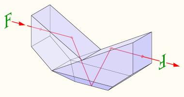
25 Reflection Prisms Right angle prism 90 deflection Bauernfeind prism Beam deviation Penta prism 90 deflection Rhomboid prism Beam offset Dove prism image inversion
26 Properties of Reflection Prisms Functions 1. Bending of the beam path, deflection of the axial ray direction Application in instrumental optics and folded ray paths 2. Parallel off-set, lateral displacement of the axial ray 3. Modification of the image orientation (reversion, inversion) 4. Off-set of the image position, shift of image position forwards in the propagation direction. Aberrations introduced 1. Astigmatism 2. Chromatic aberration 3. Spherical aberration in non-collimated beams
27 Transformation of Image Orientation image reversion in the folding plane (upside down) image unchanged original Modification of the image orientation with four options: 1. Invariant image orientation 2. Reverted image ( side reversal ) 3. Reverted image ( upside down ) 4. Image inversion y image reversion perpendicular to the folding plane folding plane image inversion x mirror 1 y - z- folding plane y mirror 2 y x z x z
28 Transform of Image Orientation Rotatable Dove prism: Azimutal angle: image rotates by the double angle object angle of prism rotation Bild angle of image rotation Application: periscopes


29 Application in Binoculars Double Porro Prism Abbe-König Roof Prism
30 Conical Light Taper Waveguide with conical boundary Lagrange invariant: decrease in diameter causes increase in angle: Aperture transformed D sin u D sin u' Number of reflections: - depends on diameter/length ratio - defines change of aperture angle in out D in / 2 Reflexion No j u' D out / 2 u r i n n L
31 31 Optical Fibers: Step-Index total Totalreflexion r refractive Brechzahlindex cladding Mantel a i core Kern z 1 n 2 n 1 n Index step Critical angle Numerical aperture = n 1 n 2 n 1 = θ c = cos 1 (n 2 /n 1 ) NA = sin θ a = n 1 sin θ c = n 1 ² n 2 ² θ a : acceptance angle
32 32 Optical Fibers: Step-Index V fiber parameter descibes number of guided modes 2 a V NA Number of modes: Requirement for single mode : V E(r) M V² 2 Approximation for fundamental mode: Gaussian beam 1 rule-of-thumb for width: w e a V 0.5 V = 3.0 V = 1.0 V = 2.2 V = r / a
33 Radial Index 33 Fundamental Mode of Step-Index Fibers Scalar solution of mode propagation with step-index boundary condition : Core : r < a E( r,, z) A J ( kr) e m im e iz Cladding : r > a E( r,, z) B K ( kr) e m im Mode matching is requirement for efficient in- and out-coupling A(r) Grundmode fundamental mode J 0 (kr) Anregungsmode J 3 (kr) K 0 (gr) K 3 (gr) r Kern core cladding Mantel Azimutal Index
34 34 Optical Fibers: Graded-Index Continuous index profile in core Rays follow curved trajectories with shorter paths compared to step-index fibers Number of modes: M V² 4 kontinuierliche continuous ray deflection Strahlbiegung r refractive Brechzahlindex cladding Mantel a Kern core z 1 n 2 n 1 n
35 Dispersion Prism Dispersion prism spatially separate light in its colors Blue light is refracted more strongly than red light ( normal dispersion) Application : spectrometer, dispersion control white weiß α For symmetric case D 2 arcsin n sin 2 dφ dλ = rot grün red blau green blue 2sin α/2 1 n 2 sin² α/2 dn dλ
36 Ideal Diffraction Grating Ideal diffraction grating: monochromatic incident collimated beam is decomposed into discrete sharp diffraction orders blue grating red Constructive interference of the contributions of all periodic cells Only two orders for sinusoidal grating constant g blue in-phase + 1. diffraction order sin sin m o / g Ds = incident light
37 Grating Equation Intensity of grating diffraction pattern Product of slit-diffraction and interference function Maxima of pattern: coincidence of peaks of both functions: grating equation g sin sin m Angle spread of an order decreases with growing number od periods N Oblique phase gradient: - relative shift of both functions - selection of peaks/order - basic principle of blazing o I N s g 2 g 2 us Nug sin sin us ug N sin slit diffraction 2 interference function u = λ g u = λ s u = sin u s λ
38 Spectral Resolution of a Grating Angle dispersion of a grating d D d sin m sin 0 cos Separation of two spectral lines sin m sin 0 A L m N D m I(x) Complete setup with all orders: Overlap of spectra possible at higher orders 0 m /g D m(d /g sin
39 Blaze Grating Blaze grating (echelette): - facets with finite slope - additional phase shifts the slit diffraction function - all orders but one suppressed Blaze condition is only valid for - one wavelength - one incidence angle ψ = θ + θ 0 2 λ = 2g m B sin ψ cos θ 0 ψ slit diffraction working order suppressed orders m B -2 m B -1 m B m B +1 m B +2


40 40 Color Glass Filter Wavelength filtering based on selective absorption of light Insensitive to angle of incidence Heating due to absorption Limited efficiency Neutral density Bandpass Long Pass Short Pass Source: Schott AG
41 41 Dielectric Filters Wavelength filtering based on interference in multilayer systems E R0 E R1 E R2 Sensitive to angle of incidence Low absorption High efficiency n 0 Luft Air Design degrees of freedom increase with number of layers n 1 n 2 d 1 d 2 Layer 1 Layer 2 Example: Anti-reflexion coating For normal incidence Interference Condition n d 1 1 n2d2 / 4 n s Substrate Substrat Amplitude Condition n1 n 2 n n o s E T0
 2 1 R 2R cos")
42 42 Interference Filters Wavelength filtering based on multi-path interference Highly sensitive to angle of incidence Low absorption Low efficiency High wavelength selection T R = R = R = R = R = d φ n Semi-reflective surface λ = d 2n cos φ I T 2 (1 R) 2 1 R 2R cos
Design and Correction of optical Systems
 Design and Correction of optical Systems Part 3: Components Summer term 0 Herbert Gross Overview. Basics 0-04-8. Materials 0-04-5 3. Components 0-05-0 4. Paraxial optics 0-05-09 5. Properties of optical
Lens Design I. Lecture 4: Properties of optical systems III Herbert Gross. Summer term
 Lens Design I Lecture 4: Properties of optical systems III 018-05-03 Herbert Gross Summer term 018 www.iap.uni-jena.de Preliminary Schedule - Lens Design I 018 1 1.04. Basics 19.04. Properties of optical
Lens Design I. Lecture 3: Properties of optical systems II Herbert Gross. Summer term
 Lens Design I Lecture 3: Properties of optical systems II 205-04-27 Herbert Gross Summer term 205 www.iap.uni-jena.de 2 Preliminary Schedule 3.04. Basics 2 20.04. Properties of optical systems I 3 27.05.
Lens Design I. Lecture 11: Imaging Herbert Gross. Summer term
 Lens Design I Lecture 11: Imaging 2015-06-29 Herbert Gross Summer term 2015 www.iap.uni-jena.de 2 Preliminary Schedule 1 13.04. Basics 2 20.04. Properties of optical systrems I 3 27.05. 4 04.05. Properties
Lens Design I. Lecture 1: Basics Herbert Gross. Summer term
 Lens Design I Lecture 1: Basics 2015-04-04 Herbert Gross Summer term 2016 www.iap.uni-jena.de 2 Preliminary Schedule 1 04.04. Basics 2 11.04. Properties of optical systems I 3 18.04. 4 25.04. Properties
UNIT VI OPTICS ALL THE POSSIBLE FORMULAE
 58 UNIT VI OPTICS ALL THE POSSIBLE FORMULAE Relation between focal length and radius of curvature of a mirror/lens, f = R/2 Mirror formula: Magnification produced by a mirror: m = - = - Snell s law: 1
Lecture 4 Recap of PHYS110-1 lecture Physical Optics - 4 lectures EM spectrum and colour Light sources Interference and diffraction Polarization
 Lecture 4 Recap of PHYS110-1 lecture Physical Optics - 4 lectures EM spectrum and colour Light sources Interference and diffraction Polarization Lens Aberrations - 3 lectures Spherical aberrations Coma,
Ray Optics I. Last time, finished EM theory Looked at complex boundary problems TIR: Snell s law complex Metal mirrors: index complex
 Phys 531 Lecture 8 20 September 2005 Ray Optics I Last time, finished EM theory Looked at complex boundary problems TIR: Snell s law complex Metal mirrors: index complex Today shift gears, start applying
Ray optics! Postulates Optical components GRIN optics Matrix optics
 Ray optics! Postulates Optical components GRIN optics Matrix optics Ray optics! 1. Postulates of ray optics! 2. Simple optical components! 3. Graded index optics! 4. Matrix optics!! From ray optics to
Advanced Lens Design
 Advanced Lens Design Lecture 9: Field flattening 04--6 Herbert Gross Winter term 04 www.iap.uni-ena.de Preliminary Schedule.0. Basics Paraxial optics, imaging, Zemax handling 8.0. Optical systems Optical
Diffraction. Single-slit diffraction. Diffraction by a circular aperture. Chapter 38. In the forward direction, the intensity is maximal.
 Diffraction Chapter 38 Huygens construction may be used to find the wave observed on the downstream side of an aperture of any shape. Diffraction The interference pattern encodes the shape as a Fourier
Final Exam. Today s Review of Optics Polarization Reflection and transmission Linear and circular polarization Stokes parameters/jones calculus
 Physics 42200 Waves & Oscillations Lecture 40 Review Spring 206 Semester Matthew Jones Final Exam Date:Tuesday, May 3 th Time:7:00 to 9:00 pm Room: Phys 2 You can bring one double-sided pages of notes/formulas.
Optical Design with Zemax
 Optical Design with Zemax Lecture 3: Properties of optical sstems II 04-04-8 Herbert Gross Sommer term 04 www.iap.uni-jena.de Preliminar Schedule.04. Introduction 8.04. Properties of optical sstems I 3
MEFT / Quantum Optics and Lasers. Suggested problems from Fundamentals of Photonics Set 1 Gonçalo Figueira
 MEFT / Quantum Optics and Lasers Suggested problems from Fundamentals of Photonics Set Gonçalo Figueira. Ray Optics.-3) Aberration-Free Imaging Surface Determine the equation of a convex aspherical nonspherical)
Chapter 26 Geometrical Optics
 Chapter 26 Geometrical Optics 26.1 The Reflection of Light 26.2 Forming Images With a Plane Mirror 26.3 Spherical Mirrors 26.4 Ray Tracing and the Mirror Equation 26.5 The Refraction of Light 26.6 Ray
Lens Design I. Lecture 2: Properties of optical systems I Herbert Gross. Summer term
 Lens Design I Lecture 2: Properties of optical systems I 2015-04-20 Herbert Gross Summer term 2015 www.iap.uni-jena.de 2 Preliminary Schedule 1 13.04. Basics 2 20.04. Properties of optical systems I 3
Waves & Oscillations
 Physics 42200 Waves & Oscillations Lecture 40 Review Spring 2016 Semester Matthew Jones Final Exam Date:Tuesday, May 3 th Time:7:00 to 9:00 pm Room: Phys 112 You can bring one double-sided pages of notes/formulas.
Light: Geometric Optics
 Light: Geometric Optics The Ray Model of Light Light very often travels in straight lines. We represent light using rays, which are straight lines emanating from an object. This is an idealization, but
specular diffuse reflection.
 Lesson 8 Light and Optics The Nature of Light Properties of Light: Reflection Refraction Interference Diffraction Polarization Dispersion and Prisms Total Internal Reflection Huygens s Principle The Nature
Optical Design with Zemax
 Optical Design with Zemax Lecture 7: Optimization I 2012-12-11 Herbert Gross Winter term 2012 www.iap.uni-jena.de Time schedule 2 1 16.10. Introduction Introduction, Zemax interface, menues, file handling,
Fundamental Optics for DVD Pickups. The theory of the geometrical aberration and diffraction limits are introduced for
 Chapter Fundamental Optics for DVD Pickups.1 Introduction to basic optics The theory of the geometrical aberration and diffraction limits are introduced for estimating the focused laser beam spot of a
Chapter 36. Image Formation
 Chapter 36 Image Formation Apr 22, 2012 Light from distant things We learn about a distant thing from the light it generates or redirects. The lenses in our eyes create images of objects our brains can
The image is virtual and erect. When a mirror is rotated through a certain angle, the reflected ray is rotated through twice this angle.
 1 Class XII: Physics Chapter 9: Ray optics and Optical Instruments Top Concepts 1. Laws of Reflection. The reflection at a plane surface always takes place in accordance with the following two laws: (i)
Advanced Lens Design
 Advanced Lens Design Lecture 3: Optimization II 2013-10-29 Herbert Gross Winter term 2013 www.iap.uni-jena.de 2 Preliminary Schedule 1 15.10. Introduction Paraxial optics, ideal lenses, optical systems,
Optical Design with Zemax
 Optical Design with Zemax Lecture : Properties of optical sstems II 0-0-30 Herbert Gross Winter term 0 www.iap.uni-jena.de Properties of Optical Sstems II Preliminar time schedule 6.0. Introduction Introduction,
Part Images Formed by Flat Mirrors. This Chapter. Phys. 281B Geometric Optics. Chapter 2 : Image Formation. Chapter 2: Image Formation
 Phys. 281B Geometric Optics This Chapter 3 Physics Department Yarmouk University 21163 Irbid Jordan 1- Images Formed by Flat Mirrors 2- Images Formed by Spherical Mirrors 3- Images Formed by Refraction
Lecture Outline Chapter 26. Physics, 4 th Edition James S. Walker. Copyright 2010 Pearson Education, Inc.
 Lecture Outline Chapter 26 Physics, 4 th Edition James S. Walker Chapter 26 Geometrical Optics Units of Chapter 26 The Reflection of Light Forming Images with a Plane Mirror Spherical Mirrors Ray Tracing
HW Chapter 20 Q 2,3,4,5,6,10,13 P 1,2,3. Chapter 20. Classic and Modern Optics. Dr. Armen Kocharian
 HW Chapter 20 Q 2,3,4,5,6,10,13 P 1,2,3 Chapter 20 Classic and Modern Optics Dr. Armen Kocharian Electromagnetic waves and matter: A Brief History of Light 1000 AD It was proposed that light consisted
Ray optics! 1. Postulates of ray optics! 2. Simple optical components! 3. Graded index optics! 4. Matrix optics!!
 Ray optics! 1. Postulates of ray optics! 2. Simple optical components! 3. Graded index optics! 4. Matrix optics!! From ray optics to quantum optics! Ray optics! Wave optics! Electromagnetic optics! Quantum
Optics Vac Work MT 2008
 Optics Vac Work MT 2008 1. Explain what is meant by the Fraunhofer condition for diffraction. [4] An aperture lies in the plane z = 0 and has amplitude transmission function T(y) independent of x. It is
Basic optics. Geometrical optics and images Interference Diffraction Diffraction integral. we use simple models that say a lot! more rigorous approach
 Basic optics Geometrical optics and images Interference Diffraction Diffraction integral we use simple models that say a lot! more rigorous approach Basic optics Geometrical optics and images Interference
Lens Design I. Lecture 2: Properties of optical systems I Herbert Gross. Summer term
 Lens Design I Lecture 2: Properties of optical systems I 2018-04-19 Herbert Gross Summer term 2018 www.iap.uni-jena.de 2 Preliminary Schedule - Lens Design I 2018 1 12.04. Basics 2 19.04. Properties of
Lenses lens equation (for a thin lens) = (η η ) f r 1 r 2
 = (η η ) f r 1 r 2") Lenses lens equation (for a thin lens) 1 1 1 ---- = (η η ) ------ - ------ f r 1 r 2 Where object o f = focal length η = refractive index of lens material η = refractive index of adjacent material r 1
Lenses lens equation (for a thin lens) 1 1 1 ---- = (η η ) ------ - ------ f r 1 r 2 Where object o f = focal length η = refractive index of lens material η = refractive index of adjacent material r 1
Light: Geometric Optics (Chapter 23)
") Light: Geometric Optics (Chapter 23) Units of Chapter 23 The Ray Model of Light Reflection; Image Formed by a Plane Mirror Formation of Images by Spherical Index of Refraction Refraction: Snell s Law 1
Light: Geometric Optics (Chapter 23) Units of Chapter 23 The Ray Model of Light Reflection; Image Formed by a Plane Mirror Formation of Images by Spherical Index of Refraction Refraction: Snell s Law 1
Protocol for Lab. Fundamentals
 Protocol for Lab Fundamentals Content 1. Beam propagation, law of reflection, and Snellius law... 3 1.1. Air-metal and air-plexiglass transition... 3 1.2. Air-water... 3 1.3. Plexiglass-water... 3 1.4.
Nicholas J. Giordano. Chapter 24. Geometrical Optics. Marilyn Akins, PhD Broome Community College
 Nicholas J. Giordano www.cengage.com/physics/giordano Chapter 24 Geometrical Optics Marilyn Akins, PhD Broome Community College Optics The study of light is called optics Some highlights in the history
Chapter 7: Geometrical Optics. The branch of physics which studies the properties of light using the ray model of light.
 Chapter 7: Geometrical Optics The branch of physics which studies the properties of light using the ray model of light. Overview Geometrical Optics Spherical Mirror Refraction Thin Lens f u v r and f 2
INTRODUCTION REFLECTION AND REFRACTION AT BOUNDARIES. Introduction. Reflection and refraction at boundaries. Reflection at a single surface
 Chapter 8 GEOMETRICAL OPTICS Introduction Reflection and refraction at boundaries. Reflection at a single surface Refraction at a single boundary Dispersion Summary INTRODUCTION It has been shown that
Physics 1202: Lecture 17 Today s Agenda
 Physics 1202: Lecture 17 Today s Agenda Announcements: Team problems today Team 10, 11 & 12: this Thursday Homework #8: due Friday Midterm 2: Tuesday April 10 Office hours if needed (M-2:30-3:30 or TH
Optical Design with Zemax for PhD
 Optical Design with Zemax for PhD Lecture : Physical Optics 06-03-3 Herbert Gross Winter term 05 www.iap.uni-jena.de Preliminary Schedule No Date Subject Detailed content.. Introduction 0.. Basic Zemax
Chapter 32 Light: Reflection and Refraction. Copyright 2009 Pearson Education, Inc.
 Chapter 32 Light: Reflection and Refraction Units of Chapter 32 The Ray Model of Light Reflection; Image Formation by a Plane Mirror Formation of Images by Spherical Mirrors Index of Refraction Refraction:
AP Physics: Curved Mirrors and Lenses
 The Ray Model of Light Light often travels in straight lines. We represent light using rays, which are straight lines emanating from an object. This is an idealization, but is very useful for geometric
Waves & Oscillations
 Physics 42200 Waves & Oscillations Lecture 41 Review Spring 2013 Semester Matthew Jones Final Exam Date:Tuesday, April 30 th Time:1:00 to 3:00 pm Room: Phys 112 You can bring two double-sided pages of
Lens Design. Craig Olson. Julie Bentley. Field Guide to. John E. Greivenkamp, Series Editor SPIE. SPIE Field Guides. Volume FG27
 Field Guide to Lens Design Julie Bentley Craig Olson SPIE Field Guides Volume FG27 John E. Greivenkamp, Series Editor SPIE PRESS Bellingham,Washington USA vii Glossary of Symbols and Acronyms xi Fundamentals
Light: Geometric Optics
 Light: Geometric Optics 23.1 The Ray Model of Light Light very often travels in straight lines. We represent light using rays, which are straight lines emanating from an object. This is an idealization,
2/26/2016. Chapter 23 Ray Optics. Chapter 23 Preview. Chapter 23 Preview
 Chapter 23 Ray Optics Chapter Goal: To understand and apply the ray model of light. Slide 23-2 Chapter 23 Preview Slide 23-3 Chapter 23 Preview Slide 23-4 1 Chapter 23 Preview Slide 23-5 Chapter 23 Preview
Chapter 33 Continued Properties of Light. Law of Reflection Law of Refraction or Snell s Law Chromatic Dispersion Brewsters Angle
 Chapter 33 Continued Properties of Light Law of Reflection Law of Refraction or Snell s Law Chromatic Dispersion Brewsters Angle Dispersion: Different wavelengths have different velocities and therefore
Section 2. Mirror and Prism Systems
 2-1 Section 2 Mirror and Prism Systems Plane Mirrors Plane mirrors are used to: Produce a deviation Fold the optical path Change the image parity Each ray from the object point obeys the law of reflection
Medical Photonics Lecture Optical Engineering
 Medical Photonics Lecture Optical Engineering Lecture 13: Metrology 2018-02-01 Herbert Gross Winter term 2017 www.iap.uni-jena.de 2 Schedule Optical Engineering 2017 No Subject Ref Date Detailed Content
Chapter 26 Geometrical Optics
 Chapter 26 Geometrical Optics 1 Overview of Chapter 26 The Reflection of Light Forming Images with a Plane Mirror Spherical Mirrors Ray Tracing and the Mirror Equation The Refraction of Light Ray Tracing
Control of Light. Emmett Ientilucci Digital Imaging and Remote Sensing Laboratory Chester F. Carlson Center for Imaging Science 8 May 2007
 Control of Light Emmett Ientilucci Digital Imaging and Remote Sensing Laboratory Chester F. Carlson Center for Imaging Science 8 May 007 Spectro-radiometry Spectral Considerations Chromatic dispersion
Chapter 23. Geometrical Optics (lecture 1: mirrors) Dr. Armen Kocharian
 Dr. Armen Kocharian") Chapter 23 Geometrical Optics (lecture 1: mirrors) Dr. Armen Kocharian Reflection and Refraction at a Plane Surface The light radiate from a point object in all directions The light reflected from a plane
Chapter 23 Geometrical Optics (lecture 1: mirrors) Dr. Armen Kocharian Reflection and Refraction at a Plane Surface The light radiate from a point object in all directions The light reflected from a plane
Paraxial into real surfaces
 Paraxial into real surfaces Curvature, Radius Power lens and mirrors lens maker equation mirror and lens in contact Principle planes Real Surfaces Refractive via Fermat s Principle Calculate optical path
PHYS 219 General Physics: Electricity, Light and Modern Physics
 PHYS 219 General Physics: Electricity, Light and Modern Physics Exam 2 is scheduled on Tuesday, March 26 @ 8 10 PM In Physics 114 It will cover four Chapters 21, 22, 23, and 24. Start reviewing lecture
ratio of the volume under the 2D MTF of a lens to the volume under the 2D MTF of a diffraction limited
 SUPPLEMENTARY FIGURES.9 Strehl ratio (a.u.).5 Singlet Doublet 2 Incident angle (degree) 3 Supplementary Figure. Strehl ratio of the singlet and doublet metasurface lenses. Strehl ratio is the ratio of
Refraction at a single curved spherical surface
 Refraction at a single curved spherical surface This is the beginning of a sequence of classes which will introduce simple and complex lens systems We will start with some terminology which will become
Physics Midterm Exam (3:00-4:00 pm 10/20/2009) TIME ALLOTTED: 60 MINUTES Name: Signature:
 TIME ALLOTTED: 60 MINUTES Name: Signature:") Physics 431 - Midterm Exam (3:00-4:00 pm 10/20/2009) TIME ALLOTTED: 60 MINUTES Name: SID: Signature: CLOSED BOOK. ONE 8 1/2 X 11 SHEET OF NOTES (double sided is allowed), AND SCIENTIFIC POCKET CALCULATOR
Physics 431 - Midterm Exam (3:00-4:00 pm 10/20/2009) TIME ALLOTTED: 60 MINUTES Name: SID: Signature: CLOSED BOOK. ONE 8 1/2 X 11 SHEET OF NOTES (double sided is allowed), AND SCIENTIFIC POCKET CALCULATOR
Diffraction: Propagation of wave based on Huygens s principle.
 Diffraction: In addition to interference, waves also exhibit another property diffraction, which is the bending of waves as they pass by some objects or through an aperture. The phenomenon of diffraction
dq dt I = Irradiance or Light Intensity is Flux Φ per area A (W/m 2 ) Φ =
 Φ =") Radiometry (From Intro to Optics, Pedrotti -4) Radiometry is measurement of Emag radiation (light) Consider a small spherical source Total energy radiating from the body over some time is Q total Radiant
Radiometry (From Intro to Optics, Pedrotti -4) Radiometry is measurement of Emag radiation (light) Consider a small spherical source Total energy radiating from the body over some time is Q total Radiant
Waves & Oscillations
 Physics 42200 Waves & Oscillations Lecture 41 Review Spring 2016 Semester Matthew Jones Final Exam Date:Tuesday, May 3 th Time:7:00 to 9:00 pm Room: Phys 112 You can bring one double-sided pages of notes/formulas.
TEAMS National Competition High School Version Photometry 25 Questions
 TEAMS National Competition High School Version Photometry 25 Questions Page 1 of 14 Telescopes and their Lenses Although telescopes provide us with the extraordinary power to see objects miles away, the
PHYSICS. Chapter 34 Lecture FOR SCIENTISTS AND ENGINEERS A STRATEGIC APPROACH 4/E RANDALL D. KNIGHT
 PHYSICS FOR SCIENTISTS AND ENGINEERS A STRATEGIC APPROACH 4/E Chapter 34 Lecture RANDALL D. KNIGHT Chapter 34 Ray Optics IN THIS CHAPTER, you will learn about and apply the ray model of light Slide 34-2
OPTICS MIRRORS AND LENSES
 Downloaded from OPTICS MIRRORS AND LENSES 1. An object AB is kept in front of a concave mirror as shown in the figure. (i)complete the ray diagram showing the image formation of the object. (ii) How will
TEAMS National Competition Middle School Version Photometry 25 Questions
 TEAMS National Competition Middle School Version Photometry 25 Questions Page 1 of 13 Telescopes and their Lenses Although telescopes provide us with the extraordinary power to see objects miles away,
Lens Design II. Lecture 12: Mirror systems Herbert Gross. Winter term
 Lens Design II Lecture 1: Mirror systems 017-01-11 Herbert Gross Winter term 016 www.iap.uni-jena.de Preliminary Schedule 1 19.10. Aberrations and optimization Repetition 6.10. Structural modifications
Imaging and Aberration Theory
 Imaging and Aberration Theory Lecture 8: Astigmastism and field curvature 03--9 Herbert Gross Winter term 03 www.iap.uni-jena.de Preliminary time schedule 4.0. Paraxial imaging paraxial optics, fundamental
General Physics II. Mirrors & Lenses
 General Physics II Mirrors & Lenses Nothing New! For the next several lectures we will be studying geometrical optics. You already know the fundamentals of what is going on!!! Reflection: θ 1 = θ r incident
E x Direction of Propagation. y B y
 x E x Direction of Propagation k z z y B y An electromagnetic wave is a travelling wave which has time varying electric and magnetic fields which are perpendicular to each other and the direction of propagation,
Geometric Optics. The Law of Reflection. Physics Waves & Oscillations 3/20/2016. Spring 2016 Semester Matthew Jones
 Physics 42200 Waves & Oscillations Lecture 27 Propagation of Light Hecht, chapter 5 Spring 2016 Semester Matthew Jones Geometric Optics Typical problems in geometric optics: Given an optical system, what
Phys102 Lecture 21/22 Light: Reflection and Refraction
 Phys102 Lecture 21/22 Light: Reflection and Refraction Key Points The Ray Model of Light Reflection and Mirrors Refraction, Snell s Law Total internal Reflection References 23-1,2,3,4,5,6. The Ray Model
Optics and Images. Lenses and Mirrors. Matthew W. Milligan
 Optics and Images Lenses and Mirrors Light: Interference and Optics I. Light as a Wave - wave basics review - electromagnetic radiation II. Diffraction and Interference - diffraction, Huygen s principle
Chapter 7: Geometrical Optics
 Chapter 7: Geometrical Optics 7. Reflection at a Spherical Surface L.O 7.. State laws of reflection Laws of reflection state: L.O The incident ray, the reflected ray and the normal all lie in the same
1. A detector receives one photon of green light every microsecond. What is the average power measured?
 General Optics Qualifying Exam 2009 Attempt any 10 of the following problems on your first time through, skip any problem you find difficult. All problems count equally. Begin each problem on a new sheet
Review Session 1. Dr. Flera Rizatdinova
 Review Session 1 Dr. Flera Rizatdinova Summary of Chapter 23 Index of refraction: Angle of reflection equals angle of incidence Plane mirror: image is virtual, upright, and the same size as the object
Winmeen Tnpsc Group 1 & 2 Self Preparation Course Physics UNIT 9. Ray Optics. surface at the point of incidence, all lie in the same plane.
 Laws of reflection Physics UNIT 9 Ray Optics The incident ray, the reflected ray and the normal drawn to the reflecting surface at the point of incidence, all lie in the same plane. The angle of incidence
Geometrical Optics. Chapter General Comments. 1.2 Snell s Law
 Chapter 1 Geometrical Optics 1.1 General Comments A light wave is an electromagnetic wave, and the wavelength that optics studies ranges from the ultraviolet (0.2 mm) to the middle infrared (10 mm). The
Optics II. Reflection and Mirrors
 Optics II Reflection and Mirrors Geometric Optics Using a Ray Approximation Light travels in a straight-line path in a homogeneous medium until it encounters a boundary between two different media The
Diffraction. Introduction: Diffraction is bending of waves around an obstacle (barrier) or spreading of waves passing through a narrow slit.
 or spreading of waves passing through a narrow slit.") Introduction: Diffraction is bending of waves around an obstacle (barrier) or spreading of waves passing through a narrow slit. Diffraction amount depends on λ/a proportion If a >> λ diffraction is negligible
Introduction: Diffraction is bending of waves around an obstacle (barrier) or spreading of waves passing through a narrow slit. Diffraction amount depends on λ/a proportion If a >> λ diffraction is negligible
LIGHT & OPTICS. Fundamentals of Physics 2112 Chapter 34 1
 LIGHT & OPTICS Fundamentals of Physics 22 Chapter 34 Chapter 34 Images. Two Types of Images 2. Plane Mirrors 3. Spherical Mirrors 4. Images from Spherical Mirrors 5. Spherical Refracting Surfaces 6. Thin
Optical Design with Zemax
 Optical Design with Zemax Lecture 9: Advanced handling 2014-06-13 Herbert Gross Sommer term 2014 www.iap.uni-jena.de 2 Preliminary Schedule 1 11.04. Introduction 2 25.04. Properties of optical systems
Waves & Oscillations
 Physics 42200 Waves & Oscillations Lecture 42 Review Spring 2013 Semester Matthew Jones Final Exam Date:Tuesday, April 30 th Time:1:00 to 3:00 pm Room: Phys 112 You can bring two double-sided pages of
Diffraction Diffraction occurs when light waves is passed by an aperture/edge Huygen's Principal: each point on wavefront acts as source of another
 Diffraction Diffraction occurs when light waves is passed by an aperture/edge Huygen's Principal: each point on wavefront acts as source of another circular wave Consider light from point source at infinity
9. RAY OPTICS AND OPTICAL INSTRUMENTS
 9. RAY OPTICS AND OPTICAL INSTRUMENTS 1. Define the terms (a) ray of light & (b) beam of light A ray is defined as the straight line path joining the two points by which light is travelling. A beam is
PH880 Topics in Physics
 PH880 Topics in Physics Modern Optical Imaging (Fall 2010) The minimum path principle n(x,y,z) Γ Γ has the minimum optical path length, compared to the alternative paths. nxyzdl (,, ) Γ Thelaw of reflection
Chapter 2: Wave Optics
 Chapter : Wave Optics P-1. We can write a plane wave with the z axis taken in the direction of the wave vector k as u(,) r t Acos tkzarg( A) As c /, T 1/ and k / we can rewrite the plane wave as t z u(,)
Spectrographs. C. A. Griffith, Class Notes, PTYS 521, 2016 Not for distribution.
 Spectrographs C A Griffith, Class Notes, PTYS 521, 2016 Not for distribution 1 Spectrographs and their characteristics A spectrograph is an instrument that disperses light into a frequency spectrum, which
Physics 123 Optics Review
 Physics 123 Optics Review I. Definitions & Facts concave converging convex diverging real image virtual image real object virtual object upright inverted dispersion nearsighted, farsighted near point,
Chapter 3 Geometric Optics
 Chapter 3 Geometric Optics [Reading assignment: Goodman, Fourier Optics, Appendix B Ray Optics The full three dimensional wave equation is: (3.) One solution is E E o ûe i ωt± k r ( ). This is a plane
Geometrical Optics INTRODUCTION. Wave Fronts and Rays
 Geometrical Optics INTRODUCTION In this experiment, the optical characteristics of mirrors, lenses, and prisms will be studied based on using the following physics definitions and relationships plus simple
Downloaded from UNIT 06 Optics
 1 Mark UNIT 06 Optics Q1: A partially plane polarised beam of light is passed through a polaroid. Show graphically the variation of the transmitted light intensity with angle of rotation of the Polaroid.
Wave Phenomena Physics 15c. Lecture 19 Diffraction
 Wave Phenomena Physics 15c Lecture 19 Diffraction What We Did Last Time Studied interference > waves overlap Amplitudes add up Intensity = (amplitude) does not add up Thin-film interference Reflectivity
Chapter 38. Diffraction Patterns and Polarization
 Chapter 38 Diffraction Patterns and Polarization Diffraction Light of wavelength comparable to or larger than the width of a slit spreads out in all forward directions upon passing through the slit This
Lenses & Prism Consider light entering a prism At the plane surface perpendicular light is unrefracted Moving from the glass to the slope side light
 Lenses & Prism Consider light entering a prism At the plane surace perpendicular light is unreracted Moving rom the glass to the slope side light is bent away rom the normal o the slope Using Snell's law
Medical Photonics Lecture Optical Engineering
 Medical Photonics Lecture Optical Engineering Lecture 13: Metrology 2018-02-01 Herbert Gross Winter term 2017 www.iap.uni-jena.de 2 Photometric Properties Relations of the 4 main definitions Cassarly's
Optical Design with Zemax
 Optical Design with Zemax Lecture 10: Advanced handling 2013-06-28 Herbert Gross Summer term 2013 www.iap.uni-jena.de 2 Preliminary Schedule 1 12.04. Introduction 2 19.04. Properties of optical systems
Mirror Example Consider a concave mirror radius -10 cm then = = Now consider a 1 cm candle s = 15 cm from the vertex Where is the image.
 Mirror Example Consider a concave mirror radius -10 cm then r 10 f = = = 5 cm 2 2 Now consider a 1 cm candle s = 15 cm from the vertex Where is the image 1 s 2 1 = = r s 1 1 2 + = = s s r 1 1 = 0.13333
dq dt I = Irradiance or Light Intensity is Flux Φ per area A (W/m 2 ) Φ =
 Φ =") Radiometry (From Intro to Optics, Pedrotti -4) Radiometry is measurement of Emag radiation (light) Consider a small spherical source Total energy radiating from the body over some time is Q total Radiant
Radiometry (From Intro to Optics, Pedrotti -4) Radiometry is measurement of Emag radiation (light) Consider a small spherical source Total energy radiating from the body over some time is Q total Radiant
Refractive Optical Design Systems Any lens system is a tradeoff of many factors Add optical elements (lens/mirrors) to balance these Many different
 to balance these Many different") Refractive Optical Design Systems Any lens system is a tradeoff of many factors Add optical elements (lens/mirrors) to balance these Many different types of lens systems used Want to look at each from
Refractive Optical Design Systems Any lens system is a tradeoff of many factors Add optical elements (lens/mirrors) to balance these Many different types of lens systems used Want to look at each from
Chapter 26 Geometrical Optics
 Chapter 26 Geometrical Optics The Reflection of Light: Mirrors: Mirrors produce images because the light that strikes them is reflected, rather than absorbed. Reflected light does much more than produce
Diffraction Diffraction occurs when light waves pass through an aperture Huygen's Principal: each point on wavefront acts as source of another wave
 Diffraction Diffraction occurs when light waves pass through an aperture Huygen's Principal: each point on wavefront acts as source of another wave If light coming from infinity point source at infinity