Analysis of Detroit Seismic Joint System
|
|
|
- Lawrence Timothy Burns
- 5 years ago
- Views:
Transcription
1 Analysis of Detroit Seismic Joint System for EMSEAL Corporation Prepared by Haig Saadetian, P.Eng. Senior Consultant ROI Engineering Inc. 50 Ronson Drive, Suite 120 Toronto ON M9W 1B3 26-April
2 Contents Introduction Finite Element Model ResultsR Comments 2
3 Introduction EMSEAL Corporation requested ROI Engineering Inc. (ROIE) to analyze a Seismic Joint System (SJS) intended for the Detroit marketplace. The purpose of the analysis is to compute the stress and deflections for SJS assemblies when subjected to a vertical load from a bus in conjunction to a torque applied at the wheel patch with the SJS cover plate. The SJS assembly geometries were supplied to ROI Engineering Inc. via 2-D CAD files. The finite element (FE) method of analysis is used for this investigation. The FE code used is ANSYS/Workbench R12.0. The 3-D model developed for the FE analysis is shown in Figure 1. 3
4 Introduction (cont.) Figure 1. CAD Geometry for the SJS Configuration. 4
5 Introduction (cont.) The results reported are for the 304 SS cover plate (3/4 in. thick) attached to the 6061 aluminium spline at 17 locations with 3/8 in. self-tapping screws. A similar configuration with 9 self-tapping screws and 10 keyways in between the screw holes was also investigated. Two 60 in. lengths of the SJS assembly were modeled for analysis. The span of the cover plate is 15 in., total width is 20 in. The foam geometry is represented in this analysis since the foam will be reacting the lateral motion of the cover plate when subjected to a torque at the tyre patch. The tyre patch is a square 12 in. by 12 in. The boundary conditions and loading used are shown in Figure 2. The screws are modeled explicitly as 3/8 in. diameter cylinders. The magnitude of torque applied at the tyre patch is calculated from the empirical formula quoted in the text book Car Suspension and Handling by Donald Bastow, Geoffrey Howard and John P. Whitehead. 5
6 Introduction (cont.) The formula is credited to Gough and relates tyre patch torque (T) to tyre pressure (P), coefficient of friction (μ)and load on the wheel (W) as follows: T = μw 3/2 /(3P 1/2 ) For a wheel load W of 8,000 lbf, tyre pressure P of 60 lbf/in. 2 and coefficient of friction μ of 1.0 (worst condition of no slipping between bus tyre and cover plate) the value of torque T is 30,800 lbf-in. 6


7 Introduction (cont.) Figure 2. Boundary Conditions and Loads. 7

. 12 in. by 12 in.")
8 Finite Element Model High order hexahedra and tetrahedra solids (spline, foam,screws and pavement) and 8 node solid shell (cover plate) elements used for the FE mesh, three degrees of freedom (dof) at each node. Bonded contact between the spline and foam, foam and pavement, cover plate and screws, screws and spline. Non-linear frictionless contact between the cover plate and pavement support as well as cover plate and spline. No separation contact t between the cover plate and foam. The base of the pavement block restrained against movement in all global X, Y and Z directions (see Figure 2). 12 in. by 12 in. area (see Figure 2) to represent the contact patch between car/bus tyre and cover plate. Load per tyre to be applied is 8,000 lbf as well as a torque of 30,800 lbf-in. The FE mesh is shown in Figure 3. 8
9 Finite Element Model (cont.) Figure 3. FE Mesh. 9
10 Finite Element Model (cont.) A total of 324,442 nodes, 147,309 elements were used for a dof count of 973,326 for the FE model. Large deflection analysis included (non-linear geometry) to account for stress state t due to deflected d geometric shape. Linear material properties used for all components. For the 304 SS cover plate and screws: Modulus of Elasticity E = 29 x 10 6 lbf/in. 2 Poisson s ratio ν = 0.3 For the spline 6061 aluminium: Modulus of Elasticity E = 10 x 10 6 lbf/in. 2 Poisson s ratio ν =
11 Finite Element Model (cont.) For the pavement: Modulus of Elasticity E = 1 x 10 6 lbf/in. 2 Poisson s ratio ν = 0.25 For the foam: Modulus of Elasticity E = 20 lbf/in. 2 Poisson s ratio ν = 0.25 Material strength properties used for calculation of safety margin: 304 SS yield strength 42,000 lbf/in. 2 ultimate strength 90,000 lbf/in aluminium yield strength 15,000 lbf/in. 2 11
12 Finite Element Model (cont.) The analysis is done in two steps. Atstep1(Time= 1.0) the vertical load of 8,000 lbf is applied to the tyre patch. At step 2 (Time = 2.0) the vertical load from the tyre patch is kept constant at 8,000 lbf and a torque of 30,800 lbf-in. applied as well. Note that at any intermediate time step between Time=1.0 and Time=2.0 the effect of a torque between a minimum value of 0 lbf-in. and a maximum of 30,800 lbf-in. can be investigated. Advantage of this can be taken to evaluate the effect of friction between the cover plate and pavement. A calculation is presented in Figure 4 as to the magnitude of torque that will be reacted by the foam for a coefficient of friction of 0.3 between the cover plate and pavement. For a coefficient of friction of 0.3 the actual torque that will be reacted by the foam will be = 12,800 lbf-in. Results can be viewed at Time = to represent this value of torque applied at the tyre patch. 12
13 Finite Element Model (cont.) Figure 4. Torque Calculation for Friction Between Cover Plate and Pavement. 13
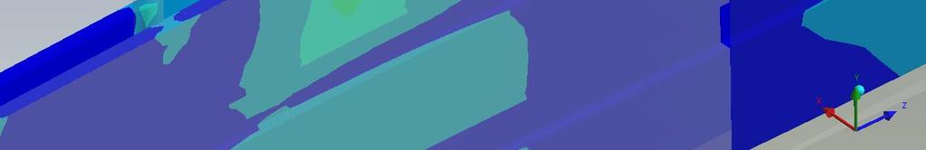
14 Results A series of plots showing the von Mises equivalent stress contours as well as displacement contours are presented in Figures 5 to 25. Animation files are also presented to show the deformation patterns and non- linear nature of the assembly behavior. The animation files are shown at an exaggerated scale (x10) to demonstrate more vividly the non-linear effects at the contact locations. 14
15 Time = 2.0 Figure 5. von Mises Equivalent Stress Contours, Complete Assembly. 15
16 Time = Figure 6. von Mises Equivalent Stress Contours, Complete Assembly. 16
17 Time = 1.0 Figure 7. von Mises Equivalent Stress Contours, Complete Assembly. 17


18 Time = 2.0 Figure 8. von Mises Equivalent Stress Contours, Cover Plate. 18
19 Time = Figure 9. von Mises Equivalent Stress Contours, Cover Plate. 19
20 Time = 1.0 Figure 10. von Mises Equivalent Stress Contours, Cover Plate. 20


21 Time = 2.0 Figure 11. von Mises Equivalent Stress Contours, Spline. 21
22 Time = Figure 12. von Mises Equivalent Stress Contours, Spline. 22
23 Time = 1.0 Figure 13. von Mises Equivalent Stress Contours, Spline. 23


24 Time = 2.0 Figure 14. von Mises Equivalent Stress Contours, Bolts. 24


25 Time = Figure 15. von Mises Equivalent Stress Contours, Bolts. 25


26 Time = 1.0 Figure 16. von Mises Equivalent Stress Contours, Bolts. 26
27 Time = 2.0 Figure 17. Deflection Contours, Assembly. 27
28 Time = Figure 18. Deflection Contours, Assembly. 28
29 Time = 1.0 Figure 19. Deflection Contours, Assembly. 29
30 Time = 2.0 Figure 20. Deflections, Global X Direction. 30
31 Time = Figure 21. Deflections, Global X Direction. 31
32 Time = 1.0 Figure 22. Deflections, Global X Direction. 32
33 Time = 2.0 Figure 23. Deflections, Global Y Direction. 33
34 Time = Figure 24. Deflections, Global Y Direction. 34
35 Time = 1.0 Figure 25. Deflections, Global Y Direction. 35
36 Table 1 is a summary of maximum computed stresses for the SJS configuration analyzed. The maximum stress computed occurs at the bonded contact regions that represent the base connection of the screw to the spline (see Figure 14). The value is 60, lbf/in. 2 This peek stress is highly concentrated and may not be a representative physical stress. The average stress at this location is closer to 30,000 lbf/in. 2 The maximum stress computed in the cover plate is 9,472 lbf/in. 2 (see Figure 8). The maximum stress computed in the spline is 18,922 lbf/in. 2 and is at a screw location (see Figure 11). The maximum upward deflection is in. and occurs when there is vertical load only y( (Time = 1.0, see Figure 25). The maximum downward deflection is in. and occurs when maximum torque is applied with the vertical load (Time = 2.0, see Figure 23). The maximum lateral deflection is in. at Time = 2.0 (see Figure 20). 36
37 Max. Stress 304 SS Plate (lbf/in. 2 ) Time = 1.0 Time = Time = 2.0 8,000 lbf 8,000 lbf plus 8,000 lbf plus only 12,800 lbf-in. torque 30,800 lbf-in. torque 6,669 6,643 9,472 Max. Stress 10,112 10,680 18,922 Spline (lbf/in. 2 ) Max. Stress Bolts (lbf/in. 2 ) Max. Upward Deflection (in.) 29,336 31,111 60, Max. Downward Deflection (in.) Max. Lateral Deflection (in.) Table 1. Summary of Maximum Stress and Deflections. 37
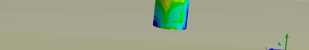
38 Animation Files Exaggerated Scale (x10) 38
39 Animation Files Exaggerated Scale (x10) 39
40 Animation Files Exaggerated Scale (x10) 40
41 Animation Files Exaggerated Scale (x10) 41
42 Comments The maximum stresses computed are at the fastening locations. These absolute peak stress magnitudes computed should not be viewed as quantitative. However, the peak stresses are likely to occur at the fastener locations therefore the fastening method should be reviewed to ensure safety after many application of loads. The stresses in the cover plate are acceptable and well below the yield and fatigue allowable for this material. The peak stress computed in the spline is at a fastener location and is also concentrated (see Figure 11). This should not be a concern accept for long term repeated loads and the possibility of a fastener loosening. As mentioned in the introduction an SJS configuration with keyways bonded to the cover plate was also analyzed. The intention for the keyways was to transfer the torque through the spline, foam and finally to the pavement. Since the keyways will have a clearance tolerance, the fasteners will initially iti react all the torque and the keyways will contact the spline after some deformation is allowed by the fasteners. 42
43 Comments (cont.) The efficiency of the keyways to transfer the torque on the cover plate for the SJS configuration with 9 fasteners and 10 keyways y was not demonstrated from the FE analysis results as most of the load went through the fasteners. Removal of the keyways and replacing with fasteners will give a more efficient structure to transfer the torque and some redundancy in the number of fasteners for long term safety. 43
Exercise 1. 3-Point Bending Using the Static Structural Module of. Ansys Workbench 14.0
 Exercise 1 3-Point Bending Using the Static Structural Module of Contents Ansys Workbench 14.0 Learn how to...1 Given...2 Questions...2 Taking advantage of symmetries...2 A. Getting started...3 A.1 Choose
2: Static analysis of a plate
 2: Static analysis of a plate Topics covered Project description Using SolidWorks Simulation interface Linear static analysis with solid elements Finding reaction forces Controlling discretization errors
Exercise 1. 3-Point Bending Using the GUI and the Bottom-up-Method
 Exercise 1 3-Point Bending Using the GUI and the Bottom-up-Method Contents Learn how to... 1 Given... 2 Questions... 2 Taking advantage of symmetries... 2 A. Preprocessor (Setting up the Model)... 3 A.1
Abaqus/CAE Axisymmetric Tutorial (Version 2016)
") Abaqus/CAE Axisymmetric Tutorial (Version 2016) Problem Description A round bar with tapered diameter has a total load of 1000 N applied to its top face. The bottom of the bar is completely fixed. Determine
Abaqus/CAE Axisymmetric Tutorial (Version 2016) Problem Description A round bar with tapered diameter has a total load of 1000 N applied to its top face. The bottom of the bar is completely fixed. Determine
Abaqus CAE Tutorial 6: Contact Problem
 ENGI 7706/7934: Finite Element Analysis Abaqus CAE Tutorial 6: Contact Problem Problem Description In this problem, a segment of an electrical contact switch (steel) is modeled by displacing the upper
Structural Analysis of an Aluminum Spiral Staircase. EMCH 407 Final Project Presented by: Marcos Lopez and Dillan Nguyen
 Structural Analysis of an Aluminum Spiral Staircase EMCH 407 Final Project Presented by: Marcos Lopez and Dillan Nguyen Abstract An old aluminum spiral staircase at Marcos home has been feeling really
Exercise 2: Mesh Resolution, Element Shapes, Basis Functions & Convergence Analyses
 Exercise 2: Mesh Resolution, Element Shapes, Basis Functions & Convergence Analyses Goals In this exercise, we will explore the strengths and weaknesses of different element types (tetrahedrons vs. hexahedrons,
CHAPTER 4. Numerical Models. descriptions of the boundary conditions, element types, validation, and the force
 CHAPTER 4 Numerical Models This chapter presents the development of numerical models for sandwich beams/plates subjected to four-point bending and the hydromat test system. Detailed descriptions of the
SDC. Engineering Analysis with COSMOSWorks. Paul M. Kurowski Ph.D., P.Eng. SolidWorks 2003 / COSMOSWorks 2003
 Engineering Analysis with COSMOSWorks SolidWorks 2003 / COSMOSWorks 2003 Paul M. Kurowski Ph.D., P.Eng. SDC PUBLICATIONS Design Generator, Inc. Schroff Development Corporation www.schroff.com www.schroff-europe.com
Structural re-design of engine components
 Structural re-design of engine components Product design cycle Design Development Testing Structural optimization Product knowledge Design freedom 2/18 Structural re-design of engine components Product
Sliding Split Tube Telescope
 LESSON 15 Sliding Split Tube Telescope Objectives: Shell-to-shell contact -accounting for shell thickness. Creating boundary conditions and loads by way of rigid surfaces. Simulate large displacements,
The part to be analyzed is the bracket from the tutorial of Chapter 3.
 Introduction to Solid Modeling Using SolidWorks 2007 COSMOSWorks Tutorial Page 1 In this tutorial, we will use the COSMOSWorks finite element analysis (FEA) program to analyze the response of a component
Crane Hook Design and Analysis
 Crane Hook Design and Analysis G Bhagyaraj 1, K Suryaprakash 2, K Subba Rao 3 1M.Tech. CAD/CAM, Godavari Institute of Engineering and Technology, Rajahmundry 2Associate Professor, Godavari Institute of
ES 128: Computer Assignment #4. Due in class on Monday, 12 April 2010
 ES 128: Computer Assignment #4 Due in class on Monday, 12 April 2010 Task 1. Study an elastic-plastic indentation problem. This problem combines plasticity with contact mechanics and has many rich aspects.
Revised Sheet Metal Simulation, J.E. Akin, Rice University
 Revised Sheet Metal Simulation, J.E. Akin, Rice University A SolidWorks simulation tutorial is just intended to illustrate where to find various icons that you would need in a real engineering analysis.
COMPUTER AIDED ENGINEERING. Part-1
 COMPUTER AIDED ENGINEERING Course no. 7962 Finite Element Modelling and Simulation Finite Element Modelling and Simulation Part-1 Modeling & Simulation System A system exists and operates in time and space.
CHAPTER 8 FINITE ELEMENT ANALYSIS
 If you have any questions about this tutorial, feel free to contact Wenjin Tao (w.tao@mst.edu). CHAPTER 8 FINITE ELEMENT ANALYSIS Finite Element Analysis (FEA) is a practical application of the Finite
Design of Arm & L-bracket and It s Optimization By Using Taguchi Method
 IOSR Journal of Mechanical and Civil Engineering (IOSR-JMCE) e-issn: 2278-1684,p-ISSN: 2320-334X PP. 28-38 www.iosrjournals.org Design of Arm & L-bracket and It s Optimization By Using Taguchi Method S.
Engineering Analysis with
 Engineering Analysis with SolidWorks Simulation 2013 Paul M. Kurowski SDC PUBLICATIONS Schroff Development Corporation Better Textbooks. Lower Prices. www.sdcpublications.com Visit the following websites
Aufgabe 1: Dreipunktbiegung mit ANSYS Workbench
 Aufgabe 1: Dreipunktbiegung mit ANSYS Workbench Contents Beam under 3-Pt Bending [Balken unter 3-Pkt-Biegung]... 2 Taking advantage of symmetries... 3 Starting and Configuring ANSYS Workbench... 4 A. Pre-Processing:
Modelling Flat Spring Performance Using FEA
 Modelling Flat Spring Performance Using FEA Blessing O Fatola, Patrick Keogh and Ben Hicks Department of Mechanical Engineering, University of Corresponding author bf223@bath.ac.uk Abstract. This paper
FEA and Topology Optimization of an Engine Mounting Bracket
 International Journal of Current Engineering and Technology E-ISSN 2277 4106, P-ISSN 2347 5161 2016 INPRESSCO, All Rights Reserved Available at http://inpressco.com/category/ijcet Research Article Sanket
Engineering Analysis with SolidWorks Simulation 2012
 Engineering Analysis with SolidWorks Simulation 2012 Paul M. Kurowski SDC PUBLICATIONS Schroff Development Corporation Better Textbooks. Lower Prices. www.sdcpublications.com Visit the following websites
Course in ANSYS. Example0153. ANSYS Computational Mechanics, AAU, Esbjerg
 Course in Example0153 Example Offshore structure F Objective: Display the deflection figure and von Mises stress distribution Tasks: Import geometry from IGES. Display the deflection figure? Display the
What makes Bolt Self-loosening Predictable?
 What makes Bolt Self-loosening Predictable? Abstract Dr.-Ing. R. Helfrich, Dr.-Ing. M. Klein (INTES GmbH, Germany) In mechanical engineering, bolts are frequently used as standard fastening elements, which
Spur Gears Static Stress Analysis with Linear Material Models
 Exercise A Spur Gears Static Stress Analysis with Linear Material Models Beam and Brick Elements Objective: Geometry: Determine the stress distribution in the spur gears when a moment of 93.75 in-lb is
SolidWorks. An Overview of SolidWorks and Its Associated Analysis Programs
 An Overview of SolidWorks and Its Associated Analysis Programs prepared by Prof. D. Xue University of Calgary SolidWorks - a solid modeling CAD tool. COSMOSWorks - a design analysis system fully integrated
ME Optimization of a Frame
 ME 475 - Optimization of a Frame Analysis Problem Statement: The following problem will be analyzed using Abaqus. 4 7 7 5,000 N 5,000 N 0,000 N 6 6 4 3 5 5 4 4 3 3 Figure. Full frame geometry and loading
DESIGN AND OPTIMIZATION OF ROTARY TURRET PLATE OF POUCHER MACHINE
 DESIGN AND OPTIMIZATION OF ROTARY TURRET PLATE OF POUCHER MACHINE Jigar G. Patel Institute of Technology, Nirma University, Ahmedabad 382481, India Email:14mmcc17@nirmuni.ac.in Mitesh B. Panchal Mechanical
ME 475 FEA of a Composite Panel
 ME 475 FEA of a Composite Panel Objectives: To determine the deflection and stress state of a composite panel subjected to asymmetric loading. Introduction: Composite laminates are composed of thin layers
Enhancing Productivity of a Roller Stand through Design Optimization using Manufacturing Simulation
 Enhancing Productivity of a Roller Stand through Design Optimization using Manufacturing Simulation B.R. Krishna Tej 1, N.Sasank Sai 1 and S.Deepak kumar* 1 Engineering Design and Research Center (EDRC)
Global to Local Model Interface for Deepwater Top Tension Risers
 Global to Local Model Interface for Deepwater Top Tension Risers Mateusz Podskarbi Karan Kakar 2H Offshore Inc, Houston, TX Abstract The water depths from which oil and gas are being produced are reaching
FEA Simulation Approach for Braking Linkage: A Comparison through Cross-section Modification
 International Journal of Mechanics and Solids. ISSN 0973-1881 Volume 12, Number 1 (2017), pp. 1-13 Research India Publications http://www.ripublication.com/ijms.htm FEA Simulation Approach for Braking
March 5-8, 2017 Hilton Phoenix / Mesa Hotel Mesa, Arizona Archive Session 7
 March 5-8, 2017 Hilton Phoenix / Mesa Hotel Mesa, Arizona Archive Session 7 2017 BiTS Workshop Image: tonda / istock Copyright Notice The presentation(s)/poster(s) in this publication comprise the Proceedings
CONTACT STATE AND STRESS ANALYSIS IN A KEY JOINT BY FEM
 PERJODICA POLYTECHNICA SER. ME CH. ENG. VOL. 36, NO. 1, PP. -15-60 (1992) CONTACT STATE AND STRESS ANALYSIS IN A KEY JOINT BY FEM K. VARADI and D. M. VERGHESE Institute of Machine Design Technical University,
Exercise 1: 3-Pt Bending using ANSYS Workbench
 Exercise 1: 3-Pt Bending using ANSYS Workbench Contents Starting and Configuring ANSYS Workbench... 2 1. Starting Windows on the MAC... 2 2. Login into Windows... 2 3. Start ANSYS Workbench... 2 4. Configuring
WORKSHOP 6.3 WELD FATIGUE USING NOMINAL STRESS METHOD. For ANSYS release 14
 WORKSHOP 6.3 WELD FATIGUE USING NOMINAL STRESS METHOD For ANSYS release 14 Objective: In this workshop, a weld fatigue analysis on a VKR-beam with a plate on top using the nominal stress method is demonstrated.
Using three-dimensional CURVIC contact models to predict stress concentration effects in an axisymmetric model
 Boundary Elements XXVII 245 Using three-dimensional CURVIC contact models to predict stress concentration effects in an axisymmetric model J. J. Rencis & S. R. Pisani Department of Mechanical Engineering,
Introduction to Engineering Analysis
 Chapter 1 Introduction to Engineering Analysis This chapter introduces you to the Stress Analysis and Dynamic Simulation environments. You learn how digital prototyping can be used to simulate your designs
Nerf Blaster Redesign
 Nerf Blaster Redesign ME4041 Computer Graphics and CAD April 0, 010 Submitted By: Michael Schulman Greg Mann Table of Contents Introduction. Objectives Modeling. 4 External Components 4 Internal Components.
ANALYSIS AND OPTIMIZATION OF FLYWHEEL
 Int. J. Mech. Eng. & Rob. Res. 2012 Sushama G Bawane et al., 2012 Research Paper ISSN 2278 0149 www.ijmerr.com Vol. 1, No. 2, July 2012 2012 IJMERR. All Rights Reserved ANALYSIS AND OPTIMIZATION OF FLYWHEEL
Finite Element Analysis of a 10 x 22 FRP Building for TRACOM Corporation
 Finite Element Analysis of a 10 x 22 FRP Building for TRACOM Corporation May 29, 2007 A. Background TRACOM Corporation designs and constructs Fiber Reinforced Plastic Buildings for use as shelters around
Modeling with CMU Mini-FEA Program
 Modeling with CMU Mini-FEA Program Introduction Finite element analsis (FEA) allows ou analze the stresses and displacements in a bod when forces are applied. FEA determines the stresses and displacements
Quarter Symmetry Tank Stress (Draft 4 Oct 24 06)
") Quarter Symmetry Tank Stress (Draft 4 Oct 24 06) Introduction You need to carry out the stress analysis of an outdoor water tank. Since it has quarter symmetry you start by building only one-fourth of
Quarter Symmetry Tank Stress (Draft 4 Oct 24 06) Introduction You need to carry out the stress analysis of an outdoor water tank. Since it has quarter symmetry you start by building only one-fourth of
Stiffness Analysis of the Tracker Support Bracket and Its Bolt Connections
 October 25, 2000 Stiffness Analysis of the Tracker Support Bracket and Its Bolt Connections Tommi Vanhala Helsinki Institute of Physics 1. INTRODUCTION...2 2. STIFFNESS ANALYSES...2 2.1 ENVELOPE...2 2.2
Topology Optimization Design of Automotive Engine Bracket
 Energy and Power Engineering, 2016, 8, 230-235 Published Online April 2016 in SciRes. http://www.scirp.org/journal/epe http://dx.doi.org/10.4236/epe.2016.84021 Topology Optimization Design of Automotive
Lesson 6: Assembly Structural Analysis
 Lesson 6: Assembly Structural Analysis In this lesson you will learn different approaches to analyze the assembly using assembly analysis connection properties between assembly components. In addition
Design and development of optimized sprocket for Track hoe
 Design and development of optimized sprocket for Track hoe Mr. Laxmikant P.Sutar 1, Prof. Prashant.G. Karajagi 2, Prof. Rahul Kulkarni 3 1 PG Student, Siddhant College of Engineering, Pune, India 2 Assistant
Visit the following websites to learn more about this book:
 Visit the following websites to learn more about this book: 6 Introduction to Finite Element Simulation Historically, finite element modeling tools were only capable of solving the simplest engineering
Stress Analysis of Bolted Joints Part II. Contact and Slip Analysis of a Four Bolt Joint
 Modern Mechanical Engineering, 2014, 4, 46-55 Published Online February 2014 (http://www.scirp.org/journal/mme) http://dx.doi.org/10.4236/mme.2014.41006 Stress Analysis of Bolted Joints Part II. Contact
Finite Element Analysis and Optimization of I.C. Engine Piston Using RADIOSS and OptiStruct
 Finite Element Analysis and Optimization of I.C. Engine Piston Using RADIOSS and OptiStruct Vivek Zolekar Student M. Tech. Mechanical (CAD/CAM) SGGSIE&T Nanded - 431 606 Dr. L.N. Wankhade Professor Department
ANSYS Workbench Guide
 ANSYS Workbench Guide Introduction This document serves as a step-by-step guide for conducting a Finite Element Analysis (FEA) using ANSYS Workbench. It will cover the use of the simulation package through
Efficient Shape Optimisation of an Aircraft Landing Gear Door Locking Mechanism by Coupling Abaqus to GENESIS
 Efficient Shape Optimisation of an Aircraft Landing Gear Door Locking Mechanism by Coupling Abaqus to GENESIS Mark Arnold and Martin Gambling Penso Consulting Ltd GRM Consulting Ltd Abstract: The objective
On an empirical investigation of the structural behaviour of robots
 On an empirical investigation of the structural behaviour of robots C. Doukas, J. Pandremenos, P. Stavropoulos, P. Fotinopoulos, G.Chryssolouris 1 1 Laboratory for Manufacturing Systems and Automation,
Offshore Platform Fluid Structure Interaction (FSI) Simulation
 Simulation") Offshore Platform Fluid Structure Interaction (FSI) Simulation Ali Marzaban, CD-adapco Murthy Lakshmiraju, CD-adapco Nigel Richardson, CD-adapco Mike Henneke, CD-adapco Guangyu Wu, Chevron Pedro M. Vargas,
Offshore Platform Fluid Structure Interaction (FSI) Simulation Ali Marzaban, CD-adapco Murthy Lakshmiraju, CD-adapco Nigel Richardson, CD-adapco Mike Henneke, CD-adapco Guangyu Wu, Chevron Pedro M. Vargas,
Computer Life (CPL) ISSN: Finite Element Analysis of Bearing Box on SolidWorks
 ISSN: Finite Element Analysis of Bearing Box on SolidWorks") Computer Life (CPL) ISSN: 1819-4818 Delivering Quality Science to the World Finite Element Analysis of Bearing Box on SolidWorks Chenling Zheng 1, a, Hang Li 1, b and Jianyong Li 1, c 1 Shandong University
Computer Life (CPL) ISSN: 1819-4818 Delivering Quality Science to the World Finite Element Analysis of Bearing Box on SolidWorks Chenling Zheng 1, a, Hang Li 1, b and Jianyong Li 1, c 1 Shandong University
THREE DIMENSIONAL DYNAMIC STRESS ANALYSES FOR A GEAR TEETH USING FINITE ELEMENT METHOD
 THREE DIMENSIONAL DYNAMIC STRESS ANALYSES FOR A GEAR TEETH USING FINITE ELEMENT METHOD Haval Kamal Asker Department of Mechanical Engineering, Faculty of Agriculture and Forestry, Duhok University, Duhok,
Analysis Steps 1. Start Abaqus and choose to create a new model database
 Source: Online tutorials for ABAQUS Problem Description The two dimensional bridge structure, which consists of steel T sections (b=0.25, h=0.25, I=0.125, t f =t w =0.05), is simply supported at its lower
Simulation of AJWSP10033_FOLDED _ST_FR
 Phone: 01922 453038 www.hyperon-simulation-and-cad-services.co.uk Simulation of AJWSP10033_FOLDED _ST_FR Date: 06 May 2017 Designer: Study name: AJWSP10033_FOLDED_STATIC Analysis type: Static Description
Learning Module 8 Shape Optimization
 Learning Module 8 Shape Optimization What is a Learning Module? Title Page Guide A Learning Module (LM) is a structured, concise, and self-sufficient learning resource. An LM provides the learner with
SIMULATION CAPABILITIES IN CREO
 SIMULATION CAPABILITIES IN CREO Enhance Your Product Design with Simulation & Using digital prototypes to understand how your designs perform in real-world conditions is vital to your product development
An Introductory SIGMA/W Example
 1 Introduction An Introductory SIGMA/W Example This is a fairly simple introductory example. The primary purpose is to demonstrate to new SIGMA/W users how to get started, to introduce the usual type of
Similar Pulley Wheel Description J.E. Akin, Rice University
 Similar Pulley Wheel Description J.E. Akin, Rice University The SolidWorks simulation tutorial on the analysis of an assembly suggested noting another type of boundary condition that is not illustrated
Non-Linear Analysis of Bolted Flush End-Plate Steel Beam-to-Column Connection Nur Ashikin Latip, Redzuan Abdulla
 Non-Linear Analysis of Bolted Flush End-Plate Steel Beam-to-Column Connection Nur Ashikin Latip, Redzuan Abdulla 1 Faculty of Civil Engineering, Universiti Teknologi Malaysia, Malaysia redzuan@utm.my Keywords:
ANSYS 5.6 Tutorials Lecture # 2 - Static Structural Analysis
 R50 ANSYS 5.6 Tutorials Lecture # 2 - Static Structural Analysis Example 1 Static Analysis of a Bracket 1. Problem Description: The objective of the problem is to demonstrate the basic ANSYS procedures
FINITE ELEMENT ANALYSIS (FEA) OF A C130 TOWING BAR
 OF A C130 TOWING BAR") FINITE ELEMENT ANALYSIS (FEA) OF A C130 TOWING BAR Fadzli Ibrahim* & Mohammad Shafiq Toha Mechanical & Aerospace Technology Division (BTJA), Science & Technology Research Institute for Defence (STRIDE),
FINITE ELEMENT ANALYSIS (FEA) OF A C130 TOWING BAR Fadzli Ibrahim* & Mohammad Shafiq Toha Mechanical & Aerospace Technology Division (BTJA), Science & Technology Research Institute for Defence (STRIDE),
CE Advanced Structural Analysis. Lab 4 SAP2000 Plane Elasticity
 Department of Civil & Geological Engineering COLLEGE OF ENGINEERING CE 463.3 Advanced Structural Analysis Lab 4 SAP2000 Plane Elasticity February 27 th, 2013 T.A: Ouafi Saha Professor: M. Boulfiza 1. Rectangular
Tutorial 1: Welded Frame - Problem Description
 Tutorial 1: Welded Frame - Problem Description Introduction In this first tutorial, we will analyse a simple frame: firstly as a welded frame, and secondly as a pin jointed truss. In each case, we will
Institute of Mechatronics and Information Systems
 EXERCISE 2 Free vibrations of a beam arget Getting familiar with the fundamental issues of free vibrations analysis of elastic medium, with the use of a finite element computation system ANSYS. Program
3DEXPERIENCE 2017x FINITE ELEMENT ESSENTIALS IN SDC USING SIMULIA/CATIA APPLICATIONS. Nader G. Zamani
 Nader G. Zamani FINITE ELEMENT ESSENTIALS IN 3DEXPERIENCE 2017x USING SIMULIA/CATIA APPLICATIONS SDC PUBLICATIONS Better Textbooks. Lower Prices. www.sdcpublications.com Powered by TCPDF (www.tcpdf.org)
Revision of the SolidWorks Variable Pressure Simulation Tutorial J.E. Akin, Rice University, Mechanical Engineering. Introduction
 Revision of the SolidWorks Variable Pressure Simulation Tutorial J.E. Akin, Rice University, Mechanical Engineering Introduction A SolidWorks simulation tutorial is just intended to illustrate where to
Engineering Effects of Boundary Conditions (Fixtures and Temperatures) J.E. Akin, Rice University, Mechanical Engineering
 J.E. Akin, Rice University, Mechanical Engineering") Engineering Effects of Boundary Conditions (Fixtures and Temperatures) J.E. Akin, Rice University, Mechanical Engineering Here SolidWorks stress simulation tutorials will be re-visited to show how they
Engineering Effects of Boundary Conditions (Fixtures and Temperatures) J.E. Akin, Rice University, Mechanical Engineering Here SolidWorks stress simulation tutorials will be re-visited to show how they
ANSYS AIM Tutorial Structural Analysis of a Plate with Hole
 ANSYS AIM Tutorial Structural Analysis of a Plate with Hole Author(s): Sebastian Vecchi, ANSYS Created using ANSYS AIM 18.1 Problem Specification Pre-Analysis & Start Up Analytical vs. Numerical Approaches
ME Optimization of a Truss
 ME 475 - Optimization of a Truss Analysis Problem Statement: The following problem will be analyzed using Abaqus and optimized using HEEDS. 4 5 8 2 11 3 10 6 9 1 7 12 6 m 300 kn 300 kn 22 m 35 m Figure
Abaqus/CAE (ver. 6.11) Nonlinear Buckling Tutorial
 Nonlinear Buckling Tutorial") Abaqus/CAE (ver. 6.11) Nonlinear Buckling Tutorial Problem Description This is the NAFEMS 1 proposed benchmark (Lee s frame buckling) problem. The applied load is based on the normalized (EI/L 2 ) value
Abaqus/CAE (ver. 6.11) Nonlinear Buckling Tutorial Problem Description This is the NAFEMS 1 proposed benchmark (Lee s frame buckling) problem. The applied load is based on the normalized (EI/L 2 ) value
Static Analysis of Bajaj Pulsar 150 CC Crankshaft Using ANSYS
 Static Analysis of Bajaj Pulsar 150 CC Crankshaft Using ANSYS Surekha S. Shelke 1, Dr. C. L. Dhamejani 2, A. S. Gadhave 3 1 P.G. Student, Department of Mechanical Engineering, JCOE Kuran 2 Principal, Department
3-D Numerical Simulation of Direct Aluminum Extrusion and Die Deformation
 3-D Numerical Simulation of Direct Aluminum Extrusion and Die Deformation ABSTRACT W.A.Assaad, University of Twente Enschede, The Netherlands H.J.M. Geijselaers, University of Twente Enschede, The Netherlands
Impact and Postbuckling Analyses
 ABAQUS/Explicit: Advanced Topics Lecture 8 Impact and Postbuckling Analyses ABAQUS/Explicit: Advanced Topics L8.2 Overview Geometric Imperfections for Postbuckling Analyses ABAQUS/Explicit: Advanced Topics
NEW WAVE OF CAD SYSTEMS AND ITS APPLICATION IN DESIGN
 Vol 4 No 3 NEW WAVE OF CAD SYSTEMS AND ITS APPLICATION IN DESIGN Ass Lecturer Mahmoud A Hassan Al-Qadisiyah University College of Engineering hasaaneng@yahoocom ABSTRACT This paper provides some lighting
Design Verification Procedure (DVP) Load Case Analysis of Car Bonnet
 Load Case Analysis of Car Bonnet") Design Verification Procedure (DVP) Load Case Analysis of Car Bonnet Mahesha J 1, Prashanth A S 2 M.Tech Student, Machine Design, Dr. A.I.T, Bangalore, India 1 Asst. Professor, Department of Mechanical
Design Verification Procedure (DVP) Load Case Analysis of Car Bonnet Mahesha J 1, Prashanth A S 2 M.Tech Student, Machine Design, Dr. A.I.T, Bangalore, India 1 Asst. Professor, Department of Mechanical
Krzysztof Dabrowiecki, Probe2000 Inc Southwest Test Conference, San Diego, CA June 08, 2004
 Structural stability of shelf probe cards Krzysztof Dabrowiecki, Probe2000 Inc Southwest Test Conference, San Diego, CA June 08, 2004 Presentation Outline Introduction Objectives Multi die applications
Plasticity Bending Machine Tutorial (FFlex)
") Plasticity Bending Machine Tutorial (FFlex) Copyright 2018 FunctionBay, Inc. All rights reserved. User and training documentation from FunctionBay, Inc. is subjected to the copyright laws of the Republic
Plasticity Bending Machine Tutorial (FFlex) Copyright 2018 FunctionBay, Inc. All rights reserved. User and training documentation from FunctionBay, Inc. is subjected to the copyright laws of the Republic
Optimizing the Utility Scale Solar Megahelion Drive End-Cap (Imperial Units)
") Autodesk Inventor Tutorial Exercise Optimizing the Utility Scale Solar Megahelion Drive End-Cap www.autodesk.com/sustainabilityworkshop Contents OPTIMIZING THE USS SOLAR TRACKING END CAP... 3 OBJECTIVE...
Autodesk Inventor Tutorial Exercise Optimizing the Utility Scale Solar Megahelion Drive End-Cap www.autodesk.com/sustainabilityworkshop Contents OPTIMIZING THE USS SOLAR TRACKING END CAP... 3 OBJECTIVE...
CHAPTER-10 DYNAMIC SIMULATION USING LS-DYNA
 DYNAMIC SIMULATION USING LS-DYNA CHAPTER-10 10.1 Introduction In the past few decades, the Finite Element Method (FEM) has been developed into a key indispensable technology in the modeling and simulation
Chapter 5 Modeling and Simulation of Mechanism
 Chapter 5 Modeling and Simulation of Mechanism In the present study, KED analysis of four bar planar mechanism using MATLAB program and ANSYS software has been carried out. The analysis has also been carried
CHAPTER 7 BEHAVIOUR OF THE COMBINED EFFECT OF ROOFING ELEMENTS
 CHAPTER 7 BEHAVIOUR OF THE COMBINED EFFECT OF ROOFING ELEMENTS 7.1 GENERAL An analytical study on behaviour of combined effect of optimised channel sections using ANSYS was carried out and discussed in
Stress Analysis of thick wall bellows using Finite Element Method
 Stress Analysis of thick wall bellows using Finite Element Method Digambar J. Pachpande Post Graduate Student Department of Mechanical Engineering V.J.T.I. Mumbai, India Prof. G. U. Tembhare Assistant
Pressure Vessel Engineering Ltd. ASME Calculations - CRN Assistance - Vessel Design - Finite Element Analysis
 PVEng Pressure Vessel Engineering Ltd. ASME Calculations - CRN Assistance - Vessel Design - Finite Element Analysis Design Conditions Code: ASME VIII-1 Year: 2007 Finite Element Analysis Report - VIII-1
Abaqus/CAE (ver. 6.10) Stringer Tutorial
 Stringer Tutorial") Abaqus/CAE (ver. 6.10) Stringer Tutorial Problem Description A table made of steel tubing with a solid steel top and shelf is loaded with an oblique impulse load. Determine the transient response of the
Abaqus/CAE (ver. 6.10) Stringer Tutorial Problem Description A table made of steel tubing with a solid steel top and shelf is loaded with an oblique impulse load. Determine the transient response of the
SimLab 14.3 Release Notes
 SimLab 14.3 Release Notes Highlights SimLab 14.0 introduced new graphical user interface and since then this has evolved continuously in subsequent versions. In addition, many new core features have been
Technical Report Example (1) Chartered (CEng) Membership
 Chartered (CEng) Membership") Technical Report Example (1) Chartered (CEng) Membership A TECHNICAL REPORT IN SUPPORT OF APPLICATION FOR CHARTERED MEMBERSHIP OF IGEM DESIGN OF 600 (103 BAR) 820MM SELF SEALING REPAIR CLAMP AND VERIFICATION
Technical Report Example (1) Chartered (CEng) Membership A TECHNICAL REPORT IN SUPPORT OF APPLICATION FOR CHARTERED MEMBERSHIP OF IGEM DESIGN OF 600 (103 BAR) 820MM SELF SEALING REPAIR CLAMP AND VERIFICATION
The Role of Finite Element Analysis in Light Aircraft Design and Certification
 The Role of Finite Element Analysis in Light Aircraft Design and Certification Nigel Bamber Wey Valley Aeronautics Ltd www.weyvalleyaero.co.uk Engineering Consultancy Civil and Military Aerospace and Motorsport
COMPARISON OF THE MECHANICAL PROPERTIES OF DIFFERENT MODELS OF AUTOMOTIVE ENGINE MOUNTING
 COMPARISON OF THE MECHANICAL PROPERTIES OF DIFFERENT MODELS OF AUTOMOTIVE ENGINE MOUNTING Haval Kamal Asker Mechanical Engineering, Faculty of Agriculture and Forestry, University of Duhok, Iraq E-Mail:
Using Photo Modeling to Obtain the Modes of a Structure
 Using Photo Modeling to Obtain the Modes of a Structure Shawn and Mark Richardson, Vibrant Technology, Inc., Scotts Valley, California Photo modeling technology has progressed to the point where a dimensionally
Finite Element Specialists and Engineering Consultants
 Finite Element Specialists and Engineering Consultants Limit Analysis Using Finite Element Techniques Seminar for the Advanced Structural Engineering Module College of Engineering, Mathematics & Physical
MAE 323: Lab 7. Instructions. Pressure Vessel Alex Grishin MAE 323 Lab Instructions 1
 Instructions MAE 323 Lab Instructions 1 Problem Definition Determine how different element types perform for modeling a cylindrical pressure vessel over a wide range of r/t ratios, and how the hoop stress
General modeling guidelines
 General modeling guidelines Some quotes from industry FEA experts: Finite element analysis is a very powerful tool with which to design products of superior quality. Like all tools, it can be used properly,
studying of the prying action effect in steel connection
 studying of the prying action effect in steel connection Saeed Faraji Graduate Student, Department of Civil Engineering, Islamic Azad University, Ahar Branch S-faraji@iau-ahar.ac.ir Paper Reference Number:
Stiffened Plate With Pressure Loading
 Supplementary Exercise - 3 Stiffened Plate With Pressure Loading Objective: geometry and 1/4 symmetry finite element model. beam elements using shell element edges. MSC.Patran 301 Exercise Workbook Supp3-1
Abstract. Introduction:
 Abstract This project analyzed a lifecycle test fixture for stress under generic test loading. The maximum stress is expected to occur near the shrink fit pin on the lever arm. The model was constructed