Robust Real-Time Eye Detection and Tracking Under Variable Lighting Conditions and Various Face Orientations
|
|
|
- May Harris
- 6 years ago
- Views:
Transcription
1 Robust Real-Time Eye Detection and Tracking Under Variable Lighting Conditions and Various Face Orientations Zhiwei Zhu a, Qiang Ji b a zhuz@rpi.edu Telephone: Department of Electrical, Computer, and Systems Engineering, Rensselaer Polytechnic Institute JEC 6219, Troy, NY b qji@ecse.rpi.edu Telephone: Department of Electrical, Computer, and Systems Engineering, Rensselaer Polytechnic Institute JEC 6044, Troy, NY Abstract Most eye trackers based on active IR illumination require distinctive bright pupil effect to work well. However, due to a variety of factors such as eye closure, eye occlusion, and external illumination interference, pupils are not bright enough for these methods to work well. This tends to significantly limit their scope of application. In this paper, we present an integrated eye tracker to overcome these limitations. By combining the latest technologies in appearance-based object recognition and tracking with active IR illumination, our eye tracker can robustly track eyes under variable and realistic lighting conditions and under various face orientations. In addition, our integrated eye tracker is able to handle occlusion, glasses, and to simultaneously track multiple people with different distances and poses to the camera. Results from an extensive experiment shows a significant improvement of our technique over existing eye tracking techniques. Key words: Eye Tracking, Support Vector Machine, Mean Shift, Kalman Filtering Preprint submitted to Elsevier Science 5 July 2004
2 1 Introduction As one of the salient features of the human face, human eyes play an important role in face detection, face recognition and facial expression analysis. Robust non-intrusive eye detection and tracking is a crucial step for vision based man-machine interaction technology to be widely accepted in common environments such as homes and offices. Eye tracking has also found applications in other areas including monitoring human vigilance [1], gaze-contingent smart graphics [2], and assisting people with disability. The existing work in eye detection and tracking can be classified into two categories: traditional image based passive approaches and the active IR based approaches. The former approaches detect eyes based on the unique intensity distribution or shape of the eyes. The underlying assumption is that the eyes appear different from the rest of the face both in shape and intensity. Eyes can be detected and tracked based on exploiting these differences. The active IR based approach, on the other hand, exploits the spectral (reflective) properties of pupils under near IR illumination to produce the bright/dark pupil effect. Eye detection and tracking is accomplished by detecting and tracking pupils. The traditional methods can be broadly classified into three categories: template based methods [3 9,8,10,11], appearance based methods [12 14] and feature based methods [15 23]. In the template based methods, a generic eye model, based on the eye shape, is designed first. Template matching is then used to search the image for the eyes. Nixon [10] proposed an approach for accurate measurement of eye spacing using Hough transform. The eye is modeled by a circle for the iris and a tailored ellipse for the sclera boundary. Their method, however, is time-consuming, needs a high contrast eye image, and only works with frontal faces. Deformable templates are commonly used [3 5]. First, an eye model, which is allowed to translate, rotate and deform to fit the best representation of the eye shape in the image, is designed. Then, the eye position can be obtained through a recursive process in an energy minimization sense. While this method can detect eyes accurately, it requires the eye model be properly initialized near the eyes. Furthermore, it is computationally expensive, and requires good image contrast for the method to converge correctly. The appearance based methods [12],[13], [14] detect eyes based on their photometric appearance. These methods usually need to collect a large amount of training data, representing the eyes of different subjects, under different face orientations, and under different illumination conditions. These data are used to train a classifier such as a neural network or the Support Vector Machine and detection is achieved via classification. In [12], Pentland et al. extended the eigenface technique to the description and coding of facial features, yielding eigeneyes, eigennoses and eigenmouths. For eye detection, they extracted an 2
3 appropriate eye templates for training and constructed a principal component projective space called Eigeneyes. Eye detection is accomplished by comparing a query image with an eye image in the eigeneyes space. Huang et al. [13] also employed the eigeneyes to perform initial eye positions detection. Huang et al. [14] presented a method to represent eye image using wavelets and to perform eye detection using RBF NN classifier. Reinders et al. [21] proposed several improvements on the neural network based eye detector. The trained neural network eye detector can detect rotated or scaled eyes under different lighting conditions. But it is trained for the frontal view face image only. Feature based methods explore the characteristics (such as edge and intensity of iris, the color distributions of the sclera and the flesh) of the eyes to identify some distinctive features around the eyes. Kawato et al [16] proposed a feature based method for eyes detection and tracking. Instead of detecting eyes, they propose to detect the point between two eyes. The authors believe the point is more stable and easier to detect than the eyes. Eyes are subsequently detected as two dark parts, symmetrically located on each side of the between-eyepoint. Feng et al. [8,9] designed a new eye model consisting of six landmarks (eye corner points). Their technique first locates the eye landmarks based on the variance projection function (VPF) and the located landmarks are then employed to guide the eye detection. Experiment shows their method will fail if the eye is closed or partially occluded by hair or face orientation. In addition, their technique may mistake eyebrows for eyes. Tian et al. [19] proposed a new method to track the eye and recover the eye parameters. The method requires to manually initialize the eye model in the first frame. The eye s inner corner and eyelids are tracked using a modified version of the Lucas-Kanade tracking algorithm [24]. The edge and intensity of iris are used to extract the shape information of the eye. Their method, however, requires a high contrast image to detect and track eye corners and to obtain a good edge image. In summary, the traditional image based eye tracking approaches detect and track the eyes by exploiting eyes differences in appearance and shape from the rest of the face. The special characteristics of the eye such as dark pupil, white sclera, circular iris, eye corners, eye shape, etc. are utilized to distinguish the human eye from other objects. But due to eye closure, eye occlusion, variability in scale and location, different lighting conditions, and face orientations, these differences will often diminish or even disappear. Wavelet filtering [25,26] has been commonly used in computer vision to reduce illumination effect by removing subbands sensitive to illumination change. But it only works under slight illumination variation. Illumination variation for eye tracking applications could be significant. Hence, the eye image will not look much different in appearance or shape from the rest of the face, and the traditional image based approaches can not work very well, especially for faces with non-frontal orientations, under different illuminations, and for different subjects. 3

.")

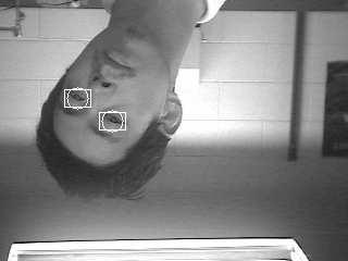
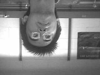
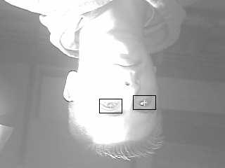
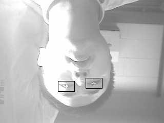
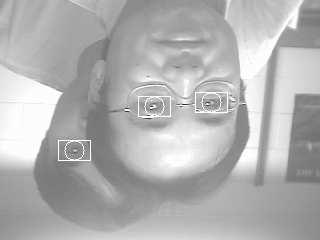
4 Eye detection and tracking based on the active remote IR illumination is a simple yet effective approach. It exploits the spectral (reflective) properties of the pupil under near IR illumination. Numerous techniques [27 31,1] have been developed based on this principle, including some commercial eye trackers [32,33]. They all rely on an active IR light source to produce the dark or bright pupil effects. Ebisawa et al. [27] generate the bright/dark pupil images based on a differential lighting scheme using two IR light sources (on and off camera axis). The eye can be tracked effectively by tracking the bright pupils in the difference image resulting from subtracting the dark pupil image from the bright pupil image. Later in [28], they further improved their method by using pupil brightness stabilization to eliminate the glass reflection. Morimoto et al. [29] also utilize the differential lighting scheme to generate the bright/dark pupil images, and pupil detection is done after thresholding the difference image. A larger temporal support is used to reduce artifacts caused mostly by head motion, and geometric constraints are used to group the pupils. Most of these methods require distinctive bright/dark pupil effect to work well. The success of such a system strongly depends on the brightness and size of the pupils, which are often affected by several factors including eye closure, eye occlusion due to face rotation, external illumination interferences, and the distances of the subjects to the camera. Figures 1 and 2 summarize different conditions under which the pupils may not appear very bright or even disappear. These conditions include eye closure (Figure 1 (a)) and oblique face orientations (Figure 1 (b) (c) and (d)), presence of other bright objects (due to either eye glasses glares or motion) as shown in Figure 2 (a) and (b), and external illumination interference as shown in Figure 2 (c). (a) (b) (c) (d) Fig. 1. The disappearance of the bright pupils due to eye closure (a) and oblique face orientations (b), (c), and (d). The absence of the bright pupils or even weak pupil intensity poses serious problems to the existing eye tracking methods using IR for they all require relatively stable lighting conditions, users close to the camera, small out-ofplane face rotations, and open and un-occluded eyes. These conditions impose 4
original image, (b)the corresponding thresholded difference image, which contains other bright regions around the real pupil blobs due to either eye glasses glares and rapid head motion, (c) Weak")


5 (a) (b) (c) Fig. 2. (a)original image, (b)the corresponding thresholded difference image, which contains other bright regions around the real pupil blobs due to either eye glasses glares and rapid head motion, (c) Weak pupils intensity due to strong external illumination interference. serious restrictions on the part of their systems as well as on the user, and therefore limit their application scope. Realistically, however, lighting can be variable in many application domains, the natural movement of head often involves out-of-plane rotation, eye closures due to blinking and winking are physiological necessities for humans. Furthermore, thick eye glasses tend to disturb the infrared light so much that the pupils appear very weak. It is therefore very important for the eye tracking system to be able to robustly and accurately track eyes under these conditions as well. To alleviate some of these problems, Ebisawa [28] proposed an image difference method based on two light sources to perform pupil detection under various lighting conditions. The background can be eliminated using the image difference method and the pupils can be easily detected by setting the threshold as low as possible in the difference image. They also proposed an ad hoc algorithm for eliminating the glares on the glasses, based on thresholding and morphological operations. However, the automatic determination of the threshold and the structure element size for morphological operations is difficult; and the threshold value cannot be set as low as possible considering the efficiency of the algorithm. Also, eliminating the noise blobs just according to their sizes is not enough. Haro[31] proposed to perform pupil tracking based on combining eye appearance, the bright pupil effect, and motion characteristics so that pupils can be separated from other equally bright objects in the scene. To do so, they proposed to verify the pupil blobs using conventional appearance based matching method and the motion characteristics of the eyes. But their method can not track the closed or occluded eyes or eyes with weak pupil intensity due to external illuminations interference. Ji et al. [1] proposed a real time subtraction and a special filter to eliminate the external light interferences. But their technique fails to track the closed/occluded eyes. To handle the presence of other bright objects, their method performs pupil verification based on the shape and size of pupil blobs to eliminate spurious pupils blobs. But usually, spurious blobs have similar shape and size to those of the pupil blobs as shown in Figure 2 and make it difficult to distinguish the real pupil blobs from the noise blobs based on only shape and size. 5
6 In this paper, we propose a real-time robust method for eye tracking under variable lighting conditions and face orientations, based on combining the appearance-based methods and the active IR illumination approach. Combining the respective strengths of different complementary techniques and overcoming their shortcomings, the proposed method uses an active infrared illumination to brighten subject s faces to produce the bright pupil effect. The bright pupil effect and the appearance of eyes are utilized simultaneously for eyes detection and tracking. The latest technologies in pattern classification recognition (the Support Vector Machine) and in object tracking (the meanshift) are employed for pupil detection and tracking based on eyes appearance. Some of the ideas presented in this paper have been briefly reported in [34],[35]. In this paper, we report our algorithm in details. Our method consists of two parts: eye detection and eye tracking. Eye detection is accomplished by simultaneously utilizing the bright/dark pupil effect under active IR illumination and the eye appearance pattern under ambient illumination via the Support Vector Machine. Eye tracking is composed of two major modules. The first module is a conventional Kalman filtering tracker based on the bright pupil. The Kalman filtering tracker is augmented with the Support Vector Machine classifier [36,37] to perform verification of the detected eyes. In case Kalman eye tracker fails due to either weak pupil intensity or the absence of the bright pupils, eye tracking based the on mean shift is activated [38] to continue tracking the eyes. Eye tracking returns to the Kalman filtering tracker as soon as the bright pupils reappear since eye tracking using bright pupils is much more robust than the mean shift tracker, which, we find, tends to drift away. The two trackers alternate, complementing each other and overcoming their limitations. Figure 3 summarizes our eye tracking algorithm. 2 Eye Detection To facilitate subsequent image processing, the person s face is illuminated using a near-infrared illuminator. The use of infrared illuminator serves three purposes: first it minimizes the impact of different ambient light conditions, therefore ensuring image quality under varying real-world conditions including poor illumination, day, and night; second, it allows to produce the bright/dark pupil effect, which constitutes the foundation for the proposed eye detection and tracking algorithm. Third, since near infrared is barely visible to the user, this will minimize any interference with the user s work. According to the original patent from Hutchinson [39], a bright pupil can be obtained if the eyes are illuminated with a near infrared illuminator beaming light along the camera optical axis at certain wavelength. At the near infrared wavelength, pupils reflect almost all infrared light they receive along the path back to the 6
7 Input IR Images Eye Detection Based on SVM Success? No Update the Target Model for the Mean Shift Eye Tracker Yes Kalman Filter Based Bright Pupil Eye Tracker Yes Success? No Mean Shift Eye Tracker No Yes Success? Fig. 3. The Combined Eye Tracking Flowchart camera, producing the bright pupil effect, very much similar to the red eye effect in photography. If illuminated off the camera optical axis, the pupils appear dark since the reflected light will not enter the camera lens. This produces the so called dark pupil effects. An example of the bright/dark pupils is given in Figure 4. Details about the construction of the IR illuminator and its configuration may be found in [40]. (a) (b) Fig. 4. The bright (a) and dark (b) pupils images. Given the IR illuminated eye images, eye detection is accomplished via pupil detection. Pupil detection is accomplished based on both the intensity of the pupils (the bright and dark pupils) and on the appearance of the eyes using the Support Vector Machine. Specifically, pupil detection starts with preprocessing to remove external illumination interference, followed by searching the whole image for pupils in terms of pupil intensity and eye appearance. Therefore, multiple pupils can be detected if there exist more than one person. The use 7


 from the bright eye image (even field), producing a difference image, with most of")
8 of Support Vector Machine (SVM) avoids falsely identifying a bright region as a pupil. Figure 5 gives an overview of the eye detection module. Even Field Image Interlaced Image Video Decoder Image Subtraction Adaptive Thresholding Odd Field Image Binary Image Eyes SVM Eye Verification Eye Candidates Geometric Constraints Blobs Connected Component Analysis Fig. 5. Eye Detection Block Diagram 2.1 Initial Eye Position Detection The detection algorithm starts with a preprocessing to minimize interference from illumination sources other than the IR illuminator. This includes sunlight and ambient light interference. A differential method is used to remove the background interference by subtracting the dark eye image (odd field) from the bright eye image (even field), producing a difference image, with most of the background and external illumination effects removed, as shown in Figure 6. For real time eye tracking, the image subtraction must be implemented efficiently in real time. To achieve this, we developed circuitry to synchronize the outer ring of LEDs and inner ring of LEDs with the even and odd fields of the interlaced image respectively so that they can be turned on and off alternately. When the even field is being scanned, the inner ring of LEDs is on and the outer ring of LEDs is off and vice versa when the even filed is scanned. The interlaced input image is subsequently de-interlaced via a video decoder, producing the even and odd field images as shown in Figure 6 (a) and (b). More on our image subtraction circuitry may be found in [40]. (a) (b) (c) Fig. 6. Background illumination interference removal (a) the even image field obtained with both ambient and IR light; (b) the odd image field obtained with only ambient light; (c) the image resulted from subtraction (b) from (a). The difference image is subsequently thresholded automatically based on its histogram, producing a binary image. Connected component analysis is then applied to the binary image to identify the binary blobs. Our task is then to 8

9 find out which of the blobs actually is the real pupil blob. Initially, we mark all the blobs as potential candidates for pupils as shown in Figure 7. Fig. 7. The thresholded difference image marked with pupil candidates 2.2 Eye Verification Using Support Vector Machine As shown in Figure 7, there are usually many potential candidates of pupils. Typically, pupils are found among the binary blobs. However, it is usually not possible to isolate the pupil blob only by picking the right threshold value, since pupils are often small and not bright enough compared with other noise blobs. Thus, we will have to make use of information other than intensity to correctly identify them. One initial way to distinguish the pupil blobs from other noise blobs is based on their geometric shapes. Usually, the pupil is an ellipse-like blob and we can use an ellipse fitting method [41] to extract the shape of each blob and use the shape and size to remove some blobs from further consideration. It must be noted, however, that due to scale change (distance to the camera) and to variability in individual pupil size, size is not a reliable criterion. It is only used to to remove very large or very small blobs. Shape criterion, on the other hand, is scale-invariant. Nevertheless, shape alone is not sufficient since there are often present other non-pupil blobs with similar shape and size as shown in Figure 8, where we can see that there are still several non pupil blobs left because they are so similar in shape and size that we can t distinguish the real pupil blobs from them. So we have to use other features. We observed that the eye region surrounding pupils has a unique intensity distribution. They appear different from other parts of the face in the dark pupil image as shown in Figure 4 (b). The appearance of an eye can therefore be utilized to separate it from non-eyes. We map the locations of the remaining binary blobs to the dark pupil images and then apply the Support Vector Machine (SVM) classifier [36,37] to automatically identify the binary blobs that correspond to eyes as discussed below. 9

10 Fig. 8. The thresholded difference image after removing some blobs based on their geometric properties (shape and size). The blobs marked with circles are selected for further consideration The Support Vector Machine SVM is a two-class classification method that finds the optimal decision hyperplane based on the concept of structural risk minimization. Ever since its introduction, SVM [36] has become increasingly popular. The theory of SVM can be briefly summarized as follows. For the case of two-class pattern recognition, the task of predictive learning from examples can be formulated as follows. Given a set of functions f α and an input domain R N of N dimensions: {f α : α Λ}, f α : R N { 1, +1}, (Λ is an index set) and a set of l examples: (x 1, y 1 ),...(x i, y i ),..., (x l, y l ), x i R N, y i { 1, +1}, where x i is an input feature vector and y i represents the class, which has only two values -1 and +1. Each (x i, y i ) is generated from an unknown probability distribution p(x, y), the goal is to find a particular function f α which provides the smallest possible value for the risk: R(α) = f α (x) y dp(x, y) (1) Suppose that there is a separating hyper-plane that separates the positive class from the negative class. The data characterizing the boundary between the two classes are called the support vectors since they alone define the optimal hyper-plane. First, a set (x i, y i ) of labeled training data are collected as the input to the SVM. Then, a trained SVM will be characterized by a set of N s support vectors s i, coefficient weights α i for the support vectors, class labels y i of the support vectors, and a constant term w 0. 10
11 For the linearly separable case, the linear decision surface (the hyperplane) is defined as w x + w 0 = 0, (2) where x is a point the hyperplane, denotes dot product, w is the normal of the hyperplane, and w 0 is the distance to the hyperplane from the origin. Through the use of training data, w can be estimated by N s w = α i y i s i, (3) i=1 Given w and w 0, an input vector x i can be classified into one of the two classes, depending on if w x + w 0 is larger or smaller than 0. Classes are often not linearly separable. In this case, SVM can be extended by using a kernel K(.,.), which performs a nonlinear mapping of the feature space to a higher dimension, where classes are linearly separable. The most common SVM kernels include Gaussian kernel, Radial-based kernel, and polynomial kernel. The decision rule with a kernel can be expressed as N s α i y i K(s i, x) + w 0 = 0 (4) i= SVM Training To use SVM, training data are needed to obtain the optimal hyper-plane. An eye image is represented as a vector I consisting of the original pixel values. For this project, after obtaining the positions of pupil candidates using the methods mentioned above, we obtain the sub-images from the dark image according to those positions as shown in Figure 9. Usually, the eyes are included in those cropped images of pixels. The cropped image data are processed using histogram equalization and normalized to a [0, 1] range before training. The eye training images were divided into two sets: positive set and negative set. In the positive image set, we include eye images of different gazes, different degrees of opening, different face poses, different subjects, and with/without glasses. The non-eye images were placed in the negative image set. Figures 10 and 11 contain examples of eye and non-eye images in the training sets, respectively. After finishing the above step, we get a training set, which has 558 positive images and 560 negative images. In order to obtain the best accuracy, we need to identify the best parameters for the SVM. In Table 2.2.2, we list three 11
 The thresholded difference image superimposed with possible pupil candidates (b) The dark image marked")


12 (a) (b) Fig. 9. (a) The thresholded difference image superimposed with possible pupil candidates (b) The dark image marked with possible eye candidates according to the positions of pupil candidates in (a). Fig. 10. The eye images in the positive training set. different SVM kernels with various parameter settings and each SVM was tested on 1757 eye candidate images obtained from different persons. From the above table, we can see that the best accuracy we can achieve is %, using a Gaussian kernel with a σ of Retraining Using Mis-labeled Data Usually, supervised learning machines rely only on the limited labeled training examples and can not reach very high learning accuracy. So we have to test on thousands of unlabeled data and pick up the mis-labeled data, then put them into the correct training sets and retrain the classifier again. After performing 12
13 Fig. 11. The non-eye images in the negative training set Table 1 Experiment results using 3 kernels with different parameters Kernel Type Deg Sigma # Support Accuracy σ Vectors Linear Polynomial Polynomial Polynomial Gaussian Gaussian Gaussian Gaussian Gaussian this procedure on the unlabeled data obtained from different conditions several times, we can boost the accuracy of the learning machine at the cost of extra time needed for re-training. Specifically, we have eye data set from ten people, which are obtained using the same method. We choose the first person s data set and label the eye images and non-eye images manually, then we train the Gaussian SVM on this training set and test Gaussian SVM on the second person s data set. We check the second person s data one by one, pick up all the mis-labeled data, label them correctly and add them into the training set. After finishing the above step, we retrain the SVM on this increased training set and repeat the above step on the next person s data set. The whole process then repeats until the classification errors stabilize. Through the retraining process, we can significantly boost the accuracy of the Gaussian SVM. 13
14 2.2.4 Eye Detection with SVM During eye detection, we crop the regions in the dark pupil image according to the locations of pupil candidates in the difference image as shown in Figure 9 (b). After some preprocessing on these eye candidate images, they will be provided to the trained SVM for classification. The trained SVM will classify the input vector I into eye class or non-eye class. Figure 12 shows that the SVM eye classifier correctly identifies the real eye regions as marked. (a) (b) Fig. 12. (a) (b) The images marked with identified eyes. Compared with images in Figure 9 (b), many false alarms have been removed. Pupil verification with SVM works reasonably well and can generalize to people of the same race. However, for people from a race that is significantly different from those in training images, the SVM may fail and need to be retrained. SVM can work under different illumination conditions due to the intensity normalization for the training images via histogram equalization. 3 Eye Tracking Algorithm Given the detected eyes in the initial frames, the eyes in subsequent frames can be tracked from frame to frame. Eye tracking can be done by performing pupil detection in each frame. This brute force method, however, will significantly slow down the speed of pupil tracking, making real time pupil tracking impossible since it needs to search the entire image for each frame. This can be done more efficiently by using the scheme of prediction and detection. Kalman filtering [42] provides a mechanism to accomplish this. The Kalman pupil tracker, however, may fail if pupils are not bright enough under the conditions mentioned previously. In addition, rapid head movement may also cause the tracker to lose the eyes. This problem is addressed by augmenting the Kalman tracker with the mean shift tracker. Figure 13 summarizes our eye tracking scheme. Specifically, after locating the eyes in the initial frames, 14
15 Kalman filtering is activated to track bright pupils. If it fails in a frame due to disappearance of bright pupils, eye tracking based on the mean shift will take over. Our eye tracker will return to bright pupil tracking as soon as bright pupil appears again since it is much more robust and reliable tracking. Pupil detection will be activated if the mean shift tracking fails. These two stage eye trackers work together and they complement each other. The robustness of the eye tracker is improved significantly. The Kalman tracking, the mean shift tracking, and their integration are briefly discussed below. Eye detection No Success? Yes Update the eye target model for Mean shift eye tracker Kalman filter based bright pupil eye tracker Yes Success? Yes No Mean Shift Tracker Initialize estimated center (y0) with Kalman filter, then y1=y0 Calculate the combined weights (bright pupil image and dark pupil image as two channels) No y1=y0 Calculate the new target center y0 No dis(y1-y0)<threshold value? Yes Bhattacharyya coefficient < threshold value? Fig. 13. The Combined Eye Tracking Flowchart 15
16 3.1 Eye (pupil) Tracking with Kalman Filtering A Kalman filter is a set of recursive algorithms that estimate the position and uncertainty of moving targets in the next time frame, that is, where to look for the targets, and how large a region should be searched in the next frame around the predicted position in order to find the targets with certain confidence. It recursively conditions current estimate on all of the past measurements and the process is repeated with the previous posterior estimates used to project the new a priori estimates. This recursive nature is one of the very appealing features of the Kalman filter since it makes practical implementation much more feasible. Our pupil tracking method based on Kalman filtering can be formalized as follows. The state of a pupil at each time instance (frame) t can be characterized by its position and velocity. Let (c t, r t ) represent the pupil pixel position (its centroid) at time t and (u t, v t ) be its velocity at time t in c and r directions respectively. The state vector at time t can therefore be represented as X t = (c t r t u t v t ) t. According to the theory of Kalman filtering [43], X t+1, the state vector at the next time frame t+1, linearly relates to current state X t by the system model as follows X t+1 = ΦX t + W t (5) where Φ is the state transition matrix and W t represents system perturbation. W t is normally distributed as p(w t ) N(0, Q), and Q represents the process noise covariance. We further assume that a fast feature extractor estimates Z t = (ĉ t, ˆr t ), the detected pupil position at time t. Therefore, the measurement model in the form needed by the Kalman filter is Z t = HX t + M t (6) where matrix H relates current state to current measurement and M t represents measurement uncertainty. M t is normally distributed as p(m t ) N(0, R), and R is the measurement noise covariance. For simplicity and since Z t only involves position, H can be represented as H =
17 The feature detector (e.g., thresholding or correlation) searches the region as determined by the projected pupil position and its uncertainty to find the feature point at time t + 1. The detected point is then combined with the prediction estimation to produce the final estimate. Specifically, given the state model in equation 5 and measurement model in equation 6 as well as some initial conditions, the state vector X t+1, along with its covariance matrix Σ t+1, can be updated as follows. For subsequent discussion, let us define a few more variables. Let X t+1 be the estimated state at time t+1, resulting from using the system model only. It is often referred to as the prior state estimate. X t+1 differs from X t+1 in that it is estimated using both the system model (equation 5) and the measurement model (equation 6). X t+1 is usually referred as the posterior state estimate. Let Σ t+1 and Σ t+1 be the covariance matrices for the state estimates X t+1 and X t+1 respectively. They characterize the uncertainties associated with the prior and posterior state estimates. The goal of Kalman filtering is therefore to estimate X t+1 and Σ t+1 given X t, Σ t, Z t, and the system and measurement models. The Kalman filtering algorithm for state prediction and updating may be summarized below. (1) State prediction Given current state X t and its covariance matrix Σ t, state prediction involves two steps: state projection (X t+1) and error covariance estimation (Σ t+1) as summarized in Eq. 7 and Eq. 8. X t+1 = ΦX t (7) Σ t+1 = ΦΣ t Φ t + Q t (8) Given the prior estimate X t+1, its covariance matrix Σ t+1, pupil detection is performed to detect the pupil around X t+1, with the search area determined by Σ t+1. In practice, to speed up the computation, the values of Σ t+1[0][0] and Σ t+1[1][1] are used to compute the search area size. Specifically, the search area size is chosen as 20+2*Σ t+1[0][0] pixels and 20+2*Σ t+1[1][1] pixels, where 20 by 20 pixels is the basic window size. This means the larger the Σ t+1[0][0] and Σ t+1[1][1] are, the more uncertainty of the estimation is, and the larger the search area is. The search area is therefore adaptively adjusted. Therefore, the pupil can be located quickly. (2) State updating The detected pupil position is represented by Z t+1. Then, state updating can be performed to derive the final state and its covariance matrix. The first task during state updating is to compute the Kalman gain K t+1. It is done as follows 17
18 K t+1 = Σ t+1h T HΣ t+1h T + R (9) The gain matrix K can be physically interpreted as a weighting factor to determine the contribution of measurement Z t+1 and prediction HX t+1 to the posterior state estimate X t+1. The next step is to to generate a posteriori state estimate X t+1 by incorporating the measurement into equation 5. X t+1 is computed as follows X t+1 = X t+1 + K t+1 (Z t+1 HX t+1) (10) The final step is to obtain the posteriori error covariance estimate. It is computed as follows Σ t+1 = (I K t+1 H)Σ t+1 (11) After each time and measurement update pair, the Kalman filter recursively conditions current estimate on all of the past measurements and the process is repeated with the previous posterior estimates used to project a new a priori estimate. The Kalman filter pupil tracker works reasonably well under frontal face rotation with the eye open. However, it will fail if the pupils are not bright due to either face orientation or external illumination interferences. The Kalman filter also fails when a sudden head movement occurs due to incorrect prediction because the assumption of smooth head motion has been violated. In each case, Kalman filtering fails because the Kalman filter detector can not detect pupils. We propose to use the mean shift tracking to augment Kalman filtering tracking to overcome this limitation. 3.2 Mean Shift Eye Tracking Due to the IR illumination, the eye region in the dark and bright pupil images exhibits strong and unique visual patterns such as the dark iris in the white part. This unique pattern should be utilized to track eyes in case the bright pupils fail to appear on the difference images. This is accomplished via the use of the mean shift tracking. Mean shift tracking is an appearance based object tracking method. It employs mean shift analysis to identify a target candidate region, which has the most similar appearance to the target model in terms of intensity distribution. 18
19 3.2.1 Similarity Measure The similarity of two distributions can be expressed by a metric based on the Bhattacharyya coefficient as described in [38]. The derivation of the Bhattacharyya coefficient from sample data involves the estimation of the target density q and the candidate density p, for which we employ the histogram formulation. Therefore, the discrete density ˆq = {ˆq u } u=1...m (with mu=1 ˆq u = 1 ) is estimated from the m-bin histogram of the target model, while ˆp(y) = {ˆp u (y)} u=1...m (with m u=1 ˆp u = 1 ) is estimated at a given location y from the m-bin histogram of the target candidate. Then at location y, the sample estimate of the Bhattacharyya coefficient for target density q and candidate density p(y) is given by ρ(y) ρ [ˆp(y), ˆq] = m u=1 ˆp uˆq u (12) The distance between two distributions can be defined as d(y) = 1 ρ [ˆp(y), ˆq] (13) Eye Appearance Model To reliably characterize the intensity distribution of eyes and non-eyes, the intensity distribution is characterized by two images: even and odd field images, resulting from de-interlacing the original input images. They are under different illuminations, with one producing bright pupils and the other producing dark pupils as shown in Figure 14. The use of two channel images to characterize eye appearance represents a new contribution and can therefore improve the accuracy of eye detection. (a) (b) (c) (d) Fig. 14. The eye images: (a)(b) left and right bright pupil eyes; (c)(d) corresponding left and right dark pupil eyes Thus, there are two different feature probability distributions of the eye target corresponding to dark pupil and bright pupil images respectively. We use a 2D joint histogram, which is derived from the grey level dark pupil and bright pupil image spaces with m = l l bins, to represent the feature probability distribution of the eyes. Before calculating the histogram, we employ a convex and monotonic decreasing kernel profile k to assign a smaller weight to the locations that are farther from the center of the target. Let us denote by {x i } i=1...nh the pixel locations of a target candidate that has n h pixels, centered 19
20 at y in the current frame. The probability distribution of the intensity vector I = (I b, I d ), where I d and I b represent the intensities in the dark and bright images respectively, in the target candidate is given by ˆp u (y) = nh i=1 k( y x i h 2 )δ[b(x i ) u] nh i=1 k( y x i h 2 ) where u=1,2,..,m (14) in which the b(x i ) is the index to a bin in the joint histogram of the intensity vector I at location x i, h is the radius of the kernel profile and δ is the Kronecker delta function. The eye model distribution q can be built in a similar fashion Algorithm After locating the eyes in the previous frame, we construct an eye model ˆq using Equation 14 based on the detected eyes in the previous frame. We then predict the locations y 0 of eyes at current frame using the Kalman filter. Then we treat y 0 as the initial position and use the mean shift iterations to find the most similar eye candidate to the eye target model in the current frame using the following algorithm. (1) Initialize the location of the target in the current frame with y 0, then compute the distribution {ˆp u (y 0 )} u=1...m using Equation 14 and evaluate similarity measure (Bhattacharyya coefficient) between the model density ˆq and target candidate density ˆp ρ[ˆp(y 0 ), ˆq] = m u=1 ˆp u (y 0 )ˆq u (15) (2) Derive the weights {w i } i=1...nh according to m ˆqu w i = δ[b(x i ) u] u=1 ˆp u (y 0 ) (16) (3) Based on the mean shift vector, derive the new location of the eye target y 1 = nh i=1 x i w i g( y 0 x i 2 ) h nh i=1 w i g( y 0 x i 2 ) h (17) where g(x) = k (x) and then update {ˆp u (y 1 )} u=1...m, and evaluate ρ[ˆp(y 1 ), ˆq] = m u=1 ˆp u (y 1 )ˆq u (18) 20
![(4) While ρ[ˆp(y 1 ), ˆq] < ρ[ˆp(y 0 ), ˆq] Do y 1 0.5(y 0 + y 1 ) This is necessary to avoid the mean shift tracker moving to an incorrect location.](/docs-images/71/65960599/images/21-1.jpg "(5) If y 1 y 0 < ε, stop, where ε is the termination threshold Otherwise, set y 0 y 1 and go to step 1.")
21 (4) While ρ[ˆp(y 1 ), ˆq] < ρ[ˆp(y 0 ), ˆq] Do y 1 0.5(y 0 + y 1 ) This is necessary to avoid the mean shift tracker moving to an incorrect location. (5) If y 1 y 0 < ε, stop, where ε is the termination threshold Otherwise, set y 0 y 1 and go to step 1. The new eye locations in the current frame can be achieved in a few iterations compared to the correlation based approaches, which must perform an exhaustive search around the previous eye location. Due to the simplicity of the calculations, it s much faster than correlation. Figure 15(b) plots the surface for the Bhattacharyya coefficient of the large rectangle marked in Figure 15(a). The mean shift algorithm exploits the gradient of the surface to climb, from its initial position, to the closest peak that represents the maximum value of the similarity measure. (a) (b) Fig. 15. (a) The image frame 13; (b) Values of Bhattacharyya coefficient corresponding to the marked region(40 40 pixels) around the left eye in frame 13. Mean shift algorithm converges from the initial location( ) to the convergence point( ), which is a mode of the Bhattacharyya surface Mean Shift Tracking Parameters The mean shift algorithm is sensitive to the window size and the histogram quantization value. In order to obtain the best performance of the mean shift tracker for a specific task, we have to find the appropriate histogram quantization value and the proper window size. We choose several image sequences and manually locate the left eye positions in these frames. Then we run the 21
22 mean shift eye tracker under different window sizes and different histogram quantization values, we evaluate the performance of mean shift eye tracker under those conditions using the following criterion: α error = N i=1 (y i (tracked) y i(manual)) 2 /N (19) where N is the number of image frames and y i (tracked) is the left eye location tracked by mean shift tracker in the image frame i; y i(manual) is the left eye location manually located by the person in the image frame i. We treat the manually selected eye locations as the correct left eye locations. (a) (b) Fig. 16. The error distribution of tracking results: (a) error distribution vs. intensity quantization values and different window sizes; (b) error distribution vs. quantization levels only. The intensity histogram is scaled in the range of 0 to 255/(2 q ), q is the quantization value. The results are plotted in Fig. 16. From figure 16 (a) and (b), we can determine the optimal quantization level to be 2 5 while the optimal window size is 20*20 pixels. Figure 17 shows some tracking results with these parameters. The mean-shift tracker, however, is sensitive to its initial placement. It may not converge or converge to a local minimum if placed initially far from the optimal location. It usually converges to the mode, closest to its initial position. If the initial location is in the valley between two modes, the mean shift may not converge to any (local maxima) peaks as shown in Figure 18. This demonstrates the sensitivity of mean-shift tracker to initial placement of the detector. 22


23 (frame 1) (frame 13) (frame 27) (frame 46) (frame 63) (frame 88) (frame 100) (frame 130) Fig. 17. Mean shift tracking both eyes with initial search area of 40*40 pixels, as represented by the large black rectangle. The eyes marked with white rectangles in frame 1 are used as the eye model and the tracked eyes in the following frames are marked by the smaller black rectangles Experiments On the Mean Shift Eye Tracking In order to study the performance of the mean-shift tracker, we apply it to sequences that contain images with weak or partially occluded or no bright pupils. We noticed when bright pupils disappear due to either eye closure or face rotations as shown in Figure 19, the Kalman filter fails because there are no bright pupil blobs in the difference images. However the mean shift tracker compensates for the failure of bright pupil tracker because it is an appearance based tracker that tracks the eyes according to the intensity statistical distributions of the eye regions and does not need bright pupils. The black rectangles in Figure 19 represent the eye locations tracked by the mean shift 23
 Image of frame 135, with the initial eye position marked and initial search area")
 Values of Bhattacharyya coefficient corresponding to the marked region(40 40 pixels)")
(which is in the valley")
 (b) (c) (d) Fig. 19.")
24 (a) (b) Fig. 18. (a) Image of frame 135, with the initial eye position marked and initial search area outlined by the large black rectangle. (b) Values of Bhattacharyya coefficient corresponding to the marked region(40 40 pixels) around the left eye in (a). Mean shift algorithm can not converge from the initial location( )(which is in the valley of two modes) to the correct mode of the surface. Instead, it is trapped in the valley. tracker. (a) (b) (c) (d) Fig. 19. Bright pupil based Kalman tracker fails to track eyes due to absence of bright pupils caused by either eye closure or oblique face orientations. The mean shift eye tracker, however, tracks eyes successfully as indicated by the black rectangles. 24
25 4 Combining Kalman Filtering Tracking with Mean Shift Tracking The mean shift tracking is fast and handles noise well. But it is easily distracted by nearby similar targets such as the nearby region that appears similar to the eyes. This is partially because of the histogram representation of the eyes appearance, which does not contain any information about the relative spatial relationships among pixels. The distraction manifests primarily as errors in the calculated center of the eyes. The mean shift tracker does not have the capability of self-correction and the errors therefore tend to accumulate and propagate to subsequent frames as tracking progresses and eventually the tracker drifts away. Another factor that could lead to errors with eye tracking based on mean shift is that the mean shift tracker can not continuously update its eye model despite the fact that the eyes look significantly different under different face orientations and lighting conditions as demonstrated in the left column of Figure 20. We can see that the mean shift eye tracker can not identify the correct eye location when the eyes appear significantly different from the model eyes images due to face orientation change. To overcome these limitations with mean shift tracker, we propose to combine the Kalman filter tracking with the mean shift tracking to overcome their respective limitations and to take advantage their strengths. The two trackers are activated alternately. The Kalman tracker is first initiated, assuming the presence of the bright pupils. When the bright pupils appear weak or disappear, the mean shift tracker is activated to take over the tracking. Mean shift tracking continues until the reappearance of the bright pupils, when the Kalman tracker takes over. To avoid the mean shift tracker drift away, the target eye model is continuously updated by the eyes successfully detected by the Kalman tracker. The right column of Figure 20 shows the results of tracking the same sequence with the integrated eye tracker as the one shown on left column. It is apparent that the integrated tracker can correct the drift problem of the mean shift tracker. 5 Experimental Results In this section, we will present results from an extensive experiment we conducted to validate the performance of our integrated eye tracker under different conditions. 25
26 5.1 Eye tracking Under Significant Head Pose Changes Here, we show some qualitative and quantitative results to demonstrate the performance our tracker under different face orientations. Figure 21 visually shows the typical tracking results for a person undergoing significant face pose changes, where the black rectangles represent the mean-shift tracker while the white rectangles represent the Kalman filter tracker. Additional results for different subjects under significant head rotations are shown in Figure 22. We can see that under significant head pose changes, the eyes will be either partially occluded or the appearance of eyes will be significantly different from the eyes with frontal faces. But the two eye trackers alternate reliably, detecting the eyes under different head orientations, with eyes either open, closed or partially occluded. To further confirm this quantitatively, we manually located the positions of the eyes for two typical sequences and they serve as the ground-truth eye positions. The tracked eye positions are then compared with the ground-truth data. The results are summarized in Tables 2 and 3. From the tracking statistics in Tables 2 and 3, we can conclude that the integrated eye tracker is much more accurate than the Kalman filter pupil tracker, especially for the closed eyes and partially occluded eyes due to face rotations. These results demonstrate that this combination of two tracking techniques produces much better tracking results than using either of them individually. 5.2 Eye Tracking Under Different Illuminations In this experiment, we demonstrate the performance of our integrated tracker under different illumination conditions. We vary the light conditions during the tracking. The experiment included first turning off the ambient lights, followed by using a mobile light source and positioning it close to the people to produce strong external light interference. The external mobile light produces significant shadows as well as intensity saturation on the subject s faces. Figure 23 visually shows the sample tracking results for two individuals. Despite these somewhat extreme conditions, our eye tracker managed to track the eyes correctly. Because of the use of IR, the faces are still visible and eyes are tracked even under darkness. It is apparent that illumination change does not adversely affect the performance of our technique as much. This may be attributed to the simultaneous use of active IR sensing, image intensity normalization for eye detection using SVM, and the dynamic eye model updating for the mean shift tracker. 26
27 Table 2 Tracking statistics comparison for both trackers under different eyes conditions (open, closed, occluded) on the first person Image Bright pupil Combined 600 frames tracker tracker Left eye (open) 452 frames 400/ /452 Left eye (closed) 66 frames 0/66 66/66 Left eye (occluded) 82 frames 0/82 82/82 Right eye (open) 425 frames 389/ /425 Right eye (closed) 66 frames 0/66 66/66 Right eye (occluded) 109 frames 0/ / Eye tracking with glasses The significant eye appearance changes with glasses. Furthermore, the glares on the glasses caused by light reflections present significant challenges to eye tracking with glasses. In Figure 24, we show the results of applying our eye tracker to persons wearing glasses. We can see that our eye tracker can still detect and track eyes robustly and accurately for people with glasses. However, our study shows that when the head orientation is such that the glares completely occludes the pupils, our tracker will fail. This is a problem that we will tackle in the future. 5.4 Eye tracking with multiple people Our eye tracker not only can track the eyes of one person but also can track multiple people s eyes simultaneously. Here, we show the results of applying our eye tracker to simultaneously track multiple people s eyes with different distances and face poses to the camera. The result is presented in Figure 25. This experiment demonstrates the versatility of our eye tracker. 27
28 Table 3 Tracking statistics comparison for both trackers under different eyes conditions (open, closed, occluded) on the second person Image Sequence 1 Bright pupil Combined 600 frames tracker tracker Left eye (open) 421 frames 300/ /421 Left eye (closed) 78 frames 0/78 60/78 Left eye (occluded) 101 frames 0/101 60/101 Right eye (open) 463 frames 336/ /463 Right eye (closed) 78 frames 0/78 78/78 Right eye (occluded) 59 frames 0/59 59/ Occlusion Handling Eyes are often partially or completely occluded either by face due to oblique face orientations or by hands or by other objects. A good eye tracker should be able to track eyes under partial occlusion and be able to detect complete occlusion and re-detect the eyes after the complete occlusion is removed. In Figure 26, two persons are moving in front of the camera, and one person s eyes are occluded by another s head when they are crossing. As shown in Figure 26, when the rear person moves from right to left, the head of the front person starts to occlude his eyes, beginning with one and then two eyes getting completely occluded. As shown, our tracker can still correctly track an eye even though it is partially occluded. When both eyes are completely occluded, our tracker detects this situation. As soon as the eyes reappear in the image, our eye tracker will capture the eyes one by one immediately as shown in Figure 26. This experiment shows the robustness of our method to occlusions. 28
29 6 Summary In this paper, we present an integrated eye tracker to track eyes robustly under various illuminations and face orientations. Our method performs well regardless of whether the pupils are directly visible or not. This has been achieved by combining an appearance based pattern recognition method (SVM) and object tracking (Mean Shift) with a bright-pupil eye tracker based on Kalman filtering. Specifically, we take the following measures. First, the use of SVM for pupil detection complements with eyes detection based on bright pupils from IR illumination, allowing to detect eyes in the presence of other bright objects; second, two channels (dark-pupil and bright-pupil eye images) are used to characterize the statistical distributions of the eye, based on which a Mean Shift eye tracker is developed. Third, the eye model is continuously updated by the eye successfully detected from the last Kalman tracker to avoid error propagation with the mean shift tracker. Finally, the experimental determination of the optimal window size and quantization level for mean shift tracking further enhances the performance of our technique. Experiments show these enhancements have led to a significant improvement in eye tracking robustness and accuracy over existing eye trackers, especially under various conditions identified in section 1. Furthermore, our integrated eye tracker is demonstrated to be able to handle occlusion, people with glasses, and to simultaneously track multiple people of different poses and scales. The lessons we learn from this research are: 1) perform active vision (e.g. active IR illumination) to produce quality input images and to simplify the subsequent image processing; 2) combine different complementary techniques to utilize their respective strengths and to overcome their limitations, leading to a much more robust technique than using each technique individually. 7 Acknowledgments This work is partially supported by a grant from AFOSR and a grant from Honda R&D Americas Inc., Mountain View, CA. References [1] Q. Ji, X. Yang, Real time visual cues extraction for monitoring driver vigilance, in: Proc. of International Workshop on Computer Vision Systems, Vancouver, Canada,
30 [2] Q. Ji, Z. Zhu, Eye and gaze tracking for interactive graphic display, in: 2nd International Symposium on Smart Graphics, Hawthorne, NY, USA, [3] A. Yuille, P. Hallinan, D. Cohen, Feature extraction from faces using deformable templates, International Journal of Computer Vision 8 (2) (1992) [4] X. Xie, R. Sudhakar, H. Zhuang, On improving eye feature extraction using deformable templates, Pattern Recognition 27 (1994) [5] K. Lam, H. Yan, Locating and extracting the eye in human face images, Pattern Recognition 29 (1996) [6] L. Zhang, Estimation of eye and mouth corner point positions in a knowledgebased coding system, in: Proc. SPIE Vol 2952, pp , Berlin, Germany, [7] M. Kampmann, L. Zhang, Estimation of eye, eyebrow and nose features in videophone sequences, in: International Workshop on Very Low Bitrate Video Coding (VLBV 98), Urbana, USA, [8] G. C. Feng, P. C. Yuen, Variance projection function and its application to eye detection for human face recognition, International Journal of Computer Vision 19 (1998) [9] G. C. Feng, P. C. Yuen, Multi-cues eye detection on gray intensity image, Pattern recognition 34 (2001) [10] M. Nixon, Eye spacing measurement for facial recognition, in: Proceedings of the Society of Photo-Optical Instrument Engineers, [11] P. W. Hallinan, Recognizing human eyes, in: SPIE Proceedings,Vol. 1570: Geometric Methods in Computer Vision, 1991, pp [12] A. Pentland, B. Moghaddam, T. Starner, View-based and modular eigenspaces for face recognition, in: Proc. of IEEE Conf. on Computer Vision and Pattern Recognition (CVPR 94), Seattle, WA, [13] W. min Huang, R. Mariani, Face detection and precise eyes location, in: Proceedings of the International Conference on Pattern Recognition (ICPR 00), [14] J. Huang, H. Wechsler, Eye detection using optimal wavelet packets and radial basis functions (rbfs), International Journal of Pattern recognition and Artificial Intelligence 13 (7). [15] S. Kawato, J. Ohya, Two-step approach for real-time eye tracking with a new filtering technique, in: Proc. Int. Conf. on System, Man & Cybernetics, pp , [16] S. Kawato, J. Ohya, Real-time detection of nodding and head-shaking by directly detecting and tracking the. [17] S. Kawato, N. Tetsutani, Real-time detection of between-the-eyes with a circle frequencey filter, in: Proc. of ACCV2002,vol. II, pp ,
31 [18] S. Kawato, N. Tetsutani, Detection and tracking of eyes for gaze-camera control, in: Proc. of 15th International Conference on Vision Interface, [19] Y. Tian, T. Kanade, J. F. Cohn, Dual-state parametric eye tracking, in: Proceedings of the 4th IEEE International Conference on Automatic Face and Gesture Recognition, [20] J. Waite, J. Vincent, A probabilistic framework for neural network facial feature location, British Telecom Technology Journal 10 (3) (1992) [21] M. Reinders, R. Koch, J. Gerbrands, Locating facial features in image sequences using neural networks, in: Proceedings of the Second International Conference on Automatic Face and Gesture Recognition, Killington, USA, [22] S. A. Sirohey, A. Rosenfeld, Eye detection, in: Technical Report CAR-TR-896, Center for Automation Research, University of Maryland, College Park,MD, [23] S. A. Sirohey, A. Rosenfeld, Eye detection in a face image using linear and nonlinear filters, Pattern recognition 34 (2001) [24] B. D. Lucas, T. Kanade, An iterative image registration technique with an application to stereo vision, in: International Joint Conference on Artificial Intelligence. [25] M. Motwani, Q. Ji, 3d face pose discrimination using wavelets, in: In Proceedings of IEEE International Conference on Image Processing, Thessaloniki, Greece, [26] H. Schneiderman, T. Kanade, A statistical method for 3d object detection applied to faces and cars, in: In IEEE Conference of Computer Vision ans Pattern Recognition, [27] Y. Ebisawa, S. Satoh, Effectiveness of pupil area detection technique using two light sources and image difference method, in: Proceedings of the 15th Annual Int. Conf. of the IEEE Eng. in Medicine and Biology Society, San Diego, CA, 1993, pp [28] Y. Ebisawa, Improved video-based eye-gaze detection method, IEEE Transcations on Instrumentation and Measruement 47 (2) (1998) [29] C. Morimoto, D. Koons, A. Amir, M. Flickner, Pupil detection and tracking using multiple light sources, Technical Report RJ-10117, IBM Almaden Research Center (1998). [30] C. Morimoto, M. Flickner, Real-time multiple face detection using active illumination, in: Proc. of the 4th IEEE International Conference on Automatic Face and Gesture Recognition 2000, Grenoble, France, [31] A. Haro, M. Flickner, I. Essa, Detecting and tracking eyes by using their physiological properties, dynamics, and appearance, in: Proceedings IEEE CVPR 2000, Hilton Head Island, South Carolina,
32 [32] Lc technologies, inc, http// [33] Anon, Applied science laboratories, http// [34] Z. Zhu, Q. Ji, K. Fujimura, K. chih Lee, Combining kalman filtering and mean shift for real time eye tracking under active ir illumination, in: International Conference on Pattern Recognition, Quebec, Canada, [35] Z. Zhu, K. Fujimura, Q. Ji, Real-time eye detection and tracking under various light conditions, in: Symposium on Eye Tracking Research and Applications, New Orleans, LA, USA, [36] C. Cortes, V. Vapnik, Support-vector networks, Machine Learning 20 (1995) [37] J. Huang, D. Ii, X. Shao, H. Wechsler, Pose discrimination and eye detection using support vector machines (svms), in: Proceeding of NATO-ASI on Face Recognition: From Theory to Applications, 1998, pp [38] D. Comaniciu, V. Ramesh, P. Meer, Real-time tracking of non-rigid objects using mean shift, in: IEEE Conf. on Comp. Vis. and Pat. Rec., Hilton Head Island, South Carolina, [39] T. E. Hutchinson, Eye movement detection with improved calibration and speed, U.S. patent [40] Q. Ji, X. Yang, Real-time eye, gaze, and face pose tracking for monitoring driver vigilance, in: Rea Time Imaging, pages , [41] A. W. Fitzgibbon, R. Fisher, A buyers guide to conic fitting, in: Proc.5 th British Machine Vision Conference, 1995, pp [42] A. Blake, R. Curwen, A. Zisserman, A framework for spatio-temporal control in the tracking of visual contours, Int. Journal of Computer Vision 11 (2) (1993) [43] P. S. Maybeck, Stochastic Models, Estimation and Control, Vol. 1, Academic Press, Inc,

33 (a) (A) (b) (B) (d) (D) (e) (E) (f) (F) Fig. 20. An image sequence to demonstrate the drift-away problem of the mean shift tracker as well as the correction of the problem by the integrated eye tracker. Frames (a)(b)(d)(e)(f) show the drift away case of the mean Shift eye tracker; for the same image sequences, (A)(B)(D)(E)(F) shows the improved results of the combined eye tracker. White rectangles show the eyes tracked by the Kalman tracker while the black rectangles show the tracked eyes by the mean shift tracker. 33
 Fig. 21.")


34 (a) (b) (c) (d) (e) (f) (g) (h) Fig. 21. Tracking results of the combined eye tracker for a person undergoing significant face pose change. White rectangles show the eyes tracked by the Kalman tracker while the black rectangles show the eyes tracked by the mean shift tracker. 34
 (d)")


35 (a) (b) (c) (d) Fig. 22. Tracking results of the combined eye tracker for four image sequences (a),(b),(c) and (d) under significant head pose changes. White rectangles show the eyes tracked by the Kalman tracker while the black rectangles show the eyes tracked by the mean shift tracker. 35


36 (a) (b) Fig. 23. Tracking results of the combined eye tracker for two image sequences (a) and (b) under significant illumination changes. White rectangles show the eyes tracked by the Kalman tracker while the black rectangles show the eyes tracked by the mean shift tracker. (a) (b) Fig. 24. Tracking results of the combined eye tracker for two image sequences (a), (b) with persons wearing glasses. White rectangles show the eyes tracked by the Kalman tracker while the black rectangles show the eyes tracked by the mean shift tracker. 36


37 Fig. 25. Tracking results of the combined mean eye tracker for multiple persons. White rectangles show the eyes tracked by the Kalman tracker while the black rectangles show the eyes tracked by the mean shift tracker. Fig. 26. Tracking results of combined eye tracker for an image sequence involving multiple persons occluding each other s eyes. White rectangles show the eyes tracked by the Kalman tracker while the black rectangles show the eyes tracked by the mean shift tracker. 37
Tutorial 8. Jun Xu, Teaching Asistant March 30, COMP4134 Biometrics Authentication
 Tutorial 8 Jun Xu, Teaching Asistant csjunxu@comp.polyu.edu.hk COMP4134 Biometrics Authentication March 30, 2017 Table of Contents Problems Problem 1: Answer The Questions Problem 2: Daugman s Method Problem
Critique: Efficient Iris Recognition by Characterizing Key Local Variations
 Critique: Efficient Iris Recognition by Characterizing Key Local Variations Authors: L. Ma, T. Tan, Y. Wang, D. Zhang Published: IEEE Transactions on Image Processing, Vol. 13, No. 6 Critique By: Christopher
Prof. Fanny Ficuciello Robotics for Bioengineering Visual Servoing
 Visual servoing vision allows a robotic system to obtain geometrical and qualitative information on the surrounding environment high level control motion planning (look-and-move visual grasping) low level
SUMMARY: DISTINCTIVE IMAGE FEATURES FROM SCALE- INVARIANT KEYPOINTS
 SUMMARY: DISTINCTIVE IMAGE FEATURES FROM SCALE- INVARIANT KEYPOINTS Cognitive Robotics Original: David G. Lowe, 004 Summary: Coen van Leeuwen, s1460919 Abstract: This article presents a method to extract
SIFT: SCALE INVARIANT FEATURE TRANSFORM SURF: SPEEDED UP ROBUST FEATURES BASHAR ALSADIK EOS DEPT. TOPMAP M13 3D GEOINFORMATION FROM IMAGES 2014
 SIFT: SCALE INVARIANT FEATURE TRANSFORM SURF: SPEEDED UP ROBUST FEATURES BASHAR ALSADIK EOS DEPT. TOPMAP M13 3D GEOINFORMATION FROM IMAGES 2014 SIFT SIFT: Scale Invariant Feature Transform; transform image
IRIS recognition II. Eduard Bakštein,
 IRIS recognition II. Eduard Bakštein, edurard.bakstein@fel.cvut.cz 22.10.2013 acknowledgement: Andrzej Drygajlo, EPFL Switzerland Iris recognition process Input: image of the eye Iris Segmentation Projection
Face Detection and Recognition in an Image Sequence using Eigenedginess
 Face Detection and Recognition in an Image Sequence using Eigenedginess B S Venkatesh, S Palanivel and B Yegnanarayana Department of Computer Science and Engineering. Indian Institute of Technology, Madras
IRIS SEGMENTATION OF NON-IDEAL IMAGES
 IRIS SEGMENTATION OF NON-IDEAL IMAGES William S. Weld St. Lawrence University Computer Science Department Canton, NY 13617 Xiaojun Qi, Ph.D Utah State University Computer Science Department Logan, UT 84322
Active Facial Tracking for Fatigue Detection
 Active Facial Tracking for Fatigue Detection Haisong Gu, Qiang Ji, Zhiwei Zhu Dept. of Computer Science,University of Nevada Reno Dept. of ECSE, Rensselaer Polytechnic Institute Email:haisonggu@ieee.org
CS 231A Computer Vision (Fall 2012) Problem Set 3
 Problem Set 3") CS 231A Computer Vision (Fall 2012) Problem Set 3 Due: Nov. 13 th, 2012 (2:15pm) 1 Probabilistic Recursion for Tracking (20 points) In this problem you will derive a method for tracking a point of interest
CS 231A Computer Vision (Fall 2012) Problem Set 3 Due: Nov. 13 th, 2012 (2:15pm) 1 Probabilistic Recursion for Tracking (20 points) In this problem you will derive a method for tracking a point of interest
Haresh D. Chande #, Zankhana H. Shah *
 Illumination Invariant Face Recognition System Haresh D. Chande #, Zankhana H. Shah * # Computer Engineering Department, Birla Vishvakarma Mahavidyalaya, Gujarat Technological University, India * Information
Module 7 VIDEO CODING AND MOTION ESTIMATION
 Module 7 VIDEO CODING AND MOTION ESTIMATION Lesson 20 Basic Building Blocks & Temporal Redundancy Instructional Objectives At the end of this lesson, the students should be able to: 1. Name at least five
Gaze interaction (2): models and technologies
: models and technologies") Gaze interaction (2): models and technologies Corso di Interazione uomo-macchina II Prof. Giuseppe Boccignone Dipartimento di Scienze dell Informazione Università di Milano boccignone@dsi.unimi.it http://homes.dsi.unimi.it/~boccignone/l
Gaze interaction (2): models and technologies Corso di Interazione uomo-macchina II Prof. Giuseppe Boccignone Dipartimento di Scienze dell Informazione Università di Milano boccignone@dsi.unimi.it http://homes.dsi.unimi.it/~boccignone/l
CS 223B Computer Vision Problem Set 3
 CS 223B Computer Vision Problem Set 3 Due: Feb. 22 nd, 2011 1 Probabilistic Recursion for Tracking In this problem you will derive a method for tracking a point of interest through a sequence of images.
Visual Tracking. Image Processing Laboratory Dipartimento di Matematica e Informatica Università degli studi di Catania.
 Image Processing Laboratory Dipartimento di Matematica e Informatica Università degli studi di Catania 1 What is visual tracking? estimation of the target location over time 2 applications Six main areas:
Car tracking in tunnels
 Czech Pattern Recognition Workshop 2000, Tomáš Svoboda (Ed.) Peršlák, Czech Republic, February 2 4, 2000 Czech Pattern Recognition Society Car tracking in tunnels Roman Pflugfelder and Horst Bischof Pattern
Robust PDF Table Locator
 Robust PDF Table Locator December 17, 2016 1 Introduction Data scientists rely on an abundance of tabular data stored in easy-to-machine-read formats like.csv files. Unfortunately, most government records
Final Exam Study Guide
 Final Exam Study Guide Exam Window: 28th April, 12:00am EST to 30th April, 11:59pm EST Description As indicated in class the goal of the exam is to encourage you to review the material from the course.
Eye tracking by image processing for helping disabled people. Alireza Rahimpour
 An Introduction to: Eye tracking by image processing for helping disabled people Alireza Rahimpour arahimpo@utk.edu Fall 2012 1 Eye tracking system: Nowadays eye gaze tracking has wide range of applications
Dual-state Parametric Eye Tracking
 Dual-state Parametric Eye Tracking Ying-li Tian 1;3 Takeo Kanade 1 and Jeffrey F. Cohn 1;2 1 Robotics Institute, Carnegie Mellon University, Pittsburgh, PA 15213 2 Department of Psychology, University
Face Tracking : An implementation of the Kanade-Lucas-Tomasi Tracking algorithm
 Face Tracking : An implementation of the Kanade-Lucas-Tomasi Tracking algorithm Dirk W. Wagener, Ben Herbst Department of Applied Mathematics, University of Stellenbosch, Private Bag X1, Matieland 762,
Chapter 9 Object Tracking an Overview
 Chapter 9 Object Tracking an Overview The output of the background subtraction algorithm, described in the previous chapter, is a classification (segmentation) of pixels into foreground pixels (those belonging
EE368 Project Report CD Cover Recognition Using Modified SIFT Algorithm
 EE368 Project Report CD Cover Recognition Using Modified SIFT Algorithm Group 1: Mina A. Makar Stanford University mamakar@stanford.edu Abstract In this report, we investigate the application of the Scale-Invariant
Augmented Reality VU. Computer Vision 3D Registration (2) Prof. Vincent Lepetit
 Prof. Vincent Lepetit") Augmented Reality VU Computer Vision 3D Registration (2) Prof. Vincent Lepetit Feature Point-Based 3D Tracking Feature Points for 3D Tracking Much less ambiguous than edges; Point-to-point reprojection
Augmented Reality VU Computer Vision 3D Registration (2) Prof. Vincent Lepetit Feature Point-Based 3D Tracking Feature Points for 3D Tracking Much less ambiguous than edges; Point-to-point reprojection
An Automatic Face Recognition System in the Near Infrared Spectrum
 An Automatic Face Recognition System in the Near Infrared Spectrum Shuyan Zhao and Rolf-Rainer Grigat Technical University Hamburg Harburg Vision Systems, 4-08/1 Harburger Schloßstr 20 21079 Hamburg, Germany
COMPUTER VISION > OPTICAL FLOW UTRECHT UNIVERSITY RONALD POPPE
 COMPUTER VISION 2017-2018 > OPTICAL FLOW UTRECHT UNIVERSITY RONALD POPPE OUTLINE Optical flow Lucas-Kanade Horn-Schunck Applications of optical flow Optical flow tracking Histograms of oriented flow Assignment
Lecture 7: Most Common Edge Detectors
 #1 Lecture 7: Most Common Edge Detectors Saad Bedros sbedros@umn.edu Edge Detection Goal: Identify sudden changes (discontinuities) in an image Intuitively, most semantic and shape information from the
Feature Tracking and Optical Flow
 Feature Tracking and Optical Flow Prof. D. Stricker Doz. G. Bleser Many slides adapted from James Hays, Derek Hoeim, Lana Lazebnik, Silvio Saverse, who 1 in turn adapted slides from Steve Seitz, Rick Szeliski,
Features Points. Andrea Torsello DAIS Università Ca Foscari via Torino 155, Mestre (VE)
") Features Points Andrea Torsello DAIS Università Ca Foscari via Torino 155, 30172 Mestre (VE) Finding Corners Edge detectors perform poorly at corners. Corners provide repeatable points for matching, so
Features Points Andrea Torsello DAIS Università Ca Foscari via Torino 155, 30172 Mestre (VE) Finding Corners Edge detectors perform poorly at corners. Corners provide repeatable points for matching, so
Range Imaging Through Triangulation. Range Imaging Through Triangulation. Range Imaging Through Triangulation. Range Imaging Through Triangulation
 Obviously, this is a very slow process and not suitable for dynamic scenes. To speed things up, we can use a laser that projects a vertical line of light onto the scene. This laser rotates around its vertical
Last week. Multi-Frame Structure from Motion: Multi-View Stereo. Unknown camera viewpoints
 Last week Multi-Frame Structure from Motion: Multi-View Stereo Unknown camera viewpoints Last week PCA Today Recognition Today Recognition Recognition problems What is it? Object detection Who is it? Recognizing
Meticulously Detailed Eye Model and Its Application to Analysis of Facial Image
 Meticulously Detailed Eye Model and Its Application to Analysis of Facial Image Tsuyoshi Moriyama Keio University moriyama@ozawa.ics.keio.ac.jp Jing Xiao Carnegie Mellon University jxiao@cs.cmu.edu Takeo
Visual Tracking. Antonino Furnari. Image Processing Lab Dipartimento di Matematica e Informatica Università degli Studi di Catania
 Visual Tracking Antonino Furnari Image Processing Lab Dipartimento di Matematica e Informatica Università degli Studi di Catania furnari@dmi.unict.it 11 giugno 2015 What is visual tracking? estimation
Occluded Facial Expression Tracking
 Occluded Facial Expression Tracking Hugo Mercier 1, Julien Peyras 2, and Patrice Dalle 1 1 Institut de Recherche en Informatique de Toulouse 118, route de Narbonne, F-31062 Toulouse Cedex 9 2 Dipartimento
Edge and corner detection
 Edge and corner detection Prof. Stricker Doz. G. Bleser Computer Vision: Object and People Tracking Goals Where is the information in an image? How is an object characterized? How can I find measurements
Outline 7/2/201011/6/
 Outline Pattern recognition in computer vision Background on the development of SIFT SIFT algorithm and some of its variations Computational considerations (SURF) Potential improvement Summary 01 2 Pattern
Motion Estimation for Video Coding Standards
 Motion Estimation for Video Coding Standards Prof. Ja-Ling Wu Department of Computer Science and Information Engineering National Taiwan University Introduction of Motion Estimation The goal of video compression
FACE RECOGNITION USING INDEPENDENT COMPONENT
 Chapter 5 FACE RECOGNITION USING INDEPENDENT COMPONENT ANALYSIS OF GABORJET (GABORJET-ICA) 5.1 INTRODUCTION PCA is probably the most widely used subspace projection technique for face recognition. A major
Automatic Initialization of the TLD Object Tracker: Milestone Update
 Automatic Initialization of the TLD Object Tracker: Milestone Update Louis Buck May 08, 2012 1 Background TLD is a long-term, real-time tracker designed to be robust to partial and complete occlusions
Detecting and Identifying Moving Objects in Real-Time
 Chapter 9 Detecting and Identifying Moving Objects in Real-Time For surveillance applications or for human-computer interaction, the automated real-time tracking of moving objects in images from a stationary
Chapter 5. Effective Segmentation Technique for Personal Authentication on Noisy Iris Images
 110 Chapter 5 Effective Segmentation Technique for Personal Authentication on Noisy Iris Images Automated authentication is a prominent goal in computer vision for personal identification. The demand of
Designing Applications that See Lecture 7: Object Recognition
 stanford hci group / cs377s Designing Applications that See Lecture 7: Object Recognition Dan Maynes-Aminzade 29 January 2008 Designing Applications that See http://cs377s.stanford.edu Reminders Pick up
Online Spatial-temporal Data Fusion for Robust Adaptive Tracking
 Online Spatial-temporal Data Fusion for Robust Adaptive Tracking Jixu Chen Qiang Ji Department of Electrical, Computer, and Systems Engineering Rensselaer Polytechnic Institute, Troy, NY 12180-3590, USA
Local invariant features
 Local invariant features Tuesday, Oct 28 Kristen Grauman UT-Austin Today Some more Pset 2 results Pset 2 returned, pick up solutions Pset 3 is posted, due 11/11 Local invariant features Detection of interest
EE795: Computer Vision and Intelligent Systems
 EE795: Computer Vision and Intelligent Systems Spring 2012 TTh 17:30-18:45 WRI C225 Lecture 04 130131 http://www.ee.unlv.edu/~b1morris/ecg795/ 2 Outline Review Histogram Equalization Image Filtering Linear
Face detection in a video sequence - a temporal approach
 Face detection in a video sequence - a temporal approach K. Mikolajczyk R. Choudhury C. Schmid INRIA Rhône-Alpes GRAVIR-CNRS, 655 av. de l Europe, 38330 Montbonnot, France {Krystian.Mikolajczyk,Ragini.Choudhury,Cordelia.Schmid}@inrialpes.fr
Lecture 20: Tracking. Tuesday, Nov 27
 Lecture 20: Tracking Tuesday, Nov 27 Paper reviews Thorough summary in your own words Main contribution Strengths? Weaknesses? How convincing are the experiments? Suggestions to improve them? Extensions?
A New Feature Local Binary Patterns (FLBP) Method
 Method") A New Feature Local Binary Patterns (FLBP) Method Jiayu Gu and Chengjun Liu The Department of Computer Science, New Jersey Institute of Technology, Newark, NJ 07102, USA Abstract - This paper presents
A New Feature Local Binary Patterns (FLBP) Method Jiayu Gu and Chengjun Liu The Department of Computer Science, New Jersey Institute of Technology, Newark, NJ 07102, USA Abstract - This paper presents
Eye detection, face detection, face recognition, line edge map, primary line segment Hausdorff distance.
 Eye Detection using Line Edge Map Template Mihir Jain, Suman K. Mitra, Naresh D. Jotwani Dhirubhai Institute of Information and Communication Technology, Near Indroda Circle Gandhinagar,India mihir_jain@daiict.ac.in,
Motion Tracking and Event Understanding in Video Sequences
 Motion Tracking and Event Understanding in Video Sequences Isaac Cohen Elaine Kang, Jinman Kang Institute for Robotics and Intelligent Systems University of Southern California Los Angeles, CA Objectives!
COSC160: Detection and Classification. Jeremy Bolton, PhD Assistant Teaching Professor
 COSC160: Detection and Classification Jeremy Bolton, PhD Assistant Teaching Professor Outline I. Problem I. Strategies II. Features for training III. Using spatial information? IV. Reducing dimensionality
Segmentation and Tracking of Partial Planar Templates
 Segmentation and Tracking of Partial Planar Templates Abdelsalam Masoud William Hoff Colorado School of Mines Colorado School of Mines Golden, CO 800 Golden, CO 800 amasoud@mines.edu whoff@mines.edu Abstract
Lecture 6: Edge Detection
 #1 Lecture 6: Edge Detection Saad J Bedros sbedros@umn.edu Review From Last Lecture Options for Image Representation Introduced the concept of different representation or transformation Fourier Transform
EE795: Computer Vision and Intelligent Systems
 EE795: Computer Vision and Intelligent Systems Spring 2012 TTh 17:30-18:45 FDH 204 Lecture 14 130307 http://www.ee.unlv.edu/~b1morris/ecg795/ 2 Outline Review Stereo Dense Motion Estimation Translational
Digital Image Processing COSC 6380/4393
 Digital Image Processing COSC 6380/4393 Lecture 21 Nov 16 th, 2017 Pranav Mantini Ack: Shah. M Image Processing Geometric Transformation Point Operations Filtering (spatial, Frequency) Input Restoration/
SIFT - scale-invariant feature transform Konrad Schindler
 SIFT - scale-invariant feature transform Konrad Schindler Institute of Geodesy and Photogrammetry Invariant interest points Goal match points between images with very different scale, orientation, projective
Tracking-Learning-Detection
 IEEE TRANSACTIONS ON PATTERN ANALYSIS AND MACHINE INTELLIGENCE, VOL. 6, NO., JANUARY 200 Tracking-Learning-Detection Zdenek Kalal, Krystian Mikolajczyk, and Jiri Matas, Abstract Long-term tracking is the
Local Features: Detection, Description & Matching
 Local Features: Detection, Description & Matching Lecture 08 Computer Vision Material Citations Dr George Stockman Professor Emeritus, Michigan State University Dr David Lowe Professor, University of British
Generic Face Alignment Using an Improved Active Shape Model
 Generic Face Alignment Using an Improved Active Shape Model Liting Wang, Xiaoqing Ding, Chi Fang Electronic Engineering Department, Tsinghua University, Beijing, China {wanglt, dxq, fangchi} @ocrserv.ee.tsinghua.edu.cn
Information Extraction of Real-world Facial Expressions
 Information Extraction of Real-world Facial Expressions (PAPER ID:191) Abstract Information extraction of facial expressions deals with facial feature detection, feature tracking and capturing the spatio-temporal
HOUGH TRANSFORM CS 6350 C V
 HOUGH TRANSFORM CS 6350 C V HOUGH TRANSFORM The problem: Given a set of points in 2-D, find if a sub-set of these points, fall on a LINE. Hough Transform One powerful global method for detecting edges
Face Recognition using SURF Features and SVM Classifier
 International Journal of Electronics Engineering Research. ISSN 0975-6450 Volume 8, Number 1 (016) pp. 1-8 Research India Publications http://www.ripublication.com Face Recognition using SURF Features
CS 4495 Computer Vision A. Bobick. CS 4495 Computer Vision. Features 2 SIFT descriptor. Aaron Bobick School of Interactive Computing
 CS 4495 Computer Vision Features 2 SIFT descriptor Aaron Bobick School of Interactive Computing Administrivia PS 3: Out due Oct 6 th. Features recap: Goal is to find corresponding locations in two images.
Stochastic Road Shape Estimation, B. Southall & C. Taylor. Review by: Christopher Rasmussen
 Stochastic Road Shape Estimation, B. Southall & C. Taylor Review by: Christopher Rasmussen September 26, 2002 Announcements Readings for next Tuesday: Chapter 14-14.4, 22-22.5 in Forsyth & Ponce Main Contributions
Face detection and recognition. Detection Recognition Sally
 Face detection and recognition Detection Recognition Sally Face detection & recognition Viola & Jones detector Available in open CV Face recognition Eigenfaces for face recognition Metric learning identification
Motion illusion, rotating snakes
 Motion illusion, rotating snakes Local features: main components 1) Detection: Find a set of distinctive key points. 2) Description: Extract feature descriptor around each interest point as vector. x 1
Chapter 3 Image Registration. Chapter 3 Image Registration
 Chapter 3 Image Registration Distributed Algorithms for Introduction (1) Definition: Image Registration Input: 2 images of the same scene but taken from different perspectives Goal: Identify transformation
Change detection using joint intensity histogram
 Change detection using joint intensity histogram Yasuyo Kita National Institute of Advanced Industrial Science and Technology (AIST) Information Technology Research Institute AIST Tsukuba Central 2, 1-1-1
Statistical image models
 Chapter 4 Statistical image models 4. Introduction 4.. Visual worlds Figure 4. shows images that belong to different visual worlds. The first world (fig. 4..a) is the world of white noise. It is the world
Algorithm Optimizations for Low-Complexity Eye Tracking
 Proceedings of the 9 IEEE International Conference on Systems, Man, and Cybernetics San Antonio, TX, USA - October 9 Algorithm Optimizations for Low- Eye Tracking Shinji Yamamoto and Vasily G.Moshnyaga
Facial Processing Projects at the Intelligent Systems Lab
 Facial Processing Projects at the Intelligent Systems Lab Qiang Ji Intelligent Systems Laboratory (ISL) Department of Electrical, Computer, and System Eng. Rensselaer Polytechnic Institute jiq@rpi.edu
Line, edge, blob and corner detection
 Line, edge, blob and corner detection Dmitri Melnikov MTAT.03.260 Pattern Recognition and Image Analysis April 5, 2011 1 / 33 Outline 1 Introduction 2 Line detection 3 Edge detection 4 Blob detection 5
CS 664 Segmentation. Daniel Huttenlocher
 CS 664 Segmentation Daniel Huttenlocher Grouping Perceptual Organization Structural relationships between tokens Parallelism, symmetry, alignment Similarity of token properties Often strong psychophysical
Evaluation of Moving Object Tracking Techniques for Video Surveillance Applications
 International Journal of Current Engineering and Technology E-ISSN 2277 4106, P-ISSN 2347 5161 2015INPRESSCO, All Rights Reserved Available at http://inpressco.com/category/ijcet Research Article Evaluation
Low Cost Motion Capture
 Low Cost Motion Capture R. Budiman M. Bennamoun D.Q. Huynh School of Computer Science and Software Engineering The University of Western Australia Crawley WA 6009 AUSTRALIA Email: budimr01@tartarus.uwa.edu.au,
Image and Vision Computing
 Image and Vision Computing 29 (2011) 335 350 Contents lists available at ScienceDirect Image and Vision Computing journal homepage: www.elsevier.com/locate/imavis A graphical model based solution to the
Object Tracking with an Adaptive Color-Based Particle Filter
 Object Tracking with an Adaptive Color-Based Particle Filter Katja Nummiaro 1, Esther Koller-Meier 2, and Luc Van Gool 1,2 1 Katholieke Universiteit Leuven, ESAT/VISICS, Belgium {knummiar,vangool}@esat.kuleuven.ac.be
IN computer vision develop mathematical techniques in
 International Journal of Scientific & Engineering Research Volume 4, Issue3, March-2013 1 Object Tracking Based On Tracking-Learning-Detection Rupali S. Chavan, Mr. S.M.Patil Abstract -In this paper; we
Image processing and features
 Image processing and features Gabriele Bleser gabriele.bleser@dfki.de Thanks to Harald Wuest, Folker Wientapper and Marc Pollefeys Introduction Previous lectures: geometry Pose estimation Epipolar geometry
CHAPTER 5 MOTION DETECTION AND ANALYSIS
 CHAPTER 5 MOTION DETECTION AND ANALYSIS 5.1. Introduction: Motion processing is gaining an intense attention from the researchers with the progress in motion studies and processing competence. A series
Elliptical Head Tracker using Intensity Gradients and Texture Histograms
 Elliptical Head Tracker using Intensity Gradients and Texture Histograms Sriram Rangarajan, Dept. of Electrical and Computer Engineering, Clemson University, Clemson, SC 29634 srangar@clemson.edu December
Comparative Study of ROI Extraction of Palmprint
 251 Comparative Study of ROI Extraction of Palmprint 1 Milind E. Rane, 2 Umesh S Bhadade 1,2 SSBT COE&T, North Maharashtra University Jalgaon, India Abstract - The Palmprint region segmentation is an important
EN1610 Image Understanding Lab # 4: Corners, Interest Points, Hough Transform
 EN1610 Image Understanding Lab # 4: Corners, Interest Points, Hough Transform The goal of this fourth lab is to ˆ Learn how to detect corners, and use them in a tracking application ˆ Learn how to describe
CHAPTER 3 RETINAL OPTIC DISC SEGMENTATION
 60 CHAPTER 3 RETINAL OPTIC DISC SEGMENTATION 3.1 IMPORTANCE OF OPTIC DISC Ocular fundus images provide information about ophthalmic, retinal and even systemic diseases such as hypertension, diabetes, macular
Feature Detection. Raul Queiroz Feitosa. 3/30/2017 Feature Detection 1
 Feature Detection Raul Queiroz Feitosa 3/30/2017 Feature Detection 1 Objetive This chapter discusses the correspondence problem and presents approaches to solve it. 3/30/2017 Feature Detection 2 Outline
3 Nonlinear Regression
 CSC 4 / CSC D / CSC C 3 Sometimes linear models are not sufficient to capture the real-world phenomena, and thus nonlinear models are necessary. In regression, all such models will have the same basic
CAP 5415 Computer Vision Fall 2012
 CAP 5415 Computer Vision Fall 01 Dr. Mubarak Shah Univ. of Central Florida Office 47-F HEC Lecture-5 SIFT: David Lowe, UBC SIFT - Key Point Extraction Stands for scale invariant feature transform Patented
CS664 Lecture #21: SIFT, object recognition, dynamic programming
 CS664 Lecture #21: SIFT, object recognition, dynamic programming Some material taken from: Sebastian Thrun, Stanford http://cs223b.stanford.edu/ Yuri Boykov, Western Ontario David Lowe, UBC http://www.cs.ubc.ca/~lowe/keypoints/
Human Detection. A state-of-the-art survey. Mohammad Dorgham. University of Hamburg
 Human Detection A state-of-the-art survey Mohammad Dorgham University of Hamburg Presentation outline Motivation Applications Overview of approaches (categorized) Approaches details References Motivation
Supplementary Figure 1. Decoding results broken down for different ROIs
 Supplementary Figure 1 Decoding results broken down for different ROIs Decoding results for areas V1, V2, V3, and V1 V3 combined. (a) Decoded and presented orientations are strongly correlated in areas
Biometrics Technology: Image Processing & Pattern Recognition (by Dr. Dickson Tong)
") Biometrics Technology: Image Processing & Pattern Recognition (by Dr. Dickson Tong) References: [1] http://homepages.inf.ed.ac.uk/rbf/hipr2/index.htm [2] http://www.cs.wisc.edu/~dyer/cs540/notes/vision.html
Biometrics Technology: Image Processing & Pattern Recognition (by Dr. Dickson Tong) References: [1] http://homepages.inf.ed.ac.uk/rbf/hipr2/index.htm [2] http://www.cs.wisc.edu/~dyer/cs540/notes/vision.html
MediaTek Video Face Beautify
 MediaTek Video Face Beautify November 2014 2014 MediaTek Inc. Table of Contents 1 Introduction... 3 2 The MediaTek Solution... 4 3 Overview of Video Face Beautify... 4 4 Face Detection... 6 5 Skin Detection...
Face Tracking. Synonyms. Definition. Main Body Text. Amit K. Roy-Chowdhury and Yilei Xu. Facial Motion Estimation
 Face Tracking Amit K. Roy-Chowdhury and Yilei Xu Department of Electrical Engineering, University of California, Riverside, CA 92521, USA {amitrc,yxu}@ee.ucr.edu Synonyms Facial Motion Estimation Definition
Edge Detection. CS664 Computer Vision. 3. Edges. Several Causes of Edges. Detecting Edges. Finite Differences. The Gradient
 Edge Detection CS664 Computer Vision. Edges Convert a gray or color image into set of curves Represented as binary image Capture properties of shapes Dan Huttenlocher Several Causes of Edges Sudden changes
Face Detection Using Convolutional Neural Networks and Gabor Filters
 Face Detection Using Convolutional Neural Networks and Gabor Filters Bogdan Kwolek Rzeszów University of Technology W. Pola 2, 35-959 Rzeszów, Poland bkwolek@prz.rzeszow.pl Abstract. This paper proposes
Table of Contents. Recognition of Facial Gestures... 1 Attila Fazekas
 Table of Contents Recognition of Facial Gestures...................................... 1 Attila Fazekas II Recognition of Facial Gestures Attila Fazekas University of Debrecen, Institute of Informatics
Local Feature Detectors
 Local Feature Detectors Selim Aksoy Department of Computer Engineering Bilkent University saksoy@cs.bilkent.edu.tr Slides adapted from Cordelia Schmid and David Lowe, CVPR 2003 Tutorial, Matthew Brown,
Ruch (Motion) Rozpoznawanie Obrazów Krzysztof Krawiec Instytut Informatyki, Politechnika Poznańska. Krzysztof Krawiec IDSS
 Rozpoznawanie Obrazów Krzysztof Krawiec Instytut Informatyki, Politechnika Poznańska. Krzysztof Krawiec IDSS") Ruch (Motion) Rozpoznawanie Obrazów Krzysztof Krawiec Instytut Informatyki, Politechnika Poznańska 1 Krzysztof Krawiec IDSS 2 The importance of visual motion Adds entirely new (temporal) dimension to visual
Ruch (Motion) Rozpoznawanie Obrazów Krzysztof Krawiec Instytut Informatyki, Politechnika Poznańska 1 Krzysztof Krawiec IDSS 2 The importance of visual motion Adds entirely new (temporal) dimension to visual
ROBUST OBJECT TRACKING BY SIMULTANEOUS GENERATION OF AN OBJECT MODEL
 ROBUST OBJECT TRACKING BY SIMULTANEOUS GENERATION OF AN OBJECT MODEL Maria Sagrebin, Daniel Caparròs Lorca, Daniel Stroh, Josef Pauli Fakultät für Ingenieurwissenschaften Abteilung für Informatik und Angewandte
Eyes extraction from facial images using edge density
 Loughborough University Institutional Repository Eyes extraction from facial images using edge density This item was submitted to Loughborough University's Institutional Repository by the/an author. Citation: