Hidden-Surface Removal.
|
|
|
- Sharleen Floyd
- 6 years ago
- Views:
Transcription
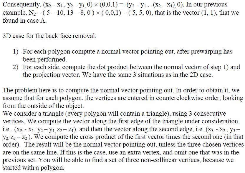
1 Hidden-Surface emoval. Here we need to discover whether an object is visible or another one obscures it. here are two fundamental approaches to remove the hidden surfaces: ) he object-space approach ) he image-space approach he object-space approach works with objects. It takes one object (polygon) and compares it pair wise with all the other polygons. hen we are done, we know the part of this polygon that is visible, we draw it, and then we proceed to work with the next polygon, doing the same. hen we are left with two remaining polygons, we compare them, and then we draw the visible parts. In the image-space approach, for every pixel we consider the intersection of all the planes of the objects with the ray emanating from that pixel. e take the intersection closest to the projection plane, and we draw that pixel according to the characteristics of the polygon whose intersection we are drawing. e are going to study the following algorithms: ) ack face removal ) Z-buffer ) Painter s ) Scan line 5) arnock s area subdivision ack face removal algorithm. As usual we start working in D, and the generalization to D is quite simple. e note that this algorithm will only work for convex polygons for the D case, and for convex polyhedra in the D case. esides we work with the orthographic projection, because we can apply the algorithm after the prewarping has been done (If we change the direction of projection, the algorithm will still work). In this algorithm we determine which faces (edges in the case of D) are in front and which are in back. e can make this determination looking at each edge independently. ack face removal algorithm: I For each edge of the polygon, compute a normal vector pointing out. See figure
2 II For each edge, compute the angle between the normal vector computed in step I, and the direction of projection, given by the dot product of these two vectors. Since we are considering a parallel projection, we have a single projection vector. e have then x, y ) ( x, y ) x x + y y x. cosθ. See figure ( y hen the rule is: If cos θ >, the edge is visible If cos θ <, the edge is invisible If cos θ, we don t care. If the projection is not orthogonal to the projection line, the same holds. Example: Case A. Consider the triangle with vertices (,), (5,) and (, 8). he direction of projection P is (,-, ), in homogeneous coordinates. See figure e need to find the normal vectors N, N, and N. For N we find the line going 8 through (, ) and (,8). m, and therefore y ( x ). In other words, (y ) + (x ). So the direction of this line is (, -, ) and the direction of the normal is (-, -, ). his implies that N is the vector (-, - ). Similar computations for the other two cases obtain that N is the vector (,) and N is the vector (-,). herefore, N P (-, - ) (, -). Edge visible
3 N P (, ) (, -) -. Edge invisible N P (-, ) (, -) -. Edge invisible Case : Suppose we change the direction of projection to Q (, -) (Oblique projection). e use prewarping.. e distort the triangle through prewarping. he 5,,],,] new coordinates will be: [ ] [ ] [,,] ] [,,] ] before, and we obtain:,,] N [ ], N [,,] ] and [,8,] ] e now do the orthographic projection: [,8,] ]. e find the normal vectors as, N [,,] ]. herefore, N P (-, - ) (, -). N P (, -) (, -). N P (-, ) (, -) -. Edge visible Edge visible Edge invisible emark: e can improve the process of finding the normal to each edge. he vertices are listed in counterclockwise order. e consider two vertices P and P, with coordinates (x, y ) and (x, y ). e compute the two vectors (x - x, y y, ) and (x - x, y y, ) and we perform the cross product of each of them with respect to the vector (,,). y the right hand site rule, the vector needed to obtain the outside normal vector, N, is going from (x, y ) to (x, y ). See figure
4
5 Initialize both buffers: Distance buffer to IGVAUE (a large negative constant) Color buffer to the background color. For each polygon we specify: a) Vertices b) Edge color c) Fill-in color e keep the pseudo-distance information of every projected point, since it is given by the prewarping transformation. e go over each polygon at the pixel level (image space). e find the distance from the point in the polygon that is going to be projected into a particular pixel, and we compare this distance with the distance in the z buffer. If the new distance is less than the distance we have in the buffer, update the z buffer and replace the color in the buffer color with the new color given by the polygon. If the distance is greater than the one in the z buffer, we have already processed a closer polygon, and we skip the point in the polygon. If the distances are equal, a decision should be made following a predetermined criterion. hen all the polygons have been scanned, draw the screen using the information in the color buffer. et s work with one polygon, because the process is the same for all of them. e use an incremental approach going from pixel to pixel. ) Find the equation of the plane in which the polygon lies (if we have not already found it). e work with the prewarped polygon, and take the first three non-collinear vertices, with coordinates (x, y, z ), (x, y, z ) and (x, y, z ) to compute the prewarped normal, N (x - x, y y, z z ) (x - x, y y, z z ) ((y y ).(z z ) (y y ).( z z ), (x - x ).(z z ) (x - x ).( z z ), (x - x ).( y y ) (x - x ),(y y ) ). aking any point in the plane, with coordinates (x, y, z), we determine the equation of the plane by writing the equation (x - x, y - y, z - z ) N. From this equation we obtain the equation of the plane A x + y + C z + D, where A y (z z ) + y (z z ) + y (z z ) z (x x ) + z (x x ) + z (x x ) C x (y y ) + x (y y ) + x (y y ) D - x (y z y z ) - x (y z - y z ) - x (y z y z ) hese coefficients are the same for the whole polygon. ) Using a polygon fill algorithm, we can cover all the pixels inside the polygon. Now for every pixel on the screen, with coordinates (x, y), we must find the corresponding world coordinates (x w, y w, z w ) of the prewarped point that goes into this pixel. his is done
6 using the inverse of the window-to-ndc-to-screen transformation first, and then the equation of the plane. e know that x NDC x w V V + V V y NDC y w V V + V V and x round ( MaxX x NDC ) y round ( - MaxY yndc + MaxY). Solving for x w and y w, we obtain x w x NDC y w y NDC - V - V - V V - V V V V V V V V Now we find the values of x NDC and y NDC by removing the round function from the formulas relating x NDC and y NDC with x and y: x x NDC MaxX y NDC ( MaxY y) * MaxY * Finally, we obtain x w y w - V V - V V x V V - MaxX V V ( MaxY y) V V - MaxY V V et us assume, for the sake of simplicity, that we have the whole screen, V, V, V, V.75. herefore we can write:
7 - x w x + MaxX ( MaxY y) y w ( - ) + MaxY MaxY y + et s call q the value of - MaxX, i.e. q - MaxX Now, since we know the point (x w, y w ), we know that the z coordinate of this point is the pseudo-depth, which can be found using the equation of the plane A x + y + C z + D, that we found before. Ax herefore, z w (x w, y w ) - consideration. + y C w w + D, is the depth of that polygon for the pixel under As we move to the next pixel on the screen, x is incremented by, and the y remains the same, since we are dealing with the scan line. ut an increment of for x on the screen corresponds to an increment of q for x w. Now consider two points P and Q on the polygon, and consequently on the plane. et (x p, y p, z p ) and (x q, y q, z q ) be the corresponding coordinates of these points. e define Δx x p - x q Δy y p y q Δz z p z q hen the equation of the plane can be written in differential form as A Δx + Δy + C Δz. Since this equation is in window coordinates, and the scan line is a line with constant value of y (the scan value), when we increment the value of x by a unit, the y w does not change, and the x w changes by q. herefore we can write that when moving on the scan line from one pixel to the next, the pseudo-depth changes according to the formula: A Δx w + Δy w + C Δz w. ut Δy w, and Δx w q. So Δz w - q C A, that is a constant, i.e. the depth of a certain pixel changes by a constant amount when stepping from one pixel to the next one in the same scan line. esides, this constant is the same for the entire polygon. herefore we need to compute the depth corresponding to the starting pixel on any scan line, and then add the fixed amount to compute the depths of the rest of the pixels on that scan line.
8 Example: Suppose that we have a resolution of on the monitor. Assume that the viewport covers the whole screen and the real world window is given by -, -.5,,, N -.5 and F -. Find the pseudo-depth corresponding to the pixel (,5) when the real world triangle (,, -), (,, -), (,, -) is being projected onto the xy-plane using the projection with center (-,,, ) H. Prewarping matrix. e transform the triangle 6 So the new triangle is A ( -.5,, -.5), ( -,.5, -.5) and C (-,.5, -.75). In order to find the plane where the triangle lives, we compute the normal, i.e. ( A ) ( C ) ( -.5,.5, ) ( -,, -.5) (-.5, -.5,.5). herefore the equation of the plane is (x +, y.5, z +.75) (-, -, ). In standard notation we have z.5 x +.5 y.75. e must prewarp the real world window, to check if the point is outside the far or near plane. So we consider a point on the far plane and another on the near plane (because points on the same z-plane, go to the same new z-plane on the pseudo-depth).
9 So the distorted window lies between the new N - and the new F - 5. So to compute the world coordinates corresponding to the screen coordinates x, y 5, we have x w MaxX - x + ) ( ) ( y w MaxY y + ) ( z w his point lies inside the distorted world window. Painters algorithm. Here we don t work pixel by pixel as before, but we work with the set of polygons. e first paint the furthest polygon, and then we remove it. e then work with the next furthest one. hen we are done with all of them, the drawing is finished. In order to find the furthest polygon, we first need to sort the polygons. Sorting: ) For each polygon determine the deepest point (the most negative value of the pseudodepth z). Sort the polygons using the order of the deepest point: A > D >. See figure.
10 et s call S the surface with the deepest point. S is a candidate to be drawn first. ) Compare S to the other surfaces in the list to determine if there are any overlaps in depth. Use lowest and greatest value of z to make this comparison. If no depth-overlap occurs, the surface S is drawn and the process is repeated for the next surface in the list. As far as no overlap occurs, we may keep going until we finish with all the surfaces on the list Note that every time a surface is drawn, it is eliminated from the list. If an overlap occurs, we need to make additional comparisons to determine whether or not a reordering is necessary. If any of the following tests is true, no reordering is needed. e list the set of comparisons, in order of difficulty: A) No x-overlap ) No y-overlap See the following figure in D, to understand the previous two cases:
11 C) Surface S is on the outside of the overlapping surface, relative to the view plane. Or S is in the back of the plane generated by S. See figure In order to determine this condition, we find the equation of the plane containing S : A x + y + C z + D. e know that using one vertex P (p, p, p ) on S and the normal to the surface pointing towards the view plane we can compute the equation of the plane. See figure.
12 he normal was computed using the back face algorithm If the normal were pointing away from the view plane, that face would have been removed by the back face algorithm. Equation of the plane containing S : (X P) N ', i.e. (x - p ) N x + (y p ) N y + (z p ) N z. N x x + N y y + N z z + D Consider the function f(x, y, z) N x x + N y y + N z z + D. For any point (x, y, z ) in the plane generated by S, we have that f(x, y, z ). herefore N x p + N y p + N z p + D ake a vertex Q (q, q, q ) on S. (Q P) N ' <. In other words, (q - p ) N x + (q p ) N y + (q p ) N z <. herefore N x q + N y q + N z q + D <. If this last condition is true for every vertex of the polygon S, this polygon is on the outside of the surface S. D) Surface S is in the inside of surface S, relative to the view plane. S is in front of the plane generated by S. See figure.
 he projections of the two surfaces onto the view plane do not overlap.")
13 Using a technique similar to the one in case C), S is on the inside of surface S if for every vertex in S, let s call it Q (q, q, q ), the following condition holds: N x q + N y q + N z q + D >. here N x x + N y y + N z z + D is the equation of the plane generated by S. E) he projections of the two surfaces onto the view plane do not overlap. Although the surfaces have overlapping x and y boundaries, the actual projection of the two surfaces does not overlap. See figure. If everything fails, we interchange the order of S and S. See the next figure for an example of this case, because although S has the deepest depth, it will obscure S.
14 . herefore S is now at the top of the list, and we should start comparing it with all the elements in the list. Note that it is possible for this algorithm to go into an infinite loop if two or more surfaces alternately obscure each other. See the next figure for an example of this situation: You may check that all the previous tests fail. o avoid such loops, flag any surface that has been reordered. If an attempt is made to switch that surface a second time, we must divide it into two parts, using the intersection line of the two planes under consideration. he original surface is replaced by these two new surfaces, and the process is started again with this new augmented list. arnock s area subdivision his is an image-space method. It tries to determine those view areas that represent part of a visible single surface. he methods is applied by successively dividing the total

15 viewing area into smaller and smaller rectangles, until each small area is the projection of part of a single visible surface or no surface at all. he idea is to check which area is part of a single surface, or it too complex to be analyzed. In order to do this, when studying a particular area, we classify the surface into four classes. Surrounding surface: One completely contains the area Intersecting surface: One that intersects the area Inside surface: One that is completely inside the area Outside surface: One that is completely outside the area See figure Consider the surfaces that project into this area. e can use these categories of surfaces. to see what we need to do. No need to subdivide the area if one of the following conditions is true i) All surfaces are outside surfaces. Use background color for this area ii) Only one intersecting or one inside surface is in the area. Use background color for the area, and then the fill in the part of the intersecting or inside surface. iii) Only one surrounding surface. Use color of surrounding surface. iv) A surrounding surface obscures all other surfaces within the area boundaries. (ook at the previous algorithm). Use the area with color of surrounding surface. Check depth of the all the planes of the surfaces at the four corners of the area, to determine if one obscures all other surfaces. If none of the cases resolves the problem, the area is subdivided into equal areas, and each area s surfaces are examined as before. he process stops when there is no more possible subdivision. he closest surface that is visible from that pixel determines the color of the pixel.
Visible Surface Detection Methods
 Visible urface Detection Methods Visible-urface Detection identifying visible parts of a scene (also hidden- elimination) type of algorithm depends on: complexity of scene type of objects available equipment
Werner Purgathofer
 Einführung in Visual Computing 186.822 Visible Surface Detection Werner Purgathofer Visibility in the Rendering Pipeline scene objects in object space object capture/creation ti modeling viewing projection
4.5 VISIBLE SURFACE DETECTION METHODES
 4.5 VISIBLE SURFACE DETECTION METHODES A major consideration in the generation of realistic graphics displays is identifying those parts of a scene that are visible from a chosen viewing position. There
Renderer Implementation: Basics and Clipping. Overview. Preliminaries. David Carr Virtual Environments, Fundamentals Spring 2005
 INSTITUTIONEN FÖR SYSTEMTEKNIK LULEÅ TEKNISKA UNIVERSITET Renderer Implementation: Basics and Clipping David Carr Virtual Environments, Fundamentals Spring 2005 Feb-28-05 SMM009, Basics and Clipping 1
Computer Graphics II
 Computer Graphics II Autumn 2017-2018 Outline Visible Surface Determination Methods (contd.) 1 Visible Surface Determination Methods (contd.) Outline Visible Surface Determination Methods (contd.) 1 Visible
9. Visible-Surface Detection Methods
 9. Visible-Surface Detection Methods More information about Modelling and Perspective Viewing: Before going to visible surface detection, we first review and discuss the followings: 1. Modelling Transformation:
CS184 : Foundations of Computer Graphics Professor David Forsyth Final Examination
 CS184 : Foundations of Computer Graphics Professor David Forsyth Final Examination (Total: 100 marks) Figure 1: A perspective view of a polyhedron on an infinite plane. Cameras and Perspective Rendering
CS184 : Foundations of Computer Graphics Professor David Forsyth Final Examination (Total: 100 marks)
") CS184 : Foundations of Computer Graphics Professor David Forsyth Final Examination (Total: 100 marks) Cameras and Perspective Figure 1: A perspective view of a polyhedron on an infinite plane. Rendering
CS184 : Foundations of Computer Graphics Professor David Forsyth Final Examination (Total: 100 marks) Cameras and Perspective Figure 1: A perspective view of a polyhedron on an infinite plane. Rendering
Page 1. Area-Subdivision Algorithms z-buffer Algorithm List Priority Algorithms BSP (Binary Space Partitioning Tree) Scan-line Algorithms
 Scan-line Algorithms") Visible Surface Determination Visibility Culling Area-Subdivision Algorithms z-buffer Algorithm List Priority Algorithms BSP (Binary Space Partitioning Tree) Scan-line Algorithms Divide-and-conquer strategy:
Visible Surface Determination Visibility Culling Area-Subdivision Algorithms z-buffer Algorithm List Priority Algorithms BSP (Binary Space Partitioning Tree) Scan-line Algorithms Divide-and-conquer strategy:
Computer Graphics. Bing-Yu Chen National Taiwan University The University of Tokyo
 Computer Graphics Bing-Yu Chen National Taiwan University The University of Tokyo Hidden-Surface Removal Back-Face Culling The Depth-Sort Algorithm Binary Space-Partitioning Trees The z-buffer Algorithm
Computer Graphics. Bing-Yu Chen National Taiwan University
 Computer Graphics Bing-Yu Chen National Taiwan University Visible-Surface Determination Back-Face Culling The Depth-Sort Algorithm Binary Space-Partitioning Trees The z-buffer Algorithm Scan-Line Algorithm
CEng 477 Introduction to Computer Graphics Fall 2007
 Visible Surface Detection CEng 477 Introduction to Computer Graphics Fall 2007 Visible Surface Detection Visible surface detection or hidden surface removal. Realistic scenes: closer objects occludes the
Hidden Surface Removal
 Outline Introduction Hidden Surface Removal Hidden Surface Removal Simone Gasparini gasparini@elet.polimi.it Back face culling Depth sort Z-buffer Introduction Graphics pipeline Introduction Modeling Geom
8. Hidden Surface Elimination
 -04-8 Hidden Surface Elimination To eliminate edges and surfaces not visible to the viewer Two categories: Object space methods: Image space methods: deal with object definitions directly Order the surfaces
8. Hidden Surface Elimination
 8. Hidden Surface Elimination Identification and Removal of parts of picture that are not visible from a chosen viewing position. 1 8. Hidden Surface Elimination Basic idea: Overwriting Paint things in
Midterm Exam Fundamentals of Computer Graphics (COMP 557) Thurs. Feb. 19, 2015 Professor Michael Langer
 Thurs. Feb. 19, 2015 Professor Michael Langer") Midterm Exam Fundamentals of Computer Graphics (COMP 557) Thurs. Feb. 19, 2015 Professor Michael Langer The exam consists of 10 questions. There are 2 points per question for a total of 20 points. You
Midterm Exam Fundamentals of Computer Graphics (COMP 557) Thurs. Feb. 19, 2015 Professor Michael Langer The exam consists of 10 questions. There are 2 points per question for a total of 20 points. You
CSE528 Computer Graphics: Theory, Algorithms, and Applications
 CSE528 Computer Graphics: Theory, Algorithms, and Applications Hong Qin State University of New York at Stony Brook (Stony Brook University) Stony Brook, New York 11794--4400 Tel: (631)632-8450; Fax: (631)632-8334
CSE328 Fundamentals of Computer Graphics: Concepts, Theory, Algorithms, and Applications
 CSE328 Fundamentals of Computer Graphics: Concepts, Theory, Algorithms, and Applications Hong Qin Stony Brook University (SUNY at Stony Brook) Stony Brook, New York 11794-4400 Tel: (631)632-8450; Fax:
Computing Visibility. Backface Culling for General Visibility. One More Trick with Planes. BSP Trees Ray Casting Depth Buffering Quiz
 Computing Visibility BSP Trees Ray Casting Depth Buffering Quiz Power of Plane Equations We ve gotten a lot of mileage out of one simple equation. Basis for D outcode-clipping Basis for plane-at-a-time
Pipeline Operations. CS 4620 Lecture 10
 Pipeline Operations CS 4620 Lecture 10 2008 Steve Marschner 1 Hidden surface elimination Goal is to figure out which color to make the pixels based on what s in front of what. Hidden surface elimination
(Refer Slide Time 03:00)
") Computer Graphics Prof. Sukhendu Das Dept. of Computer Science and Engineering Indian Institute of Technology, Madras Lecture #30 Visible Surface Detection (Contd ) We continue the discussion on Visible
Computer Graphics Prof. Sukhendu Das Dept. of Computer Science and Engineering Indian Institute of Technology, Madras Lecture #30 Visible Surface Detection (Contd ) We continue the discussion on Visible
Visible-Surface Detection Methods. Chapter? Intro. to Computer Graphics Spring 2008, Y. G. Shin
 Visible-Surface Detection Methods Chapter? Intro. to Computer Graphics Spring 2008, Y. G. Shin The Visibility Problem [Problem Statement] GIVEN: a set of 3-D surfaces, a projection from 3-D to 2-D screen,
CS602 Midterm Subjective Solved with Reference By WELL WISHER (Aqua Leo)
") CS602 Midterm Subjective Solved with Reference By WELL WISHER (Aqua Leo) www.vucybarien.com Question No: 1 What are the two focusing methods in CRT? Explain briefly. Page no : 26 1. Electrostatic focusing
CS602 Midterm Subjective Solved with Reference By WELL WISHER (Aqua Leo) www.vucybarien.com Question No: 1 What are the two focusing methods in CRT? Explain briefly. Page no : 26 1. Electrostatic focusing
Computer Graphics: 8-Hidden Surface Removal
 Computer Graphics: 8-Hidden Surface Removal Prof. Dr. Charles A. Wüthrich, Fakultät Medien, Medieninformatik Bauhaus-Universität Weimar caw AT medien.uni-weimar.de Depth information Depth information is
The Graphics Pipeline. Interactive Computer Graphics. The Graphics Pipeline. The Graphics Pipeline. The Graphics Pipeline: Clipping
 Interactive Computer Graphics The Graphics Pipeline: The Graphics Pipeline Input: - geometric model - illumination model - camera model - viewport Some slides adopted from F. Durand and B. Cutler, MIT
Chapter 5. Projections and Rendering
 Chapter 5 Projections and Rendering Topics: Perspective Projections The rendering pipeline In order to view manipulate and view a graphics object we must find ways of storing it a computer-compatible way.
Triangle Rasterization
 Triangle Rasterization Computer Graphics COMP 770 (236) Spring 2007 Instructor: Brandon Lloyd 2/07/07 1 From last time Lines and planes Culling View frustum culling Back-face culling Occlusion culling
Computer Graphics Viewing
 Computer Graphics Viewing What Are Projections? Our 3-D scenes are all specified in 3-D world coordinates To display these we need to generate a 2-D image - project objects onto a picture plane Picture
COMP30019 Graphics and Interaction Scan Converting Polygons and Lines
 COMP30019 Graphics and Interaction Scan Converting Polygons and Lines Department of Computer Science and Software Engineering The Lecture outline Introduction Scan conversion Scan-line algorithm Edge coherence
Hidden surface removal. Computer Graphics
 Lecture Hidden Surface Removal and Rasterization Taku Komura Hidden surface removal Drawing polygonal faces on screen consumes CPU cycles Illumination We cannot see every surface in scene We don t want
THE DEPTH-BUFFER VISIBLE SURFACE ALGORITHM
 On-Line Computer Graphics Notes THE DEPTH-BUFFER VISIBLE SURFACE ALGORITHM Kenneth I. Joy Visualization and Graphics Research Group Department of Computer Science University of California, Davis To accurately
Visible Surface Detection. (Chapt. 15 in FVD, Chapt. 13 in Hearn & Baker)
") Visible Surface Detection (Chapt. 15 in FVD, Chapt. 13 in Hearn & Baker) 1 Given a set of 3D objects and a viewing specifications, determine which lines or surfaces of the objects should be visible. A
Visible Surface Detection (Chapt. 15 in FVD, Chapt. 13 in Hearn & Baker) 1 Given a set of 3D objects and a viewing specifications, determine which lines or surfaces of the objects should be visible. A
Lecture 4. Viewing, Projection and Viewport Transformations
 Notes on Assignment Notes on Assignment Hw2 is dependent on hw1 so hw1 and hw2 will be graded together i.e. You have time to finish both by next monday 11:59p Email list issues - please cc: elif@cs.nyu.edu
graphics pipeline computer graphics graphics pipeline 2009 fabio pellacini 1
 graphics pipeline computer graphics graphics pipeline 2009 fabio pellacini 1 graphics pipeline sequence of operations to generate an image using object-order processing primitives processed one-at-a-time
Notes on Assignment. Notes on Assignment. Notes on Assignment. Notes on Assignment
 Notes on Assignment Notes on Assignment Objects on screen - made of primitives Primitives are points, lines, polygons - watch vertex ordering The main object you need is a box When the MODELVIEW matrix
graphics pipeline computer graphics graphics pipeline 2009 fabio pellacini 1
 graphics pipeline computer graphics graphics pipeline 2009 fabio pellacini 1 graphics pipeline sequence of operations to generate an image using object-order processing primitives processed one-at-a-time
Two basic types: image-precision and object-precision. Image-precision For each pixel, determine which object is visable Requires np operations
 walters@buffalo.edu CSE 480/580 Lecture 21 Slide 1 Visible-Surface Determination (Hidden Surface Removal) Computationaly expensive Two basic types: image-precision and object-precision For n objects and
Today. CS-184: Computer Graphics. Lecture #10: Clipping and Hidden Surfaces. Clipping. Hidden Surface Removal
 Today CS-184: Computer Graphics Lecture #10: Clipping and Hidden Surfaces!! Prof. James O Brien University of California, Berkeley! V2015-S-10-1.0 Clipping Clipping to view volume Clipping arbitrary polygons
More Visible Surface Detection. CS116B Chris Pollett Mar. 16, 2005.
 More Visible Surface Detection CS116B Chris Pollett Mar. 16, 2005. Outline The A-Buffer Method The Scan-Line Method The Depth Sorting Method BSP Trees, Area Subdivision, and Octrees Wire-frame Visibility
Computer Science 426 Midterm 3/11/04, 1:30PM-2:50PM
 NAME: Login name: Computer Science 46 Midterm 3//4, :3PM-:5PM This test is 5 questions, of equal weight. Do all of your work on these pages (use the back for scratch space), giving the answer in the space
3D Object Representation
 3D Object Representation Object Representation So far we have used the notion of expressing 3D data as points(or vertices) in a Cartesian or Homogeneous coordinate system. We have simplified the representation
Orthogonal Projection Matrices. Angel and Shreiner: Interactive Computer Graphics 7E Addison-Wesley 2015
 Orthogonal Projection Matrices 1 Objectives Derive the projection matrices used for standard orthogonal projections Introduce oblique projections Introduce projection normalization 2 Normalization Rather
Clipping. Angel and Shreiner: Interactive Computer Graphics 7E Addison-Wesley 2015
 Clipping 1 Objectives Clipping lines First of implementation algorithms Clipping polygons (next lecture) Focus on pipeline plus a few classic algorithms 2 Clipping 2D against clipping window 3D against
Institutionen för systemteknik
 Code: Day: Lokal: M7002E 19 March E1026 Institutionen för systemteknik Examination in: M7002E, Computer Graphics and Virtual Environments Number of sections: 7 Max. score: 100 (normally 60 is required
Identifying those parts of a scene that are visible from a chosen viewing position, and only process (scan convert) those parts
 those parts") Visible Surface Detection Identifying those parts of a scene that are visible from a chosen viewing position, and only process (scan convert) those parts Two approaches: 1. Object space methods 2. Image
Visible Surface Detection Identifying those parts of a scene that are visible from a chosen viewing position, and only process (scan convert) those parts Two approaches: 1. Object space methods 2. Image
Clipping and Intersection
 Clipping and Intersection Clipping: Remove points, line segments, polygons outside a region of interest. Need to discard everything that s outside of our window. Point clipping: Remove points outside window.
CS 4204 Computer Graphics
 CS 4204 Computer Graphics 3D Viewing and Projection Yong Cao Virginia Tech Objective We will develop methods to camera through scenes. We will develop mathematical tools to handle perspective projection.
Visible Surface Determination: Intro
 Visible Surface Determination: Intro VSD deals with determining what is visible in a scene 2 general approaches are used: 1. Object precision Older approach Designed for vector displays Determines visibility
Computer Graphics. Lecture 9 Hidden Surface Removal. Taku Komura
 Computer Graphics Lecture 9 Hidden Surface Removal Taku Komura 1 Why Hidden Surface Removal? A correct rendering requires correct visibility calculations When multiple opaque polygons cover the same screen
VISIBILITY & CULLING. Don t draw what you can t see. Thomas Larsson, Afshin Ameri DVA338, Spring 2018, MDH
 VISIBILITY & CULLING Don t draw what you can t see. Thomas Larsson, Afshin Ameri DVA338, Spring 2018, MDH Visibility Visibility Given a set of 3D objects, which surfaces are visible from a specific point
BSP Trees. Chapter Introduction. 8.2 Overview
 Chapter 8 BSP Trees 8.1 Introduction In this document, we assume that the objects we are dealing with are represented by polygons. In fact, the algorithms we develop actually assume the polygons are triangles,
CS 498 VR. Lecture 18-4/4/18. go.illinois.edu/vrlect18
 CS 498 VR Lecture 18-4/4/18 go.illinois.edu/vrlect18 Review and Supplement for last lecture 1. What is aliasing? What is Screen Door Effect? 2. How image-order rendering works? 3. If there are several
Visibility: Z Buffering
 University of British Columbia CPSC 414 Computer Graphics Visibility: Z Buffering Week 1, Mon 3 Nov 23 Tamara Munzner 1 Poll how far are people on project 2? preferences for Plan A: status quo P2 stays
Drawing the Visible Objects
 Drawing the Visible Objects We want to generate the image that the eye would see, given the objects in our space How do we draw the correct object at each pixel, given that some objects may obscure others
Einführung in Visual Computing
 Einführung in Visual Computing 186.822 Rasterization Werner Purgathofer Rasterization in the Rendering Pipeline scene objects in object space transformed vertices in clip space scene in normalized device
SE Mock Online Test 1-CG
 SE Mock Online Test 1-CG 1. Email address * 2. 1. For gentle slope line, slope m is -1
Visible-Surface Detection 1. 2IV60 Computer graphics set 11: Hidden Surfaces. Visible-Surface Detection 3. Visible-Surface Detection 2
 Visible-urface Detection IV60 omputer graphics set : Hidden urfaces Problem: Given a scene and a projection, what can we see? Jack van Wijk TU/e Visible-urface Detection Terminology: Visible-surface detection
FROM VERTICES TO FRAGMENTS. Lecture 5 Comp3080 Computer Graphics HKBU
 FROM VERTICES TO FRAGMENTS Lecture 5 Comp3080 Computer Graphics HKBU OBJECTIVES Introduce basic implementation strategies Clipping Scan conversion OCTOBER 9, 2011 2 OVERVIEW At end of the geometric pipeline,
Hidden Surface Elimination: BSP trees
 Hidden Surface Elimination: BSP trees Outline Binary space partition (BSP) trees Polygon-aligned 1 BSP Trees Basic idea: Preprocess geometric primitives in scene to build a spatial data structure such
CSCI 4620/8626. Coordinate Reference Frames
 CSCI 4620/8626 Computer Graphics Graphics Output Primitives Last update: 2014-02-03 Coordinate Reference Frames To describe a picture, the world-coordinate reference frame (2D or 3D) must be selected.
Pipeline Operations. CS 4620 Lecture 14
 Pipeline Operations CS 4620 Lecture 14 2014 Steve Marschner 1 Pipeline you are here APPLICATION COMMAND STREAM 3D transformations; shading VERTEX PROCESSING TRANSFORMED GEOMETRY conversion of primitives
INTRODUCTION TO COMPUTER GRAPHICS. It looks like a matrix Sort of. Viewing III. Projection in Practice. Bin Sheng 10/11/ / 52
 cs337 It looks like a matrix Sort of Viewing III Projection in Practice / 52 cs337 Arbitrary 3D views Now that we have familiarity with terms we can say that these view volumes/frusta can be specified
(Refer Slide Time 05:03 min)
") Computer Graphics Prof. Sukhendu Das Dept. of Computer Science and Engineering Indian Institute of Technology, Madras Lecture # 27 Visible Surface Detection (Contd ) Hello and welcome everybody to the
Computer Graphics Prof. Sukhendu Das Dept. of Computer Science and Engineering Indian Institute of Technology, Madras Lecture # 27 Visible Surface Detection (Contd ) Hello and welcome everybody to the
Lecture 8 Ray tracing Part 1: Basic concept Yong-Jin Liu.
 Fundamentals of Computer Graphics Lecture 8 Ray tracing Part 1: Basic concept Yong-Jin Liu liuyongjin@tsinghua.edu.cn Material by S.M.Lea (UNC) Goals To set up the mathematics and algorithms to perform
Z- Buffer Store the depth for each pixel on the screen and compare stored value with depth of new pixel being drawn.
 Andrew Lewis - Graphics Revision Keywords PIXEL FRAME BUFFER memory of the screen VIDEO - SCREEN - WINDOW - POLYGON filled area bound by straight lines SPLINE bit of wood used by draughtsmen to draw curves
3D Polygon Rendering. Many applications use rendering of 3D polygons with direct illumination
 Rendering Pipeline 3D Polygon Rendering Many applications use rendering of 3D polygons with direct illumination 3D Polygon Rendering What steps are necessary to utilize spatial coherence while drawing
For each question, indicate whether the statement is true or false by circling T or F, respectively.
 True/False For each question, indicate whether the statement is true or false by circling T or F, respectively. 1. (T/F) Rasterization occurs before vertex transformation in the graphics pipeline. 2. (T/F)
CMSC427: Computer Graphics Lecture Notes Last update: November 21, 2014
 CMSC427: Computer Graphics Lecture Notes Last update: November 21, 2014 TA: Josh Bradley 1 Linear Algebra Review 1.1 Vector Multiplication Suppose we have a vector a = [ x a y a ] T z a. Then for some
Chapter - 2: Geometry and Line Generations
 Chapter - 2: Geometry and Line Generations In Computer graphics, various application ranges in different areas like entertainment to scientific image processing. In defining this all application mathematics
S U N G - E U I YO O N, K A I S T R E N D E R I N G F R E E LY A VA I L A B L E O N T H E I N T E R N E T
 S U N G - E U I YO O N, K A I S T R E N D E R I N G F R E E LY A VA I L A B L E O N T H E I N T E R N E T Copyright 2018 Sung-eui Yoon, KAIST freely available on the internet http://sglab.kaist.ac.kr/~sungeui/render
Shadows in Computer Graphics
 Shadows in Computer Graphics Steven Janke November 2014 Steven Janke (Seminar) Shadows in Computer Graphics November 2014 1 / 49 Shadows (from Doom) Steven Janke (Seminar) Shadows in Computer Graphics
CS4620/5620: Lecture 14 Pipeline
 CS4620/5620: Lecture 14 Pipeline 1 Rasterizing triangles Summary 1! evaluation of linear functions on pixel grid 2! functions defined by parameter values at vertices 3! using extra parameters to determine
Three Dimensional Geometry. Linear Programming
 Three Dimensional Geometry Linear Programming A plane is determined uniquely if any one of the following is known: The normal to the plane and its distance from the origin is given, i.e. equation of a
Hidden Line and Surface
 Copyright@00, YZU Optimal Design Laboratory. All rights resered. Last updated: Yeh-Liang Hsu (00--). Note: This is the course material for ME550 Geometric modeling and computer graphics, Yuan Ze Uniersity.
Models and The Viewing Pipeline. Jian Huang CS456
 Models and The Viewing Pipeline Jian Huang CS456 Vertex coordinates list, polygon table and (maybe) edge table Auxiliary: Per vertex normal Neighborhood information, arranged with regard to vertices and
Pipeline Operations. CS 4620 Lecture Steve Marschner. Cornell CS4620 Spring 2018 Lecture 11
 Pipeline Operations CS 4620 Lecture 11 1 Pipeline you are here APPLICATION COMMAND STREAM 3D transformations; shading VERTEX PROCESSING TRANSFORMED GEOMETRY conversion of primitives to pixels RASTERIZATION
CS 488. More Shading and Illumination. Luc RENAMBOT
 CS 488 More Shading and Illumination Luc RENAMBOT 1 Illumination No Lighting Ambient model Light sources Diffuse reflection Specular reflection Model: ambient + specular + diffuse Shading: flat, gouraud,
Incremental Form. Idea. More efficient if we look at d k, the value of the decision variable at x = k
 Idea 1 m 0 candidates last pixel Note that line could have passed through any part of this pixel Decision variable: d = x(a-b) d is an integer d < 0 use upper pixel d > 0 use lower pixel Incremental Form
CSE 167: Lecture #5: Rasterization. Jürgen P. Schulze, Ph.D. University of California, San Diego Fall Quarter 2012
 CSE 167: Introduction to Computer Graphics Lecture #5: Rasterization Jürgen P. Schulze, Ph.D. University of California, San Diego Fall Quarter 2012 Announcements Homework project #2 due this Friday, October
Intro to Modeling Modeling in 3D
 Intro to Modeling Modeling in 3D Polygon sets can approximate more complex shapes as discretized surfaces 2 1 2 3 Curve surfaces in 3D Sphere, ellipsoids, etc Curved Surfaces Modeling in 3D ) ( 2 2 2 2
CS488. Visible-Surface Determination. Luc RENAMBOT
 CS488 Visible-Surface Determination Luc RENAMBOT 1 Visible-Surface Determination So far in the class we have dealt mostly with simple wireframe drawings of the models The main reason for this is so that
Example Examination 2IV
 Example Examination IV60-04071 (translated version IV10 4 july 01, 14:00-17:00) This examination consist of four questions with in total 16 subquestion. Each subquestion weighs equally. In all cases: EXPLAIN
Class of Algorithms. Visible Surface Determination. Back Face Culling Test. Back Face Culling: Object Space v. Back Face Culling: Object Space.
 Utah School of Computing Spring 13 Class of Algorithms Lecture Set Visible Surface Determination CS56 Computer Graphics From Rich Riesenfeld Spring 13 Object (Model) Space Algorithms Work in the model
PESIT Bangalore South Campus Hosur road, 1km before Electronic City, Bengaluru -100 Department of Computer Science
 INTERNAL ASSESSMENT TEST 2 Solution Date : 30.03.15 Max Marks : 50 Subject & Code : Computer Graphics and Visualization/10CS65 Section : A, B and C Name of faculty : Ms. Sarasvathi V/ Ms. Archana Time
Revision Problems for Examination 2 in Algebra 1
 Centre for Mathematical Sciences Mathematics, Faculty of Science Revision Problems for Examination in Algebra. Let l be the line that passes through the point (5, 4, 4) and is at right angles to the plane
CS 130 Exam I. Fall 2015
 S 3 Exam I Fall 25 Name Student ID Signature You may not ask any questions during the test. If you believe that there is something wrong with a question, write down what you think the question is trying
UNIT 2 GRAPHIC PRIMITIVES
 UNIT 2 GRAPHIC PRIMITIVES Structure Page Nos. 2.1 Introduction 46 2.2 Objectives 46 2.3 Points and Lines 46 2.4 Line Generation Algorithms 48 2.4.1 DDA Algorithm 49 2.4.2 Bresenhams Line Generation Algorithm
Geometry. Zachary Friggstad. Programming Club Meeting
 Geometry Zachary Friggstad Programming Club Meeting Points #i n c l u d e typedef complex p o i n t ; p o i n t p ( 1. 0, 5. 7 ) ; p. r e a l ( ) ; // x component p. imag ( ) ; // y component
Game Architecture. 2/19/16: Rasterization
 Game Architecture 2/19/16: Rasterization Viewing To render a scene, need to know Where am I and What am I looking at The view transform is the matrix that does this Maps a standard view space into world
Lecture 3 Sections 2.2, 4.4. Mon, Aug 31, 2009
 Model s Lecture 3 Sections 2.2, 4.4 World s Eye s Clip s s s Window s Hampden-Sydney College Mon, Aug 31, 2009 Outline Model s World s Eye s Clip s s s Window s 1 2 3 Model s World s Eye s Clip s s s Window
Rasterization Overview
 Rendering Overview The process of generating an image given a virtual camera objects light sources Various techniques rasterization (topic of this course) raytracing (topic of the course Advanced Computer
2D and 3D Transformations AUI Course Denbigh Starkey
 2D and 3D Transformations AUI Course Denbigh Starkey. Introduction 2 2. 2D transformations using Cartesian coordinates 3 2. Translation 3 2.2 Rotation 4 2.3 Scaling 6 3. Introduction to homogeneous coordinates
CS Computer Graphics: Hidden Surface Removal
 CS 543 - Computer Graphics: Hidden Surface Removal by Robert W. Lindeman gogo@wpi.edu (with help from Emmanuel Agu ;-) Hidden Surface Removal Drawing polygonal faces on screen consumes CPU cycles We cannot
Answers to practice questions for Midterm 1
 Answers to practice questions for Midterm Paul Hacking /5/9 (a The RREF (reduced row echelon form of the augmented matrix is So the system of linear equations has exactly one solution given by x =, y =,
Rasterization. MIT EECS Frédo Durand and Barb Cutler. MIT EECS 6.837, Cutler and Durand 1
 Rasterization MIT EECS 6.837 Frédo Durand and Barb Cutler MIT EECS 6.837, Cutler and Durand 1 Final projects Rest of semester Weekly meetings with TAs Office hours on appointment This week, with TAs Refine
Intersection of an Oriented Box and a Cone
 Intersection of an Oriented Box and a Cone David Eberly, Geometric Tools, Redmond WA 98052 https://www.geometrictools.com/ This work is licensed under the Creative Commons Attribution 4.0 International
521493S Computer Graphics Exercise 1 (Chapters 1-3)
") 521493S Computer Graphics Exercise 1 (Chapters 1-3) 1. Consider the clipping of a line segment defined by the latter s two endpoints (x 1, y 1 ) and (x 2, y 2 ) in two dimensions against a rectangular
521493S Computer Graphics Exercise 1 (Chapters 1-3) 1. Consider the clipping of a line segment defined by the latter s two endpoints (x 1, y 1 ) and (x 2, y 2 ) in two dimensions against a rectangular
CS452/552; EE465/505. Clipping & Scan Conversion
 CS452/552; EE465/505 Clipping & Scan Conversion 3-31 15 Outline! From Geometry to Pixels: Overview Clipping (continued) Scan conversion Read: Angel, Chapter 8, 8.1-8.9 Project#1 due: this week Lab4 due:
MODULE - 4. e-pg Pathshala
 e-pg Pathshala MODULE - 4 Subject : Computer Science Paper: Computer Graphics and Visualization Module: Midpoint Circle Drawing Procedure Module No: CS/CGV/4 Quadrant 1 e-text Before going into the Midpoint
INTRODUCTION TO COMPUTER GRAPHICS. cs123. It looks like a matrix Sort of. Viewing III. Projection in Practice 1 / 52
 It looks like a matrix Sort of Viewing III Projection in Practice 1 / 52 Arbitrary 3D views } view volumes/frusta spec d by placement and shape } Placement: } Position (a point) } look and up vectors }