Chapter 8 Three-Dimensional Viewing Operations
|
|
|
- Brian Bradley
- 6 years ago
- Views:
Transcription


1 Projections Chapter 8 Three-Dimensional Viewing Operations Figure 8.1 Classification of planar geometric projections Figure 8.2 Planar projection

2 Figure 8.3 Parallel-oblique projection Figure 8.4 Orthographic projection Figure 8.5 Axonometric projection


3 Figure 8.6 Perspective projection Figure 8.7 Multiview orthographic projection representation Figure 8.8 Orthographic projection of a point on the xy plane
 The indicated front view is a projection on the xy plane. 2 1 2 2 1 2 1 1 2 1 * 2 2 1 Based on Eq. 8.")
4 Figure 8.9 Example 8.1 Example 8.1 Given an object as shown in Figure8.9, find its front and side orthographic projections in he directions indicated by the arrows. Solution (a) The indicated front view is a projection on the xy plane * Based on Eq. 8.1, the matrix of points becomes P = xy The projection is as shown in Figure 8.1a.

5 Figure 8.1 Result of example 8.1 (b) The side view is obtained through an orthographic projection onto the yz plane * Based on Eq. 8.2, the matrix of points becomes P = yz The projection is as shown in Figure 8.1b. Orthographic projections can be used to solve other types of problems. For example, in Figure 8.11, it may be necessary to have the inclined surface projected on the xy plane in its exact shape, without distortion.


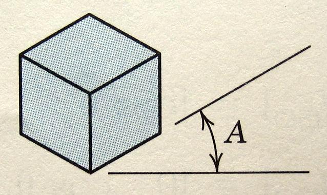
6 Figure 8.11 Axonometric Projections (the most common used in engineering) Isometric Projection: All three axes are equally foreshortened when projected. Figure 8.12 Isometric axes Figure 8.13 Transformations required to obtain an isometric projection
7
8


![8.5. cosθy sinθysinθx * cosθ x P [ P][ MISO ] [ P]](/docs-images/74/71332479/images/9-4.jpg "= = sinθy sinθxcosθy 1 For the given valued of θ x")
9 The forshorten factor: Example 8.2 Determine the isometric projection of the block described in Figure 8.9, for θ = 45 o, and θ = x o. [Solution] The solution is obtained with Eq cosθy sinθysinθx * cosθ x P [ P][ MISO ] [ P] = = sinθy sinθxcosθy 1 For the given valued of θ x and θ y, this becomes:

10 * P = , * P = Figure 8.16 Result of Example 8.2 Trimetric Projection: The transformation matrix causes pure rotation. Thus, the coordinate axes remain orthogonal when projected. Dimentric Projection: Two of the three axes are equally foreshortened when projected. The length of receding axis is given a specific foreshorten value. Example: After projection, two unit vectors of x and y axes are equally foreshorten, and the length of unit vector of z axis becomes half (or <foreshorten factor<1), therefore, we gain θ x = 2.75, θ y =

.")
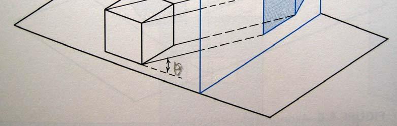
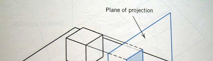
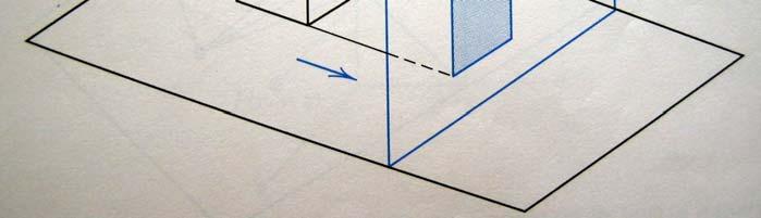
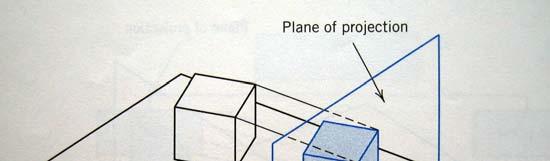
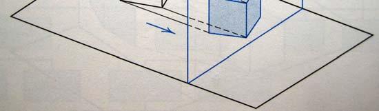
11 Oblique Projection (Shearing transformation matrix) The object is customarily positioned so that one of its principal faces is parallel to the plane of projection. This principal face appears in its true size and shape on the plane of projection. The three main axes of an oblique projection appear such that two of them are orthogonal in the plane of the paper, and the receding axis is oriented at any convenient angle (usually from 15 to 45 for proper representation of the object). Transformations l gives the foreshortening ratio of any line perpendicular to the z = plane, after projection. θ is the angle between the projection and the horizontal axis.
12 1. Shearing of the object in space in a direction parallel to the plane of projection. 2. Orthographic projection onto the plane of projection. Special cases of oblique: Cavalier and Cabinet projection Cavalier Projection : Two axes appear perpendicular and are not foreshortened; the third axis is inclined with respect to the horizontal and is not foreshortened (l = 1). It is the result of projecting rays from the object to the picture plane at a 45 angle to the plane. Cabinet Projection: Same as Cavalier projection, only the third axis is foreshortened by a factor of 1/2 ( l = 1/2). The most commonly used value for θ in Cabinet projection are 3 to 45. Oblique projections have been useful in representing objects with curved features that can be placed on the plane of projection parallel to the observer.
, ( 1,, 4 ), ( 2,,5 ), ( 4,,3) P P P P 1 2 3 4 Find the oblique cavalier projection onto a viewing surface in the z = plane.")
13 Example 8.3 A tetrahedron is define by the coordinates of its vertices, as ( 3, 4, ), ( 1,, 4 ), ( 2,,5 ), ( 4,,3) P P P P Find the oblique cavalier projection onto a viewing surface in the z = plane. The angle between the z axis and the horizontal should be 45 o in the projection. [Solution] The oblique matrix is given in Eq For cavalier projections, l = 1, and the matrix, with θ = 45 o, becomes z = 5 The transformed coordinates of the original tetrahedron are * P = = cp *, P = Perspective Projections 1-point perspective projection The perspective projection of P(x,y,z) onto the xy plane, P*(x*,y*,), with the center of projection a distance Z cp along the Z axis. Figure 8.19 Perspective projection of point P on the xy plane


14 Figure 8.2 View along y axis 1. Center of projection on the x-axis 2. Center of projection on the y-axis
15 3. Center of projection on the z-axis 2-point perspective projection 3-point perspective projection Example 8.4 Find the perspective projection of the tetrahedron given in Example 8.3 onto a projection plane at z =. The center of projection should be located at z cp = 5. [Solution] Equation 8.28 is used in the solution of this problem. The projected points are * P [ P][ M ] = PER = 1, * P = = Figure 8.22 shows the result of this projection.
![Figure 8.22 Perspective projection of tetrahedron on xy plane Vanishing Points The perspective transformation of a point located at infinity on the z axis can be represented as [ 1 ].](/docs-images/74/71332479/images/16-2.jpg "An infinite point can be represented as [x y z ].")
16 Figure 8.22 Perspective projection of tetrahedron on xy plane Vanishing Points The perspective transformation of a point located at infinity on the z axis can be represented as [ 1 ]. An infinite point can be represented as [x y z ]. Applying the perspective transformation to this point yields Vanishing point at [ 1/t 1] The two vanishing points are [1/r 1], [ 1/s 1].


17 Special Techniques Two-point perspective projection The cube is rotated by θ about the y axis and translated by [ m n], before a 1-point perspective projection onto the z = plane, with center of projection along the z axis.
.")
18 Three-point perspective projection The cube is first rotated about the y axis and then about the x axis, before applying the same perspective projection. Example 8.5 For the unit cube shown in Figure 8.24, determine the 2-point perspective projection obtained by rotating the cube 3 o about the y axis and translating it by (, 3, -3). The center of projection is at (,, 2) [Solution] Two-point perspective projection is applied to the point matrix of the cube, as follows: * P = * , P =,

 and (-1.155, ), respectively. Figure 8.")
19 * P = = Two vanish points along x- and z-axis, they are (3.464, ) and (-1.155, ), respectively. Figure 8.25 Two-point perspective projection of unit cube, obtained through a combined transformation

20 The Viewing Pipeline (PHiGS transformation pipeline) Figure 8.26 PHiGS transformation pipeline The viewing process for three-dimensional models is analogous to a camera taking pictures from different positions in space and in various orientations. To define the position of the camera in space, it is necessary to establish a new

 defined in world coordinates as a")
 in the normal direction to the view")
. Figure 8.")
21 coordinate system, the Viewing Reference Coordinate (VRC) system, which will be centered at the window. Three parameters are necessary to define the VRC. 1. the View Reference Point (VRP) defined in world coordinates as a point in the direction of which the camera is looking. 2. the View Plane Normal (VPN) in the normal direction to the view plane, defining its orientation. 3. the up direction for the camera. The View-Up Vector (VUP, vector V). Figure 8.27 Camera analogy to the viewing process Figure 8.28 Camera viewfinder corresponds to the window

 to")

22 Figure 8.29 Establishing the Viewing Reference Coordinate (VRC) system Window in VRC is (,) to (1,1) Normalized window Figure 8.3 Effect on the image of a change in the direction of the VUP

 A sequence of transformations are list below. 1. Translate the view reference point to the WC origin.")
23 To create a view of an object by user PHIGS uses a set of default specifications to represent the viewing parameters as follows: Figure 8.31 PHIGS default viewing parameters VRP in WC (,, ) VPN in WC (,, 1) VUP in WC (, 1, ) Window in VRC (, 1,, 1) A sequence of transformations are list below. 1. Translate the view reference point to the WC origin.


24 2. Rotate about the x w axis so that N falls on the x w z w plane. 3. Rotate about the y w axis, so that N coincides with z w. 4. Rotate about z w so that all axes coincide. T = [ T ][ T ] [ T ] [ T ] TR R X R Y R Z
 determine a view volume. Figure 8.")

 and back (yon) planes defining a finite section of the view volumes The appropriate viewing parameters")
25 View Volumes (Front/Side/Top Views creation) The position of the window in the view plane and the type of projection (parallel or perspectives) determine a view volume. Figure 8.32 view volumes for perspective and parallel projections For parallel projection, the Projection Reference Point (PRP) determines the direction of projection. For perspective projections, the PRP defines the center of projection. Figure 8.31 Yon (back) plane and Hither (front) plane are used to define a finite section of the view volume. Figure 8.33 Front (hither) and back (yon) planes defining a finite section of the view volumes The appropriate viewing parameters (VRP, VPN, VUP, PRP, Window) should be chosen to produce the desired results.
 needed to produce (a) An orthographic front view (b) An orthographic top view Figure 8.34 Chamfered block described in WC Figure 8.")
![35 PHIGS parameters for defining the front view [Solution] The viewing parameter values that will produce the desired projections are not unique. Various possible combinations can be found.](/docs-images/74/71332479/images/26-1.jpg "The important thing to remember is the coordinate system in which the parameter is established, WC or VRC. (a) Front View. Figure 8.35 gives one solution to this problem.")
26 Example 8.6 Consider the chamfered block in Figure 8.34, described in world coordinates. Establish the viewing parameters (PHIGS) needed to produce (a) An orthographic front view (b) An orthographic top view Figure 8.34 Chamfered block described in WC Figure 8.35 PHIGS parameters for defining the front view [Solution] The viewing parameter values that will produce the desired projections are not unique. Various possible combinations can be found. The important thing to remember is the coordinate system in which the parameter is established, WC or VRC. (a) Front View. Figure 8.35 gives one solution to this problem. Notice that the PRP, in the VRC, establishes the direction of viewing as it connects to the center of the window. As seen in Figure 8.35, this line passes
 in this new orientation of the UVN.")
27 through the approximate center of the front face and is parallel to the z axis. (b) Top View. Figure 8.36 shows one possible solution. Notice the rotation of the UVN system with respect to the WC system. The PRP is set to (1, 5, 25) in this new orientation of the UVN. Front View PHIGS Viewing Parameters Value Coordinate System VRP (,,) WC VPN (,,1) WC VUP (,1,) WC PRP (5,5,75) VRC Window (-1,11,-1,11) VRC Project Parallel Top View PHIGS Viewing Parameters Value Coordinate System VRP (1,,3) WC VPN (,1,) WC VUP (-1,,) WC PRP (1,5,25) VRC Window (-1,21,-5,15) VRC Project Parallel


28 Clipping in three dimensions If the view volume is converted to a unit cube defined by x=, x=1, y=, y=1, z=, z=1 Then this unit cube is referred to as the normalized or canonical view volume. Three types of canonical view volumes are 1. Orthographic projection view volume as a rectangular parallelepiped Figure 8.36 Establishing the canonical view volume for an orthographic projection 2. Oblique projection view volume shear to align to view plane normal with the projectors


29 Figure 8.37 Establishing the canonical view volume for an oblique projection 3. perspective projection view volume shear in the x and y direction to locate the center of projection on the normal to the window or view plane (Figure 8.38), then truncate the pyramid volume into a parallelepiped volume (Figure 8.39) Figure 8.38 Shearing of the perspective projection view volume to locate the center of projection on the normal to the window

 is performed against its faces.")
30 Figure 8.39 Scaling transformation needed to change truncated pyramid into a parallelepiped Once the canonical view volume is obtained, clipping (Cohen-Sutherland algorithm) is performed against its faces. Intersection calculations are invoked then. Figure 8.4 Six-bit regions used for three-dimensional clipping
Computer Graphics. P05 Viewing in 3D. Part 1. Aleksandra Pizurica Ghent University
 Computer Graphics P05 Viewing in 3D Part 1 Aleksandra Pizurica Ghent University Telecommunications and Information Processing Image Processing and Interpretation Group Viewing in 3D: context Create views
3D Viewing. CMPT 361 Introduction to Computer Graphics Torsten Möller. Machiraju/Zhang/Möller
 3D Viewing CMPT 361 Introduction to Computer Graphics Torsten Möller Reading Chapter 4 of Angel Chapter 6 of Foley, van Dam, 2 Objectives What kind of camera we use? (pinhole) What projections make sense
3D Viewing. Introduction to Computer Graphics Torsten Möller. Machiraju/Zhang/Möller
 3D Viewing Introduction to Computer Graphics Torsten Möller Machiraju/Zhang/Möller Reading Chapter 4 of Angel Chapter 13 of Hughes, van Dam, Chapter 7 of Shirley+Marschner Machiraju/Zhang/Möller 2 Objectives
Computer Graphics. Jeng-Sheng Yeh 葉正聖 Ming Chuan University (modified from Bing-Yu Chen s slides)
") Computer Graphics Jeng-Sheng Yeh 葉正聖 Ming Chuan Universit (modified from Bing-Yu Chen s slides) Viewing in 3D 3D Viewing Process Specification of an Arbitrar 3D View Orthographic Parallel Projection Perspective
Computer Graphics Jeng-Sheng Yeh 葉正聖 Ming Chuan Universit (modified from Bing-Yu Chen s slides) Viewing in 3D 3D Viewing Process Specification of an Arbitrar 3D View Orthographic Parallel Projection Perspective
Three-Dimensional Viewing Hearn & Baker Chapter 7
 Three-Dimensional Viewing Hearn & Baker Chapter 7 Overview 3D viewing involves some tasks that are not present in 2D viewing: Projection, Visibility checks, Lighting effects, etc. Overview First, set up
3D Polygon Rendering. Many applications use rendering of 3D polygons with direct illumination
 Rendering Pipeline 3D Polygon Rendering Many applications use rendering of 3D polygons with direct illumination 3D Polygon Rendering What steps are necessary to utilize spatial coherence while drawing
Chap 7, 2008 Spring Yeong Gil Shin
 Three-Dimensional i Viewingi Chap 7, 28 Spring Yeong Gil Shin Viewing i Pipeline H d fi i d? How to define a window? How to project onto the window? Rendering "Create a picture (in a synthetic camera)
Chap 7, 2009 Spring Yeong Gil Shin
 Three-Dimensional i Viewingi Chap 7, 29 Spring Yeong Gil Shin Viewing i Pipeline H d fi i d? How to define a window? How to project onto the window? Rendering "Create a picture (in a snthetic camera) Specification
CS 325 Computer Graphics
 CS 325 Computer Graphics 02 / 29 / 2012 Instructor: Michael Eckmann Today s Topics Questions? Comments? Specifying arbitrary views Transforming into Canonical view volume View Volumes Assuming a rectangular
Chapter 5. Projections and Rendering
 Chapter 5 Projections and Rendering Topics: Perspective Projections The rendering pipeline In order to view manipulate and view a graphics object we must find ways of storing it a computer-compatible way.
Computer Graphics. Bing-Yu Chen National Taiwan University The University of Tokyo
 Computer Graphics Bing-Yu Chen National Taiwan Universit The Universit of Toko Viewing in 3D 3D Viewing Process Classical Viewing and Projections 3D Snthetic Camera Model Parallel Projection Perspective
Overview. Viewing and perspectives. Planar Geometric Projections. Classical Viewing. Classical views Computer viewing Perspective normalization
 Overview Viewing and perspectives Classical views Computer viewing Perspective normalization Classical Viewing Viewing requires three basic elements One or more objects A viewer with a projection surface
COMP30019 Graphics and Interaction Perspective Geometry
 COMP30019 Graphics and Interaction Perspective Geometry Department of Computing and Information Systems The Lecture outline Introduction to perspective geometry Perspective Geometry Virtual camera Centre
Viewing. Reading: Angel Ch.5
 Viewing Reading: Angel Ch.5 What is Viewing? Viewing transform projects the 3D model to a 2D image plane 3D Objects (world frame) Model-view (camera frame) View transform (projection frame) 2D image View
Introduction to Computer Graphics 4. Viewing in 3D
 Introduction to Computer Graphics 4. Viewing in 3D National Chiao Tung Univ, Taiwan By: I-Chen Lin, Assistant Professor Textbook: E.Angel, Interactive Computer Graphics, 5 th Ed., Addison Wesley Ref: Hearn
Three-Dimensional Graphics III. Guoying Zhao 1 / 67
 Computer Graphics Three-Dimensional Graphics III Guoying Zhao 1 / 67 Classical Viewing Guoying Zhao 2 / 67 Objectives Introduce the classical views Compare and contrast image formation by computer with
One or more objects A viewer with a projection surface Projectors that go from the object(s) to the projection surface
 to the projection surface") Classical Viewing Viewing requires three basic elements One or more objects A viewer with a projection surface Projectors that go from the object(s) to the projection surface Classical views are based
Classical Viewing Viewing requires three basic elements One or more objects A viewer with a projection surface Projectors that go from the object(s) to the projection surface Classical views are based
Classical and Computer Viewing. Adapted From: Ed Angel Professor of Emeritus of Computer Science University of New Mexico
 Classical and Computer Viewing Adapted From: Ed Angel Professor of Emeritus of Computer Science University of New Mexico Planar Geometric Projections Standard projections project onto a plane Projectors
Models and The Viewing Pipeline. Jian Huang CS456
 Models and The Viewing Pipeline Jian Huang CS456 Vertex coordinates list, polygon table and (maybe) edge table Auxiliary: Per vertex normal Neighborhood information, arranged with regard to vertices and
COMP Computer Graphics and Image Processing. a6: Projections. In part 2 of our study of Viewing, we ll look at. COMP27112 Toby Howard
 Computer Graphics and Image Processing a6: Projections Tob.Howard@manchester.ac.uk Introduction In part 2 of our stud of Viewing, we ll look at The theor of geometrical planar projections Classes of projections
So we have been talking about 3D viewing, the transformations pertaining to 3D viewing. Today we will continue on it. (Refer Slide Time: 1:15)
") Introduction to Computer Graphics Dr. Prem Kalra Department of Computer Science and Engineering Indian Institute of Technology, Delhi Lecture - 8 3D Viewing So we have been talking about 3D viewing, the
Introduction to Computer Graphics Dr. Prem Kalra Department of Computer Science and Engineering Indian Institute of Technology, Delhi Lecture - 8 3D Viewing So we have been talking about 3D viewing, the
3D Viewing. With acknowledge to: Ed Angel. Professor of Computer Science, Electrical and Computer Engineering, and Media Arts University of New Mexico
 3D Viewing With acknowledge to: Ed Angel Professor of Computer Science, Electrical and Computer Engineering, and Media Arts University of New Mexico 1 Classical Viewing Viewing plane projectors Classical
COMP30019 Graphics and Interaction Perspective & Polygonal Geometry
 COMP30019 Graphics and Interaction Perspective & Polygonal Geometry Department of Computing and Information Systems The Lecture outline Introduction Perspective Geometry Virtual camera Centre of projection
CS488. Implementation of projections. Luc RENAMBOT
 CS488 Implementation of projections Luc RENAMBOT 1 3D Graphics Convert a set of polygons in a 3D world into an image on a 2D screen After theoretical view Implementation 2 Transformations P(X,Y,Z) Modeling
Projection Lecture Series
 Projection 25.353 Lecture Series Prof. Gary Wang Department of Mechanical and Manufacturing Engineering The University of Manitoba Overview Coordinate Systems Local Coordinate System (LCS) World Coordinate
Overview of Projections: From a 3D world to a 2D screen.
 Overview of Projections: From a 3D world to a 2D screen. Lecturer: Dr Dan Cornford d.cornford@aston.ac.uk http://wiki.aston.ac.uk/dancornford CS2150, Computer Graphics, Aston University, Birmingham, UK
CITSTUDENTS.IN VIEWING. Computer Graphics and Visualization. Classical and computer viewing. Viewing with a computer. Positioning of the camera
 UNIT - 6 7 hrs VIEWING Classical and computer viewing Viewing with a computer Positioning of the camera Simple projections Projections in OpenGL Hiddensurface removal Interactive mesh displays Parallelprojection
CSE328 Fundamentals of Computer Graphics
 CSE328 Fundamentals of Computer Graphics Hong Qin State University of New York at Stony Brook (Stony Brook University) Stony Brook, New York 794--44 Tel: (63)632-845; Fax: (63)632-8334 qin@cs.sunysb.edu
CSE528 Computer Graphics: Theory, Algorithms, and Applications
 CSE528 Computer Graphics: Theory, Algorithms, and Applications Hong Qin Stony Brook University (SUNY at Stony Brook) Stony Brook, New York 11794-2424 Tel: (631)632-845; Fax: (631)632-8334 qin@cs.stonybrook.edu
Announcements. Submitting Programs Upload source and executable(s) (Windows or Mac) to digital dropbox on Blackboard
 (Windows or Mac) to digital dropbox on Blackboard") Now Playing: Vertex Processing: Viewing Coulibaly Amadou & Mariam from Dimanche a Bamako Released August 2, 2005 Rick Skarbez, Instructor COMP 575 September 27, 2007 Announcements Programming Assignment
Now Playing: Vertex Processing: Viewing Coulibaly Amadou & Mariam from Dimanche a Bamako Released August 2, 2005 Rick Skarbez, Instructor COMP 575 September 27, 2007 Announcements Programming Assignment
CS 4204 Computer Graphics
 CS 4204 Computer Graphics 3D Viewing and Projection Yong Cao Virginia Tech Objective We will develop methods to camera through scenes. We will develop mathematical tools to handle perspective projection.
Computer Graphics 7: Viewing in 3-D
 Computer Graphics 7: Viewing in 3-D In today s lecture we are going to have a look at: Transformations in 3-D How do transformations in 3-D work? Contents 3-D homogeneous coordinates and matrix based transformations
5.8.3 Oblique Projections
 278 Chapter 5 Viewing y (, y, ) ( p, y p, p ) Figure 537 Oblique projection P = 2 left right 0 0 left+right left right 0 2 top bottom 0 top+bottom top bottom far+near far near 0 0 far near 2 0 0 0 1 Because
3-Dimensional Viewing
 CHAPTER 6 3-Dimensional Vieing Vieing and projection Objects in orld coordinates are projected on to the vie plane, hich is defined perpendicular to the vieing direction along the v -ais. The to main tpes
(Refer Slide Time: 00:01:26)
") Computer Graphics Prof. Sukhendu Das Dept. of Computer Science and Engineering Indian Institute of Technology, Madras Lecture - 9 Three Dimensional Graphics Welcome back everybody to the lecture on computer
Computer Graphics Prof. Sukhendu Das Dept. of Computer Science and Engineering Indian Institute of Technology, Madras Lecture - 9 Three Dimensional Graphics Welcome back everybody to the lecture on computer
MAE : Lecture #12 - Projection and Perspective. Lecture Overview:
 Lecture Overview: Miscellaneous Motivation Projection - basics Means for projecting images: Orthographic viewing - basics Perspective viewing - basics The mathematics of projection Vanishing points Numerical
Lecture 3 Sections 2.2, 4.4. Mon, Aug 31, 2009
 Model s Lecture 3 Sections 2.2, 4.4 World s Eye s Clip s s s Window s Hampden-Sydney College Mon, Aug 31, 2009 Outline Model s World s Eye s Clip s s s Window s 1 2 3 Model s World s Eye s Clip s s s Window
Computer Graphics Chapter 7 Three-Dimensional Viewing Viewing
 Computer Graphics Chapter 7 Three-Dimensional Viewing Outline Overview of Three-Dimensional Viewing Concepts The Three-Dimensional Viewing Pipeline Three-Dimensional Viewing-Coorinate Parameters Transformation
Viewing with Computers (OpenGL)
") We can now return to three-dimension?', graphics from a computer perspective. Because viewing in computer graphics is based on the synthetic-camera model, we should be able to construct any of the classical
We can now return to three-dimension?', graphics from a computer perspective. Because viewing in computer graphics is based on the synthetic-camera model, we should be able to construct any of the classical
Lecture 4: Viewing. Topics:
 Lecture 4: Viewing Topics: 1. Classical viewing 2. Positioning the camera 3. Perspective and orthogonal projections 4. Perspective and orthogonal projections in OpenGL 5. Perspective and orthogonal projection
ME-430 Introduction to CAD Lecture Notes- Part 3
 ME-43 Introduction to CAD Lecture Notes- Part 3 Dr. Rajesh N. Dave Office: 36 MEC (only during office hours); 28 YCEES Phone: 973 596-586 e-mail: dave@adm.njit.edu Web Page: web.njit.edu/~rdave Office
Fundamental Types of Viewing
 Viewings Fundamental Types of Viewing Perspective views finite COP (center of projection) Parallel views COP at infinity DOP (direction of projection) perspective view parallel view Classical Viewing Specific
Content. Coordinate systems Orthographic projection. (Engineering Drawings)
") Projection Views Content Coordinate systems Orthographic projection (Engineering Drawings) Graphical Coordinator Systems A coordinate system is needed to input, store and display model geometry and graphics.
Projection Views Content Coordinate systems Orthographic projection (Engineering Drawings) Graphical Coordinator Systems A coordinate system is needed to input, store and display model geometry and graphics.
CSE452 Computer Graphics
 CSE45 Computer Graphics Lecture 8: Computer Projection CSE45 Lecture 8: Computer Projection 1 Review In the last lecture We set up a Virtual Camera Position Orientation Clipping planes Viewing angles Orthographic/Perspective
Viewing/Projections IV. Week 4, Fri Feb 1
 Universit of British Columbia CPSC 314 Computer Graphics Jan-Apr 2008 Tamara Munzner Viewing/Projections IV Week 4, Fri Feb 1 http://www.ugrad.cs.ubc.ca/~cs314/vjan2008 News extra TA office hours in lab
Transforms II. Overview. Homogeneous Coordinates 3-D Transforms Viewing Projections. Homogeneous Coordinates. x y z w
 Transforms II Overvie Homogeneous Coordinates 3- Transforms Vieing Projections 2 Homogeneous Coordinates Allos translations to be included into matri transform. Allos us to distinguish beteen a vector
Figure 1. Lecture 1: Three Dimensional graphics: Projections and Transformations
 Lecture 1: Three Dimensional graphics: Projections and Transformations Device Independence We will start with a brief discussion of two dimensional drawing primitives. At the lowest level of an operating
Computer Graphics: Two Dimensional Viewing
 Computer Graphics: Two Dimensional Viewing Clipping and Normalized Window By: A. H. Abdul Hafez Abdul.hafez@hku.edu.tr, 1 Outlines 1. End 2 Transformation between 2 coordinate systems To transform positioned
What does OpenGL do?
 Theor behind Geometrical Transform What does OpenGL do? So the user specifies a lot of information Ee Center Up Near, far, UP EE Left, right top, bottom, etc. f b CENTER left right top bottom What does
SE Mock Online Retest 2-CG * Required
 SE Mock Online Retest 2-CG * Required 1. Email address * 2. Name Of Student * 3. Roll No * 4. Password * Untitled Section 5. 10. A transformation that slants the shape of objects is called the? shear transformation
DD2429 Computational Photography :00-19:00
 . Examination: DD2429 Computational Photography 202-0-8 4:00-9:00 Each problem gives max 5 points. In order to pass you need about 0-5 points. You are allowed to use the lecture notes and standard list
Computer Viewing. CS 537 Interactive Computer Graphics Prof. David E. Breen Department of Computer Science
 Computer Viewing CS 537 Interactive Computer Graphics Prof. David E. Breen Department of Computer Science 1 Objectives Introduce the mathematics of projection Introduce OpenGL viewing functions Look at
Realtime 3D Computer Graphics & Virtual Reality. Viewing
 Realtime 3D Computer Graphics & Virtual Realit Viewing Transformation Pol. Per Verte Pipeline CPU DL Piel Teture Raster Frag FB v e r t e object ee clip normalied device Modelview Matri Projection Matri
Viewing. Part II (The Synthetic Camera) CS123 INTRODUCTION TO COMPUTER GRAPHICS. Andries van Dam 10/10/2017 1/31
 CS123 INTRODUCTION TO COMPUTER GRAPHICS. Andries van Dam 10/10/2017 1/31") Viewing Part II (The Synthetic Camera) Brownie camera courtesy of http://www.geh.org/fm/brownie2/htmlsrc/me13000034_ful.html 1/31 The Camera and the Scene } What does a camera do? } Takes in a 3D scene
Viewing Part II (The Synthetic Camera) Brownie camera courtesy of http://www.geh.org/fm/brownie2/htmlsrc/me13000034_ful.html 1/31 The Camera and the Scene } What does a camera do? } Takes in a 3D scene
Viewing. Announcements. A Note About Transformations. Orthographic and Perspective Projection Implementation Vanishing Points
 Viewing Announcements. A Note About Transformations. Orthographic and Perspective Projection Implementation Vanishing Points Viewing Announcements. A Note About Transformations. Orthographic and Perspective
Computer Graphics Viewing
 Computer Graphics Viewing What Are Projections? Our 3-D scenes are all specified in 3-D world coordinates To display these we need to generate a 2-D image - project objects onto a picture plane Picture
Viewing and Projection Transformations
 Viewing and Projection Transformations Projective Rendering Pipeline OCS WCS VCS modeling transformation viewing transformation OCS - object coordinate system WCS - world coordinate system VCS - viewing
Notes on Assignment. Notes on Assignment. Notes on Assignment. Notes on Assignment
 Notes on Assignment Notes on Assignment Objects on screen - made of primitives Primitives are points, lines, polygons - watch vertex ordering The main object you need is a box When the MODELVIEW matrix
Rectangular Coordinates in Space
 Rectangular Coordinates in Space Philippe B. Laval KSU Today Philippe B. Laval (KSU) Rectangular Coordinates in Space Today 1 / 11 Introduction We quickly review one and two-dimensional spaces and then
Lecture 4. Viewing, Projection and Viewport Transformations
 Notes on Assignment Notes on Assignment Hw2 is dependent on hw1 so hw1 and hw2 will be graded together i.e. You have time to finish both by next monday 11:59p Email list issues - please cc: elif@cs.nyu.edu
Computer Graphics. Chapter 10 Three-Dimensional Viewing
 Computer Graphics Chapter 10 Three-Dimensional Viewing Chapter 10 Three-Dimensional Viewing Part I. Overview of 3D Viewing Concept 3D Viewing Pipeline vs. OpenGL Pipeline 3D Viewing-Coordinate Parameters
Must first specify the type of projection desired. When use parallel projections? For technical drawings, etc. Specify the viewing parameters
 walters@buffalo.edu CSE 480/580 Lecture 4 Slide 3-D Viewing Continued Eamples of 3-D Viewing Must first specif the tpe of projection desired When use parallel projections? For technical drawings, etc.
MA 323 Geometric Modelling Course Notes: Day 21 Three Dimensional Bezier Curves, Projections and Rational Bezier Curves
 MA 323 Geometric Modelling Course Notes: Day 21 Three Dimensional Bezier Curves, Projections and Rational Bezier Curves David L. Finn Over the next few days, we will be looking at extensions of Bezier
Computer Viewing Computer Graphics I, Fall 2008
 Computer Viewing 1 Objectives Introduce mathematics of projection Introduce OpenGL viewing functions Look at alternate viewing APIs 2 Computer Viewing Three aspects of viewing process All implemented in
CSE528 Computer Graphics: Theory, Algorithms, and Applications
 CSE528 Computer Graphics: Theor, Algorithms, and Applications Hong Qin State Universit of New York at Ston Brook (Ston Brook Universit) Ston Brook, New York 794--44 Tel: (63)632-845; Fa: (63)632-8334 qin@cs.sunsb.edu
I N T R O D U C T I O N T O C O M P U T E R G R A P H I C S
 3D Viewing: the Synthetic Camera Programmer s reference model for specifying 3D view projection parameters to the computer General synthetic camera (e.g., PHIGS Camera, Computer Graphics: Principles and
CS 563 Advanced Topics in Computer Graphics Camera Models. by Kevin Kardian
 CS 563 Advanced Topics in Computer Graphics Camera Models by Kevin Kardian Introduction Pinhole camera is insufficient Everything in perfect focus Less realistic Different camera models are possible Create
THE VIEWING TRANSFORMATION
 ECS 178 Course Notes THE VIEWING TRANSFORMATION Kenneth I. Joy Institute for Data Analysis and Visualization Department of Computer Science University of California, Davis Overview One of the most important
The Three Dimensional Coordinate System
 The Three-Dimensional Coordinate System The Three Dimensional Coordinate System You can construct a three-dimensional coordinate system by passing a z-axis perpendicular to both the x- and y-axes at the
Computer Viewing and Projection. Overview. Computer Viewing. David Carr Fundamentals of Computer Graphics Spring 2004 Based on Slides by E.
 INSTITUTIONEN FÖR SYSTEMTEKNIK LULEÅ TEKNISKA UNIVERSITET Computer Viewing and Projection David Carr Fundamentals of Computer Graphics Spring 24 Based on Slides by E. Angel Projection 1 L Overview Computer
CS602- Computer Graphics Solved MCQS From Midterm Papers. MIDTERM EXAMINATION Spring 2013 CS602- Computer Graphics
 CS602- Computer Graphics Solved MCQS From Midterm Papers Dec 18,2013 MC100401285 Moaaz.pk@gmail.com Mc100401285@gmail.com PSMD01 Question No: 1 ( Marks: 1 ) - Please choose one DDA abbreviated for. Discrete
UNIT - V PERSPECTIVE PROJECTION OF SIMPLE SOLIDS
 UNIT - V PERSPECTIVE PROJECTION OF SIMPLE SOLIDS Definitions 1. Perspective Projection is the graphic representation of an object on a single plane called Picture Plane (PP), as it appears to an observer.
Aptitude Test Question
 Aptitude Test Question Q.1) Which software is not used for Image processing? a) MatLab b) Visual Basic c) Java d) Fortran Q.2) Which software is not used for Computer graphics? a) C b) Java c) Fortran
Chapter 4-3D Camera & Optimizations, Rasterization
 Chapter 4-3D Camera & Optimizations, Rasterization Classical Viewing Taxonomy 3D Camera Model Optimizations for the Camera How to Deal with Occlusion Rasterization Clipping Drawing lines Filling areas
Answers to practice questions for Midterm 1
 Answers to practice questions for Midterm Paul Hacking /5/9 (a The RREF (reduced row echelon form of the augmented matrix is So the system of linear equations has exactly one solution given by x =, y =,
Chapter 5-3D Camera & Optimizations, Rasterization
 Chapter 5-3D Camera Optimizations, Rasterization Classical Viewing Taxonomy 3D Camera Model Optimizations for the Camera How to Deal with Occlusion Rasterization Clipping Drawing lines Filling areas Based
Geometry: Outline. Projections. Orthographic Perspective
 Geometry: Cameras Outline Setting up the camera Projections Orthographic Perspective 1 Controlling the camera Default OpenGL camera: At (0, 0, 0) T in world coordinates looking in Z direction with up vector
Specifying Complex Scenes
 Transformations Specifying Complex Scenes (x,y,z) (r x,r y,r z ) 2 (,,) Specifying Complex Scenes Absolute position is not very natural Need a way to describe relative relationship: The lego is on top
521493S Computer Graphics Exercise 2 Solution (Chapters 4-5)
") 5493S Computer Graphics Exercise Solution (Chapters 4-5). Given two nonparallel, three-dimensional vectors u and v, how can we form an orthogonal coordinate system in which u is one of the basis vectors?
5493S Computer Graphics Exercise Solution (Chapters 4-5). Given two nonparallel, three-dimensional vectors u and v, how can we form an orthogonal coordinate system in which u is one of the basis vectors?
1 Attempt any three of the following: 1 5 a. What is Computer Graphics? How image is to be display on Video Display Device?
 (2½ hours) Total Marks: 75 N. B.: (1) All questions are compulsory. (2) Makesuitable assumptions wherever necessary and state the assumptions made. (3) Answers to the same question must be written together.
Shadows in Computer Graphics
 Shadows in Computer Graphics Steven Janke November 2014 Steven Janke (Seminar) Shadows in Computer Graphics November 2014 1 / 49 Shadows (from Doom) Steven Janke (Seminar) Shadows in Computer Graphics
CS452/552; EE465/505. Models & Viewing
 CS452/552; EE465/505 Models & Viewing 2-03 15 Outline! Building Polygonal Models Vertex lists; gl.drawarrays( ) Edge lists: gl.drawelements( )! Viewing Classical Viewing Read: Viewing in Web3D Angel, Section
COMP3421. Introduction to 3D Graphics
 COMP3421 Introduction to 3D Graphics 3D coodinates Moving to 3D is simply a matter of adding an extra dimension to our points and vectors: 3D coordinates 3D coordinate systems can be left or right handed.
(Refer Slide Time: 00:04:20)
") Computer Graphics Prof. Sukhendu Das Dept. of Computer Science and Engineering Indian Institute of Technology, Madras Lecture 8 Three Dimensional Graphics Welcome back all of you to the lectures in Computer
Computer Graphics Prof. Sukhendu Das Dept. of Computer Science and Engineering Indian Institute of Technology, Madras Lecture 8 Three Dimensional Graphics Welcome back all of you to the lectures in Computer
Overview of Transformations (18 marks) In many applications, changes in orientations, size, and shape are accomplished with
 In many applications, changes in orientations, size, and shape are accomplished with") Two Dimensional Transformations In many applications, changes in orientations, size, and shape are accomplished with geometric transformations that alter the coordinate descriptions of objects. Basic geometric
Two Dimensional Transformations In many applications, changes in orientations, size, and shape are accomplished with geometric transformations that alter the coordinate descriptions of objects. Basic geometric
DD2423 Image Analysis and Computer Vision IMAGE FORMATION. Computational Vision and Active Perception School of Computer Science and Communication
 DD2423 Image Analysis and Computer Vision IMAGE FORMATION Mårten Björkman Computational Vision and Active Perception School of Computer Science and Communication November 8, 2013 1 Image formation Goal:
CS 184, Fall 1996 Midterm #1 Professor: unknown
 CS 184, Fall 1996 Midterm #1 Professor: unknown Problem #1, Transformations (8pts) All questions assume a right handed coordinate system. Circle the correct answer: (2 pts each) a) In 3 space, two rotations
Computer Graphics: Geometric Transformations
 Computer Graphics: Geometric Transformations Geometric 2D transformations By: A. H. Abdul Hafez Abdul.hafez@hku.edu.tr, 1 Outlines 1. Basic 2D transformations 2. Matrix Representation of 2D transformations
GEOMETRIC TRANSFORMATIONS AND VIEWING
 GEOMETRIC TRANSFORMATIONS AND VIEWING 2D and 3D 1/44 2D TRANSFORMATIONS HOMOGENIZED Transformation Scaling Rotation Translation Matrix s x s y cosθ sinθ sinθ cosθ 1 dx 1 dy These 3 transformations are
Viewing in 3D (Chapt. 6 in FVD, Chapt. 12 in Hearn & Baker)
") Viewing in 3D (Chapt. 6 in FVD, Chapt. 2 in Hearn & Baker) Viewing in 3D s. 2D 2D 2D world Camera world 2D 3D Transformation Pipe-Line Modeling transformation world Bod Sstem Viewing transformation Front-
Viewing in 3D (Chapt. 6 in FVD, Chapt. 2 in Hearn & Baker) Viewing in 3D s. 2D 2D 2D world Camera world 2D 3D Transformation Pipe-Line Modeling transformation world Bod Sstem Viewing transformation Front-
CSC 470 Computer Graphics. Three Dimensional Viewing
 CSC 470 Computer Graphics Three Dimensional Viewing 1 Today s Lecture Three Dimensional Viewing Developing a Camera Fly through a scene Mathematics of Projections Producing Stereo Views 2 Introduction
CS 184, Fall 1996 Midterm #1 Professor: unknown
 CS 184, Fall 1996 Midterm #1 Professor: unknown Problem #1, Transformations (8pts) All questions assume a right handed coordinate system. Circle the correct answer: (2 pts each) a) In 3 space, two rotations
CSC 470 Computer Graphics
 CSC 47 Computer Graphics Three Dimensional Viewing Today s Lecture Three Dimensional Viewing Developing a Camera Fly through a scene Mathematics of Producing Stereo Views 1 2 Introduction We have already
Introduction to Homogeneous coordinates
 Last class we considered smooth translations and rotations of the camera coordinate system and the resulting motions of points in the image projection plane. These two transformations were expressed mathematically
CIS 580, Machine Perception, Spring 2016 Homework 2 Due: :59AM
 CIS 580, Machine Perception, Spring 2016 Homework 2 Due: 2015.02.24. 11:59AM Instructions. Submit your answers in PDF form to Canvas. This is an individual assignment. 1 Recover camera orientation By observing
Math 462: Review questions
 Math 462: Review questions Paul Hacking 4/22/10 (1) What is the angle between two interior diagonals of a cube joining opposite vertices? [Hint: It is probably quickest to use a description of the cube
UNIT 2 2D TRANSFORMATIONS
 UNIT 2 2D TRANSFORMATIONS Introduction With the procedures for displaying output primitives and their attributes, we can create variety of pictures and graphs. In many applications, there is also a need
Building Models. CS 537 Interactive Computer Graphics Prof. David E. Breen Department of Computer Science
 Building Models CS 537 Interactive Computer Graphics Prof. David E. Breen Department of Computer Science 1 Objectives Introduce simple data structures for building polygonal models - Vertex lists - Edge
QUESTION BANK 10CS65 : COMPUTER GRAPHICS AND VISUALIZATION
 QUESTION BANK 10CS65 : COMPUTER GRAPHICS AND VISUALIZATION INTRODUCTION OBJECTIVE: This chapter deals the applications of computer graphics and overview of graphics systems and imaging. UNIT I 1 With clear
CS251 Spring 2014 Lecture 7
 CS251 Spring 2014 Lecture 7 Stephanie R Taylor Feb 19, 2014 1 Moving on to 3D Today, we move on to 3D coordinates. But first, let s recap of what we did in 2D: 1. We represented a data point in 2D data