DV15437 Revit to 3ds Max Workflows for Realistic Rendering with NVIDIA Iray
|
|
|
- Cora Randall
- 6 years ago
- Views:
Transcription
1 DV15437 Revit to 3ds Max Workflows for Realistic Rendering with NVIDIA Iray Scott DeWoody Gensler Learning Objectives Effectively set up models in Revit for transfer to 3ds Max. Set up a direct link between Revit and 3ds Max. Manage lighting, cameras, and materials inside of 3ds Max. Render Photo-Realistic renderings with NVIDIA Iray. Description Back by popular demand! Learn how to maximize productivity between designing in Revit software and rendering in 3ds Max software with NVIDIA s Iray rendering engine. Discover all the settings and tricks you can use to properly set up a Revit model to make the transition into 3ds Max software as effective as possible. Once in 3ds Max software, all the work done in Revit software will transfer over, enabling more time for rendering and less time spent worrying about the design. The simplicity, accuracy, and speed of Iray will help the user create believablelooking renderings in the same way that a photographer would photograph a physical space. In the end, users will gain the knowledge of how to set up a seamless pipeline between Revit software and 3ds Max software in order to help streamline the rendering process across any scale of a project. This session features 3ds Max and Revit Architecture. Your AU Expert(s) Scott DeWoody has always had an affinity for art and technology. After seeing the animation being done through computers, he knew he could combine the two. In 2007, he graduated from The Art Institute of Houston with a bachelor s degree in media arts and animation. There, he focused on lighting and rendering techniques using 3ds Max software, V-Ray for 3ds Max, and Adobe Photoshop software. A day does not go by when he is not using one of these applications. Image quality and workflow are the top priorities in his work. He is constantly studying color theory, composition, and new ways to produce the most effective possible results. He has worked at M. Arthur Gensler Jr. & Associates (Gensler), for the past 8 years as a visualization artist and manager. He has worked for numerous clients, including NVIDIA Corporation, ExxonMobil, and so many more. Currently, he is exploring the new possibilities of architecture in the interactive space with gaming platforms, augmented reality, and virtual reality.
2 Chapter 1: The Digital Digital Photographer An Introduction to GPU Rendering When NVIDIA designed Iray, their intention was to create a rendering engine that acted like a Digital Camera inside of a 3D application. The end user would just have to place a camera into a scene and hit render, and Iray pretty much does just that. NVIDIA has spent a lot of time researching and programming real-world values for how light and materials interact with each other. Coupled with the power of their GPUs, which take advantage of the parallel processing that Progressive Path-Tracers thrive off of, the speed and accuracy of Iray is phenomenal. There is Photo-Real, but now we can safely say a rendering could also be Photo-Accurate with Iray. The best way to achieve Photo-Realistic and Photo-Accurate, renderings out if Iray, is to study the real world. Having a background in Photography will help tremendously, as that now photography settings play an extremely upfront role in how renderings will be generated. How to properly expose an image, along with knowing how materials react in the real-world, will take the renderings to the next level. Introducing known real-world values into a rendering, such as the real-world intensity for the Sun and Sky, will automatically help the renderings start to look Photo-Realistic right from the start of the project. Not to mention that those real-world values will have the light bouncing around the project as it really would, creating the Photo-Accurate effect. The more real-world limits that are introduced through lights (IES Files, and known material values (Energy Conservation Models and MDL Materials), the easier it will be to achieve this look. Thus this starts to make the end-user start to act more like a Photographer when it comes time to render, because everything is the 3D files is now mimicking real life. Even Post- Production methods start to mimic a Photographers workflow. One could make the correlation between a 32-bit EXR file from Iray with that of a RAW photo from a DSLR. Both usually end up getting a series of adjustments after being taken, either being Tone-Mapping, Color Adjustments, or any other special effects that might be required by the art direction. In the end, it can be extremely difficult to tell the difference between a render from Iray and an actual Photograph. (See Image 1-1) Once these real-world limits are in place, it becomes much easier to break them to achieve the desired look for the project, and sometimes this might be necessary. And it is perfectly ok to do so, especially if Photo-Accurate is not a goal of the rendering. But beyond Iray itself, it is important to know what kind of hardware that will be required to get the best performance out of the rendering engine. The usual way of rendering on the CPU will not really work for Iray. NVIDIA has created a technology called CUDA that Iray takes advantage of, and CUDA can only found NVIDIA GPUs. There are many advantages of using the GPU, over the CPU, for creating renderings. One of the biggest advantages besides speed, is the level of interactivity that one can achieve. The possibility of having a rendering being computed while changes are still being made, and having the updates show up in almost real-time, can save hours of work. There is no longer the need to make a change, hit render, wait, not like the change, and do the process over again.


3 Playing Photographer Approaching the rendering process the same way as a Photographer approaches taking photographs will result in very believable renderings. This was the mindset that NVIDIA had when developing Iray. IMAGE 1-1: The image on the left was rendered with Iray, and the image on the left was the Photo taken for reference. It s very hard to tell the two apart! (Images provided by NVIDIA and are not my renderings.) IMAGE 1-2: This is an example of a rendering from a Iray for 3ds Max. Photography techniques were used through the entire process.


4 IMAGE 1-3: The lobby of the Gensler LA Office rendered just as if it was being taken with the same settings that would be used with a DSLR in the real world. IMAGE 1-4: Real-Word Light placement and settings result in an accurate Studio Lighting setup inside of 3ds Max with NVIDIA Iray!
 Physically based (Unbiased) Interactive Floating Point (32-bit) GPU rendering is extremely dependent on RAM.")
 Entry Level GTX 1080 ($$) Best Bang for the Buck Titan X - Maxwell ($$) Pretty Fast Titan X - Pascal ($$$) Super Fast Quadro P4000 ($$) Base Quadro Card Quadro P5000")
5 NVIDIA Iray Overview Photo-Real 3D Render with a strong parallel to Photography. Progressive Rendering (Develops like a Polaroid) Physically based (Unbiased) Interactive Floating Point (32-bit) GPU rendering is extremely dependent on RAM. If you cannot load the entire scene on to the card, it will not render. You are only as good as the weakest card in your system! GPU Recommendations GTX 1070 ($) Entry Level GTX 1080 ($$) Best Bang for the Buck Titan X - Maxwell ($$) Pretty Fast Titan X - Pascal ($$$) Super Fast Quadro P4000 ($$) Base Quadro Card Quadro P5000 ($$$) Best Cost/Performance Quadro Quadro P6000 ($$$$$) Top Card IMAGE 1-5: This is what the GTX Titan chipset looks like! GTX Vs Quadro GTX Built for gaming Run SUPER HOT HIGH Power Consumption Decent Viewport Performance Cheaper than Quadro Quadro Built for CAD Applications More Energy Efficient Excels Viewport Performance More dependable than GTX Lots of RAM 12GB
 GPU 1 Rendering (Titan X, P5000, P6000) GPU 2 Rendering (Titan X, P5000, P6000) IMAGE 1-6: This is a workstation outfitted with 3")
6 GPU Configurations It is recommended to have at least 2 GPUs for interactive rendering. Interactivity will need one GPU set for Windows only. Do NOT put GPUs in SLI Mode for rendering. Optimal Configuration: GPU 0 Windows (Titan X, P4000, P5000, P6000) GPU 1 Rendering (Titan X, P5000, P6000) GPU 2 Rendering (Titan X, P5000, P6000) IMAGE 1-6: This is a workstation outfitted with 3 NVIDIA Quadro K6000s
7 Chapter 2: Revit Setup View Setup Setting up your views properly is the first step in getting your Revit model into 3ds Max. The views you set up will drive exactly what content will be exported and rendered inside of 3ds Max. Spending time here to organize your model will pay off in the long run, especially if you will using this process over the course of an entire project s lifespan. Ideally once the views are set, there should be very little reason to tweak them. Depending on how many people have their hands in the model, objects can always shift around in the model. So double checking prior to exporting is always a best practice. View Classifications: Visualization Scene (Simple Workflow) This view is one export, and is best for speed. It can be ideal for those who want to do as little work in 3ds Max as possible. Visualization Export (Advanced Workflow) (Recommended) A little more complex, but offers the most flexibility with the model. Ideal for those who want to work more in 3ds Max, but those who want to work in Revit more can still benefit from this workflow. Hide all objects not seen for workflow and rendering optimization. Views will only export what is visible. Not everything will be needed. This will be up to the user and what is being render. Reducing information that is not needed, will help optimize RAM and file size. Watch for the Phase Filter in the View Properties under the Phasing section. Exporting a 3D-View with the Phase Filter enabled will result in all the objects that are included in the filter to have a material override applied to them. This means when using this workflow, these objects will all be combined in to one massive object. It is recommended to export the phased options in their own FBX files if they are required for rendering. This will give full control over their materials as well. Phases will need to align with the view you are looking to render. If geometry overlaps on top of each other, this will cause rendering issues and will not look correct. The pieces need to fit like a puzzle, which is how the rest of this workflow works. 7
 This workflow assumes that there will be a single exported view from Revit into 3ds Max.")
8 IMAGE 2-1: This demonstrates the issues that can be caused by the Phase Filter. This will clearly cause issues for final renderings, and will need to be set properly or disabled. Visualization Scene (Simple Workflow) This workflow assumes that there will be a single exported view from Revit into 3ds Max. This view could be either a generic 3D View or a placed camera inside of Revit. Either way, the export will take everything that is visible in the view. A single export for small scenes from a generic 3D View is the ideal way to go, as the Advance Workflow can be considered overkill for small scenes. View Setup: Place a Camera for the view you want to render. Make sure lights are visible and turned on. Make sure elements that are not needed are hidden. Use a section box or disable categories in Visibility Graphics. Make a duplicate of the same view, and hide everything but Railings and any additional curved objects. Do this only if the scene has extensive amounts of railings and curved objects. Must export the This view is one export, and is best for speed. It can be ideal for those who want to do as little work in 3ds Max as possible. 8

9 IMAGE 2-2: This is an example of the Simple Workflow. A camera is placed in a Floor Plan, which generates a 3D View. This is then exported in one single FBX file. It is recommended to export curved objects out in a DWG regardless of the Simple or Advanced Workflow. Visualization Export (Advanced Workflow) (Recommended) This workflow will break apart the model in to multiple pieces, or exports, and reassemble them in 3ds Max like a puzzle. This workflow is idea for large, or complex, projects. This is the preferred method as it helps greatly with organization, file corruption, and collaboration between multiple artists on the same project. View Setup: Multiple Views for Export RVT/FBX: Base Building, Interiors, Core, etc RVT/FBX: Curtain Wall and Mullions (Must Filter Out Walls) RVT/FBX: Furniture RVT/FBX: RCP + Lighting Fixtures DWG: Railings and other curved objects RVT/FBX: Site and Entourage Make sure unneeded elements are hidden in all views. Make sure elements are not visible in more than one view. Use a section box, or disable categories in Visibility Graphics. 9

10 Why do the Advanced Workflow over Simple? File Organization: Able to archive exported versions of your project. Able to organize large projects inside of 3ds Max easier. Protect against File Corruption By splitting exports you can reduce losing all your work when 3ds Max decides it doesn t want to work on a Saturday. Multiple people working on the project at once. This can be done by loading the multiple exports into their own 3ds Max files, and Xref them into a Master 3ds Max file. This is explained later in the document. Best way for 3ds Max to handle large scale projects. 3ds Max can handle millions of polygons, just not millions of objects. The multiple exports help consolidate the model. IMAGE 2-3: This is an example of what a Base Building view would look like. 10


11 IMAGE 2-4: This is an example of what a Curtain Wall view would look like. IMAGE 2-5: This is an example of what a Curved Object view would look like. 11


12 IMAGE 2-6: In this view I wanted to export just the front lobby desk. IMAGE 2-7: This is an example of what a RCP and Lighting view would look like. 12

13 Camera Views (2015 and below + FBX Workflow) If more than one view is required from Revit, especially when using the Advanced Workflow, extra empty views can be set up with the Revit Camera. These exported views will just contain the camera from Revit when imported into 3ds Max. This is the best way to combine both the Simple and Advanced Workflows. It will allow you to break the model up, and use camera views from Revit at the same time. Set a View for each desired camera to bring into 3ds Max. If using the Simple Workflow, only one view should have everything visible that is needed to be rendered in 3ds Max. All Camera views should have everything hidden. o Do this by disabling everything in Visibility Graphics (VG). Each View is then exported via FBX. o Create a naming convention for the view, and name the FBX the same. IMAGE 2-8: This view shows how multiple cameras can be imported into either a Simple or Advanced Workflow. Note the camera on the left view is the same in the right view, however everything is hidden in the 3D View (Right). If this view is exported as a FBX file, it will bring just the camera into 3ds Max in the exact position it is located inside of Revit! Do this for as many cameras that need to be imported into 3ds Max. 13
14 Camera Views (Revit Link Workflow 2016+) Linking Revit files in 3ds Max 2016 and 3ds Max 2017 will bring in every single camera view that exists in the Revit File. This can be overkill, especially when we start linking in multiple views into 3ds Max. Each linked view will bring in the same cameras right on top of each other, which is something we do not want. It is best to bring only one view in with cameras, and then the rest without using the importing presets. There is a checkbox in the presets that will tell 3ds Max to bring the cameras in, or to ignore them. Creating two presets, one with and one without, is recommended for this workflow. Linking any view into Revit will bring in every camera placed in the Revit file regardless of the view linked. It is best to create two presets, one with cameras enabled, and the second with cameras disabled. Please refer to Chapter 3, Image 3-10 and 3-11, for the location for where cameras can be enabled or disabled on import. Materials Organizing and applying materials to everything in Revit is probably more important than setting the export View inside of Revit. If this portion of the workflow is skipped, or half-done, it can cause more work further down the pipeline. It is best to spend the time to get this right first before starting the export process. The name of the Material is the most important part of this process. The look can be changed at any time, but the name is what truly links the material between Revit and 3ds Max. Name your materials! Consider using a naming convention for all your materials for optimal organization. Try following the drawing codes that the project specifies for materials. This helps greatly when coordinating with other designers on the project. If the code does not work, try something along the lines of: [MATERIAL TYPE]-[SUB-TYPE]-[DESCRIPTION] Just use something that works best for the project, and then stick with it. It can be very painful to change this later. Make sure all objects have materials. Review imported families from 3rd parties. They can sometimes not have any materials applied, or their own names. Objects without materials can cause rendering artifacts in the render process. All objects without materials will receive a material called Generic inside of 3ds Max. Set material properties in Revit. Use materials from the Autodesk Physical Asset library as a good place to start! Only needed if you want to edit materials in Revit instead of doing it inside of 3ds Max. Add more detail to materials by adding reflection and bump maps. 14

15 IMAGE 2-9: This is an example of what a Material Browser looks like in one of my projects. Notice the # in front of all the names for easy searching and organization! 15

16 IMAGE 2-10: This is a screen shot from the Asset Browser inside of Revit. There are tons of premade materials for you to select from for your project. All of them will transfer 1:1 to 3ds Max and can be used in either Mental Ray, or Iray. 16
17 Families Detail of Family Elements is very important when it comes to creating realistic, and believable, renderings. Making sure elements are modeled the way they would be built in the real world is key, but also knowing how detailed to be is just as important. Heavily detailed elements in Revit can be troublesome for both Revit and 3ds Max. This is mainly in part due to how Revit and 3ds Max handle geometry. If your renderings require highly detailed modeling, it is recommended to do that modeling in 3ds Max, and have a simple version of the model inside of Revit. System Families Make sure floors, walls, ceilings, are all properly aligned. This will help close any gaps in the model that could introduce light leaks. This includes modeling areas around dropped ceilings and soffits. Be careful of overlapping surfaces. Geometry that is right on top of each other will creating rendering artifacts. Hiding one of the elements from view will eliminate this. This issue is seen a lot with structure slabs and floors, and in some situations certain wall elements. Make sure Families are optimized for Revit Poorly created families can have bad performance in Revit, and crash 3ds Max during Iray rendering. Keep track of families with lots of curves Curved objects need to be exported via DWG. This only applies to curved objects that are created natively in Revit. Name Families for organization Use a naming convention that works for you. Add and Remove any meta-data in the families that you need. Poorly Created Family Example: IMAGE 2-11: This is an example of a poorly created family. It has way too much complicated detail for your Revit model, and will slow it down. When this family was exported to 3ds Max, it constantly crashed Iray. If you need a model of this detail, use 3ds Max to create it for optimal performance! Use both pieces of software for their Pros, not their Cons! 17

18 Lighting Fixtures Adding proper lighting fixtures to the model will be extremely important if doing renderings. Revit will give you the ability to include measured lighting data from IES files that lighting manufactures can provide. This will greatly help with achieving a realistic look to the renderings as a majority of the light properties will already be set from the provided information. At this point, the lights just need to be place in the appropriate spot in the project file. If IES data cannot be provided, the appropriate controls to mimic real-world values are available. This includes everything from light intensity to color values set in Kelvin. Add Lighting Objects to Lighting Fixture Families Make sure not to place Lighting Objects inside of the family Add IES files to the Lighting Objects This will mimic real-world fixtures, and will add a higher level of realism to your renderings Make sure to set a proper lumens value to the light, if no IES file is available Use a naming convention to organize lights Add/Remove any meta-data that you might need IMAGE 2-12: This is an example of what an IES file with a Lighting Fixture Family looks like. Make sure not to play the light source INSIDE of the light. This will not render properly inside of 3ds Max and Iray. Although IES files are not needed, they add that extra bit of detail to the renderings! You can find IES files from all the major lighting manufactures on their websites! 18
19 Chapter 3: Export and Link to 3ds Max File Link Benefits The direct file link between Revit and 3ds Max is a very strong feature of the two applications, and should be highly considered for the project s workflow. At the very least the workflow should start with the link, and then eventually break if needed. But having the ability to work in your preferred application, and still retain a continuous pipeline is something not found in most application suites. Utilizing both applications for their strengths will create a way to easily generate the images required for your project. All changes done in Revit update to 3ds Max Super-fast and easy! Just save your files and hit reload! Editing geometry in 3ds Max is not advised with linked objects This can cause issues when updating the link Materials can be edited in either Revit or 3ds Max Note: You can only edit materials in either Revit or 3ds Max 3ds Max has more advanced Materials for better realistic looking results. People working in Revit and in 3ds Max can work together almost seamlessly. Communication between team members is the key! Export File Formats There are three main formats that are preferred for bringing the Revit model into 3ds Max: RVT, FBX and DWG. Linking RVT Files performance has drastically improved since 3ds Max 2016, as the Revit engine has been included directly inside of 3ds Max. For 3ds Max 2015 and below, FBX and DWG will allow more flexibility and reliability to the workflow. Everything can be exported as FBX, but it is highly recommended to export natively built Curved Objects as DWG Files. This is due to how Revit interpolates the geometry for its own Curved Objects. Revit will add an unnecessarily large amount of polygons and vertices to any Curved Object exported out as a FBX file. This also include any geometry directly imported (not linked) into 3ds Max directly from a Revit File. RVT/FBX Base Building/Interiors Curtain Wall and Mullions RCP Lighting Fixtures Furniture Site and Entourage DWG Railings Anything with curved surfaces Example: Cylindrical Columns, Louvers, etc. Objects created outside of Revit will retain their topology 19
20 Filter Curtain Wall and Mullions Only In order to have only Curtain Wall and Mullions visible in their own View, Walls must also be enabled in the Visibility Graphics. However this is not idea, because Walls are also enabled in the Base Building View. This will cause overlapping geometry inside of 3ds Max, which is something that needs to be heavily avoided. In order to create the View without the Walls visible, a Filter must be created in the Visibility Graphics. You do not need to do this in Revit 2013 and below. Steps to create the Filter: Open Visibility Graphics Click on the Filters Tab Click on Add Click on Edit/New Click the New Icon under Filters Name the Filter #Export-CurtainWall Under Categories, make sure everything but Walls is Unchecked Under Filter Rules set the following Parameters: Filter by: Assembly Description Does not equal Curtain Walls And: Family Name Equals Basic Wall Back at the Filters Tab, uncheck Visibility for the #Export-CurtainWall Filter. Page 20


21 IMAGE 3-1: This is the filter so you can separate the Curtain Wall by itself. IMAGE 3-2: Make sure to turn the Visibility off by unchecking the box. Page 21


22 IMAGE 3-3: This shows the before and after implementation of the Curtain Wall Filter. Page 22

23 Exporting Railings and Curved Objects Exporting natively built curved surfaces out of Revit as a DWG (set to ACIS Solid) is extremely important when it comes to optimizing the geometry for export into 3ds Max. Due to how Revit handles the interpolation of curved surfaces into polygon meshes, exporting these objects any other way will result in objects that have an excess of un-needed polygons and vertices. As a result, this will cause issues with viewport performance, extra RAM on the GPU, and other rendering issues. Exporting as a DWG set to ACIS Solid will resolve these issues, and create proper looking geometry for your rendering. Setting the DWG to ACIS Solid can be done in the Modify DWG/DXF Export Setup during the export process. This does not apply to any geometry that was not natively built inside of Revit. Export DWG as ACIS This is located in the export DWG settings under the Solids tab. IMAGE 3-4: Make sure to export your DWG files as ACIS Solids. It is Polymesh by default! Page 23


24 FBX Export of Curved Objects IMAGE 3-5: This shows a curved object imported via FBX. It has over 2 million vertices! DWG ACIS Export of Curved Objects IMAGE 3-6: This shows a curved object imported as a DWG as ACIS solids. It has less than 1 million vertices! Page 24
25 System Units and Import Tips (3ds 2015 and below) Making sure System Units stay consistent across the project is something that needs to be considered when recombining objects inside of 3ds Max. Both Revit and 3ds Max talk to each other in Feet, regardless of what the System Units are set to in each application. This means when working in Revit, you can work in any System Unit that is required by the project. But when working in 3ds Max, the System Units must be set to Feet. The Display Units in 3ds Max can then be changed to match the System Units in Revit. This will allow 3ds Max to look like you are working in a different Unit, but really 3ds Max is working with Feet. 3ds Max system units need to be set to Feet. FBX exported from Revit only comes in properly when you use Feet. You will experience issues with modifiers and UVW if you do not. DWG Files export by default in Inches. This can be changed in the export settings in Revit. If you forget, all you need to do is rescale the DWG on import. If directly importing FBX, use the Entertainment Preset when importing for more import options. System Units and Import Tips (3ds 2016 FBX Workflow) In 3ds Max 2016 something switched with the FBX Link. As noted prior in 3ds Max 2015, FBXs were translated into Feet regardless of the Revit Units. Now in 2016, 3ds Max assumes that Linked FBX files should be Centimeters. But unlike 2015, the actual scale of the model was not converted to centimeters. This causes a massive issue with the actual scale of the model. (An example of this is Image 3-9.) There are only two work-arounds for this. Work-Around #1: Change System Units Set System Units in 3ds Max to Centimeters. Not Ideal if different units are required for the project. Work-Around #2: The FBX Import Trick 1. Set 3ds Max to the System Units required for the project 2. Go to File > Import 3. Select the FBX File 4. In the Import Options go to Advanced Options > Units a. If you do not see Advanced Options dropdown, switch the preset at the top to Autodesk Media & Entertainment 5. Uncheck Automatic 6. Pick the Units required for your project from the dropdown list. 7. Import the FBX. 8. Delete everything Imported 9. DO NOT CLOSE OR RESTART MAX 10. Go to File > Import > Link FBX 11. Link FBX File Page 25


26 System Units and Import Tips (3ds 2017 SP2) In 3ds Max 2017 SP2, it seems all previous issues with Link FBX have been resolved, and now works as one would expect it too. It is very important to note that this is ONLY with 3ds Max 2017 SP2. Any version of 3ds Max 2017 below SP2 will encounter the same issues that 3ds Max 2016 encountered. 3ds Max will now automatically scale the FBX File to the System Units in 3ds Max. No need to worry about the units matching between Revit and 3ds Max. It is good practice to keep the System Units between the two the same. Make sure 3ds Max 2017 is on Service Pack 2 or above!!!!! IMAGE 3-7: This shows the difference between Display Units and System Units. Display Units are the units shown back to the User inside of the working file. Display Units have no effect over the actual file, and are there so Users can easily view different scales. System Units however DO effect the 3ds Max file. Its very important to keep these the same between all 3ds Max project files, as it will control the scale/size of the 3d models that are imported and exported. It is best to keep the 3ds Max System Units the same between other 3D packages as well, including Revit. Page 26


27 IMAGE 3-8: Make sure to rescale your DWG if you need to! You cannot do this with FBX during a file link. You can rescale a direct import of a FBX file when you select the Media and Entertainment preset. IMAGE 3-9: This is an example of miss-matched units on import. It ll be pretty apparent when units don t align together. Always double check the units of files being imported and the System Units in 3ds Max! Page 27
 into one object. This will greatly help the performance of large scale models inside of 3ds Max.")
28 FBX/Revit Link Settings When linking a FBX/Revit file into 3ds Max, there will be multiple import options presented. The two most commonly used will be Combine By Materials and Do Not Combine. The first will combine all objects with the same material (by the material name) into one object. This will greatly help the performance of large scale models inside of 3ds Max. The latter will import the FBX/Revit Model with every object being unique. Both of these import options have their pros and cons, so certain exports will be ideal for each type. The following information is just a recommendation, but does not need to be followed. In some instances importing as another type might be ideal for the project. Combine By Materials: Base Building / Interiors Curtain Wall and Mullions RCP Do Not Combine (Optional): Furniture Site and Entourage Railings and Curved Objects Lighting Fixtures IMAGE 3-10: These are the default presets. You can make your own, or tweak these! Page 28

29 Material Linking When linking, and reloading, the FBX/Revit or DWG files, there are two important checkboxes to pay attention to under the Materials section. These two checkboxes will determine how 3ds Max handles the incoming linked Materials into the scene file. Keep 3ds Max scene materials parameters on reload. o This is recommended if adjustments to the material properties will happen inside of 3ds Max. If the name of the material stays the same, the material will not be overridden when reloading the file. If left uncheck, the material will be overridden and replaced with the latest version from Revit. o Converting materials to another format is ok, as long as the material name stays the same. Keep 3ds Max scene material assignments on reload. o This is recommended if new materials will be created and applied inside of 3ds Max. Since a new material have been created, 3ds Max will not replace the newly created material with the latest version from Revit when this is enabled. This checkbox is highly recommended for DWG imports, as they do not bring in any materials to begin with. FBX Preset Settings (Combine By Revit Material) IMAGE 3-11: This is how I set my FBX Import Settings. Make sure to check the second option under Materials if you plan on re-assigning materials in 3ds Max! Also this is where Cameras can be enabled or disabled for Linking into 3ds Max. Page 29


30 DWG Preset Settings (DWG File Saved from AutoCAD) IMAGE 3-12: These are my DWG import settings. Note the Use scene material definitions and Use scene material assignments on Reload. These two settings do ethe same as the FBX versions. It is HIGHLY recommended to have both of these enabled for DWG imports as no materials are assigned when linked in. This will ensure when you add materials inside of 3d Max that they will stay applied to the DWG link when it is reloaded. Page 30

31 Xref into a Master File The following information is ideal for large scale projects, or a team working on a set of renderings. The concept is to import each View that was exported out of Revit into its own 3ds Max file. From there, the multiple 3ds Max files are Xref into one Master file. Multiple Master files can be created for different schemes, iterations, lighting options, and studies, all while referencing the base model from Revit. The other added benefit is multiple people can handle different aspects of the project, since everything is not in one single 3ds Max file. For instance on person on the team could be tweaking materials, while another sets lighting and camera views. Import your multiple FBX and DWG files into their own 3ds Max Files Xref all the files into one main Master file Less chance of losing all your work Easier to swap parts in and out Allows multiple people to work on the same project Multiple Master Files can be created for different scenarios Testing materials and lighting is a little more tedious Create a test file for faster testing, then apply to the main model IMAGE 3-13: This is a diagram of my file-link workflow. You can consolidate this if your scene file is small, but I find this to be the best break up. Large project files could require more. A current project of mine has up to 13 different exports, but I only have five 3ds Max files link into the Master. Page 31

32 IMAGE 3-14: Since 3ds Max 2016, the Revit Engine was completely incorporated into 3ds Max. This means faster and easier translation of a Revit model into 3ds Max! The FBX Exports can be replaced with just the multiple views in Revit from one single file! The Revit Linking and Importing inside of 2016 and 2017 is SIGNIFICANTLY faster than it is in 2015 and below. However keep in mind that Revit versions need to match with the version of 3ds Max. If a 2016 Revit file is Linked into 3ds Max 2017, Max will internally upgrade the Revit file to This will increase linking time, so FBX is recommended in this scenario. Page 32

33 Chapter 4: 3ds Max Scene Set-Up MAKE SURE TO INSTALL NVIDIA Iray and Mental Ray with 3ds Max 2017! They are now optional during the installation process. Those will need to be installed to move forward with the rest of this course. Gamma Settings Having Gamma Enabled is probably the single most important setting when creating renderings. This insures that light, materials, and colors are being properly interpolated inside of 3ds Max and the Render Engine. This is also the first step in setting up a Linear Workflow. Iray is an engine that works completely in linear space, so this setting is pretty much required for created accurate renderings. With Iray also being completely Linear, it does not use RGB Values to define Color and Greyscale. The equation to convert RGB into Linear Space is listed below, and 3ds Max provides a way for it to do the math for you with the Numerical Expression Evaluator. Make sure Gamma is enabled and set to 2.2. This is found under Rendering > GAMMA/LUT Settings. Use the following equation to convert RGB Values into linear values for 3ds Max and Iray. ((RGB/255)^2.2) 255*((RGB/255)^2.2) will convert RGB values to gamma corrected values inside of 3ds Max. This equation is used for Iray for 3ds Max, and other engines that use RGB Values. When you have a number rollout selected in 3ds Max, hit Ctrl+N to bring up the Numerical Expression Evaluator. IMAGE 4-1: This is the Numerical Expression Evaluator. To access it, press Ctrl+N in a number dialog box. It ll do all the math for you! Page 33

34 IMAGE 4-2: Here are what your Gamma/LUT settings should look like. Shaders When it comes to setting up materials in 3ds Max, there are a wide range of options inside of 3ds Max to generate realistic looking, and behaving, materials. The following Shaders will be all that is needed to create believable and realistic looking renderings. Some of the Shaders are extremely simple when it comes to settings, but can produce very good results. Then there are some Shaders that will give you all the control over the look and feel of the Shader that you will ever need. It is highly recommended to experiment with all the Shaders, and learn what all of their property values do. There is extremely good documentation of all of these Shaders in the 3ds Max Documentation. Compatible Shaders: Autodesk Materials Arch & Design Iray Shader (3ds Max 2015 and below) MDL (3ds Max 2016+) Page 34

35 Autodesk Materials These Shaders will be the ones that are imported in directly from Revit. They will look and behave exactly as they do if you were to render directly inside of Revit, or on A360. These shaders are simple, and straight to the point. These are highly recommended with those who do not want to mess with materials inside of 3ds Max too much, or for those who want to keep things simple. If you set your material properties in Revit, these will be good to go Quick and Easy Hundreds of presets to mimic a wide range of architectural materials Page 35


36 IMAGE 4-3: Here is the Autodesk Material Library that is installed with 3ds Max. There are plenty of materials to pick from that are compatible with Iray. These materials are the same ones that will be linked from Revit. Page 36


37 Arch & Design This is the main shader inside of 3ds Max to use with Iray. It has everything required to create the exact material that is required. It takes the law of Energy Conservation into consideration, and even has extra controls to fine tune the BRDF Curve of the material. There are a lot of options to learn with this Shader, but it is worth learning them all. Thankfully there is a nice set of presets to pick from to make things a little easier to get going. Extremely Powerful, Flexible, and Customizable. Lots of Presets Special Functions Curved/Beveled Edges IMAGE 4-4: The Arch+Design Shader is perfect for tweaking and creating custom materials. There are plenty of options here to create any kind of material needed for the project. Page 37

38 Iray Shader The Iray Shader is specifically designed by NVIDIA themselves to be used with Iray in 3ds Max. This Shader is an even more advanced shader than the Arch & Design Shader, and is highly recommended for creating super-realistic looking materials. The Iray Shader has the ability to add Coats or additional Layers to a material, much like how materials are really made in reality. The Shader is also optimized for Iray, so the best performance will be seen by using this Shader. Since it is a 3 rd Party Plug-in, make sure to install this on every machine that will be used in conjunction with the project. Optimized for use in Iray Must download from NVIDIA directly. Not supported by Autodesk. Download Free at You will also have to install this on all of your render nodes. Amazing quality and presets. Powerful and easy to use. Multiple Coats for complex, reflective, materials. IMAGE 4-5: These are the main set of settings for the Iray Material. Page 38
39 MDL Material Definition Language (3ds Max 2016 and 2017) This is a new standard for the creation of physically based rendering (PBR) of materials, which NVIDIA has specifically developed for Iray and other rendering engines. At the core, MDL uses a layered and modular concept to define a variety of parameters in which artist can edit to create the look they are going for. Due to its own procedural programming language, MDLs can be reused and provide an infinite possibility of control over the creative side of the material. Since MDL is a definition, it tells the renderer what to compute, and the renderer figures out how to compute the definition. This split is the ideal choice when the rendering engine is using path tracing or multiple importance sampling, and allows the material look the same across any supported platform. MDLs even support the use of real-world measured data from actual materials, known as Measured Materials. Measured Materials will give an extremely accurate representation of how light reflects through and across a surface. 1. Key Features of MDL 1. Designed primarily for GPU Rendering with Iray as the main platform. 2. Can define extremely complex materials through multiple parameters and additional layers and coatings. 3. Parameters can be added for custom-built material libraries. This allows for a base material to be set, and additional customization of that material for specific instances. 4. Is designed to be adopted by other render engines. 5. MDL Libraries be easily packaged and distributed across any series of renderers that support MDL. This allows a single unified look for materials across all platforms! There is only a need for one single material library in a production environment. 6. Supports traditional rendering techniques that work well with conventional rendering pipelines. 2. Enable MDL inside of 3ds Max follow the steps at the Mental Ray Blog / 3. Current Limitations inside of 3ds Max Editing MDL materials can only be done on the parameter level inside of 3ds Max after loading external MDL code. 2. Parameter connections to other MDLs or other Shaders are currently not supported. 3. Measured Materials are not yet handled by Mental Ray More technical information can be found here: Page 39

40 Substance Designer 5.5 Substance Designer is a procedural material generator, and is created by a company called Allegorithmic. With Substance Designer 5.3, Allegorithmic has added the ability to export MDLs through their editor. And with the release of Substance Designer 5.5, they have added a full blown visual editor for creating MDLs from scratch! And they have even included Iray inside of the application! The procedural nature of Substance Designer allows a considerable amount of options when generating and customizing materials. Any material generated as an MDL inside of Substance Designer will look exactly the same when rendered with Iray inside of 3ds Max. Procedurally generate an infinite amount of Materials and Variations Render with Iray directly inside of Substance Designer for a 1:1 Material preview of what would appear inside of 3ds Max Export MDL files to use directly with Iray and Iray for 3ds Max IMAGE 4-6: Here is Substance Designer running Iray, and a preview of the MDL that will be exported to 3ds Max 2016! Page 40


41 IMAGE 4-7: This image shows the MDL loaded into 3ds Max 2016 NVIDIA Iray! IMAGE 4-8: This image shows the MDL loaded into Iray for 3ds Max in 3ds Max 2016! Page 41


42 Importing Substance Designer MDLs into 3ds Max 2016 and 2017 In order to import MDLs generated inside of Substance Designer, there are a few extra steps that are required. 3ds Max 2016 and 2017 needs a few extra support files, and the MDLs must be place in a certain location. These are the steps as of the time this paper was written. 1. Enable MDLs inside of 3ds Max 2016 with the steps on this blog post from NVIDIA: 2. Copy the files in the following location: C:\Program Files\Allegorithmic\Substance Designer 5\resources\view3d\iray To this location: C:\Program Files\Autodesk\3ds Max 2016\NVIDIA\shaders_3rdparty\mdl 3. In Substance Designer enable Iray 4. Change Material to the Blinn shader in the Viewport by going to: Materials > Default > Definitions > mdl::alg::materials > Blinn 5. Design the MDL using the nodes in the editor, and edit the Blinn properties by: Materials > Default > Edit 6. Export the MDL by going to: Materials > Default > Export Preset 7. Name the MDL and select a location to export the MDL with its associated bitmaps Don t use the - character for separation. For some reason the MDL will not export with that character in the name. Use the _ for separation. 8. Open the.mdl file in a text editor and edit Line 18. Remove the * from the material name. Example: export material NAME_OF_MDL(*) Remove the * to be: NAME_OF_MDL() 9. Copy the MDL and its associated bitmaps to a folder that can organize the MDLs here: C:\Program Files\Autodesk\3ds Max 2016\NVIDIA\shaders_3rdparty\mdl 10. Open 3ds Max 2016 and open the Material Editor 11. Open the Mental Ray Shader tab in the Material Browser and select the MDL! If for some reason the MDL Is not listed with NVIDIA Iray as the active Render Engine, enable the Show Incompatible option in the Material Browser via the drop down menu in the top left corner of the Material Browser. The MDLs are still compatible, there is just a graphics bug in 3ds Max that may not display them. IMAGE 4-9: This is how the MDLs will be listed, and also how to enable Show Incompatible materials in the Material Browser. Page 42

43 Lighting Thankfully setting up lighting in the project is pretty straight forward. If lights were set up properly inside of Revit, they will transfer 1:1 into 3ds Max. So there should be very little need to do any editing of the lights. However, if the need arises to add lights inside of 3ds Max, the Photometric Lights are the ideal choice. And Iray does not care how many lights that are in the project! So it is best to place a light at every point in the scene where light is actually emitting from. Since the lighting would be set up as it would in the real would, this would produce the most accurate, and realistic looking rendering. When looking to use the Irradiance feature in Iray, having the lights set up in the proper location and intensity will be key to get accurate results. Also using the mrsun and mrsky inside of the Daylight System is ideal for replicating accurate daylight settings. HDR Images can be also used to replicate the environment light, but they cannot be considered 100% accurate due to variables on how they were generated. Yet they can produce very good looking results that might be ideal for the project for Beauty renderings. Use the Daylight System for Sunlight and Skylight Make sure to add mrsky into Environment Map slot Control Sun Location and Time via the Motion Tab Use Photometric Lights for optimal quality and performance Standard lights not fully supported Lights added in Revit will transfer in as Photometric Lights Use color temperature for a more realistic look Setting the light s color to White will look boring Artificial lights should not go above 5000K in most cases Number of Lights does not affect performance Page 43


44 IMAGE 4-10: The top image shows 400+ placed lights from Revit and the bottom image shows all 400+ rendered with Iray with no problem in just a few minutes! Page 44

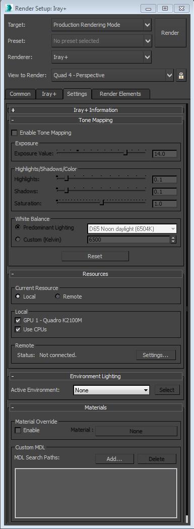
45 mrphotographic Exposure Control (3ds Max 2015) These settings are where everything comes together. The Exposure Settings will give control over how light will be viewed in the rendering in the exact same way as Exposure Settings for a camera would control light in a photograph. Shutter Speed, Aperture, and ISO, also known as the Exposure Triangle, are the three key settings to be used in this area. Though the option to combine all three into an Exposure Value (EV) is also available to simplify things. Additional settings for White Balance, and Tone-Mapping, are included to help refine the color and contrast in the rendering as well. mrphotographic Exposure Control Enable this under Environment Settings Use the EV scale for quick and easy settings Use the Camera Settings for more advance control Try to use real world exposure values for more realistic quality Set Highlight and Shadow settings to 0 Better to tone-map the render in post-production Make sure to set the White Balance to match your lighting IMAGE 4-11: An Exposure Value of 10 was used, with Highlights and Shadows set to 0.0. The White balance is set to 6500K due to the massive amount of daylight coming into the space. Page 45

46 IMAGE 4-12: This is the final output from the previous screenshot done in Iray! Page 46

47 Physical Camera (3ds Max 2016+) Autodesk teamed up with Chaos Group for a new feature in 3ds Max 2016 called the Physical Camera. This new camera type to 3ds Max completely mimics a real world DSLR camera, which goes to show how rendering is leaning more towards real-world photography. It is highly recommended to use the new Physical Camera, as it is now the default camera inside of 3ds Max. Also unlike the previous way, which is the mrexposurecontrol, the exposure settings will be unique to the camera. This will make it a lot easier to have different exposures for each camera in the scene, versus having to change the exposure settings over and over again for each camera. Due note that the Physical Camera Exposure Control is required to work with the Physical Camera. Do not use the mrexposurecontrol as the previous section mentions. The mrexpsourecontrol is only for 3ds Max 2015 and below. Physical Camera Features DSLR Camera Settings for each Physical Camera in the scene Film/Sensor settings that mimic real-world sensors Ability to change Shutter Speed to different types Recommended 1/seconds to mimic DSLR Enable Motion Blur for each Physical Camera in the scene Can use EV Scale or Specific ISO Value White Balance for each Physical Camera in the scene. Enable Depth Of Field which is controlled by Aperture, Film Width, and Focal Length Settings for Bokeh Effect Physical Camera Exposure Control enables global exposure with exposure for each individual camera in the scene. Under the Physical Camera Exposure Control, leave the setting User Per Camera Exposure Enabled. Use Exposure for Non-Physical Cameras to properly expose the Perspective and Orthographic views. This value is based on an EV Scale. Page 47


48 IMAGE 4-13: These are the settings for the new Physical Camera and Physical Camera Exposure Control. Individual settings will be based on the scene file. Real-World Camera Settings If the settings on a DSLR are uncommon to those working in the project, the following is a breakdown of the key settings that will affect the exposure of the renderings with the Physical Camera, and the mrphotographic Exposure Control. Aperture (f-stop) This setting will control Depth Of Field (DOF) in the camera. Usually f/8.0 f/11.0 is the sweet spot for most cameras, and is the ideal setting for shooting Architecture and Landscapes. This is due to how sharp the images come out, and results in very little DOF Decreasing the Aperture will increase the brightness, and increase the DOF effect Increasing the Aperture will decrease the brightness, and decrease the DOF effect Depth of Field needs to be enabled to take effect Page 48
49 Shutter Speed (1/seconds) This setting will control Motion Blur in the camera. The Shutter Speed will determine how fast the shutter of the camera closes. The higher this setting, the faster the shutter will shut. This results in freezing objects in motion, and will also decrease the brightness of the image Lowering the Shutter Speed will allow objects in motion to become blurry, and will increase the brightness of the image. Motion Blur needs to be enabled to take effect. ISO (Film Speed) This setting controls how much light hits the sensor in the camera. In the Real World, this would also control how much noise would be visible in the photograph. Decreasing the ISO value will darken the image, but create less noise in the photograph. Increasing the ISO value will brighten the image, but create more noise in the photograph. Note: Since the renderings are completely digital, the ISO setting will not create any noise in the rendering. However, it is recommended to add some noise back in Post Production to help mimic the effect. This will help the renderings look more like a photograph when it is finished. Exposure Value (EV) This is a value that combines the Exposure Triangle of Aperture (F-Stop), Shutter Speed, and ISO into one single value. All the various combinations will always yield the same level of exposure for the set Exposure Value. This can be a quick way to set the Exposure for the scene, especially if Depth of Field and Motion Blur are not required. The following settings are recommendations for certain scenarios. They are good starting points for reference, and the settings may need to be adjusted based on other variables in the project. These also assume real-world values are being used for the lighting in the project. Unrealistic values will result in these values being in-accurate. Daylight Settings Full Sunlight EV Hazy Sunlight EV 12 Cloudy Bright EV 12 Overcast EV 11 Open Shade with Clear Sunlight EV Interior Lighting Galleries EV 7-10 Office and Work Areas EV 6-8 Home Interiors EV 5-7 Page 49

50 White Balance This value is based off of the Kelvin Temperature Scale, and will determine what color value will be considered white by the camera. For instance, if the temperature of a light is 5000k, and the White Balance is set to 5000k, the light will appear white in the rendering. The higher the number, which results in a cool temperature, the warmer the rendering will look. The lower the number, which results in a warm temperature, the cooler the rendering will look. A value of 6500K is perfect for exterior daytime renderings. A value of K is a good starting point for interior renderings. This is a chart to help as a starting point with setting the White Balance. Color Temperature 6500K 5500K 6500K 5000K 4000K 5000K 3000K 4000K Light Source Daytime / Cloudy Daytime Camera Flash or LED Fluorescent Light Sunrise / Sunset K Incandescent Lighting K Tungsten Bulbs Image Control These settings will apply tone-mapping adjustments to the rendering, and can be found under the Physical Camera Exposure Control That will help with the contrast of the Highlights and the Shadows of the rendering. Leave these settings at default. It will give really good results from the start. Set Highlights and Shadows to 0 to remove any tone-mapping. Leave Mid-tones set to 1.0. Doing this will allow Tone Mapping to be applied in Post Production. Save the output in 32-bit EXR for best Dynamic Range. IMAGE 14: These renderings illustrate the differences in the Image Control. The center rendering is with the default settings. The left rendering is completely set to 0, and the right is set to 1.0. Page 50


51 Aperture (F-Stop) Examples: IMAGE 4-15: These renderings show the differences that the Aperture can make on a rendering. The first set just shows the difference in exposure, and the second set shows the difference in the Depth of Field effect when it is enabled. Note how the other settings have to adjust to keep the exposure the same during the Depth of Field effect. Page 51

52 Shutter Speed Examples: IMAGE 4-16: This set of renderings show the differences in how the shutter speed effects the renderings. The second set of renderings illustrates the effect of Motion Blur on moving objects. Note that the chair has been animated to move left to right in these renderings. Also note the differences in the F-Stop and ISO settings to keep the exposure the same. Page 52


53 ISO Examples: IMAGE 4-17: These renderings show the effect ISO can have on the exposure of a rendering. White Balance Examples: IMAGE 4-18: These renderings show the difference White Balance can have on the rendering. Note that the lights are set to 4500K, this is why the rendering with a White Balance of 4500K appears to have White light. Page 53


54 Exposure Value Examples: IMAGE 4-19: These renderings show how the Exposure Value effects an exterior Daytime scene. IMAGE 4-20: These renderings show how the Exposure Value effects and Interior Scene, with some Daylight entering the space through windows. Page 54

55 Chapter 5: NVIDIA Iray Settings The settings for Iray are pretty straight forward, and was designed this way on purpose by NVIDIA. Since Iray uses a direct approach to calculating everything in the render, there are no settings for quality other than telling Iray how long it should render. The rest of the settings are there to enable a few other effects such as Caustics, Displacement, and Motion Blur. The Depth of Field effect can be enabled on the 3ds Max camera itself. Enable Iray in both Production and Active Shade Setting Rendering Calculations: Time How long to render (Best to control time) Iterations How many calculations (Best for consistent quality) Unlimited Go until I say stop. (Best in Active Shade) Set Hardware Resources: Set the number of CPU Cores to render with Set which GPUs will do the rendering Disable GPU-0 (Windows) in ActiveShade for better performance Iray Production Mode Enable all CPUs and GPUs. LPEs are only available during Production Rendering. Best for rendering animations. Optimal Iterations for quality: Exterior: 3,000 5,000 Iterations Interior: 10,000 15,000+ Iterations IMAGE 5-1: These are all the settings for Iray! It s not that much! Page 55

56 Iray Active Shade When using Active Shade for rendering, it enables a majority of the interactive features if Iray. It is recommended to have at minimum two GPUs in your machine for optimal interactive performance, because the GPU dedicated to Windows should be disabled. This will allow 3ds Max to operate normally while rendering the project. Interactive Features: Material Changes Camera/Perspective Changes Exposure Changes White Balance Changes Non-interactive Features: Creating Lights Changing Light Intensity Moving Lights IMAGE 5-2: This is an example of what ActiveShade rendering with Iray can look like. You can do ActiveShade in its own window (Recommend) or you can turn a viewport into ActiveShade. Page 56

57 Chapter 6: Irradiance Mode (3ds Max 2016+) This is a major new feature to come to Iray in 3ds Max The Irradiance Mode is a Render Element that will allow you to view accurate light levels in your project. This Render Element will be extremely helpful when looking to see if the lighting design of the project is contributing enough to specification. When rendering this element, it will render the camera view with a white material that overrides all of the other materials in the project. Once the rendering is completed, the Irradiance Render Element will appear. This Render Element will appear as a Heat Map, which is a color coded rendering that relates to certain data. In this case, the data is displaying the value of light across the rendering in Lux. The color Dark Blue will correspond to the darkest part the rendering, and Bright Red will correspond with the brightest light in the rendering. A color graph will be included to show the relationship to the data and the colors. Enable Irradiance under the Render Elements This is found only in the Production Rendering Mode for Iray The main rendering will be completely white. The Irradiance will show up after the rendering fully completes. For best accuracy use the following IES files that are the correct specification to the lighting fixtures in the project. Use the 3ds Max Daylight System for the mrsun and mrsky. The following will reduce the accuracy of the Irradiance Render: Photometric Lights without IES files IBL (HDRI) used for the environment light and sunlight. IMAGE 6-1: This is the Irradiance Render Element output. This can only be enabled in Production Rendering. Page 57
58 Chapter 7: LPE and Post Production Light Path Expressions (LPE) can be considered as Render Elements on steroids. LPE s are actual equations that can pull out just about any kind of information that is specified into its own channel. For instance, if you want to just see what just the Environment Rays looks like, or if you wanted to see all the rays that hit a particular object, a simple equation would be able to pull that information for you when the render completes. This becomes extremely powerful in postproduction, because this allows the editing of those individual elements in Post. LPE s give extreme flexibility with the rendering, and in some cases the rendering might not need to be rerendered! All adjustments could be made in any Post Production application! Saving all of the renders and LPE s as EXR files is HIGHLY RECOMMENDED, and will give the most flexibility in Post due to EXRs being Full-Float 32-bit images. This means each pixel in the rendering is storing additional light and color data that can be adjusted. Normal 8-bit and 16-bit images are clamped to colors, and do not have any lighting information stored within the pixel. The EXR file format needs to be saved with a Gamma of 1.0, and by default 3ds Max 2016 is supposed to save EXR files with a Gamma of 1.0. If for some reason 3ds Max is not saving the EXR as 1.0, this can be set when saving the output in the Override Gamma Settings in the output window. LPE (Light Path Expressions) Mathematical Equations that can pull specific elements out of the buffer for compositing in post. Known as A Regular Expression Language (REGEX) More info on REGEX can be found here: You can write your own LPEs! Visit NVIDIA s Iray blog to follow and discuss more on LPEs Page 58

59 LPE Examples The following are examples of what LPEs look like. Some LPEs are preset as Render Elements inside of 3ds Max 2016, but there is the ability to add custom LPEs. NOTE: To save the LPE Render Elements, Iray must be set as the Primary Renderer. Also Iray must complete the rendering to generate the LPEs. If the rendering is canceled before it competes, the LPEs will not be generated. I want the whole beauty pass : Beauty Pass = L.*E Page 59
: Indirect")
60 I want to see only area light rays: Area Lights= La.*E I want only indirect illumination (two+ bounces): Indirect Illumination = L{2, }E Page 60


61 Note: The sunlight is considered Indirect Lighting with this LPE as it is bouncing through the glass, which is double sided. So the sunlight is already bouncing twice, or more, before entering the interior space. Inside of Photoshop, adding the Area Light Ray LPE and Indirect Illumination LPE together (In this case) will result in the Beauty Pass LPE. If the renders are in 32- bit use Linear Dodge blending mode. If the images are 16-bit or 8-bit use the Screen blending mode. Using 32-Bit will allow the ability to readjust the exposure for each element. Standard render elements, such as the Z-Depth, can be generated as well: Page 61
62 The Elements of LPEs LPEs consist of the following: A Light Source, an Event, and the Eye. A light source is defined by the type of light that will be considered for the LPE. An Event is the interaction of the light hitting an object and material in the render. And the Eye is pretty much the rendered view or camera. These three elements in the expression will drive the result into a new buffer channel for use in post-production. The grammar that drives the expression is pretty straight forward, and is natively designed to be abbreviated to make the expression simpler to specify. Eye E Eye/Camera/View Light Event L All Light Lp Point Light La Area Light Le Environment or Background Light <L handle > - Light Source defined by a handle. Light Interaction Events Each event of a path of light that interacts with an object in the scene is described by its three specifications: TYPE, MODE, and HANDLE(optional). It is contained by < >, and these three specifications for a Light Interaction Events look like: < t m h > Type (t) R - Reflection T - Transmission V - Volume Mode (m) D - Diffuse G - Glossy S Specular Handle (h) insert name here the inserted name refers to a grouping designated by a layer name in 3ds Max. The Event will be specified on this handle. If there is no handle, this specification can be ignored. (The are required around the handle name.) Symbols These are required to define, exclude, and abbreviate specifications for the LPE.. Defined as a Wild Card. This will accept any valid input in any Light Interaction Event position. * Defines any number of set Light Source Events. < > Page 62
63 [ ] ^ Defines the interaction between light and a material, which creates a Light Interaction Event Defines a Set within a Light Interaction Event for each specifier within the event. Excludes, or inverts, an element from a Light Interaction Event. Operands These Operands can be used to create sub-expressions. Both A and B represent the sub-expression, and m and n represent integer values for the expression, with m >= n. Parentheses (( )) can be used to group sub-expressions and change the order of evaluation. Operands will be evaluated in the following order: Quantifiers, Concatenation, and Alternatives. Sub-expressions in parentheses (( )) will be evaluated before anything else. Quantifiers? * + { } Concatenation A First Event or First LPE B Second Event or Second LPE Alternatives - Shows one or the other List of Operands AB Sets A first, then B. A B Sets A or B. A? Might set A, if A is present. It might not be. A* Sets any occurrences of A in sequential order, including zero times. A+ Sets any non-empty sequence of A s. A{n} Sets exactly n consecutive occurrences of A. A{n,m} Sets from n to m, inclusively, occurrences of A. A{n,} Sets n or more occurrences of A name: expression Sets a name for the expression to be referenced in another expression Page 63
64 $name References another named expression ^expression Creates the inverse of the expression. o Cannot be applied to sub-expressions RED Means not supported in Deconstructing LPE s After defining all of the elements that make up a LPE in the previous section, this will give a more comprehensive breakdown of each of the three parts that make up a LPE. The Light Event, the Light Interaction Event, and the Eye can have multiple combination of elements that can determine the output of the buffer that is trying to be rendered. And then there is the consolidation of the elements into each other to create more of a short-hand in writing the LPE. The ability to consolidate elements makes it easier to write LPEs, as they become shorter in the end. Light Event A LPE must either start or end with a Light Event. This is essentially the ray that is being casted through the scene and will define what is rendered in the buffer. One could look as this as the start of the LPE, as a ray is shot into the scene from a designated light source, or sources, and ends up at the eye. For example, by starting the LPE with L, we are stating that we want to see rays from every light in the scene. If we wanted to see the rays from the environment light, we would use Le in place of L. The next character in the equation is usually a., which is the wild card for anything in the Light Event. If left blank, the LPE will assume the wild card is wanted. This is a prime example of the consolidations in the equation that LPEs take advantage of. By not placing a variable in the equation, it will assume that you want it in the equation. Only when something is declared specifically, will it be taken into consideration. The third part in the Light Event is for a Quantifier. Most equations use the *, which means to show all the events/interactions/bounces of the ray. So a LPE that reads L.* E states: Show every light hitting everything, with all Light Interaction Events present, and send it to the Eye. This is what the LPE for a Beauty Pass, or Final Render looks like. (We will cover Light Interaction Events next, but note that they are not in the LPE due to the consolidation of the equation. Not including the Light Interaction Event in the LPE assumes everything about the Light Interaction event is to show true. Which means to render everything from the Light Interaction Event into the buffer.) However adding in alternative Quantifiers will give different results. Page 64
65 A LPE that reads L.? E would show every Light Interaction Event from every light source, but only show the direct lighting with no bounce light. The? says Show A, if A is present, but it might not be. In this case with L, we are asking to see only the direct lighting if visible. This is because in the previous Beauty Pass LPE, the? was replaced with *. Since the? is present now, it will not show any additional events/interactions/bounces of the Light Source. That was the * symbols job. If indirect illumination is desired, the equation would read L.{2,} E. The {n,} in this equation defines N number of occurrences of A or more. So with this in the Light Event, we are looking at N number of bounces of every Light (L) or more. In this case we are looking at 2 or more bounces, which is what indirect lighting is considered to be. Le. {2,} E could be only the indirect lighting from the Environment Light (Le). Note: In an interior rendering, if sunlight is coming through glass, it will be considered Indirect Illumination as it is bouncing through the glass before entering the interior. The last part for Light Events is if a specific light, or group of lights, needs to be specifically called out. This can be done with a Handle. If we have a set of lights called wallwash (which is defined as the name of a layer in the Layer Manger), we would call this in the LPE as <L wallwash >.* E. This LPE would show everything that was interacting with the lights on the wallwash layer. Light Interaction Event The middle portion of the LPE will always be the Light Interaction Event, which in itself consists of three different parts and is designated by the < >. The three parts go in order of: TYPE, MODE, and HANDLE. This can also look like < t m h> in the LPE. TYPE will define the type of interaction event to show. MODE will define the look of the event. HANDLE is optional, as it defines any specific Object in the scene to specify the event to. (Just like HANDLE in the Light Event.) L.*<RS> E would display the highlights for every light, or the entire scene. The R TYPE shows reflected light, and the S would display specular. Together this equals Specular Reflections. L.* R E would display everything for reflections. This goes back to the consolidation feature of LPEs. The Light Interaction Event could be defined as <R..>, which states Reflections TYPE, Wild Card for MODE (so show everything), Wild Card for HANDLE (so apply to every object). But typing R over <R..> is easier. Page 65
66 Inside of Light Interaction Events, there is the possibility to define more than one TYPE, MODE, or HANDLE in the LPE. This can be achieved using the [ ], which will define a Set. will display what is known as Reflection Pass for all lights. However the set for MODE [GS] only defines Glossy and Specular, so no Diffuse (D) reflections will be shown in this LPE. A Wild Card. cannot be placed inside of a Set. Therefor since Diffuse (D) is not defined, the LPE assumes that Diffuse Reflections are not wanted. Note: Be careful when abbreviating a Light Interaction Event. Reading the event as <RS> and RS are two completely different equations. The first is looking for a specular reflection, the latter is looking at a Reflection Event followed by a Specular Event. The latter can be considered two different Lighting Interaction Events in this case. The < > are key in keeping the two in one event.) Note: HANDLES are only supported in 3ds Max 2016 and Iray for 3ds Max Note: In 3ds Max 2016, HANDLE is defined by the name of the Layer in the Layer Explorer. Any objects, or lights, included in the Layer will be effected in the LPE. Note: In Iray for 3ds Max, the HANDLE is defined by the name of the object or light. Eye Event This is the easiest event of the entire LPE. This is designated as E and should either be at the start, or end, of the expression. LPE s in Post Production One good use-case scenario for LPEs is with the need to change the color of an object without having to re-render the entire application. This example will show the process of setting up a rendering with LPEs so the Fabric Wrap Panels (FWP) and Chairs can change color in Photoshop! Page 66


67 FWP L.* fwp.*e Chairs Diffuse L.* <RD chairs >.*E Page 67


68 Chair - Glossy L.* <RG chairs >.*E Invert FWP and Chairs ^(L.* ( fwp chairs ).*E) Page 68

69 IMAGE 7-1: This is the way to blend all the LPEs together inside of Photoshop. Page 69

70 IMAGE 7-2: The combined LPE s above generate the Beauty Pass, and then can be altered for an infinite amount of color variations without ever having to re-render the image. This can be extremely helpful when studying color options for finishes, etc. Since the LPE s show all the rays that bounce per pass, the color adjustments will show up in the bounce lighting and reflections! Page 70

71 Chapter 8: Iray + In addition to the version of Iray that comes installed with 3ds Max, NVIDIA has developed a 3 rd Party Plug-in for 3ds Max, in partnership with LightWorks, called Iray for 3ds Max. This version of Iray is much like the version that comes with 3ds Max 2016, but has more advanced support and rendering features. Iray for 3ds Max Features Convert Iray from 3ds Max to Iray for 3ds Max with a few clicks through an included converting tool. o Iray for 3ds Max does not support shaders other than the Iray for 3ds Max shaders, so scenes will need to be converted. o Iray for 3ds Max does not fully support the 3ds Max 2016 Physical Camera at this time. Direct MDL Support o Import MDL through the Iray for 3ds Max Shader o Supports Measured Material MDLs Fully Interactive in Active Shade o Every change in the scene will be updated in Active Shade buffer Two Flavors o Iray for 3ds Max Used for Photorealism o Iray for 3ds Max Interactive Super-fast, but limits ray bouncing to achieve the speed. NVIDIA VCA Support Iray Server IMAGE 8-1: A rendering of the Gensler LA Office done with Iray for 3ds Max! Page 71

72 Page 72

73 IMAGE 8-2: These are the rendering settings for Iray for 3ds Max. They are just as straight forward as Iray in 3ds Max 2016! Page 73

74 NVIDIA VCA The NVIDIA VCA is a server contains 8 Quadro M6000s and can be linked together with other VCAs through InfiniBand technology. Iray for 3ds Max will allow a direct connection to the VCA, enabling users to have access more GPUs than their desktops could ever hold. When the VCAs are linked, the number of GPUs that are available to render with go up exponentially. 8 Quadro M6000s per VCA Linked VCAs through InfiniBand Direct Connection to VCA through Iray for 3ds Max Interface Can reduce rendering times drastically Iray Server In order to take advantage of more than just the GPUs in the main workstation used for rendering, NVIDIA has created Iray Server. This will allow Iray for 3ds Max to access CUDA enabled NVIDIA GPUs across the network in other machines. Iray Server has the ability to do typical offline batch rendering or handle interactive streaming via H.264 or image formats. Iray Server is supported through any NVIDIA Iray Plugin Products. This can be an ideal solution for when the primary rendering machine is a laptop, which cannot take advantage of the powerful desktop Quadro GPUs. Supports any version of NVIDA Iray Plugins Can run on either Windows or Linux machines Cache Management minimizes submission times Flexible queue management system Entire cluster can coordinate together for rapid image creation Custom scripting allowed when jobs are completed Streaming behaves identically to local interactive rendering IMAGE 8-3: This diagram shows how Iray Server works across a network. (Provided by NVIDIA). Page 74

75 Rendering Workflows between Revit, 3ds Max, and Iray Chapter 9: Other Rendering Engines One question I get ask a lot after this course is: Does this workflow work for XXXX Render Engine? And the answer is: Absolutely! There s just a catch. The catch is that everything we ve talked about in this document assumes you re staying in the Revit/3ds Max ecosystem, which mainly refers to Materials, Lights, and Cameras. All of these elements are easily understood between the two applications, which is party of the beauty of this workflow. But if a 3 rd Party Rendering Engine is introduced into the mix, that interoperability is broken. To put it simply, you re going to have to convert Materials, Lights, and Cameras into something that the 3 rd Party Rendering Engine can understand. Most Render Engines have their own Materials, Lights and Cameras to use. (Sometimes they will understand the Cameras inside of 3ds Max just fine, as that s a native aspect of the 3ds Max SDK.) Iray for 3ds Max, which we just covered, is a 3 rd Party Rendering Engine developed directly by NVIDIA and Lightworks. If one were to follow this workflow, they would need to swap all the Lights and Materials with Iray+ Lights and Materials. So using a 3 rd Party Rendering Engine adds and extra layer of work to the process. It isn t the end of the world however. There are plenty of tools and scripts out in the 3ds Max community to help with this process. 3ds Max 2017 Scene Converter This is Autodesk s answer to converting Max Files to different rendering engines, and upgrading legacy content, inside of 3ds Max. It s a UI that can combine MaxScripts into an easy way to template and load scene conversions to another Rendering Engine. Currently by default, it only supports conversion to the newly introduced ART (Autodesk Raytracer). This is the new Render Engine that has been introduced with 3ds Max 2017, and it too supports very specific materials, lights and maps. Image 9-1: The Scene Converter proves to be a very advance tool for converting scenes. It however still needs customization support from 3 rd parties for their own engines. Page 75

76 Rendering Workflows between Revit, 3ds Max, and Iray Physical Material (3ds Max 2017+) Recently introduced in 3ds Max 2017, the Physical Material is the spiritual successor to the Arch+Design Material. This new shader is Autodesk s first step into moving 3ds Max into a render-agnostic platform. This will allow 3 rd Party Engines to adopt standard features in 3ds Max into their own engine. The Physical Material, this will have the ability to give the user one single material to use across multiple rendering engines inside 3ds Max. Rendering Engines that currently support Scanline, Quicksliver, ART, V-Ray, and Mental Ray. Image 9-2: The Physical Material inside of 3ds Max 2017 Page 76

77 Rendering Workflows between Revit, 3ds Max, and Iray MaxScripts One of the most powerful features that has been inside of 3ds Max for the longest time is the MaxScript. This is a programming language that can automate, and create new tools, directly inside of 3ds Max. There are websites dedicated to the distribution of free, and paid for, scripts that members of the 3ds Max community have made. There are numerous scripts created to do just about anything you can think of. I highly recommend looking on for scripts that will help with the translation process. Image 9-3: The Physical Material inside of 3ds Max 2017 Page 77
AV Using Autodesk 3ds Max Design, Autodesk Revit, and iray to Render Compelling Photographic Scenes
 AV4672 - Using Autodesk 3ds Max Design, Autodesk Revit, and iray to Render Compelling Photographic Scenes Steven Schain Autodesk Certified Instructor AV4672 This virtual class introduces designers to the
Iray for Cinema 4D Release Version 2.0 New Features Improved MDL Material Browser Stacking of MDL Material Layers
 Iray for Cinema 4D Release Version 2.0 Version 2.0.15, Iray 2016.3 Copyright 2017 NVIDIA Corporation Improved MDL Material Browser The MDL Material Browser has been greatly enhanced to allow quick and
AR-media TUTORIALS IMPROVING REALISM AMBIENT OCCLUSION. (June, 2011)
") AR-media TUTORIALS IMPROVING REALISM AMBIENT OCCLUSION (June, 2011) Copyright Copyright 2008/2011 Inglobe Technologies S.r.l. All rights reserved. No part of this publication may be reproduced, transmitted,
AR-media TUTORIALS IMPROVING REALISM AMBIENT OCCLUSION (June, 2011) Copyright Copyright 2008/2011 Inglobe Technologies S.r.l. All rights reserved. No part of this publication may be reproduced, transmitted,
Three OPTIMIZING. Your System for Photoshop. Tuning for Performance
 Three OPTIMIZING Your System for Photoshop Tuning for Performance 72 Power, Speed & Automation with Adobe Photoshop This chapter goes beyond speeding up how you can work faster in Photoshop to how to make
Visualization Insider A Little Background Information
 Visualization Insider A Little Background Information Visualization Insider 2 Creating Backgrounds for 3D Scenes Backgrounds are a critical part of just about every type of 3D scene. Although they are
Mastering Autodesk 3ds Max 2013
 Mastering Autodesk 3ds Max 2013 Harper, J ISBN-13: 9781118129715 Table of Contents Introduction? xxi Chapter 1? Getting to Know Autodesk? 3ds Max? 2013??? 1 Introducing the New 3ds Max 2013 Features????
Learning Objectives Learn how to efficiently create stunning imagery and animations of your Inventor models
 AV11903 AV11903 - Easy-to-Use Techniques for Bringing Your Design Content to the Next Level with 3ds Max Jose Elizardo 3ds Max technical Specialist Autodesk Learning Objectives Learn how to efficiently
V-RAY 3.6 FOR RHINO KEY FEATURES. January 2018
 V-RAY 3.6 FOR RHINO KEY FEATURES January 2018 NEW FEATURES MORE POWERFUL GPU RENDERING Faster, more powerful GPU rendering adds support for on-demand mip-mapping, aerial perspective, displacement, subsurface
AMD Radeon ProRender plug-in for PTC Creo. User Guide
 AMD Radeon ProRender plug-in for PTC Creo User Guide This document is a user and setup guide on how to render photorealistic images in real-time and apply decals for PTC Creo. DISCLAIMER The information
Lighting Techniques 1
 STEP 1: open your Class-05 Max fi le _ main menu / Customize / Units Setup _ set Display Unit Scale as shown in Image 1 _ set Lighting Units to: American STEP 2: select Daylight.01 _ command panel / modify
Creative Efficiency Research: MODO 801 vs. Maya From CAD file to finished rendering: How MODO stacks up in a real-world workflow situation
 Creative Efficiency Research: vs. From CAD file to finished rendering: How MODO stacks up in a real-world workflow situation About this Benchmark Project This benchmark project was conducted to measure
Textures and UV Mapping in Blender
 Textures and UV Mapping in Blender Categories : Uncategorised Date : 21st November 2017 1 / 25 (See below for an introduction to UV maps and unwrapping) Jim s Notes regarding Blender objects, the UV Editor
Or select Reset button under the application button (3ds Max symbol top left of screen)
") 3ds Max Notes 1. Starting 3ds Max file Open 3ds Max If Welcome to 3ds Max menu appears then select New Empty Scene Or select Reset button under the application button (3ds Max symbol top left of screen)
3ds Max Notes 1. Starting 3ds Max file Open 3ds Max If Welcome to 3ds Max menu appears then select New Empty Scene Or select Reset button under the application button (3ds Max symbol top left of screen)
V-RAY 3.6 FOR SKETCHUP KEY FEATURES
 V-RAY 3.6 FOR SKETCHUP KEY FEATURES November 2017 NEW FEATURES VIEWPORT RENDERING POWERFUL GPU RENDERING With new Viewport rendering, you can easily select and render multiple regions at once, and quickly
ICDAS 3ds Max Design & 3ds Max
 ICDAS 3ds Max Design & 3ds Max 2016.0 2016.0 C:\ICDAS\MANUAL\3ds Max Design\ICDAS 3ds Max Design & 3ds Max 2016.0, 2 ICDAS 2015-06-01 2014-06-01 2013-06-01 Dear user Welcome to 3ds Max Design and 3ds Max.
Caustics - Mental Ray
 Caustics - Mental Ray (Working with real caustic generation) In this tutorial we are going to go over some advanced lighting techniques for creating realistic caustic effects. Caustics are the bent reflections
Radeon ProRender add-in for SOLIDWORKS. User Guide v1.1
 Radeon ProRender add-in for SOLIDWORKS User Guide v1.1 This document is a user and setup guide with tips and tricks on how to render photorealistic images in real-time, apply decals and create animations.
Chapter 4- Blender Render Engines
 Chapter 4- Render Engines What is a Render Engine? As you make your 3D models in, your goal will probably be to generate (render) an image or a movie as a final result. The software that determines how
(Note: Gray text needs verification) 3DS Max - Merge native MAX files (Same or earlier version). Must select from list.
 3DS Max - Merge native MAX files (Same or earlier version). Must select from list.") Importing (Note: Gray text needs verification) 3DS Max - Merge native MAX files (Same or earlier version). Must select from list. 1. Geometry All 3D object and 2D shapes merge as do associated modifiers.
Importing (Note: Gray text needs verification) 3DS Max - Merge native MAX files (Same or earlier version). Must select from list. 1. Geometry All 3D object and 2D shapes merge as do associated modifiers.
AMD Radeon ProRender add-in for SOLIDWORKS. User Guide
 AMD Radeon ProRender add-in for SOLIDWORKS User Guide This document is a user and setup guide with tips and tricks on how to render photorealistic images in real-time, apply decals and create animations.
Max scene used to generate the image from the second pdf in this tutorial.
 Tutorial covers creating vector drawings from a 3ds max scene and methods for compositing these drawings back into a rendering. Rendering set up is based of the lighting set up from the mental ray/skylight/mr
Rendering Engines - Specific tools may depend on "Rendering Engine"
 Week 5 3DS Max, Cameras, Lighting and Materials Rendering - Process of turning geometry into pixels Rendering Engines - Specific tools may depend on "Rendering Engine" 1. Internal (3DS MAX) ART (Autodesk
Import / Object modes: 5 Layers for organising your scene are available at the top of the screen.
 LUMION 1 VS LUMION 2 SCENES - In Lumion 2, the sky, clouds, fog, material settings, ambient shadows and reflections have been overhauled, so don't expect your Lumion 1 scenes to look identical when you
ZBrush To Softimage XSI 16-Bit Displacement Guide
 ZBrush To Softimage XSI 16-Bit Displacement Guide Greg Punchatz Senior Creative Director, Janimation November 10, 2005 2005 Pixologic, Inc. All rights reserved. Pixologic and the Pixologic logo, and ZBrush
04. 3d Graphics UI & 3ds Max + MR
 Design + Computing 04. 3d Graphics UI & 3ds Max + MR 9/26/2014 CAD & Graphics II HOM2027 Fall 2014 Every Friday 2:00 pm 6:00 pm Jin Kook Lee, PhD. 02-2220-2645 designit@hanyang.ac.kr Assistant Professor,
WORKFLOW OF EXPORTING REVIT MODELS TO UNITY
 WORKFLOW OF EXPORTING REVIT MODELS TO UNITY 2016 by Penn State CIC Research Group. All rights reserved May 26, 2014 NOTE: THIS WORKFLOW IS FOR USERS WHO USE REVIT 2016 AND ABOVE, AND 3DS MAX 2016 AND ABOVE.
Artlantis training for new users
 Artlantis training for new users page 2 This training program reviews the main features of Artlantis. You will learn about the various presentation types such as still images, ivisit 3D panoramas, VR objects
Fundamentals. Autodesk SDC. Better Textbooks. Lower Prices. Schroff Development Corporation. Supplemental Files
 Autodesk 3ds Max Design 2012 Fundamentals Supplemental Files SDC PUBLICATIONS Schroff Development Corporation Better Textbooks. Lower Prices. www.sdcpublications.com Tutorial files on enclosed CD Table
Ambient Occlusion Pass
 Ambient Occlusion Pass (Soft Shadows in the Nooks and Crannies to Replicate Photorealistic Lighting) In this tutorial we are going to go over some advanced lighting techniques for an Ambient Occlusion
Render Submission Checklist
 Render Submission Checklist This document is intended to be used to perform manual checks to a scene before submitting the package to a Render Farm or to a 3 rd party to render your images. We are trying
Scene Assembly CHAPTER 4
 CHAPTER 4 Scene Assembly Scene assembly in the 3ds Max production pipeline is the process of tracking and assembling your scene assets for the complete presentation. A typical production workflow usually
Troubleshooting Views
 . Table of Contents Troubleshooting Views... 4 Problems that can occur with views... 4 Process to troubleshoot view display problems... 4 Tips and Tricks for solving view problems... 9 Family creation
REPORT SPONSORED BY AMD PRODUCED BY
 SOLIDWORKS VISUALIZATION A guide to getting the most out of real time rendering with RealView and ray trace rendering with PhotoView 360 in SolidWorks TECHNICAL REPORT SPONSORED BY AMD FIREPROGRAPHICS.COM/SOLIDWORKS
Autodesk Fusion 360: Render. Overview
 Overview Rendering is the process of generating an image by combining geometry, camera, texture, lighting and shading (also called materials) information using a computer program. Before an image can be
COS 116 The Computational Universe Laboratory 10: Computer Graphics
 COS 116 The Computational Universe Laboratory 10: Computer Graphics As mentioned in lecture, computer graphics has four major parts: imaging, rendering, modeling, and animation. In this lab you will learn
Point based global illumination is now a standard tool for film quality renderers. Since it started out as a real time technique it is only natural
 1 Point based global illumination is now a standard tool for film quality renderers. Since it started out as a real time technique it is only natural to consider using it in video games too. 2 I hope that
03. 3ds Max Design & Mental Ray
 Design + Computing 03. 3ds Max Design & Mental Ray 9/23/2015 CAD & Graphics II HOM2027 Fall 2014 Every Wednesday 2:00 pm 5:50 pm Jin Kook Lee, PhD. 02-2220-2645 designit@hanyang.ac.kr Assistant Professor,
Corona Sky Corona Sun Corona Light Create Camera About
 Plugin menu Corona Sky creates Sky object with attached Corona Sky tag Corona Sun creates Corona Sun object Corona Light creates Corona Light object Create Camera creates Camera with attached Corona Camera
Introduction to 3D Concepts
 PART I Introduction to 3D Concepts Chapter 1 Scene... 3 Chapter 2 Rendering: OpenGL (OGL) and Adobe Ray Tracer (ART)...19 1 CHAPTER 1 Scene s0010 1.1. The 3D Scene p0010 A typical 3D scene has several
Architectural Visualization Workflow in Autodesk Building Design Suite 2013
 Architectural Visualization Workflow in Autodesk Building Design Suite 2013 Marvi Basha TU Graz Class Summary - What is Arch-Viz? - Revit vs. 3Ds Max - Workflow - Post Production Class Summary - What is
Readme: Autodesk Impression
 Seite 1 von 6 Readme: Autodesk Impression Thank you for your interest in Autodesk Impression. Impression converts precision drawings to eye-catching design illustrations by applying appearance styles that
Importing and Exporting FilesChapter1:
 Importing and Exporting FilesChapter1: Chapter 1 You can use Revit Architecture to import and export various file types, including AutoCAD and AutoCAD Architecture DWG files to use as design aids. You
Rendering and Presentation
 Bonus Chapter 4 Rendering and Presentation Well, here we are the chapter you ve probably been chomping at the bit to get into and for good reason. The output that you create from this chapter will make
CET Designer 9.5 Release Notes
 CET Designer 9.5 Release Notes November 19, 2018 Important Notices Starting from this release, CET Designer is only available in a 64-bit version. For computers with damaged graphics drivers or a graphics
CHAPTER 1 COPYRIGHTED MATERIAL. Finding Your Way in the Inventor Interface
 CHAPTER 1 Finding Your Way in the Inventor Interface COPYRIGHTED MATERIAL Understanding Inventor s interface behavior Opening existing files Creating new files Modifying the look and feel of Inventor Managing
Advanced Maya Texturing and Lighting
 Advanced Maya Texturing and Lighting Lanier, Lee ISBN-13: 9780470292730 Table of Contents Introduction. Chapter 1 Understanding Lighting, Color, and Composition. Understanding the Art of Lighting. Using
Let s Make a Front Panel using FrontCAD
 Let s Make a Front Panel using FrontCAD By Jim Patchell FrontCad is meant to be a simple, easy to use CAD program for creating front panel designs and artwork. It is a free, open source program, with the
AB Fine-Tune Your Autodesk Revit Models for Autodesk 3ds Max
 AB5115 - Fine-Tune Your Autodesk Revit Models for Autodesk 3ds Max Pierre-Felix Breton Product Designer Autodesk Media and Entertainment Class Audience Autodesk 3ds Max users and Revit users who want to
n&os=win32_64
 DV21566 The Next Step in Design Visualization Ben Bisares Autodesk Media & Entertainment Technical Specialist Description Learn how to harness the power of Live Design to bring your creations to life.
: CASE STUDY: USING MAYA AND MENTAL RAY FOR PHOTOREALISTIC INTERIOR LIGHTING
 2006-1795: CASE STUDY: USING MAYA AND MENTAL RAY FOR PHOTOREALISTIC INTERIOR LIGHTING Marty Fitzgerald, East Tennessee State University American Society for Engineering Education, 2006 Page 11.312.1 Case
Animation Basics. Learning Objectives
 Animation Basics Learning Objectives After completing this chapter, you will be able to: Work with the time slider Understand animation playback controls Understand animation and time controls Morph compound
System Configuration and 3D in Photoshop CS5
 CHAPTER 1 System Configuration and 3D in Photoshop CS5 The Adobe Photoshop application works closely with your computer s hardware profile to use its capabilities most efficiently. This smart relationship
WHAT S NEW IN V-RAY NEXT FOR SKETCHUP. February 2019
 WHAT S NEW IN V-RAY NEXT FOR SKETCHUP February 2019 PRODUCT DESCRIPTION V-Ray Next for SketchUp is more than just a rendering engine. Designed to fit right within your SketchUp workflow, V-Ray Next for
Photo-realism Fundamentals
 1-(800) 877-2745 www.ashlar-vellum.com Photo-realism Fundamentals Using Cobalt, Xenon, Argon Copyright 2008 Ashlar Incorporated. All rights reserved. Photo-realism Fundamentals Photo-realistic rendering
3ds Max certification prep
 3ds Max certification prep Study online at quizlet.com/_25oorz 1. 24 Frames per second 2. 25 Frames per second, Europe 3. 30 Frames per second, Americas and Japan 4. Absolute mode, off set mode 5. How
CGDD 4113 Final Review. Chapter 7: Maya Shading and Texturing
 CGDD 4113 Final Review Chapter 7: Maya Shading and Texturing Maya topics covered in this chapter include the following: Shader Types Shader Attributes Texturing the Axe Life, Love, Textures and Surfaces
What s New In Autodesk VIZ Eddie Perlberg
 December 2-5, 2003 MGM Grand Hotel Las Vegas Eddie Perlberg VI12-1 Autodesk Architectural Desktop 2004 also includes VIZ Render, its very own visualization tool. VIZ Render uses some of the same technology
COS 116 The Computational Universe Laboratory 10: Computer Graphics
 COS 116 The Computational Universe Laboratory 10: Computer Graphics As mentioned in lecture, computer graphics has four major parts: imaging, rendering, modeling, and animation. In this lab you will learn
Procedural PBR Material Creation using Substance Designer for Visualization
 DV15677 Procedural PBR Material Creation using Substance Designer for Visualization Gensler Learning Objectives Learn how to create some basic materials Learn how to get started in Substance Designer Learn
On the Web sun.com/aboutsun/comm_invest STAROFFICE 8 DRAW
 STAROFFICE 8 DRAW Graphics They say a picture is worth a thousand words. Pictures are often used along with our words for good reason. They help communicate our thoughts. They give extra information that
Autodesk Viz Render Illuminated Speaker; Charles Busa
 December 2-5, 2003 MGM Grand Hotel Las Vegas Autodesk Viz Render Illuminated Speaker; Charles Busa BD3-3 Autodesk Viz Render Illuminated This course is an introduction to the new Autodesk VIZ Render. Learn
Who has worked on a voxel engine before? Who wants to? My goal is to give the talk I wish I would have had before I started on our procedural engine.
 1 Who has worked on a voxel engine before? Who wants to? My goal is to give the talk I wish I would have had before I started on our procedural engine. Three parts to this talk. A lot of content, so I
Working with Huge Digital Prototypes: Autodesk Inventor Large-Assembly Best Practices
 : Autodesk Inventor Large-Assembly Best Practices Dan Miles INCAT MA215-5 This session will provide methodologies and best practices for working with large Autodesk Inventor assemblies. With the last few
Architecture Engineering Training courses : Course BIM Architecture Diploma Revit Architecture 3D Max Vasari Navis Works Photoshop For Architects
 Architecture Engineering Training courses : Course BIM Architecture Diploma Revit Architecture 3D Max Vasari Navis Works Photoshop For Architects BIM ARCHITECTURAL DIPLOMA ( Design and visualization ):
COMPUTER HARDWARE SOFTWARE. B1 ORIENTATION WORKSHOP Emily Wilson (M5)
") COMPUTER HARDWARE SOFTWARE B1 ORIENTATION WORKSHOP Emily Wilson (M5) etwilson@dal.ca COMPUTER HARDWARE THE BIG QUESTION: MAC OR PC? SHORT ANSWER... Whatever you feel most comfortable with LONG ANSWER...
COMPUTER HARDWARE SOFTWARE B1 ORIENTATION WORKSHOP Emily Wilson (M5) etwilson@dal.ca COMPUTER HARDWARE THE BIG QUESTION: MAC OR PC? SHORT ANSWER... Whatever you feel most comfortable with LONG ANSWER...
CET Designer 9.5 Release Notes
 CET Designer 9.5 Release Notes Important Notices Starting from this release, CET Designer is only available in a 64-bit version. For computers with damaged graphics drivers or a graphics unit that does
Advanced Maya e Texturing. and Lighting. Second Edition WILEY PUBLISHING, INC.
 Advanced Maya e Texturing and Lighting Second Edition Lee Lanier WILEY PUBLISHING, INC. Contents Introduction xvi Chapter 1 Understanding Lighting, Color, and Composition 1 Understanding the Art of Lighting
Pharos Designer 2. Copyright Pharos Architectural Controls (15/1/2015)
") Pharos Designer 2 Welcome Welcome to Pharos Designer 2. We are delighted to introduce you to an entirely new version of the Pharos Designer software that picks up where the venerable and much- loved version
Pharos Designer 2 Welcome Welcome to Pharos Designer 2. We are delighted to introduce you to an entirely new version of the Pharos Designer software that picks up where the venerable and much- loved version
ISSUE #4 / SPRING 2017
 REVIT PURE PRESENTS PAMPHLETS ISSUE #4 / SPRING 2017 CAD revitpure.com Copyright 2017 - BIM Pure productions WHAT IS THIS PAMPHLET? Revit Pure Pamphlets are published 4 times a year by email. Each edition
Autodesk 3ds Max Design 2013 Fundamentals
 Autodesk 3ds Max Design 2013 Fundamentals Supplemental Files SDC P U B L I C AT I O N S Schroff Development Corporation Better Textbooks. Lower Prices. www.sdcpublications.com Tutorial files on enclosed
Introduction to Shutter Speed in Digital Photography. Read more:
 Introduction to Shutter Speed in Digital Photography Read more: http://digital-photography-school.com/shutterspeed#ixzz26mrybgum What is Shutter Speed? shutter speed is the amount of time that the shutter
Autodesk Revit MEP 2013
 Autodesk Revit MEP 2013 This document was last updated on March 22th, 2012. The following are Known Issues with this release: Assemblies When an assembly view is rotated, the crop region does not rotate
What s new in Autodesk 3ds Max 2016
 What s new in Autodesk 3ds Max 2016 Cadline Community 3ds Max 2016 3ds Max and 3ds Max Design Are Coming Together United for this release. Design-only features are now in 3ds Max 2016. 3ds Max 2016 A Unified
V-RAY NEXT FOR 3DS MAX
 V-RAY NEXT FOR 3DS MAX May 2018 Dabarti Studio NEW FEATURES POWERFUL SCENE INTELLIGENCE V-Ray Scene Intelligence analyzes your scene to optimize rendering. You automatically get the best quality in less
--APOPHYSIS INSTALLATION AND BASIC USE TUTORIAL--
 --APOPHYSIS INSTALLATION AND BASIC USE TUTORIAL-- Table of Contents INSTALLATION... 3 SECTION ONE - INSTALLATION... 3 SIDE LESSON - INSTALLING PLUG-INS... 4 APOPHYSIS, THE BASICS... 6 THE TRANSFORM EDITOR...
Rock Tutorial: Creating A Rock Like Seen In Gears Of War With A Focus On Normal
 http://www.icantbelieveitsnothighpoly.com/tutorials_new.html To view finished product 360 degrees around Instructions // Download: Video (Rotation of Final Mesh)/// (Right click and save) This is an advanced
Rendering and Animation for Building Design with 3ds Max
 Rendering and Animation for Building Design with 3ds Max Matt Dillon Vice President, Technical Services Enceptia Join us on Twitter: #AU2014 Agenda Setting up a 3ds Max Scene Exposure Control, Cameras
A Basic Guide to Modeling Landscapes in Google SketchUp
 DYNASCAPE SOFTWARE INC. A Basic Guide to Modeling Landscapes in Google SketchUp A DS Sketch 3D User Guide Volume 2 This guide will take you through the steps of creating a 3D model of a landscape in Google
Autodesk Revit Building and 3ds Max : A One-Two Punch
 11/28/2005-8:00 am - 9:30 am Room:N. Hemispheres (Salon A2) (Dolphin) Walt Disney World Swan and Dolphin Resort Orlando, Florida Autodesk Revit Building and 3ds Max : A One-Two Punch Roger Cusson - L'Atelier
Who Turned the Lights Out? Lighting Analysis with Autodesk Revit MEP 2012 and Autodesk 3ds Max Design 2012
 Who Turned the Lights Out? Lighting Analysis with Autodesk Revit MEP 2012 and Autodesk 3ds Max Design 2012 Eric Bogenschutz BSA LifeStructures MP5719 In this class, we will discuss multiple different lighting
Shadow Casting in World Builder. A step to step tutorial on how to reach decent results on the creation of shadows
 Shadow Casting in World Builder A step to step tutorial on how to reach decent results on the creation of shadows Tutorial on shadow casting in World Builder 3.* Introduction Creating decent shadows in
GPU-ACCELERATED RENDERING THAT KEEPS UP WITH THE CREATIVE PROCESS
 GPU-ACCELERATED RENDERING THAT KEEPS UP WITH THE CREATIVE PROCESS Nike USA Inc. NABD / Aixsponza Aixsponza renders larger models faster than ever thanks to the power of NVIDIA Quadro GP100 GPUs. BRINGING
RhinoCAM 2018 MILL Quick Start Guide. MecSoft Corporation
 2 Table of Contents About this Guide 4 1 Useful... Tips 4 2 About... the MILL Module 4 3 Using this... Guide 5 Getting Ready 6 1 Running... RhinoCAM 2018 6 2 About... the RhinoCAM Display 6 3 Launch...
10 Tips & Tricks for Creating Great Images Snagit 11
 10 Tips & Tricks for Creating Great Images Snagit 11 2013 TechSmith Corporation. All rights reserved. 10 Tips and Tricks for Creating Great Images This PDF guide contains some of the tips and tricks the
Because After all These Years I Still Don t Get it!
 BILT North America 2017 Westin Harbour Castle Toronto August 3-5 Session 3.2 Shared Coordinates: Because After all These Years I Still Don t Get it! Class Description In an effort to reveal the system
Topic 4 - Introduction to Metering on a DSLR
 Getting more from your Camera Topic 4 - Introduction to Metering on a DSLR Learning Outcomes In this lesson, we will look at another important feature on a DSLR camera called Metering Mode. By the end
Radeon ProRender add-in for SOLIDWORKS. User Guide v2.3
 Radeon ProRender add-in for SOLIDWORKS User Guide v2.3 This document is a user and setup guide with tips and tricks on how to render photorealistic images in real-time, apply decals and create animations.
2-3. What is Unity? 4-5. Asset Store. Lighting & Rendering Performance. Scripting. Efficient Workflow Mecanim. Pathfinding.
 What is Unity? Asset Store Lighting & Rendering Performance Scripting Efficient Workflow Mecanim Pathfinding Effects Union 2-3 4-5 6-7 8-9 10 11 12-13 14 15 16-17 What is Unity? Over 1,000,000 people use
Known Issues Autodesk Revit Building 9.1
 AUTODESK REVIT BUILDING 9.1 & 9 Known Issues Autodesk Revit Building 9.1 Windows 2000 Operating System If you are installing Revit Building 9.1 on a computer running Windows 2000, you must first run the
How to correctly utilize a linear workflow in 3ds Max, Various Renderers and Various Compositing Applications
 How to correctly utilize a linear workflow in 3ds Max, Various Renderers and Various Compositing Applications I have seen quite a lot of confusion surround Linear Workflow and 3ds Max. This is understandable,
Advanced Distant Light for DAZ Studio
 Contents Advanced Distant Light for DAZ Studio Introduction Important Concepts Quick Start Quick Tips Parameter Settings Light Group Shadow Group Lighting Control Group Known Issues Introduction The Advanced
Key Features and Benefits
 Autodesk Entertainment Creation Suites 2013 Key Features and Benefits Overview The Autodesk Entertainment Creation Suites 2013 provide an affordable end-to-end creative toolset used by leading artists
Game Development for
 Game Development for Who am I? Harry Krueger Senior Programmer at Housemarque Games Lead Programmer on Resogun Presentation Flow Intro to Housemarque and Resogun Housemarque Engine and Tools Platform-specific
Turn your movie file into the homework folder on the server called Lights, Camera, Action.
 CS32 W11 Homework 3: Due MONDAY, APRIL 18 Now let s put the ball in a world of your making and have some fun. Create a simple AND WE MEAN SIMPLE environment for one of your ball bounces. You will assign
3D ENGINE/DEVELOPER TOOLS ANALYSIS
 3D ENGINE/DEVELOPER TOOLS ANALYSIS SETH DAVIS MING TANG X3D X3D is a royalty-free open standards file format and run-time architecture to represent and communicate 3D scenes and objects using XML. It is
,
 [Class Room Online Training] Weekdays:- 2hrs / 3 days Fastrack:- 1½hrs / Day Weekend:- 2½ hrs (Sat & Sun) An ISO 9001:2015 Institute ADMEC Multimedia Institute www.admecindia.co.in 9911782350, 9811818122
Here s the general problem we want to solve efficiently: Given a light and a set of pixels in view space, resolve occlusion between each pixel and
 1 Here s the general problem we want to solve efficiently: Given a light and a set of pixels in view space, resolve occlusion between each pixel and the light. 2 To visualize this problem, consider the
Working with PDF s. To open a recent file on the Start screen, double click on the file name.
 Working with PDF s Acrobat DC Start Screen (Home Tab) When Acrobat opens, the Acrobat Start screen (Home Tab) populates displaying a list of recently opened files. The search feature on the top of the
AECOsim Building Designer Quick Start Guide
 AECOsim Building Designer Quick Start Guide Chapter A17 Rendering 2012 Bentley Systems, Incorporated www.bentley.com/aecosim Table of Contents Rendering...3 The Camera... 3 Materials... 5 Material Palettes...
THEA RENDER ADAPTIVE BSD ENGINE
 THEA RENDER ADAPTIVE BSD ENGINE ADAPTIVE (BSD) ENGINE Adaptive (BSD) is the name of the biased engine inside Thea Render. This engine is a biased one (this is why we use the abbreviation "BSD") as it uses