Radar Coherent Backscatter!
|
|
|
- Elaine Curtis
- 6 years ago
- Views:
Transcription

1 Radar Coherent Backscatter! Pixels in a radar image are a complex phasor representation of the coherent backscatter from the resolution element on the ground and the propagation phase delay!


2 Interferometric Phase Characteristics! Pixels in two radar images observed from nearby vantage points have nearly the same complex phasor representation of the coherent backscatter from a resolution element on the ground but a different propagation phase delay!
3 Correlation Theory! SIGNALS DECORRELATE DUE TO!! Thermal and Processor Noise!! Differential Geometric and Volumetric Scattering!! Rotation of Viewing Geometry!! Random Motions Over Time! DECORRELATION OBSERVED AS PHASE STANDARD DEVIATION!! Affects height and displacement accuracy and ability to unwrap phase!! Can define an effective SNR as thermal SNR degraded by other decorrelation effects!
4 Correlation Definition! For signals s 1 and s 2 observed at interferometer apertures 1 and 2, the correlation! is given by * s 1 s 2! " * * s 1 s 1 s 2 s 2 Deterministic signals" or combinations have " perfect correlation" s 2! 2! 1 s 1 Signals with random" components have " imperfect correlation"! 2i s 2i s 1i! 1i " = s 1 ei! 1 s 2 e #i! 2 s 1 2 s2 2 = 1 " = s 1i e i! 1i s 2i e #i!2i 2 2 s 1i s 2i i i i $ 1
5 Expectation Estimator! Expectation over the ensemble of realizations and cannot! be calculated from a specific realization, that is, the observations! s and. In general, an estimator derived from the image data! 1 s 2 must be devised.! The maximum likelihood estimator (MLE) of the interferometric phase! difference between images forming an interferogram that have homo-! geneous backscatter and constant phase difference is!!^ N,M " l.m = arg s 1l,m s 2l,m * where l and m are image indices relative to some reference location and the sum is computed over a N x M box. N and M are known as the number of looks in their respective image dimensions.! s 1i s 2i
6 Correlation Estimator! The standard estimator of the interferometric correlation between! images forming an interferogram that have homogeneous backscatter! and constant phase difference is!!^ = N, M N, M " l. m s s * 1 l,m 2l,m s s * " 1 s l, m 1l, m " s 2 l,m 2l,m l.m This estimator is biased. As an example, consider N = 1, M = 1. Then! N,M l.m *!^ = s s * 1 x, y 2 x, y s s * 1 s s x, y 1x,y 2 x, y 2x, y* = 1 where x and y are the coordinates of a particular image pixel. Other! biases arise when backscatter homogeneity and phase constancy are! violated.!
7 Correlation Estimator Characteristics! A general set of curves of reveals the nature of the estimator bias! when backscatter is homogeneous and phase is constant.!
8 !! Relationship of Phase Noise and Decorrelation! Increased decorrelation is associated with an increase in the interferometric phase noise variance! If averaging N > 4 samples, the phase standard deviation approaches the Cramer-Rao bound on the phase estimator:!! " = 1 2N 1# $ 2 $ Phase noise contributes! to height errors in inter-! ferometry as demonstrated! in the sensitivity equations!
9 Thermal Noise Decorrelation! Radar receiver electronics will add thermally generated noise to! the image observations.! s 1 ' = A b e j! b e " j 4# $ % 1 + n 1 ; s 2 ' = A b e j! b e " j 4# $ % 2 + n 2 The added noise contributes randomly to the interferometric phase! from pixel to pixel, causing thermal noise decorrelation. Assuming! ' ' uncorrelated noise, the correlation between s 1 and s 2 is! ( s 1 + n 1 )( s 2 + n 2 ) *! = ( s 1 + n 1 )( s 1 + n 1 ) * ( s 2 + n 2 )( s 2 + n 2 ) * = s 1 s 2 s 2 2 ( 1 + n 1 ) s n 2 ( ) = P 1 P 2 P 1 + N 1 P 21 + N 2 = N 1 / P N 2 / P 2
10 Thermal Noise Decorrelation! The correlation is related in a simple way to the reciprocal of the! Signal-to-Noise Ratio (SNR). For observations with identical! backscatter and equal noise power,!! = Decorrelation is defined as! 1 1+ N / P = SNR -1! = 1" # The decorrelation due to thermal noise can vary greatly in a scene,! not from thermal noise variations, but from variations in backscatter! brightness. Extreme cases are:!!radar shadow, where no signal is returns; correlation is zero.!!bright specular target, where signal dominates return; correlation is 1!
11 SNR from the Radar Equation! b! $% b! b! Commandable Radar Parameters! "! = pulse width (affects swath width and SNR)! # start = start of data collection window (affects starting look angle)! DWP = length of data collection window (affects swath width)! B = chirp bandwidth (affects range resolution)! h p!! l! N = kt eff B n where T eff = Effective Receiver Temperature B n = System Noise Bandwidth! i! &g! SNR = P t G t G r! 2 L t L r kt eff B n 4" & c$ ( ) 3 # 4 ( ' 2sin (% i ) ) + #% eff ( az ), o * g swath! P sys - lumped effect of transmit gain and various losses!
12 Baseline Decorrelation! Pixels in two radar images observed from nearby vantage points have nearly the same complex phasor representation of the coherent backscatter from a resolution element on the ground!
13 Baseline Decorrelation: Resolution Cell! Interferometric geometry for a horizontal baseline in the cross-track plane" A 1! B A 2! #%! 1%! 2% y sin! 1% y sin! 2% y! Origin of resolution cell"
14 Baseline Correlation Formulation! Consider signals from the two antennas displaced in angle:" Cross-correlation yields:" A 1! B! A 2! #%! 1%! 2% plus noise cross-products" y sin! 1% y! y sin! 2% &# y! f(x,y) = the surface reflectivity function" W(x,y) = the imaging point spread function"
15 Surface Assumption for Correlation Formulation! If the surface is modeled as uniformly distributed, uncorrelated scattering centers, that is: " where is the mean backscatter cross section per unit area" from the surface" Under this assumption, the correlation expression reduces to: " The shape of the correlation function as a function of angle is the Fourier Transform of the Image Point Spread Function"
16 Form of Baseline Correlation Function! If W(x,y) is assumed to be a sinc function, then the integral can be done in closed form (for ping-pong mode, p=2)" A 1! B A 2! #% For B>>#, % &! ' / #% &!% This function goes to zero at the" critical baseline! B ",crit = #$ p%$ " p=1, 2!
17 The Pixel Antenna View of " Baseline Decorrelation! Radar" Sensor" v!!% #% Each resolution element can be con-! sidered a radiating antenna with beam-! width of "# "$%, which depends on the! range and local angle of incidence.! Image Pixel/" Resolution Element" (p=2 in this case)! When the two apertures of the! interferometer are within this! beamwidth, coherence is main-! tained. Beyond this critical! baseline separation, there is no! coherence for distributed targets! Image Pixel/" Resolution Element"!%


18 Overcoming Baseline Decorrelation! &#% Effective! Projected Resolution! Distributed targets correlate over a narrow range of baselines! Urban Corner Reflectors" &#% JPL Corner Reflector" Effective Range Resolution! Corner Reflector Pixels dominated by single scatterers generally behave though imaged at much finer resolution!
19 Critical Baseline! The critical baseline is the aperture separation perpendicular to the look direction at which the interferometric correlation becomes zero.! B crit = "#$ #"% = &"tan$ p! n#" Interferometers with longer wavelengths and finer resolution are less sensitive to baseline decorrelation. When the critical baseline is reached, the interferometric phase varies as! "# crit "$ = "# crit "% "% "$ = 2n& 2p!" ' B crit 1 $tan% = 2& ($ p=1,2! The relative phase of scatterers across a resolution element! changes by a full cycle, leading to destructive coherent summation!
20 Rotational Decorrelation! Rotation of scatterers in a resolution element can be thought of as! observing from a slightly different azimuthal vantage point. As with! baseline decorrelation, the change in differential path delay from! individual scatterers to the reference plane produces rotational! decorrelation.!
21 Rotational Correlation Formulation! Cross-correlation for this case is:" plus noise cross-products"
22 Form of Rotational Correlation Function! A similar Fourier Transform relation as found in the baseline decorrelation formulation exists" p! p=1,2! where R x is the azimuth resolution" and B ( is the distance along track corresponding to the rotation angle of the look vector " This function goes to zero at the" critical rotational baseline! p!
23 Scatterer Motion! Motion of scatterers within the resolution cell from one observation! to the next will lead to randomly different coherent backscatter! phase from one image to another, i.e. temporal decorrelation.! Radar Sensor v A b (t 1 )e j" b (t 1 ) Initial Observation! " A e j b b Image Pixel/ Resolution Element A b (t 2 )e j" b (t 2 ) Image Pixel/ Resolution Element Some time later Propagation Phase Delay " = # j 4$ %!
24 Motion Correlation Formulation! Assume the scatterers move in the cross-track and vertical directions by random displacements from one observation to the next by )y and )z. The cross-correlation for this case is:" If the motions are independent and unrelated to position" plus noise cross-products" where p y and p z are the probability distributions of the scatterer locations"
25 Form of Motion Correlation Function! The Fourier Transform relation can be evaluated if Gaussian probability distributions for the motions are assumed" where * y,z is the standard deviation of the scatterer displacements crosstrack and vertically" Note correlation goes to 50% at about 1/4 wavelength displacements"

!")
26 Repeat-pass Interferometry and Coherent Change Detection L-Band low frequency improves correlation in vegetated areas Most radars do well in areas of sparse vegetation! But maintaining correlation in dense vegetation requires longer wavelengths! Correlation! Loss of correlation is due to:!! volume of vegetation!! movement of vegetation!! dielectric change (moisture)! P- L- C- X-! Frequency band! Effective phase center! VHF! UHF! P-band! L-band! C-band! X-band!


27 Coherent Change Detection SIR-C L and C-band Interferometry 6 month time separated observations to form interferograms Simultaneous C and L band InSAR experiments have shown good correlation at L-band


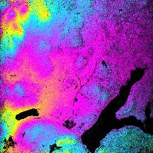
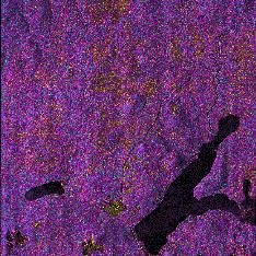
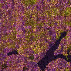
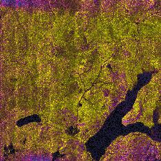
28 AIRSAR Coherent Change Detection Interferograms! C-band! L-band! P-band! Correlation! Airborne InSAR experiments have shown good correlation at L-band


29 A Correlation Test:" What were the interferometric " observation conditions?!
30 Correlation in Practical Systems!! For Single-Pass Two-Aperture Interferometer Systems"! System noise and baseline/volumetric decorrelation are particularly relevant"! Proper design of system can control "! noise, by increasing SNR and minimizing shadow"! baseline decorrelation, by choosing proper wavelength and geometry"! Volumetric decorrelation can be inferred and used as a diagnostic of the vertical distribution of scatterers"! For Multi-Pass Single-Aperture Interferometer Systems"! All decorrelation effects may occur"! Time series analysis and some assumptions may be useful in distinguishing decorrelation contributors"
31 Correlation Discrimination! repeat-pass!! =! SNR! B! V! t! " noise! baseline! volumetric! single-pass!! SNR rotational! temporal! For a calibrated interferometer, can be calculated for each pixel.! For single-pass systems,! t = 1 and! " is usually nearly unity.! The baseline decorrelation can be computed from the known geometry,! leaving the volumetric correlation, which can used as a diagnostic of! surface scatterers.! For calibrated repeat-pass systems with no rotational decorrelation,! the product! V! t is separable only if! t " 0 and! V estimates! from several baselines are compared.!
32 Interferometric Error Sources!!! Interferometric Decorrelation! In addition to the decorrelation contributions, several other sources of error exist in interferometry. These include!!! Layover and shadow in radar imagery from slant range geometry!!! Multiple scattering within and among resolution cells!!! Range and Azimuth sidelobes due to bandwidth/resolution constraints!!! Range and azimuth ambiguities due to design constraints!!! Multipath and channel cross-talk noise as low-level interference!!! Phase unwrapping errors!!! Calibration errors!!! Propagation delay errors from atmosphere and ionosphere!

33 Hawaii SIR-C One Day Repeat Pass Data Showing Tropospheric Distortion! 0 Relative Phase 2+% DAYS 7-8 TWO-PASS DAYS 7-10 TWO-PASS DAYS THREE-PASS!

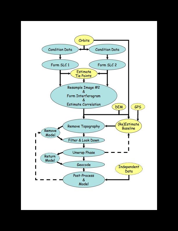
34 The ROI_PAC Algorithmic Flow! 34!
35 Scene Matching and Coregistration! Cross-correlate images by expedient method" Tie-points by eye Amplitude correlation Fringe visibility Amplitude difference REFERENCE IMAGE MIS-REGISTERED IMAGE a!! Fit a 2-D function (polynomial) to ("!,"a) offset field
36 !!!! Automatic Scene Matching! Find overlap region and sample points at specified spacing in along track and cross track direction." Typical window sizes are 64x64 pixels for image data and 64x64 or 128x128 pixels for height data." Uses a modified Frankot's method for rejecting bad matches and to provide an estimate of the match covariance matrix." Cross correlation uses a normalized mean correlation function, mean of search window is calculated over the region in common with the reference window." Mean of reference! is constant! Reference Window d! Search Window! Mean of search! varies with position!
37 ! Correlation is computed in the spatial domain using a normalized cross correlation algorithm. "! Let I 1 (! be the image values at a point! x ) x in the reference window in the first data set, I 1, the mean of the intensities in that window."! Let I 2 ( x! + d! ) be the image value at point in the search window of the second data set, and I 2 (!! x + d! d ) the mean of the intensities in that window. "! Match Correlation Estimate! Viewing each image as a vector in an n-dimensional vector space then the cross correlation is computed as" c( d! ) = I 1! I 1, I 2 ( d! )! I 2 ( d! ) I 1! I 1 I 2 ( d! )! I 2 ( d! ) = I 1! I 1, I 2 (! d )! I 2 ( d! ) " I1 " I2 (! where! and! I1 are the standard deviations of the image! I 2 ( d! ) intensities in data sets 1 and 2, respectively.! Space-domain correlation used for speed and because large! irregular data gaps are trouble free.! d )
38 Track 1 Interferogram Formation! Interferogram Independently Processed Single Look Complex Images Doppler spectra! matched during! processing! Cross- Multiply and Multilook Detected Imagery Track 2 Corregistration Offset Estimates Resample Complex Image 2-D Polynomial Fit From interferogram and! detected imagery, corr-! lation can be formed! properly at any resolution:! i.e. average of correlation! is not correlation of average!

39 Registration Implementation!!! In resampling single look complex image to register properly with the reference image, care must be taken in interpolation of complex data"! The azimuth spectrum of squinted SAR data is centered at the Doppler centroid frequency - a band-pass signal"! Simple interpolators, such as linear or quadratic interpolators, are low-pass filters and can destroy band-pass data characteristics" Band-pass interpolators or spectral methods preserve phase fidelity"
40 Interferogram Repeat Pass Interferometry" Back-end Processing! Remove Reference Fringes Unwrap Phase Performance Summary: L-band: good over most terrain C-band: poor over most terrain Replace Reference Fringes Detected Imagery Correlation File and Mask Geolocation Single-look Corregistration Offset Estimates Estimate Baseline Heights, etc. Amplitude DEM/Topo Correlation
41 2-Pass Differential Processing! Interferogram Remove Reference Fringes Unwrap Phase Detected Imagery Correlation File and Mask Geolocation Baseline Estimate DEM/Topo Simulate Interferogram Phase Range/Doppler -> Lat/Lon Mapping Displacements Amplitude Correlation
42 ! Phase Unwrapping! Elements of the phase unwrapping problem: From the measured, wrapped phase, unwrap the phase from some arbitrary starting location, then determine the proper ambiguity cycle." # "# # "# Actual phase! Wrapped (measured) phase!! = " 4# $ ( %1 " ) %2 & " 4# $!meas = mod (!,2# )! B ' ˆ n los # "#!unw = Typical unwrapped phase! k "(!meas) =! + 2#k where is an integer to return the absolute phase
43 Two-Dimensional Phase Unwrapping!!! Two dimensional phase field values below are in units of cycles" One-dimensional unwrapping criterion of half-cycle proximity is inconsistent in two dimensions " 0.0!0.0!0.3!0.0!0.0!0.3!0.0! !0.3!0.6!0.3!0.3!0.6!0.3! !0.0!0.9!0.6!0.6!0.9!0.0! !0.0!1.2!0.9!0.9!1.2!0.0! !0.0!1.2!0.9!0.9!1.2!0.0! !0.0!0.9!0.6!0.6!0.9!0.0! !0.3!0.6!0.3!0.3!0.6!0.3! !0.0!0.3!0.0!0.0!0.3!0.0! !0.0!0.3!0.0!0.0!0.3!0.0! !0.3!0.6!0.3!0.3!0.6!0.3! !0.0!-0.1!-0.4!-0.4!-0.1!0.0! !0.0!0.2!-0.1!-0.1!0.2!0.0! !0.0!0.2!0.9!-0.1!0.2!0.0! !0.0!-0.1!-0.4!-0.4!-0.1!0.0! !0.3!0.6!0.3!0.3!0.6!0.3! !0.0!0.3!0.0!0.0!0.3!0.0!0.0!! Residues, marked with + and -, define ambiguous boundaries.!
44 ! Residues in Phase Unwrapping! The wrapping operator delivers the true phase modulo 2 +, in the interval -+ < ( < +. "! The true phase gradient is conservative: "! "!# = 0!!! The wrapped gradient of the measured, wrapped phase, however, may not be conservative:"! " W{!# w } $ 0 When this function is non-conservative, its integration becomes path dependent." Residues occur at locations of high phase noise and/or phase shear such that the wrapped gradient of the measured, wrapped phase is no longer conservative." Wrapped gradient across True phase 0.3!0.6! 0.0! ! ! !0.9! Wrapped phase! 0.3!0.3!-0.4! -0.3!! 0.3!0.0!-0.1!! -0.1!0.0!0.2! 0.2!0.0! !! -0.3!0.0!-0.1! -0.1 Wrapped gradient down
45 !! Branch Cuts in Phase Unwrapping! Branch-cut algorithms (Goldstein, Zebker, and Werner 1986) seek to neutralize these regions of inconsistency by connecting residues of opposite solenoidal sense with cuts, across which integration may not take place. " Branch cut connections force path independence in the integration of the wrapped phase gradient."! If done properly, the integrated phase field will be correct. But which is correct? " 0.0!0.0!0.3!0.0!0.0!0.3!0.0! !0.3!0.6!0.3!0.3!0.6!0.3! !0.0!0.9!0.6!0.6!0.9!0.0! !0.0!1.2!0.9!0.9!1.2!0.0! !0.0!1.2!0.9!0.9!1.2!0.0! !0.0!0.9!0.6!0.6!0.9!0.0! !0.3!0.6!0.3!0.3!0.6!0.3! !0.0!0.3!0.0!0.0!0.3!0.0! !0.0!0.3!0.0!0.0!0.3!0.0! !0.3!0.6!0.3!0.3!0.6!0.3! !0.0!-0.1!-0.4!-0.4!-0.1!0.0! !0.0!0.2!-0.1!-0.1!0.2!0.0! !0.0!0.2!0.9!-0.1!0.2!0.0! !0.0!-0.1!-0.4!-0.4!-0.1!0.0! !0.3!0.6!0.3!0.3!0.6!0.3! !0.0!0.3!0.0!0.0!0.3!0.0!0.0
46 Illustration of Branch Cut Algorithm! Connect all simple" pairs" Expand search window" and connect where " possible" Could not connect" last residue with this " search window size" Initiate search from " every residue " encountered" Repeat all steps with " larger search window size"


47 Branch Cut Strategies!!!! The standard GZW algorithm is designed to connect residues into a neutral network into the shortest possible connection tree, i.e. to minimize the length of the individual branch cuts comprising a tree" This will not necessarily create the shortest possible tree, since GZW makes many unnecessary connections in its search for neutrality" Various criteria have been devised to place guiding centers (unsigned residues) along expected paths to facilitate the right choice in branch cut connection" Residues" Guiding Centers"
48 Guiding Center Criteria!! A number of criteria have been devised for selecting guiding centers, each more or less tailored to characteristics of SAR data:"! when phase slope exceeds threshold (implies layover)"! when derivative of phase slope exceeds threshold"! when radar brightness exceeds threshold (implies layover)"! when decorrelation estimator exceeds threshold (implies noise and/or layover"! Some guiding center selections help in some cases "! Difficult to assess performance in a quantitative way"
 phase\" Typical unwrapped phase\" \"# Ground control")
49 Absolute Phase Determination! Actual phase" # "# # "# # Wrapped (measured) phase" Typical unwrapped phase" "# Ground control reference points can be used to determine the absolute phase ambiguity"
50 Other Resources! M. Simons and P. Rosen, Interferometric Synthetic Aperture Radar Geodesy Treatise on Geophysics, Schubert, G. (ed.), Volume 3- Geodesy, Elsevier Press, pp , Rosen, P. A.; Hensley, S.; Joughin, I. R.; Li, F. K.; Madsen, S. N.; Rodriquez, E. & Goldstein, R. M. Synthetic Aperture Radar Interferometry Proc. IEEE, 2000, 88, Burgmann, R.; Rosen, P. & Fielding, E. Synthetic Aperture Radar Interferometry to measure Earth's surface topography and its deformation Ann.~Rev.~Earth Planet.~Sci., 2000, 28, Madsen, S. N. & Zebker, H. A. Synthetic Aperture Radar Interferometry: Principles and Applications Manual of Remote Sensing, Artech House, 1999, 3 Massonnet, D. & Feigl, K. L. Radar interferometry and its application to changes in the earth's surface Reviews of Geophysics, 1998, 36, Bamler, R. & Hartl, P. Synthetic Aperture Radar Interferometry Inverse Problems, 1998, 14, !
A Correlation Test: What were the interferometric observation conditions?
 A Correlation Test: What were the interferometric observation conditions? Correlation in Practical Systems For Single-Pass Two-Aperture Interferometer Systems System noise and baseline/volumetric decorrelation
Scene Matching on Imagery
 Scene Matching on Imagery There are a plethora of algorithms in existence for automatic scene matching, each with particular strengths and weaknesses SAR scenic matching for interferometry applications
Sentinel-1 Toolbox. Interferometry Tutorial Issued March 2015 Updated August Luis Veci
 Sentinel-1 Toolbox Interferometry Tutorial Issued March 2015 Updated August 2016 Luis Veci Copyright 2015 Array Systems Computing Inc. http://www.array.ca/ http://step.esa.int Interferometry Tutorial The
Interferometry Tutorial with RADARSAT-2 Issued March 2014 Last Update November 2017
 Sentinel-1 Toolbox with RADARSAT-2 Issued March 2014 Last Update November 2017 Luis Veci Copyright 2015 Array Systems Computing Inc. http://www.array.ca/ http://step.esa.int with RADARSAT-2 The goal of
Interferometric Synthetic-Aperture Radar (InSAR) Basics
 Basics") Interferometric Synthetic-Aperture Radar (InSAR) Basics 1 Outline SAR limitations Interferometry SAR interferometry (InSAR) Single-pass InSAR Multipass InSAR InSAR geometry InSAR processing steps Phase
Interferometric Synthetic-Aperture Radar (InSAR) Basics 1 Outline SAR limitations Interferometry SAR interferometry (InSAR) Single-pass InSAR Multipass InSAR InSAR geometry InSAR processing steps Phase
Repeat-pass SAR Interferometry Experiments with Gaofen-3: A Case Study of Ningbo Area
 Repeat-pass SAR Interferometry Experiments with Gaofen-3: A Case Study of Ningbo Area Tao Zhang, Xiaolei Lv, Bing Han, Bin Lei and Jun Hong Key Laboratory of Technology in Geo-spatial Information Processing
Sentinel-1 Toolbox. TOPS Interferometry Tutorial Issued May 2014
 Sentinel-1 Toolbox TOPS Interferometry Tutorial Issued May 2014 Copyright 2015 Array Systems Computing Inc. http://www.array.ca/ https://sentinel.esa.int/web/sentinel/toolboxes Interferometry Tutorial
PSI Precision, accuracy and validation aspects
 PSI Precision, accuracy and validation aspects Urs Wegmüller Charles Werner Gamma Remote Sensing AG, Gümligen, Switzerland, wegmuller@gamma-rs.ch Contents Aim is to obtain a deeper understanding of what
Memorandum. Clint Slatton Prof. Brian Evans Term project idea for Multidimensional Signal Processing (EE381k)
") Memorandum From: To: Subject: Date : Clint Slatton Prof. Brian Evans Term project idea for Multidimensional Signal Processing (EE381k) 16-Sep-98 Project title: Minimizing segmentation discontinuities in
Memorandum From: To: Subject: Date : Clint Slatton Prof. Brian Evans Term project idea for Multidimensional Signal Processing (EE381k) 16-Sep-98 Project title: Minimizing segmentation discontinuities in
Interferometric processing. Rüdiger Gens
 Rüdiger Gens Why InSAR processing? extracting three-dimensional information out of a radar image pair covering the same area digital elevation model change detection 2 Processing chain 3 Processing chain
Lateral Ground Movement Estimation from Space borne Radar by Differential Interferometry.
 Lateral Ground Movement Estimation from Space borne Radar by Differential Interferometry. Abstract S.Sircar 1, 2, C.Randell 1, D.Power 1, J.Youden 1, E.Gill 2 and P.Han 1 Remote Sensing Group C-CORE 1
GAMMA Interferometric Point Target Analysis Software (IPTA): Users Guide
: Users Guide") GAMMA Interferometric Point Target Analysis Software (IPTA): Users Guide Contents User Handbook Introduction IPTA overview Input data Point list generation SLC point data Differential interferogram point
GAMMA Interferometric Point Target Analysis Software (IPTA): Users Guide Contents User Handbook Introduction IPTA overview Input data Point list generation SLC point data Differential interferogram point
Individual Interferograms to Stacks!
 Individual Interferograms to Stacks! Piyush Agram! Jet Propulsion Laboratory!! Jun 29, 2015! @UNAVCO! Thanks to my colleagues from JPL, Caltech, Stanford University and from all over the world for providing
SAR Interferometry. Dr. Rudi Gens. Alaska SAR Facility
 SAR Interferometry Dr. Rudi Gens Alaska SAR Facility 2 Outline! Relevant terms! Geometry! What does InSAR do?! Why does InSAR work?! Processing chain " Data sets " Coregistration " Interferogram generation
Individual Interferograms to Stacks
 Individual Interferograms to Stacks Piyush Agram Jet Propulsion Laboratory Aug 1, 2016 @UNAVCO Thanks to my colleagues from JPL, Caltech, Stanford University and from all over the world for providing images
In addition, the image registration and geocoding functionality is also available as a separate GEO package.
 GAMMA Software information: GAMMA Software supports the entire processing from SAR raw data to products such as digital elevation models, displacement maps and landuse maps. The software is grouped into
The 2017 InSAR package also provides support for the generation of interferograms for: PALSAR-2, TanDEM-X
 Technical Specifications InSAR The Interferometric SAR (InSAR) package can be used to generate topographic products to characterize digital surface models (DSMs) or deformation products which identify
A STATISTICAL-COST APPROACH TO UNWRAPPING THE PHASE OF INSAR TIME SERIES
 A STATISTICAL-COST APPROACH TO UNWRAPPING THE PHASE OF INSAR TIME SERIES Andrew Hooper Delft Institute of Earth Observation and Space Systems, Delft University of Technology, Delft, Netherlands, Email:
Do It Yourself 8. Polarization Coherence Tomography (P.C.T) Training Course
 Training Course") Do It Yourself 8 Polarization Coherence Tomography (P.C.T) Training Course 1 Objectives To provide a self taught introduction to Polarization Coherence Tomography (PCT) processing techniques to enable
Do It Yourself 8 Polarization Coherence Tomography (P.C.T) Training Course 1 Objectives To provide a self taught introduction to Polarization Coherence Tomography (PCT) processing techniques to enable
RESOLUTION enhancement is achieved by combining two
 IEEE GEOSCIENCE AND REMOTE SENSING LETTERS, VOL. 3, NO. 1, JANUARY 2006 135 Range Resolution Improvement of Airborne SAR Images Stéphane Guillaso, Member, IEEE, Andreas Reigber, Member, IEEE, Laurent Ferro-Famil,
Coherence Based Polarimetric SAR Tomography
 I J C T A, 9(3), 2016, pp. 133-141 International Science Press Coherence Based Polarimetric SAR Tomography P. Saranya*, and K. Vani** Abstract: Synthetic Aperture Radar (SAR) three dimensional image provides
MULTI-TEMPORAL INTERFEROMETRIC POINT TARGET ANALYSIS
 MULTI-TEMPORAL INTERFEROMETRIC POINT TARGET ANALYSIS U. WEGMÜLLER, C. WERNER, T. STROZZI, AND A. WIESMANN Gamma Remote Sensing AG. Thunstrasse 130, CH-3074 Muri (BE), Switzerland wegmuller@gamma-rs.ch,
SAOCOM 1A INTERFEROMETRIC ERROR MODEL AND ANALYSIS
 SAOCOM A INTERFEROMETRIC ERROR MODEL AND ANALYSIS Pablo Andrés Euillades (), Leonardo Daniel Euillades (), Mario Azcueta (), Gustavo Sosa () () Instituto CEDIAC FI UNCuyo & CONICET, Centro Universitario,
Letter. Wide Band SAR Sub-Band Splitting and Inter-Band Coherence Measurements
 International Journal of Remote Sensing Vol. 00, No. 00, DD Month 200x, 1 8 Letter Wide Band SAR Sub-Band Splitting and Inter-Band Coherence Measurements D. DERAUW, A. ORBAN and Ch. BARBIER Centre Spatial
Airborne Differential SAR Interferometry: First Results at L-Band
 1516 IEEE TRANSACTIONS ON GEOSCIENCE AND REMOTE SENSING, VOL. 41, NO. 6, JUNE 2003 Airborne Differential SAR Interferometry: First Results at L-Band Andreas Reigber, Member, IEEE, and Rolf Scheiber Abstract
DINSAR: Differential SAR Interferometry
 DINSAR: Differential SAR Interferometry Fabio Rocca 1 SAR interferometric phase: ground motion contribution If a scatterer on the ground slightly changes its relative position in the time interval between
A SPECTRAL ANALYSIS OF SINGLE ANTENNA INTERFEROMETRY. Craig Stringham
 A SPECTRAL ANALYSIS OF SINGLE ANTENNA INTERFEROMETRY Craig Stringham Microwave Earth Remote Sensing Laboratory Brigham Young University 459 CB, Provo, UT 84602 March 18, 2013 ABSTRACT This paper analyzes
Filtering, unwrapping, and geocoding R. Mellors
 Filtering, unwrapping, and geocoding R. Mellors or what to do when your interferogram looks like this correlation Haiti ALOS L-band (23 cm) ascend T447, F249 3/9/09-1/25/10 azimuth phase Bperp = 780 (gmtsar)
Interferometric SAR Processing
 Documentation - Theory Interferometric SAR Processing Version 1.0 November 2007 GAMMA Remote Sensing AG, Worbstrasse 225, CH-3073 Gümligen, Switzerland tel: +41-31-951 70 05, fax: +41-31-951 70 08, email:
New Results on the Omega-K Algorithm for Processing Synthetic Aperture Radar Data
 New Results on the Omega-K Algorithm for Processing Synthetic Aperture Radar Data Matthew A. Tolman and David G. Long Electrical and Computer Engineering Dept. Brigham Young University, 459 CB, Provo,
First TOPSAR image and interferometry results with TerraSAR-X
 First TOPSAR image and interferometry results with TerraSAR-X A. Meta, P. Prats, U. Steinbrecher, R. Scheiber, J. Mittermayer DLR Folie 1 A. Meta - 29.11.2007 Introduction Outline TOPSAR acquisition mode
ALOS PALSAR. Orthorectification Tutorial Issued March 2015 Updated August Luis Veci
 ALOS PALSAR Orthorectification Tutorial Issued March 2015 Updated August 2016 Luis Veci Copyright 2015 Array Systems Computing Inc. http://www.array.ca/ http://step.esa.int ALOS PALSAR Orthorectification
Improving Segmented Interferometric Synthetic Aperture Radar Processing Using Presumming. by: K. Clint Slatton. Final Report.
 Improving Segmented Interferometric Synthetic Aperture Radar Processing Using Presumming by: K. Clint Slatton Final Report Submitted to Professor Brian Evans EE381K Multidimensional Digital Signal Processing
IMAGING WITH SYNTHETIC APERTURE RADAR
 ENGINEERING SCIENCES ; t rical Bngi.net IMAGING WITH SYNTHETIC APERTURE RADAR Didier Massonnet & Jean-Claude Souyris EPFL Press A Swiss academic publisher distributed by CRC Press Table of Contents Acknowledgements
Terrain correction. Backward geocoding. Terrain correction and ortho-rectification. Why geometric terrain correction? Rüdiger Gens
 Terrain correction and ortho-rectification Terrain correction Rüdiger Gens Why geometric terrain correction? Backward geocoding remove effects of side looking geometry of SAR images necessary step to allow
2003 IEEE. Personal use of this material is permitted. However, permission to reprint/republish this material for advertising or promotional purposes
 2003 IEEE. Personal use of this material is permitted. However, permission to reprint/republish this material for advertising or promotional purposes or for creating new collective works for resale or
Operational process interferometric for the generation of a digital model of ground Applied to the couple of images ERS-1 ERS-2 to the area of Algiers
 Operational process interferometric for the generation of a digital model of ground Applied to the couple of images ERS-1 ERS-2 to the area of Algiers F. Hocine, M.Ouarzeddine, A. elhadj-aissa,, M. elhadj-aissa,,
AIRBORNE synthetic aperture radar (SAR) systems
 systems") IEEE GEOSCIENCE AND REMOTE SENSING LETTERS, VOL 3, NO 1, JANUARY 2006 145 Refined Estimation of Time-Varying Baseline Errors in Airborne SAR Interferometry Andreas Reigber, Member, IEEE, Pau Prats, Student
IEEE GEOSCIENCE AND REMOTE SENSING LETTERS, VOL 3, NO 1, JANUARY 2006 145 Refined Estimation of Time-Varying Baseline Errors in Airborne SAR Interferometry Andreas Reigber, Member, IEEE, Pau Prats, Student
NOISE SUSCEPTIBILITY OF PHASE UNWRAPPING ALGORITHMS FOR INTERFEROMETRIC SYNTHETIC APERTURE SONAR
 Proceedings of the Fifth European Conference on Underwater Acoustics, ECUA 000 Edited by P. Chevret and M.E. Zakharia Lyon, France, 000 NOISE SUSCEPTIBILITY OF PHASE UNWRAPPING ALGORITHMS FOR INTERFEROMETRIC
IMPROVING DEMS USING SAR INTERFEROMETRY. University of British Columbia. ABSTRACT
 IMPROVING DEMS USING SAR INTERFEROMETRY Michael Seymour and Ian Cumming University of British Columbia 2356 Main Mall, Vancouver, B.C.,Canada V6T 1Z4 ph: +1-604-822-4988 fax: +1-604-822-5949 mseymour@mda.ca,
Adaptive Doppler centroid estimation algorithm of airborne SAR
 Adaptive Doppler centroid estimation algorithm of airborne SAR Jian Yang 1,2a), Chang Liu 1, and Yanfei Wang 1 1 Institute of Electronics, Chinese Academy of Sciences 19 North Sihuan Road, Haidian, Beijing
ROI_PAC Documentation. Repeat Orbit Interferometry Package
 ROI_PAC Documentation Repeat Orbit Interferometry Package Abridged version of Chapter 3 of a PhD thesis written by Sean Buckley CSR, UT Austin; edited by Paul Rosen and Patricia Persaud May 10, 2000 Version
Results of UAVSAR Airborne SAR Repeat-Pass Multi- Aperture Interferometry
 Results of UAVSAR Airborne SAR Repeat-Pass Multi- Aperture Interferometry Bryan Riel, Ron Muellerschoen Jet Propulsion Laboratory, California Institute of Technology 2011 California Institute of Technology.
Study of the Effects of Target Geometry on Synthetic Aperture Radar Images using Simulation Studies
 Study of the Effects of Target Geometry on Synthetic Aperture Radar Images using Simulation Studies K. Tummala a,*, A. K. Jha a, S. Kumar b a Geoinformatics Dept., Indian Institute of Remote Sensing, Dehradun,
Range Imaging Through Triangulation. Range Imaging Through Triangulation. Range Imaging Through Triangulation. Range Imaging Through Triangulation
 Obviously, this is a very slow process and not suitable for dynamic scenes. To speed things up, we can use a laser that projects a vertical line of light onto the scene. This laser rotates around its vertical
Digital Processing of Synthetic Aperture Radar Data
 Digital Processing of Synthetic Aperture Radar Data Algorithms and Implementation Ian G. Cumming Frank H. Wong ARTECH HOUSE BOSTON LONDON artechhouse.com Contents Foreword Preface Acknowledgments xix xxiii
SAR Interferogram Phase Filtering Using Wavelet Transform
 Formatted: Font: 16 pt, Nazanin, 16 pt, (Complex) Farsi, 12 pt SAR Interferogram Phase Filtering Using Wavelet Transform V. Akbari, M. Motagh and M. A. Rajabi 1 Dept. o Surveying Eng., University College
APPLICATION OF SAR INTERFEROMETRIC TECHNIQUES FOR SURFACE DEFORMATION MONITORING
 APPLICATION OF SAR INTERFEROMETRIC TECHNIQUES FOR SURFACE DEFORMATION MONITORING Urs Wegmüller, Charles Werner, Tazio Strozzi, and Andreas Wiesmann Gamma Remote Sensing, Worbstrasse 225, 3073 Gümligen,
INTEGRATED USE OF INTERFEROMETRIC SAR DATA AND LEVELLING MEASUREMENTS FOR MONITORING LAND SUBSIDENCE
 INTEGRATED USE OF INTERFEROMETRIC SAR DATA AND LEVELLING MEASUREMENTS FOR MONITORING LAND SUBSIDENCE Yueqin Zhou *, Martien Molenaar *, Deren Li ** * International Institute for Aerospace Survey and Earth
SAR Interferometry on a Very Long Time Scale: A Study of the Interferometric Characteristics of Man-Made Features
 2118 IEEE TRANSACTIONS ON GEOSCIENCE AND REMOTE SENSING, VOL. 37, NO. 4, JULY 1999 training set size reflects the true priors. The classification maps for LOOC+DAFE+ECHO and blooc+dafe+echo are shown in
Three-dimensional digital elevation model of Mt. Vesuvius from NASA/JPL TOPSAR
 Cover Three-dimensional digital elevation model of Mt. Vesuvius from NASA/JPL TOPSAR G.ALBERTI, S. ESPOSITO CO.RI.S.T.A., Piazzale V. Tecchio, 80, I-80125 Napoli, Italy and S. PONTE Department of Aerospace
AMBIGUOUS PSI MEASUREMENTS
 AMBIGUOUS PSI MEASUREMENTS J. Duro (1), N. Miranda (1), G. Cooksley (1), E. Biescas (1), A. Arnaud (1) (1). Altamira Information, C/ Còrcega 381 387, 2n 3a, E 8037 Barcelona, Spain, Email: javier.duro@altamira
ALOS PALSAR SCANSAR INTERFEROMETRY AND ITS APPLICATION IN WENCHUAN EARTHQUAKE
 ALOS PALSAR SCANSAR INTERFEROMETRY AND ITS APPLICATION IN WENCHUAN EARTHQUAKE Cunren Liang (1) (2), Qiming Zeng (1) (2), Jianying Jia (1) (2), Jian Jiao (1) (2), Xiai Cui (1) (2) (1) (2), Xiao Zhou (1)
DETECTION AND QUANTIFICATION OF ROCK GLACIER. DEFORMATION USING ERS D-InSAR DATA
 DETECTION AND QUANTIFICATION OF ROCK GLACIER DEFORMATION USING ERS D-InSAR DATA Lado W. Kenyi 1 and Viktor Kaufmann 2 1 Institute of Digital Image Processing, Joanneum Research Wastiangasse 6, A-8010 Graz,
Declaration I declare that this dissertation is my own, unaided work. It is being submitted in partial fullment for the Degree of Master of Science in
 Implementation and Analysis of a Bayesian Approach to Topographic Reconstruction with Multiple Antenna Synthetic Aperture Radar Interferometry Amit Ashok A dissertation submitted to the Department of Electrical
An empirical model for interferometric coherence
 An empirical model for interferometric coherence Chaabane F. a, Tupin F. b and Maître H. b a URISA-SUP COM, 3.5 route de Raoued, 283 Ariana, Tunisie b GET-Télécom-Paris - CNRS URA 82, 46 rue Barrault,
fraction of Nyquist
 differentiator 4 2.1.2.3.4.5.6.7.8.9 1 1 1/integrator 5.1.2.3.4.5.6.7.8.9 1 1 gain.5.1.2.3.4.5.6.7.8.9 1 fraction of Nyquist Figure 1. (top) Transfer functions of differential operators (dotted ideal derivative,
Sentinel-1 processing with GAMMA software
 Documentation User s Guide Sentinel-1 processing with GAMMA software Including an example of Sentinel-1 SLC co-registration and differential interferometry Version 1.1 May 2015 GAMMA Remote Sensing AG,
Sentinel-1 InSAR AP workshop
 Sentinel-1 InSAR AP workshop Sentinel-1 InSAR progress and experience at GAMMA U. Wegmüller, C. Werner, A. Wiesmann, T. Strozzi Gamma Remote Sensing AG - Progress made since S1A Expert Users meeting at
Multi Baseline Interferometric Techniques and
 Pagina 1 di 11 FRINGE 96 Multi Baseline Interferometric Techniques and Applications A.Ferretti, A. Monti Guarnieri, C.Prati and F.Rocca Dipartimento di Elettronica e Informazione (DEI) Politecnico di Milano
2-PASS DIFFERENTIAL INTERFEROMETRY IN THE AREA OF THE SLATINICE ABOVE- LEVEL DUMP. Milan BOŘÍK 1
 2-PASS DIFFERENTIAL INTERFEROMETRY IN THE AREA OF THE SLATINICE ABOVE- LEVEL DUMP Milan BOŘÍK 1 1 Department of Mathematics, Faculty of Civil Engineering, Czech Technical University in Prague, Thákurova
The STUN algorithm for Persistent Scatterer Interferometry
 [1/27] The STUN algorithm for Persistent Scatterer Interferometry Bert Kampes, Nico Adam 1. Theory 2. PSIC4 Processing 3. Conclusions [2/27] STUN Algorithm Spatio-Temporal Unwrapping Network (STUN) 4 1D
Ground Subsidence Monitored by L-band Satellite Radar. Interferometry
 Ground Subsidence Monitored by L-band Satellite Radar Interferometry Hsing-Chung Chang, Ming-han Chen, Lijiong Qin, Linlin Ge and Chris Rizos Satellite Navigation And Positioning Group School of Surveying
EE795: Computer Vision and Intelligent Systems
 EE795: Computer Vision and Intelligent Systems Spring 2012 TTh 17:30-18:45 FDH 204 Lecture 14 130307 http://www.ee.unlv.edu/~b1morris/ecg795/ 2 Outline Review Stereo Dense Motion Estimation Translational
A New Method for Correcting ScanSAR Scalloping Using Forests and inter SCAN Banding Employing Dynamic Filtering
 A New Method for Correcting ScanSAR Scalloping Using Forests and inter SCAN Banding Employing Dynamic Filtering Masanobu Shimada Japan Aerospace Exploration Agency (JAXA), Earth Observation Research Center
Synthetic Aperture Radar Interferometry (InSAR)
") CEE 6100 / CSS 6600 Remote Sensing Fundamentals 1 Synthetic Aperture Radar Interferometry (InSAR) Adapted from and the ESA Interferometric SAR overview by Rocca et al. http://earth.esa.int/workshops/ers97/program-details/speeches/rocca-et-al/
CEE 6100 / CSS 6600 Remote Sensing Fundamentals 1 Synthetic Aperture Radar Interferometry (InSAR) Adapted from and the ESA Interferometric SAR overview by Rocca et al. http://earth.esa.int/workshops/ers97/program-details/speeches/rocca-et-al/
Playa del Rey, California InSAR Ground Deformation Monitoring
 Playa del Rey, California InSAR Ground Deformation Monitoring Master Document Ref.: RV-14524 July 13, 2009 SUBMITTED TO: ATTN: Mr. Rick Gailing Southern California Gas Company 555 W. Fifth Street (Mail
A RESIDUE-PAIRING ALOGRITHM FOR INSAR PHASE UNWRAPPING
 Progress In Electromagnetics Research, PIER 95, 341 354, 2009 A RESIDUE-PAIRING ALOGRITHM FOR INSAR PHASE UNWRAPPING C. Li and D. Y. Zhu Department of Electronic Engineering Nanjing University of Aeronautics
SUBSIDENCE MONITORING USING CONTIGUOUS AND PS-INSAR: QUALITY ASSESSMENT BASED ON PRECISION AND RELIABILITY
 Proceedings, 11 th FIG Symposium on Deformation Measurements, Santorini, Greece, 2003. SUBSIDENCE MONITORING USING CONTIGUOUS AND PS-INSAR: QUALITY ASSESSMENT BASED ON PRECISION AND RELIABILITY Ramon F.
InSAR Operational and Processing Steps for DEM Generation
 InSAR Operational and Processing Steps for DEM Generation By F. I. Okeke Department of Geoinformatics and Surveying, University of Nigeria, Enugu Campus Tel: 2-80-5627286 Email:francisokeke@yahoo.com Promoting
InSAR Data Coherence Estimation Using 2D Fast Fourier Transform
 InSAR Data Coherence Estimation Using 2D Fast Fourier Transform Andrey V. Sosnovsky 1, Viktor G. Kobernichenko 1, Nina S. Vinogradova 1, Odhuu Tsogtbaatar 1,2 1 Ural Federal University, Yekaterinburg,
InSAR Processing. Sentinel 1 data Case study of subsidence in Mexico city. Marie-Pierre Doin, Cécile Lasserre, Raphaël Grandin, Erwan Pathier
 1 InSAR Processing Sentinel 1 data Case study of subsidence in Mexico city Marie-Pierre Doin, Cécile Lasserre, Raphaël Grandin, Erwan Pathier NSBAS processing chain (based on ROI_PAC): ROI-PAC: Rosen et
Array Shape Tracking Using Active Sonar Reverberation
 Lincoln Laboratory ASAP-2003 Worshop Array Shape Tracing Using Active Sonar Reverberation Vijay Varadarajan and Jeffrey Kroli Due University Department of Electrical and Computer Engineering Durham, NC
Motion Analysis. Motion analysis. Now we will talk about. Differential Motion Analysis. Motion analysis. Difference Pictures
 Now we will talk about Motion Analysis Motion analysis Motion analysis is dealing with three main groups of motionrelated problems: Motion detection Moving object detection and location. Derivation of
PolSARpro v4.03 Forest Applications
 PolSARpro v4.03 Forest Applications Laurent Ferro-Famil Lecture on polarimetric SAR Theory and applications to agriculture & vegetation Thursday 19 April, morning Pol-InSAR Tutorial Forest Application
THREE DIMENSIONAL SAR TOMOGRAPHY IN SHANGHAI USING HIGH RESOLU- TION SPACE-BORNE SAR DATA
 THREE DIMENSIONAL SAR TOMOGRAPHY IN SHANGHAI USING HIGH RESOLU- TION SPACE-BORNE SAR DATA Lianhuan Wei, Timo Balz, Kang Liu, Mingsheng Liao LIESMARS, Wuhan University, 129 Luoyu Road, 430079 Wuhan, China,
Synthetic Aperture Radar Systems for Small Aircrafts: Data Processing Approaches
 20 Synthetic Aperture Radar Systems for Small Aircrafts: Data Processing Approaches Oleksandr O. Bezvesilniy and Dmytro M. Vavriv Institute of Radio Astronomy of the National Academy of Sciences of Ukraine
R credibility as a technique for rapid, accurate topographic. Accuracy of Topographic Maps Derived from ERS-1 Interferometric Radar INTRODUCTION
 IEEE TRANSACTIONS ON GEOSCIENCE AND REMOTE SENSING VOL 12 NO 4 JULY 1994 823 Accuracy of Topographic Maps Derived from ERS-1 Interferometric Radar Howard A. Zebker, Senior Member, Charles L. Werner, Member,
What is Frequency Domain Analysis?
 R&D Technical Bulletin P. de Groot 9/3/93 What is Frequency Domain Analysis? Abstract: The Zygo NewView is a scanning white-light interferometer that uses frequency domain analysis (FDA) to generate quantitative
Burst-Mode and ScanSAR Interferometry
 IEEE TRANSACTIONS ON GEOSCIENCE AND REMOTE SENSING, VOL. 40, NO. 9, SEPTEMBER 2002 1917 Burst-Mode and ScanSAR Interferometry Jürgen Holzner, Student Member, IEEE, and Richard Bamler, Senior Member, IEEE
WIDE BASELINE INTERFEROMETRY WITH VERY LOW RESOLUTION SAR SYSTEMS
 1 of 25 26/03/2008 22.35 ne previo WIDE BASELINE INTERFEROMETRY WITH VERY LOW RESOLUTION SAR SYSTEMS Abstract: A. Monti Guarnieri, C. Prati, F. Rocca and Y-L. Desnos (*) Dipartimento di Elettronica e Informazione
Compressive Sensing Applications and Demonstrations: Synthetic Aperture Radar
 Compressive Sensing Applications and Demonstrations: Synthetic Aperture Radar Shaun I. Kelly The University of Edinburgh 1 Outline 1 SAR Basics 2 Compressed Sensing SAR 3 Other Applications of Sparsity
INTERFEROMETRIC MULTI-CHROMATIC ANALYSIS OF HIGH RESOLUTION X-BAND DATA
 INTERFEROMETRIC MULTI-CHROMATIC ANALYSIS OF HIGH RESOLUTION X-BAND DATA F. Bovenga (1), V. M. Giacovazzo (1), A. Refice (1), D.O. Nitti (2), N. Veneziani (1) (1) CNR-ISSIA, via Amendola 122 D, 70126 Bari,
3.12 Interferometric Synthetic Aperture Radar Geodesy
 3.12 Interferometric Synthetic Aperture Radar Geodesy M. Simons and P. A. Rosen, California Institute of Technology, Pasadena, CA, USA ª 2007 Elsevier B.V. All rights reserved. 3.12.1 Introduction 391
Playa del Rey, California InSAR Ground Deformation Monitoring
 Document Title Playa del Rey, California InSAR Ground Deformation Monitoring Prepared By: (signature / date) Ref.: RV-14524 Project Manager: xxxxxx July 13, 2009 SUBMITTED TO: ATTN: Mr. Rick Gailing Southern
IEEE TRANSACTIONS ON GEOSCIENCE AND REMOTE SENSING, VOL. 35, NO. 5, SEPTEMBER
 IEEE TRANSACTIONS ON GEOSCIENCE AND REMOTE SENSING, VOL. 35, NO. 5, SEPTEMBER 1997 1267 -Radar Equivalent of Interferometric SAR s: A Theoretical Study for Determination of Vegetation Height Kamal Sarabandi,
An InSAR phase unwrapping algorithm with the phase discontinuity compensation
 An InSAR phase unwrapping algorithm with the phase discontinuity compensation Andrey V. Sosnovsky and Victor G. Kobernichenko Ural Federal University, Yekaterinburg, Mira st., 19, Russia, sav83@e1.ru Abstract.
DEFORMATION MEASUREMENT USING INTERFEROMETRIC SAR DATA
 DEFORMATION MEASUREMENT USING INTERFEROMETRIC SAR DATA M. Crosetto Institute of Geomatics, Campus de Castelldefels, 08860 Castelldefels (Barcelona), Spain - michele.crosetto@ideg.es Commission II, WG II/2
SENTINEL-1 Toolbox. SAR Basics Tutorial Issued March 2015 Updated August Luis Veci
 SENTINEL-1 Toolbox SAR Basics Tutorial Issued March 2015 Updated August 2016 Luis Veci Copyright 2015 Array Systems Computing Inc. http://www.array.ca/ http://step.esa.int SAR Basics Tutorial The goal
Hyperspectral Remote Sensing
 Hyperspectral Remote Sensing Multi-spectral: Several comparatively wide spectral bands Hyperspectral: Many (could be hundreds) very narrow spectral bands GEOG 4110/5100 30 AVIRIS: Airborne Visible/Infrared
ICE VELOCITY measurements are fundamentally important
 102 IEEE GEOSCIENCE AND REMOTE SENSING LETTERS, VOL. 4, NO. 1, JANUARY 2007 Synergistic Fusion of Interferometric and Speckle-Tracking Methods for Deriving Surface Velocity From Interferometric SAR Data
Progress In Electromagnetics Research M, Vol. 14, 15 32, 2010 RECONSTRUCTING HIGH-ACCURACY DEM WITH PRECISE ORBIT DATA AND EXTERNAL DEM
 Progress In Electromagnetics Research M, Vol. 14, 15 32, 2010 RECONSTRUCTING HIGH-ACCURACY DEM WITH PRECISE ORBIT DATA AND EXTERNAL DEM A. Bin School of Marine Sciences Sun Yat-sen University Guangzhou
Imaging and Deconvolution
 Imaging and Deconvolution Urvashi Rau National Radio Astronomy Observatory, Socorro, NM, USA The van-cittert Zernike theorem Ei E V ij u, v = I l, m e sky j 2 i ul vm dldm 2D Fourier transform : Image
SAR training processor
 Rudi Gens This manual describes the SAR training processor (STP) that has been developed to introduce students to the complex field of processed synthetic aperture radar (SAR) data. After a brief introduction
Hydrological network detection for SWOT data. S. Lobry, F. Cao, R. Fjortoft, JM Nicolas, F. Tupin
 Hydrological network detection for SWOT data S. Lobry, F. Cao, R. Fjortoft, JM Nicolas, F. Tupin IRS SPU avril 2016 SWOT mission Large water bodies detection Fine network detection Further works page 1
Heath Yardley University of Adelaide Radar Research Centre
 Heath Yardley University of Adelaide Radar Research Centre Radar Parameters Imaging Geometry Imaging Algorithm Gamma Remote Sensing Modular SAR Processor (MSP) Motion Compensation (MoCom) Calibration Polarimetric
FAST SOLUTION OF PHASE UNWRAPPING PARTIAL DIFFERENTIAL EQUATION USING WAVELETS
 Tenth MSU Conference on Differential Equations and Computational Simulations. Electronic Journal of Differential Equations, Conference 23 (2016), pp. 119 129. ISSN: 1072-6691. URL: http://ejde.math.txstate.edu
The Staggered SAR Concept: Imaging a Wide Continuous Swath with High Resolution
 The Staggered SAR Concept: Imaging a Wide Continuous Swath with High Resolution Michelangelo Villano *, Gerhard Krieger *, Alberto Moreira * * German Aerospace Center (DLR), Microwaves and Radar Institute
Interactive comment on Quantification and mitigation of the impact of scene inhomogeneity on Sentinel-4 UVN UV-VIS retrievals by S. Noël et al.
 Atmos. Meas. Tech. Discuss., www.atmos-meas-tech-discuss.net/5/c741/2012/ Author(s) 2012. This work is distributed under the Creative Commons Attribute 3.0 License. Atmospheric Measurement Techniques Discussions
Interactive comment on Quantification and mitigation of the impact of scene inhomogeneity on Sentinel-4 UVN UV-VIS retrievals by S. Noël et al.
 Atmos. Meas. Tech. Discuss., 5, C741 C750, 2012 www.atmos-meas-tech-discuss.net/5/c741/2012/ Author(s) 2012. This work is distributed under the Creative Commons Attribute 3.0 License. Atmospheric Measurement