NDIA Armaments Forum 2017
|
|
|
- Jerome Taylor
- 6 years ago
- Views:
Transcription


1 NAVAL SURFACE WARFARE CENTER DAHLGREN DIVISION NDIA Armaments Forum 2017 Development of Accurate Finite Element Models and Testing Procedures for Bolted Joints in Large Caliber Gun Weapon Systems GUN & ELECTRIC WEAPON SYSTEMS DEPARTMENT (E) Presented by: Greg Fish Ryan Braughler Michael Koehler NSWCDD-PN ;. Approved for Public Release.
2 Purpose This briefing addresses the challenges presented to the analyst in the modeling of bolted joints to ensure the interaction between the gun weapon system and platform meets the requirements of the interface control document. Agenda: Development Lifecycle in E34 An overview of the mechanics of a bolted joint Small Scale Testing Traditional Finite Element Analysis


3 E-34 Gun Prototyping and Rapid Fielding Branch Design Development Lifecycle Prototype Testing Component Analysis System Analysis Fielding


4 Analysis and Special Projects Group Design Component Analysis & Optimization Realization/Validation System Analysis Testing Model Validation Instrumentation and Data Acquisition


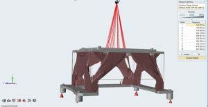
5 System Validation Large scale system models have been developed to validate the design and to ensure that requirements are met Systems are tested to ensure key performance parameters are met Test yields data which is used to validate the analytical models Test/Model discrepancies

6 How Bolted Joints Behave Developed by Joseph Shigley Joint and bolts act like springs Joint is modeled as a soft bolt spring in parallel with a stiff member joint Stress distribution modeled as frustum of a cone Load Cell

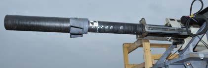
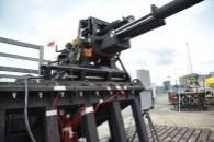
7 Small Scale Testing Constructed a simplified joint, representative of a large caliber weapon system Explored the effects of sensor placement on measured results Known load input Two primary configurations Equipment MTS Systems Corp. 810 Material Test System Dytran 1210C2 piezoelectric force sensor Only captures change in force, steady state forces dissipate

8 Small Scale Testing Test Case A Force sensor sandwiched between fixtures, with a machined washer Typical setup for a ring style force sensor May not be possible to install in this configuration Alignment critical designs Interface concerns
9 Small Scale Testing Force Sensor Results Positive force shows compression decreased at sensor Measured force is a decrease in joint preload Maximum force is 3,830 lbs. Approx. 77% of the force applied
10 Small Scale Testing Test Case B Less typical usage of force sensor Changed where the sensor is in the load path Necessary if the height of the joint cannot be changed without impacting the overall performance
11 Small Scale Testing Force Sensor Results Negative force shows compression increased at the sensor Measured force is an increase in bolt load Maximum force is 310 lbs. Approx. 6% of force applied
12 Small Scale Testing Summary Observer Effect Joint behavior is changed because of the added force sensor and change in bolt length Test Case A + Test Case B do not equal applied force Moving the sensor further changed the joint behavior Force sensors are not plug and play Hard to gather meaningful data using a force sensor out of the box Small scale testing is important Needed to correctly interpret results from a large scale test Can also be used to calibrate the sensors for the specific joint Other methods of modeling the joint may be more efficient than numerous physical tests
13 Finite Element Analysis (FEA) Benefits of Finite Element Analysis Characterizes the behavior of the system during the design of the system and interfaces with Computer Aided Design (CAD) software Identifies design flaws before a prototype is built Increases the likelihood of success for the weapon system Finite Element Analysis for Large Caliber Guns Advances in computing capability have allowed for highly detailed models of the entire weapon system Crucial that Finite Element Models are validated Both Small Scale and Large Scale CAD FEA Testing Design

14 Finite Element Analysis Finite Element Model (FEM) Finite Element Model was developed to be identical to the small scale test The load applied to the specimen was the same as the test, 5000 lbf. ramped over 25ms Data was collected for: Load cell force Bolt Load Force between every surface LS-DYNA was used for the finite element analysis using implicit time integration 5000 lbf 5000 lbf
15 Finite Element Analysis Finite Element Model (FEM) Multiple mesh densities were tested to determine the sensitivity of the results to the mesh Key components for success Number of elements through the thickness Number of integration points in the element How the bolt is defined

16 Finite Element Analysis Small Changes Can Result in Drastic Effects Bolts are typically modeled as 1-D Beams When modeling bolts, what will produce inaccurate results? Node location on a threaded hole? Do washers need to be modeled or are rigid elements good enough? Are 1-D bolts even accurate enough? Do bolts need to be modeled in 3D? Accuracy versus Cost More elements = More Degrees of Freedom More Degrees of Freedom = More Computational Cost
17 Finite Element Analysis Results Mesh Density At least 2 elements through the thickness Fully integrated elements Underintegrated elements are troublesome in a course mesh, as expected Modeling 1-D Bolts Thin washers can be replaced with rigid elements Accurate bolt length is imperative Threaded hole = ½ diameter
18 Conclusions Theoretical calculations are often over simplified and not capable of predicting joint loads accurately Joint loads can be easily underestimated during physical testing Instrumentation can change the joint behavior and often measures only part of the reaction load Can be overcome by calibrating the instrumentation for a specific joint, usually through small scale testing Finite Element Analysis can easily measure the entire reaction load Finite Element Models are sensitive to a number of variables Fine mesh densities and accurate bolt lengths greatly improve results Finite Element Models should be validated Comparing analytical models to controlled physical testing is a great way to prove accuracy
Modeling Bolted Connections. Marilyn Tomlin CAE COE / Siemens Corporation
 Modeling Bolted Connections Marilyn Tomlin CAE COE / Siemens Corporation Overview Bolted Connection Engineering Judgment Modeling Options Summary Typical Bolted Connection Gasket Bolt Nut Washer Technology
CHAPTER-10 DYNAMIC SIMULATION USING LS-DYNA
 DYNAMIC SIMULATION USING LS-DYNA CHAPTER-10 10.1 Introduction In the past few decades, the Finite Element Method (FEM) has been developed into a key indispensable technology in the modeling and simulation
Modelling Flat Spring Performance Using FEA
 Modelling Flat Spring Performance Using FEA Blessing O Fatola, Patrick Keogh and Ben Hicks Department of Mechanical Engineering, University of Corresponding author bf223@bath.ac.uk Abstract. This paper
Orbital forming of SKF's hub bearing units
 Orbital forming of SKF's hub bearing units Edin Omerspahic 1, Johan Facht 1, Anders Bernhardsson 2 1 Manufacturing Development Centre, AB SKF 2 DYNAmore Nordic 1 Background Orbital forming is an incremental
First Order Analysis for Automotive Body Structure Design Using Excel
 Special Issue First Order Analysis 1 Research Report First Order Analysis for Automotive Body Structure Design Using Excel Hidekazu Nishigaki CAE numerically estimates the performance of automobiles and
COSMOS. Connecting to Accurate, Efficient Assembly Analysis. SolidWorks Corporation. Introduction. Pin Connectors. Bolt Connectors.
 WHITE PAPER Connecting to Accurate, Efficient Assembly Analysis CONTENTS Introduction Pin Connectors Bolt Connectors Spring Connectors Spot Weld Connectors 1 2 4 7 8 SolidWorks Corporation INTRODUCTION
Technical. Recommended Compression and Tension. ISO/IEC / ANSI/NCSLI Z540.3 Accredited.
 ISO/IEC 17025 / ANSI/NCSLI Z540.3 Accredited Technical Paper Recommended Compression and Tension Adapters for P: (717) 843-0081 F: (717) 846-4193 info@mhforce.com Figure 1: Bent Rod End Not using the proper
Validation of a Finite Element Analysis (FEA) Model of a Nuclear Transportation Package under Impact Conditions
 Model of a Nuclear Transportation Package under Impact Conditions") Validation of a Finite Element Analysis (FEA) Model of a Nuclear Transportation Package under Impact Conditions Chris Berry Lead Engineering Analyst 11 th October 2016 Outline of presentation Background
Validation of a Finite Element Analysis (FEA) Model of a Nuclear Transportation Package under Impact Conditions Chris Berry Lead Engineering Analyst 11 th October 2016 Outline of presentation Background
Coupled Thermal-Structural Analysis of the Shippingport Nuclear Reactor Using Adaptive Remeshing in Abaqus/CAE
 Abaqus Technology Brief TB-06-ARCAE-1 Revised: April 2007. Coupled Thermal-Structural Analysis of the Shippingport Nuclear Reactor Using Adaptive Remeshing in Abaqus/CAE Summary Mesh construction is a
Introduction to ANSYS Mechanical
 Lecture 6 Modeling Connections 15.0 Release Introduction to ANSYS Mechanical 1 2012 ANSYS, Inc. February 12, 2014 Chapter Overview In this chapter, we will extend the discussion of contact control begun
March 5-8, 2017 Hilton Phoenix / Mesa Hotel Mesa, Arizona Archive Session 7
 March 5-8, 2017 Hilton Phoenix / Mesa Hotel Mesa, Arizona Archive Session 7 2017 BiTS Workshop Image: tonda / istock Copyright Notice The presentation(s)/poster(s) in this publication comprise the Proceedings
Lecture 5 Modeling Connections
 Lecture 5 Modeling Connections 16.0 Release Introduction to ANSYS Mechanical 1 2015 ANSYS, Inc. February 27, 2015 Chapter Overview In this chapter, we will extend the discussion of contact control begun
Through Process Modelling of Self-Piercing Riveting
 8 th International LS-DYNA User Conference Metal Forming (2) Through Process Modelling of Self-Piercing Riveting Porcaro, R. 1, Hanssen, A.G. 1,2, Langseth, M. 1, Aalberg, A. 1 1 Structural Impact Laboratory
Using Computer Aided Engineering Processes in Packaging Design Development
 Using Computer Aided Engineering Processes in Packaging Design Development Jose Martinez, Miguel Angel Garcia Jose Luis Moreno Vicencio & Hugo Miranda Mabe, Mexico Mahesh Patel, Andrew Burkhalter, Eric
NDIA Armaments Forum Indianapolis, Indiana
 NAVAL SURFACE WARFARE CENTER DAHLGREN DIVISION NDIA Armaments Forum Indianapolis, Indiana Analysis of 25mm PGU-47 APHEI-T Projectile Against Wall Targets GUN & ELECTRIC WEAPON SYSTEMS DEPARTMENT (E) Presented
IDENTIFYING WORST CASE DESIGNS THROUGH A COMBINED STRATEGY OF COMPUTATIONAL MODELING, STATISTICAL METHODS, AND BENCH TOP TESTS
 IDENTIFYING WORST CASE DESIGNS THROUGH A COMBINED STRATEGY OF COMPUTATIONAL MODELING, STATISTICAL METHODS, AND BENCH TOP TESTS Payman Afshari Andrew Dooris Pat Fatyol DePuy Synthes Spine, a Johnson and
An Analyst s Guide to Resolving Common Geometry Problems
 An Analyst s Guide to Resolving Common Geometry Problems IN THIS WEBINAR: PRESENTED BY: Refining a thin-walled solid wing box structure with common imperfections Aligning and associating geometry to a
Belleville Spring Washer Series
 Belleville Spring Washer Series High Load in Small Spaces VARIOUS CONFIGURATIONS OF BELLEVILLE WASHERS Single ONE WASHER Parallel ALL WASHERS STACKED THE SAME WAY Series ALL WASHERS STACKED OPPOSITE EACH
Recent Advances on Higher Order 27-node Hexahedral Element in LS-DYNA
 14 th International LS-DYNA Users Conference Session: Simulation Recent Advances on Higher Order 27-node Hexahedral Element in LS-DYNA Hailong Teng Livermore Software Technology Corp. Abstract This paper
Simulation of Overhead Crane Wire Ropes Utilizing LS-DYNA
 Simulation of Overhead Crane Wire Ropes Utilizing LS-DYNA Andrew Smyth, P.E. LPI, Inc., New York, NY, USA Abstract Overhead crane wire ropes utilized within manufacturing plants are subject to extensive
COMPUTATIONAL SIMULATION OF BLAST LOADING IN AN OPEN CYLINDER MODEL USING ANSYS AND LS-DYNA
 COMPUTATIONAL SIMULATION OF BLAST LOADING IN AN OPEN CYLINDER MODEL USING ANSYS AND LS-DYNA Ramprashad Prabhakaran Graduate Student Department of Mechanical Engineering University of Nevada, Las Vegas
Development and Validation of Bolted Connection Modeling in LS-DYNA for Large Vehicle Models
 14 th International LS-DYNA Users Conference Session: Connections Development and Validation of Bolted Connection Modeling in LS-DYNA for Large Vehicle Models Michalis Hadjioannou, David Stevens, Matt
The Role of Finite Element Analysis in Light Aircraft Design and Certification
 The Role of Finite Element Analysis in Light Aircraft Design and Certification Nigel Bamber Wey Valley Aeronautics Ltd www.weyvalleyaero.co.uk Engineering Consultancy Civil and Military Aerospace and Motorsport
ixcube 4-10 Brief introduction for membrane and cable systems.
 ixcube 4-10 Brief introduction for membrane and cable systems. ixcube is the evolution of 20 years of R&D in the field of membrane structures so it takes a while to understand the basic features. You must
Stress Intensity Factors for Finite Width Plates
 Stress Intensity Factors for Finite Width Plates 10 September 2013 AFGROW Workshop 2013 US Air Force Academy CAStLE Matthew Hammond * Scott Fawaz * James Greer, Technical Director, CAStLE ** *SAFE Inc.
SIMPACKS s FEA Interface New Features in 8.5 and Further Development. Stefan Dietz, INTEC GmbH
 SIMPACKS s FEA Interface New Features in 8.5 and Further Development Stefan Dietz, INTEC GmbH Contents New Features in 8.5 integration into SIMPACK GUI generalised file interface between FE-codes and SIMPACK
Virtual Die Tryout of Miniature Stamping Parts
 4 th European LS-DYNA Users Conference Metal Forming III Virtual Die Tryout of Miniature Stamping Parts Authors: Ming-Chang Yang and Tien-Chi Tsai Correspondence: Ming-Chang Yang Metal Industries R&D Center
Quick Start Guide to midas NFX
 Quick Start Guide to midas NFX This guide is made for non-experienced FEA users. It provides basic knowledge needed to run midas NFX successfully and begin your analysis. Experienced FEA analysts can also
ABOUT FEATURES OF SIMULATION MODULE IN SOLIDWORKS
 ABOUT FEATURES OF SIMULATION MODULE IN SOLIDWORKS prof.phd.eng. Cătălin IANCU Engineering and Sustainable Development Faculty, C-tin Brâncuşi Univ. of Tg-Jiu, ciancu@utgjiu.ro Abstract: In this paper are
Roger Wende Acknowledgements: Lu McCarty, Johannes Fieres, Christof Reinhart. Volume Graphics Inc. Charlotte, NC USA Volume Graphics
 Roger Wende Acknowledgements: Lu McCarty, Johannes Fieres, Christof Reinhart Volume Graphics Inc. Charlotte, NC USA 2018 Volume Graphics VGSTUDIO MAX Modules Inline Fiber Orientation Analysis Nominal/Actual
Using Photo Modeling to Obtain the Modes of a Structure
 Using Photo Modeling to Obtain the Modes of a Structure Shawn and Mark Richardson, Vibrant Technology, Inc., Scotts Valley, California Photo modeling technology has progressed to the point where a dimensionally
COMPUTATIONAL AND EXPERIMENTAL INTERFEROMETRIC ANALYSIS OF A CONE-CYLINDER-FLARE BODY. Abstract. I. Introduction
 COMPUTATIONAL AND EXPERIMENTAL INTERFEROMETRIC ANALYSIS OF A CONE-CYLINDER-FLARE BODY John R. Cipolla 709 West Homeway Loop, Citrus Springs FL 34434 Abstract A series of computational fluid dynamic (CFD)
Unclassified Unlimited Release UUR
 Shock-hardened Penetrator Data Recorder to Support Hard-Target Fuze Development SAND2016-3004 C 59th Annual NDIA Fuze Conference, Charleston, SC Mike Partridge, Shane Curtis Advanced Fuzing Technologies
Non-Linear Analysis of Bolted Flush End-Plate Steel Beam-to-Column Connection Nur Ashikin Latip, Redzuan Abdulla
 Non-Linear Analysis of Bolted Flush End-Plate Steel Beam-to-Column Connection Nur Ashikin Latip, Redzuan Abdulla 1 Faculty of Civil Engineering, Universiti Teknologi Malaysia, Malaysia redzuan@utm.my Keywords:
Nastran CBUSH Element Orientation Blog Post pdf
 Nastran CBUSH Element Orientation Blog Post pdf Author: Surya Batchu Senior Stress Engineer Founder, STRESS EBOOK LLC. http://www.stressebook.com 1 P a g e Nastran CBUSH Element Orientation The Nastran
AutoMesher for LS-DYNA Vehicle Modelling
 13 th International LS-DYNA Users Conference Session: Computing Technology AutoMesher for LS-DYNA Vehicle Modelling Ryan Alberson 1, David Stevens 2, James D. Walker 3, Tom Moore 3 Protection Engineering
Keywords- bolted joints, member stiffness, finite element analysis, axisymmetric model.
 Finite Element Based Member Stiffness Evaluation of Axisymmetric Bolted Joint Mr. Chetan Chirmurkar Department Of Mechanical Engg. (Design Engg.), Savitribai Phule Pune University, D.Y.P.S.O.E. Lohegaon
Final project: Design problem
 ME309 Homework #5 Final project: Design problem Select one of the analysis problems listed below to solve. Your solution, along with a description of your analysis process, should be handed in as a final
Spotweld Failure Prediction using Solid Element Assemblies. Authors and Correspondence: Abstract:
 Spotweld Failure Prediction using Solid Element Assemblies Authors and Correspondence: Skye Malcolm Honda R&D Americas Inc. Email smalcolm@oh.hra.com Emily Nutwell Altair Engineering Email enutwell@oh.hra.com
Chapter 5 Modeling and Simulation of Mechanism
 Chapter 5 Modeling and Simulation of Mechanism In the present study, KED analysis of four bar planar mechanism using MATLAB program and ANSYS software has been carried out. The analysis has also been carried
CHAPTER 7 SIMULATIONS OF EXPERIMENTAL WORK PERFORMED ON COMPOSITE SPECIMENS BY USING ANSYS
 275 CHAPTER 7 SIMULATIONS OF EXPERIMENTAL WORK PERFORMED ON COMPOSITE SPECIMENS BY USING ANSYS 7.1 INTRODUCTION 275 7.2 EXPERIMENTAL CONFIGURATIONS 275 7.2.1 Tensile Test 275 7.2.2 Compression Test 278
Design of a Precision Robot Wrist Interface. Patrick Willoughby Advisor: Alexander Slocum MIT Precision Engineering Research Group
 Design of a Precision Robot Wrist Interface Patrick Willoughby Advisor: Alexander Slocum MIT Precision Engineering Research Group Project Summary Problem: Current bolted robot wrist replacements are inaccurate,
Offshore Platform Fluid Structure Interaction (FSI) Simulation
 Simulation") Offshore Platform Fluid Structure Interaction (FSI) Simulation Ali Marzaban, CD-adapco Murthy Lakshmiraju, CD-adapco Nigel Richardson, CD-adapco Mike Henneke, CD-adapco Guangyu Wu, Chevron Pedro M. Vargas,
Offshore Platform Fluid Structure Interaction (FSI) Simulation Ali Marzaban, CD-adapco Murthy Lakshmiraju, CD-adapco Nigel Richardson, CD-adapco Mike Henneke, CD-adapco Guangyu Wu, Chevron Pedro M. Vargas,
2: Static analysis of a plate
 2: Static analysis of a plate Topics covered Project description Using SolidWorks Simulation interface Linear static analysis with solid elements Finding reaction forces Controlling discretization errors
Technical Report Example (1) Chartered (CEng) Membership
 Chartered (CEng) Membership") Technical Report Example (1) Chartered (CEng) Membership A TECHNICAL REPORT IN SUPPORT OF APPLICATION FOR CHARTERED MEMBERSHIP OF IGEM DESIGN OF 600 (103 BAR) 820MM SELF SEALING REPAIR CLAMP AND VERIFICATION
Technical Report Example (1) Chartered (CEng) Membership A TECHNICAL REPORT IN SUPPORT OF APPLICATION FOR CHARTERED MEMBERSHIP OF IGEM DESIGN OF 600 (103 BAR) 820MM SELF SEALING REPAIR CLAMP AND VERIFICATION
ECE421: Electronics for Instrumentation
 ECE421: Electronics for Instrumentation Lecture #8: Introduction to FEA & ANSYS Mostafa Soliman, Ph.D. March 23 rd 2015 Mostafa Soliman, Ph.D. 1 Outline Introduction to Finite Element Analysis Introduction
Simulation of shock absorbers behavior during a 9m drop test
 Simulation of shock absorbers behavior during a 9m drop test Fabien Collin (TN International) Abstract TN International designs, manufactures and licenses packages for the transportation of radioactive
PMLD-5000XLT FVS-5000XLT FCS-5000XLT
 Force Calibration Systems Calibration labs worldwide choose Norton Global Force Calibration Systems to calibrate their load cells and force gages. Each system is engineered to meet rigorous standards for
Solid Modeling of Directed-Energy Systems
 Directed Energy Technology, Modeling, and Assessment Solid Modeling of Directed-Energy Systems By Joseph F. Sharrow 58 Not long ago, around the mid-1980s, development of most new mechanical systems such
CHAPTER 1. Introduction
 ME 475: Computer-Aided Design of Structures 1-1 CHAPTER 1 Introduction 1.1 Analysis versus Design 1.2 Basic Steps in Analysis 1.3 What is the Finite Element Method? 1.4 Geometrical Representation, Discretization
CAD - How Computer Can Aid Design?
 CAD - How Computer Can Aid Design? Automating Drawing Generation Creating an Accurate 3D Model to Better Represent the Design and Allowing Easy Design Improvements Evaluating How Good is the Design and
COMPUTER AIDED ENGINEERING. Part-1
 COMPUTER AIDED ENGINEERING Course no. 7962 Finite Element Modelling and Simulation Finite Element Modelling and Simulation Part-1 Modeling & Simulation System A system exists and operates in time and space.
The concise guide to Nastran Rigid Elements
 The concise guide to Nastran Rigid Elements The Nastran group of elements often described as the "Rigid elements" are very useful engineering analysis tools. "Rigid Element" is a slight misnomer, but the
Introduction to Engineering Analysis
 Chapter 1 Introduction to Engineering Analysis This chapter introduces you to the Stress Analysis and Dynamic Simulation environments. You learn how digital prototyping can be used to simulate your designs
MODELING OF A MICRO-GRIPPER COMPLIANT JOINT USING COMSOL MULTIPHYSICS SIMULATION
 MODELING OF A MICRO-GRIPPER COMPLIANT JOINT USING COMSOL MULTIPHYSICS SIMULATION Mihăiţă Nicolae ARDELEANU, Veronica DESPA, Ioan Alexandru IVAN Valahia University from Targoviste E-mail: mihai.ardeleanu@valahia.ro,
User s Manual. Models Digital Force Gauge. Additional User Manual Translations available at
 User s Manual Models 475055 Digital Force Gauge Additional User Manual Translations available at www.extech.com Introduction Congratulations on your purchase of Extech s Model 475055 Digital Force Gauge
Finite Element Analysis and Structure Optimal Design of the Column of Deep-Hole Drilling Machine
 Vol. 5, No. 5; October 2011 Finite Element Analysis and Structure Optimal Design of the Column of Deep-Hole Drilling Machine Baohui Li College of Mechanical Engineering, University of Shanghai for Science
MEEN 3360 Engineering Design and Simulation Spring 2016 Homework #1 This homework is due Tuesday, February 2, From your book and other
 MEEN 3360 Engineering Design and Simulation Spring 2016 Homework #1 This homework is due Tuesday, February 2, 2016 1.0 From your book and other sources, write a paragraph explaining CFD and finite element
Week 12 - Lecture Mechanical Event Simulation. ME Introduction to CAD/CAE Tools
 Week 12 - Lecture Mechanical Event Simulation Lecture Topics Mechanical Event Simulation Overview Additional Element Types Joint Component Description General Constraint Refresh Mesh Control Force Estimation
ENHANCED FRAGMENTATION MODELING
 ENHANCED FRAGMENTATION MODELING Peter Rottinger*, Richard Fong, William Ng U.S. ARMY ARDEC Picatinny Arsenal, NJ, 07806 ABSTRACT Enhancing the fragmentation capability of current and future projectiles
OPTIMIZATION OF STIFFENED LAMINATED COMPOSITE CYLINDRICAL PANELS IN THE BUCKLING AND POSTBUCKLING ANALYSIS.
 OPTIMIZATION OF STIFFENED LAMINATED COMPOSITE CYLINDRICAL PANELS IN THE BUCKLING AND POSTBUCKLING ANALYSIS. A. Korjakin, A.Ivahskov, A. Kovalev Stiffened plates and curved panels are widely used as primary
Matching Real World Results
 Matching Real World Results Randy Dreher FFE Minerals Inc. Jan Janssen, Doug Farnell, Stephen Thompson Farnell-Thompson Applied Technologies Inc Abstract Comparing measured results to those generated by
EDjunior Dynamometer User s Manual
 EDjunior Dynamometer User s Manual 2 EDjunior Dynamometer User s Manual Weigh Bar is a registered trademark of Weigh-Tronix Inc. 05/16/06 EDJR_U.P65 PN 29810-0017D e1 Printed in USA Table of Contents Table
SOLIDWORKS Simulation
 SOLIDWORKS Simulation Length: 3 days Prerequisite: SOLIDWORKS Essentials Description: SOLIDWORKS Simulation is designed to make SOLIDWORKS users more productive with the SOLIDWORKS Simulation Bundle. This
AUTOMATED METHODOLOGY FOR MODELING CRACK EXTENSION IN FINITE ELEMENT MODELS
 AUTOMATED METHODOLOGY FOR MODELING CRACK THEME Structural Analysis - Durability, Fatigue & Fracture. James J. Kosloski Senior Engineering Manager - CAE Associates Dr. Michael Bak Senior Engineering Manager
What makes Bolt Self-loosening Predictable?
 What makes Bolt Self-loosening Predictable? Abstract Dr.-Ing. R. Helfrich, Dr.-Ing. M. Klein (INTES GmbH, Germany) In mechanical engineering, bolts are frequently used as standard fastening elements, which
Numerical Simulation of Aircraft Seat Compliance Test using LS-DYNA Implicit Solver
 Numerical Simulation of Aircraft Seat Compliance Test using LS-DYNA Implicit Solver Satish Pathy LSTC, Livermore, CA Thomas Borrvall DYNAmore Nordic AB, Linköping, Sweden Abstract With the possibility
PTC Creo Simulate. Features and Specifications. Data Sheet
 PTC Creo Simulate PTC Creo Simulate gives designers and engineers the power to evaluate structural and thermal product performance on your digital model before resorting to costly, time-consuming physical
FEA and Topology Optimization of an Engine Mounting Bracket
 International Journal of Current Engineering and Technology E-ISSN 2277 4106, P-ISSN 2347 5161 2016 INPRESSCO, All Rights Reserved Available at http://inpressco.com/category/ijcet Research Article Sanket
LS-DYNA s Linear Solver Development Phase 2: Linear Solution Sequence
 LS-DYNA s Linear Solver Development Phase 2: Linear Solution Sequence Allen T. Li 1, Zhe Cui 2, Yun Huang 2 1 Ford Motor Company 2 Livermore Software Technology Corporation Abstract This paper continues
Flexible Body Suspension System Modeling and Simulation Using MD Nastran SOL700 in VPG Environment
 9 th International LS-DYNA Users Conference Crash/Safety (4) Flexible Body Suspension System Modeling and Simulation Using SOL700 in VPG Environment Casey Heydari, Ted Pawela MSC.Software Corporation Santa
INDUSTRIAL SYSTEM DEVELOPMENT FOR VOLUMETRIC INTEGRITY
 INDUSTRIAL SYSTEM DEVELOPMENT FOR VOLUMETRIC INTEGRITY VERIFICATION AND ANALYSIS M. L. Hsiao and J. W. Eberhard CR&D General Electric Company Schenectady, NY 12301 J. B. Ross Aircraft Engine - QTC General
Auto Spot Weld FE Connection Using TCL Script For Process Automation
 Auto Spot Weld FE Connection Using TCL Script For Process Automation Vishal Gole Technical lead-cae Vishal.G.Gole Sagar J Patel CAE engineer Sagar.J.Patel Pravinkumar Sonavane Technical lead-cae Pravinkumar.Sonavane
Common Mistakes And Errors In Modelling
 Common Mistakes And Errors In Modelling The modeling pitfalls listed below can be considered as appetizers with the intention of making you think (and worry) more about the model set-up. More in-depth
(Based on a paper presented at the 8th International Modal Analysis Conference, Kissimmee, EL 1990.)
") Design Optimization of a Vibration Exciter Head Expander Robert S. Ballinger, Anatrol Corporation, Cincinnati, Ohio Edward L. Peterson, MB Dynamics, Inc., Cleveland, Ohio David L Brown, University of Cincinnati,
Design Optimization of a Vibration Exciter Head Expander Robert S. Ballinger, Anatrol Corporation, Cincinnati, Ohio Edward L. Peterson, MB Dynamics, Inc., Cleveland, Ohio David L Brown, University of Cincinnati,
A Six Degree of Freedom, Piezoelectrically Actuated Translation Stage
 A Six Degree of Freedom, Piezoelectrically Actuated Translation Stage Richard M. Seugling, Roy H.R. Jacobs, Stuart T. Smith, Lowell P. Howard, Thomas LeBrun Center for Precision Metrology, UNC Charlotte,
SAMCEF for ROTORS. Chapter 3.2: Rotor modeling. This document is the property of SAMTECH S.A. MEF A, Page 1
 SAMCEF for ROTORS Chapter 3.2: Rotor modeling This document is the property of SAMTECH S.A. MEF 101-03-2-A, Page 1 Table of contents Introduction Introduction 1D Model 2D Model 3D Model 1D Models: Beam-Spring-
Correlation of the Federal Motor Vehicle Safety Standard 225 (FMVSS225) Requirement of an Automotive Seat System Using LS-DYNA
 Requirement of an Automotive Seat System Using LS-DYNA") 7 th International LS-DYNA Users Conference Simulation Technology (2) Correlation of the Federal Motor Vehicle Safety Standard 225 (FMVSS225) Requirement of an Automotive Seat System Using LS-DYNA Frank
7 th International LS-DYNA Users Conference Simulation Technology (2) Correlation of the Federal Motor Vehicle Safety Standard 225 (FMVSS225) Requirement of an Automotive Seat System Using LS-DYNA Frank
XSLIDE. XSlide Positioning System. Manual and Motorized. Compact Positioning Stage. Long life, precise movement, greater value
 XSlide Positioning System Long life, precise movement, greater value Manual and Motorized Compact Positioning Stage XSLIDE Ideal for limited space applications Velmex Versatility Velmex positioning products
Structural re-design of engine components
 Structural re-design of engine components Product design cycle Design Development Testing Structural optimization Product knowledge Design freedom 2/18 Structural re-design of engine components Product
3D Waterjet Cutting: Adding a New Dimension of Opportunity. Tim Fabian & Jonathan Meas Flow International Corporation
 3D Waterjet Cutting: Adding a New Dimension of Opportunity Tim Fabian & Jonathan Meas Flow International Corporation Agenda Challenges unique to multi-axis waterjet cutting Utilizing multi-axis waterjet
Guidelines for proper use of Plate elements
 Guidelines for proper use of Plate elements In structural analysis using finite element method, the analysis model is created by dividing the entire structure into finite elements. This procedure is known
Ideas on Applying Very Fine Models in Dummy Model Development
 10 th International LS-DYNA Users Conference Crash/Safety (1) Ideas on Applying Very Fine Models in Dummy Model Development Uli Franz 1, Alexander Gromer 1, Matthias Walz 2, Jens Zschieschack 1, Yupeng
Calibration of Nonlinear Viscoelastic Materials in Abaqus Using the Adaptive Quasi-Linear Viscoelastic Model
 Calibration of Nonlinear Viscoelastic Materials in Abaqus Using the Adaptive Quasi-Linear Viscoelastic Model David B. Smith *, Uday Komaragiri **, and Romil Tanov ** ** * Ethicon Endo-Surgery, Inc., Cincinnati,
Modeling Flexibility with Spline Approximations for Fast VR Visualizations
 Modeling Flexibility with Spline Approximations for Fast VR Visualizations Abstract: Kevin Tatur a and Renate Sitte a a Faculty of Engineering and Information Technology, Griffith University, Gold Coast,
Abstract. Introduction:
 Abstract This project analyzed a lifecycle test fixture for stress under generic test loading. The maximum stress is expected to occur near the shrink fit pin on the lever arm. The model was constructed
FINITE ELEMENT MODELING OF THICK PLATE PENETRATIONS IN SMALL CAL MUNITIONS
 FINITE ELEMENT MODELING OF THICK PLATE PENETRATIONS IN SMALL CAL MUNITIONS Raymond Chaplin RDAR-MEM-I Picatinny Arsenal, NJ raymond.c.chaplin@us.army.mil 973-724-8562 Why Finite Element Modeling? Reduced
Simulating Underbelly Blast Events using Abaqus/Explicit - CEL
 U.S. Army Research, Development and Engineering Command Simulating Underbelly Blast Events using Abaqus/Explicit - CEL J. Jablonski, P. Carlucci (U.S. Army ARDEC) R. Thyagarajan (U.S. Army TARDEC) B. Nandi,
What s new in Femap 9.3
 What s new in Femap 9.3 fact sheet www.ugs.com/femap Summary Femap version 9.3 is the latest release of UGS robust pre and post processor for engineering finite element analysis (FEA). Femap software is
Engineering Effects of Boundary Conditions (Fixtures and Temperatures) J.E. Akin, Rice University, Mechanical Engineering
 J.E. Akin, Rice University, Mechanical Engineering") Engineering Effects of Boundary Conditions (Fixtures and Temperatures) J.E. Akin, Rice University, Mechanical Engineering Here SolidWorks stress simulation tutorials will be re-visited to show how they
Engineering Effects of Boundary Conditions (Fixtures and Temperatures) J.E. Akin, Rice University, Mechanical Engineering Here SolidWorks stress simulation tutorials will be re-visited to show how they
ME 345: Modeling & Simulation. Introduction to Finite Element Method
 ME 345: Modeling & Simulation Introduction to Finite Element Method Examples Aircraft 2D plate Crashworthiness 2 Human Heart Gears Structure Human Spine 3 F.T. Fisher, PhD Dissertation, 2002 Fluid Flow
NUMERICAL COUPLING BETWEEN DEM (DISCRETE ELEMENT METHOD) AND FEA (FINITE ELEMENTS ANALYSIS).
 AND FEA (FINITE ELEMENTS ANALYSIS).") NUMERICAL COUPLING BETWEEN DEM (DISCRETE ELEMENT METHOD) AND FEA (FINITE ELEMENTS ANALYSIS). Daniel Schiochet Nasato - ESSS Prof. Dr. José Roberto Nunhez Unicamp Dr. Nicolas Spogis - ESSS Fabiano Nunes
NUMERICAL COUPLING BETWEEN DEM (DISCRETE ELEMENT METHOD) AND FEA (FINITE ELEMENTS ANALYSIS). Daniel Schiochet Nasato - ESSS Prof. Dr. José Roberto Nunhez Unicamp Dr. Nicolas Spogis - ESSS Fabiano Nunes
Method of Finite Elements I
 Institute of Structural Engineering Page 1 Held by Prof. Dr. E. Chatzi, Dr. P. Steffen Assistants: Adrian Egger (HIL E 13.3), Harry Mylonas (HIL H33.1), Konstantinos Tatsis (HIL H33.1) Lectures homepage:
Problem (From Shigley and Mischke Mechanical Engineering Design)
") Problem 7-20 (From Shigley and Mischke Mechanical Engineering Design) Start by building the part shown in problem 7-20 in the textbook, make sure you are in English (IPS) units. Next, apply a material
Problem 7-20 (From Shigley and Mischke Mechanical Engineering Design) Start by building the part shown in problem 7-20 in the textbook, make sure you are in English (IPS) units. Next, apply a material
Wave Propagation Correlations between Finite Element Simulations and Tests for Enhanced Structural Health Monitoring
 6th European Workshop on Structural Health Monitoring - Tu.4.D.4 More info about this article: http://www.ndt.net/?id=14108 Wave Propagation Correlations between Finite Element Simulations and Tests for
SOLIDWORKS. SOLIDWORKS Simulation. Dassault Systèmes SolidWorks Corporation 175 Wyman Street Waltham, MA U.S.A.
 SOLIDWORKS SOLIDWORKS Simulation Dassault Systèmes SolidWorks Corporation 175 Wyman Street Waltham, MA 02451 U.S.A. 1995-2017, Dassault Systemes SolidWorks Corporation, a Dassault Systèmes SE company,
Three-dimensional Simulation of Robot Path and Heat Transfer of a TIG-welded Part with Complex Geometry
 Three-dimensional Simulation of Robot Path and Heat Transfer of a TIG-welded Part with Complex Geometry Daneshjo Naqib Ing. Daneshjo Naqib, PhD. Technical University of Košice, Fakulty of Mechanical Engineering,
D DAVID PUBLISHING. Stability Analysis of Tubular Steel Shores. 1. Introduction
 Journal of Civil Engineering and Architecture 1 (216) 563-567 doi: 1.17265/1934-7359/216.5.5 D DAVID PUBLISHING Fábio André Frutuoso Lopes, Fernando Artur Nogueira Silva, Romilde Almeida de Oliveira and
Stress Analysis of Bolted Joints Part II. Contact and Slip Analysis of a Four Bolt Joint
 Modern Mechanical Engineering, 2014, 4, 46-55 Published Online February 2014 (http://www.scirp.org/journal/mme) http://dx.doi.org/10.4236/mme.2014.41006 Stress Analysis of Bolted Joints Part II. Contact
Modeling and Simulation for Aircraft Structural Repair Using Modern FEA Tools
 Modeling and Simulation for Aircraft Structural Repair Using Modern FEA Tools December 19-22, 2011 and January 9-12, 2012 Kuang-Hua Chang, Ph.D. Williams Presidential Professor School of Aerospace and