Roger Wende Acknowledgements: Lu McCarty, Johannes Fieres, Christof Reinhart. Volume Graphics Inc. Charlotte, NC USA Volume Graphics
|
|
|
- Homer Fox
- 5 years ago
- Views:
Transcription
1 Roger Wende Acknowledgements: Lu McCarty, Johannes Fieres, Christof Reinhart Volume Graphics Inc. Charlotte, NC USA 2018 Volume Graphics


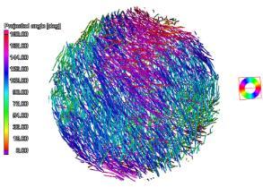
2 VGSTUDIO MAX Modules Inline Fiber Orientation Analysis Nominal/Actual Comparsion Wall Thickness Analysis Foam Structure Analysis Metrology Structural Simulation Porosity/Inclusion Analysis Transport Phenomena NDT in Canada 2018 June Halifax, NS


3 Simplified Part Workflow Concept Design Manufacture Validate Bracket CAE - Material FEM - Process Forge - Cast - Mold Machine - Additive Measure - Test Ship

4 Simple Bracket Basic Design Criteria 3 Point Design Dimensionally Correct AL6061-T6 Aluminum 220 Newton Force Load Force Fixed
5 Simple Bracket Basic Design Result Process: Machine Stock Weight: 290.7g Von Mises Stress Scale: 0 3e+7 Analysis: Good Results Courtesy of ANSYS Discovery Live


6 Simple Bracket ANSYS result compared to VGSTUDIO MAX Structural Mechanical Simulation (SMS) Result
 Von Mises Stress Scale: 0 3e+7 Analysis: Good Results Courtesy of ANSYS")
7 Simple Bracket Modified Design Result Process: Machine (pocketed) from Casting Weight: 174.1g (40% reduction) Von Mises Stress Scale: 0 3e+7 Analysis: Good Results Courtesy of ANSYS Discovery Live
 Von Mises Stress Scale: 0 3e+7 Analysis: Simulate with CT?")
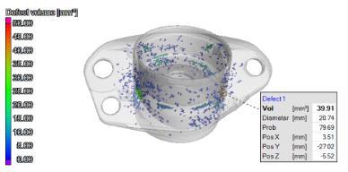
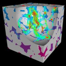
8 Simple Bracket Modified Actual Result Process: Machine (pocketed) from Casting Weight: 174.1g (40% reduction) Von Mises Stress Scale: 0 3e+7 Analysis: Simulate with CT? Analysis: Simulate with CT!!! Void Detection Structural Simulation with Defects
9 Bracket Summary Iterating between design and manufacturing phases produce results that help to define the final design and manufacturing process. Traditional CAE tools prove invaluable during the design phase. Traditional CAE tools require an STL with defects included, typically a low resolution mesh to compute FEA. VGSTUDIO MAX provides multiple analyses of a CT scanned part in one application. Defects of size and impurity are utilized when processing FEA on a CT scanned part with Structural Mechanical Simulation. Structural Mechanical Simulation uses voxels, not facets (meshless) to analyze complex structures accurately.

10 Additive Manufacturing contains Defects Discoverable using CT & VGStudio MAX


11 Additive Manufacturing (AM) AM is on its way to establish itself as additional production tool in various industries toolboxes. CT is used as an inspection tool for AM for many obvious reasons. We at VG have seen AM driving industry segments in: Aerospace Automotive Medical Devices Industrial Machinery
12 Addictive Additive The only rapid growing Industry in Manufacturing 2016: 5 Billion 2020: 80 Billion 2030: 800 Billion Average growth between 30% and 50% Their growth will support our growth NDT in Canada 2018 June Halifax, NS

13 The Advantages of 3D Printing 1. Design Freedom 2. Complex Geometry 3. Minimal Tooling 4. Weight Optimization 5. Reduction of SKUs 6. Rapid Prototyping 7. High Value / Low Volume Time to Market Image courtesy of Nettfabb
 model is often a challenge.")

14 Mechanical Simulation of CT data In the past we learned calculating stress analysis on real, non CAD data in the traditional way can be quite complicated. Customers have stated several times, that meshing the data into a suitable Finite Element (FE) model is often a challenge. Generating usable FE meshes from CT is a complex process itself, that can take longer than the actual FE calculation. VG has been asked many times to export geometries as STL meshes so that they can be integrated into FE models and calculations. But the defect data was often on a too small scale compared to the FE simulation grid cell size. NDT in Canada 2018 June Halifax, NS
15 The challenges of AM Dimensions Outside Dimensions Hidden Dimensions Inside Porosity / Voids Inclusions Cracks Density Lacks of Fusion Wall thickness Lattice Analyses Surface Quality Residual Stresses Dimensional and Defects caused by Energy Density Uneven cooling Buckling of thin walls Warping by thermal stress & rapid solidification Distortion / lift off due to residual stresses Burn / Melt through Powder Contamination Powder Inconsistencies Image courtesy of Netfabb NDT in Canada 2018 June Halifax, NS

16 CT versus CMM & Optical Scanners CT Dimensions Outside Dimensions Hidden Dimensions Inside Porosity / Voids Inclusions Cracks Density Lacks of Fusion Wall thickness Lattice Analyses Surface Quality CMM / Optical Scanner Dimensions Outside Dimensions Hidden Dimensions Inside Porosity / Voids Inclusions Cracks Density Lacks of Fusion Wall thickness Lattice Analyses Surface Quality NDT in Canada 2018 June Halifax, NS
17 Simple Bracket Optimized Design Result Process: Additive Manufacturing Weight: 71.7g (75% reduction) Von Mises Stress Scale: 0 3e+7 Analysis: Good Optimized model via FEA courtesy of Frustum Generate
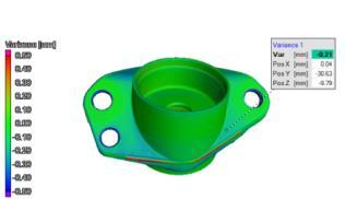
 Von Mises Stress Scale: 0 3e+7 Analysis: Marginal Deviation Analysis > Shrinkage Edge Rounding Defect")
18 Simple Bracket Optimized Actual Result Process: Additive Manufacturing Weight: 71.7g (75% reduction) Von Mises Stress Scale: 0 3e+7 Analysis: Marginal Deviation Analysis > Shrinkage Edge Rounding Defect Analysis > Voids found SMS Analysis > Strain detected


19 VGSM Stress Analysis Simple steps how to: Open your VGL data set or import your data and apply a surface determination. Perform a Porosity/Inclusion Analysis. Create an ROI where the part is fixed and an ROI where force is applied. Select the SMS command. Apply the material properties. Select the Force type, and the Fixed / Load ROIs. Define Force Direction and Magnitude. Add Porosity Analysis. Select Visualizations. Calculate. NDT in Canada 2018 June Halifax, NS


20 Stress Analysis Results There are numerous result visualizations, all visualizations have their own color bar and scene tree entry. For Volumes Force Lines Magnitude of Displacement Max. Principal Stress Max. Shear Stress Von Mises Stress Also if a CAD SMS is available Comparison of CAD Displacement Comparison of CAD Principal Stress Comparison of CAD Shear Stress Comparison of CAD Von Mises Stress NDT in Canada 2018 June Halifax, NS


21 Stress Analysis Results Statistical results Histograms for each visualization Hot spots
22 Stress Analysis Tool Validation Can we trust in the calculated results??????????


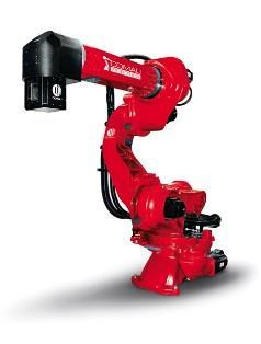
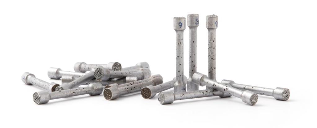
23 Stress Analysis Tool Validation To validate our new tool we performed classical tension rod experiments. The rods were built by Additive Manufacturing in Aluminum by Concept Laser in Lichtenfels. Using VGSTUDIO MAX we designed 6 different kind of tension rods with 75, 125 or 250 pores in two different random pore distributions each. We imported the tension rod template in STL file format, converted it into a voxel data set, inserted voids, and converted it back to STL for AM. Concept Laser printed 3 samples of each kind in CL 31 Aluminium. The parts have not been heat-treated. NDT in Canada 2018 June Halifax, NS 23


24 Stress Analysis Tool Validation Before testing all 18 samples have been CT scanned.
25 Tension Rods - Pull Test Concept Laser performed pull tests on all 18 samples.


26 Stress Analysis Tool Validation In parallel we performed our Stress Analysis on all 18 CT data sets and calculated the predicted tensile strength.

27 Validation Results Here are the results: The excellent correlation results between experiment and simulation Prediction data has been scaled by a uniform scaling factor. Error bars indicate the Std. Dev. within a set of 3 samples.
28 Validation Results Here are the results displayed as scatter plot. Tensile Strength average of 3 We can see that the strength of the rods do not depend on the total number of pores only but on their distribution within the sample as well. The sample with 125 pores shows a higher tensile strength in the experiment than the sample with 75 pores and we can predict that with our simulations! Prediction data has been scaled by a uniform scaling factor.
 with their additive LaserCUSING process.")
 / Lightweight natural construction solutions can be generated almost 1:1 with the additive")
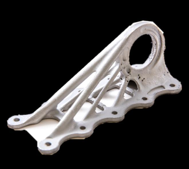
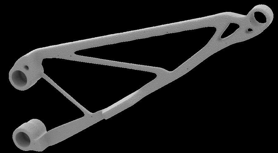
29 Validation on Real Parts With friendly support from Airbus Emerging Technologies & Concepts we have been allowed to use their bionic cabin bracket that is used in the Airbus A350 XWB for our tests. The original part is build by Concept Laser in Titanium CL 41TI ELI (TiAl6V4 ELI) with their additive LaserCUSING process. For our tests the parts were build in Aluminum at approx. half size. Bionic cabin bracket in Airbus A350 XWB built on M2 cusing / Material CL 41TI ELI (TiAl6V4 ELI) / Lightweight natural construction solutions can be generated almost 1:1 with the additive LaserCUSING process. The laser-generated component with an optimized structure delivers a weight saving of more than 30% compared with the component produced by conventional means!


30 Bionic Cabin Bracket Again we designed 6 different kind of brackets with statistically varying pore distributions or defects and provided the STL files to Concept Laser. Concept Laser printed 3 samples of each kind in CL 31 Aluminium. The parts have not been heattreated. All 18 samples have been CT scanned.

31 Bionic Cabin Bracket - Pull Test On all 18 samples a pull test was performed at k-labor GmbH.
 and the")
32 Bionic Cabin Bracket - Load Scenario We calculated simulations on all 18 samples CT-data sets. We used the same predefined load scenario as used in the experiment where the bracket is fixed to the ground plate by 10 bolts (red) and the application of force is under an angle of 29 into the ring (green).


33 Bionic Cabin Bracket - Results Here are the results: The excellent correlation results between experiment and simulation average of 3 Prediction data has been scaled by a uniform scaling factor.


34 Predicted Hotspots vs Actual Failure Position Sample 1.1 Prediction hotspot #1 Fractured in the ring


35 Predicted Hotspots vs Actual Failure Position Sample 3.2 Prediction hotspot #2 Fractured in the lower strut Fracture NDT in Canada 2018 June Halifax, NS


36 Predicted Hotspots vs Actual Failure Position Sample 5.2 Prediction hotspot #1 Fractured in the struts

37 Stress Analysis Tool Validation Can we trust in the calculated results? Yes we can!?????????


38 Structural Mechanical Simulation Our Stress Analysis module allows simulation of linear stress on single and multi-material objects. It supports three force types: Directed force Torque Pressure It calculates multiple stress plots directly on CT data, no meshing.


39 Volume Graphics VGSTUDIO MAX Structural Mechanical Simulation With the SMS module VG combines ease of use with other analysis types for the next level in digital inspection. The SMS module is available in VGSTUDIO MAX now.
40
Simulation of the Stress Concentration around Pores in 3D Printed Components
 Simulation of the Stress Concentration around Pores in 3D Printed Components K.-M. Nigge1, J. Fieres1, C. Reinhart1, P. Schumann2 1 2 Volume Graphics GmbH, Heidelberg, Germany Concept Laser GmbH, Lichtenfels,
VGSTUDIO MAX 3.0. High-End Industrial CT Software
 VGSTUDIO MAX 3.0 High-End Industrial CT Software VGSTUDIO MAX 3.0 High-End Software for CT Data VGSTUDIO MAX 3.0 is the high-end software for the visualization and analysis of industrial computed tomography
VGSTUDIO MAX. High-End Industrial CT Software
 VGSTUDIO MAX High-End Industrial CT Software VGSTUDIO MAX High-End Software for CT Data VGSTUDIO MAX is the high-end software for the analysis and visualization of industrial computed tomography (CT) data.
CT in Dimensional Metrology, Engineering and Manufacture
 CT in Production Quality Control - Leuven, June 4, 2013 CT in Dimensional Metrology, Engineering and Manufacture Prof. Dr. Ir. Jean-Pierre KRUTH Katholieke Universiteit Leuven (K.U.Leuven) Mechanical Engineering
Metal 3D Printing. - Design for Metal 3D Printing - 10th October 2018
 Metal 3D Printing - Design for Metal 3D Printing - 10th October 2018 Agenda 1. Short Introduction Materialise 2. Design for Manufacturing / M3DP 3. General Design Process 4. Topology Optimization 5. Example
Wieblinger Weg 92a, Heidelberg, Germany, Phone: , Fax: ;
 HOW INDUSTRIAL COMPUTER TOMOGRAPHY ACCELERATES PRODUCT DEVELOPMENT IN THE LIGHT METAL CASTING AND INJECTION MOULDING INDUSTRY. Christof REINHART 1, Christoph POLIWODA 1, Thomas GÜNTHER 1 1 Volume Graphics
LightHinge+: Additively manufactured lightweight hood hinge with integrated pedestrian protection
 LightHinge+: Additively manufactured lightweight hood hinge with integrated pedestrian protection Sebastian Flügel EDAG Engineering GmbH HANNOVER MESSE 26.04.2018 EDAG Engineering GmbH: Portfolio Folie
Closing the gap in the design to additive manufacturing chain by numerical tools
 Closing the gap in the design to additive manufacturing chain by numerical tools European Altair Technology Conference 26.06.2017 Frankenthal Nils Keller Additive Works GmbH Additive Works 2 Additive Works
VGSTUDIO MAX. High-End Industrial CT Software
 VGSTUDIO MAX High-End Industrial CT Software VGSTUDIO MAX High-End Software for the Analysis and Visualization of CT Data From design to serial production, VGSTUDIO MAX enables you to keep the quality
Japan Foundry Society, Inc. Application of Recent X-ray CT Technology to Investment Casting field. Kouichi Inagaki ICC / IHI Corporation
 Japan Foundry Society, Inc. Application of Recent X-ray CT Technology to Investment Casting field Kouichi Inagaki ICC / IHI Corporation 13 th WORLD CONFERENCE ON INVESTMENT CASTING Paper: T3 Copyright
Validation Report: Additional Data Mapping to Structural Analysis Packages
 Autodesk Moldflow Structural Alliance 2012 Validation Report: Additional Data Mapping to Structural Analysis Packages Mapping process-induced stress data from Autodesk Moldflow Insight Dual Domain and
NDT of a Composite Using MicroCT Data and Image-based Finite Element Modelling
 The Open Access NDT Database www.ndt.net/?id=10703 NDT of a Composite Using MicroCT Data and Image-based Finite Element Modelling Ross T. COTTON 1, Ali ABDUL-AZIZ 2, Philippe G. YOUNG 3 1 Simpleware Ltd.;
SIMULATION CAPABILITIES IN CREO
 SIMULATION CAPABILITIES IN CREO Enhance Your Product Design with Simulation & Using digital prototypes to understand how your designs perform in real-world conditions is vital to your product development
Example of 3D Injection Molding CAE Directly Connected with 3D CAD
 3D TIMON Example of 3D Injection Molding CAE Directly Connected with 3D CAD 1 Background Problem of Data Translation from 3D CAD to CAE 3D TIMON Difficulty to Generate mesh Automatically Topologically
Fiber Composite Material Analysis in Aerospace Using CT Data
 4th International Symposium on NDT in Aerospace 2012 - We.2.A.3 Fiber Composite Material Analysis in Aerospace Using CT Data Dr. Tobias DIERIG, Benjamin BECKER, Christof REINHART, Thomas GÜNTHER Volume
CHAPTER 3. METHODOLOGY. This chapter describes the background theory and different
 CHAPTER 3. METHODOLOGY This chapter describes the background theory and different methods of simulations, details on finite element analysis, different types of simulation used in the sand castings, the
Case Study- Importing As-Molded Plastic Part Conditions into CAE tools
 1 IEI Innova Engineering 1 Park Plaza Suite 980 Irvine, California 92614 Case Study- Importing As-Molded Plastic Part Conditions into CAE tools 2 CONTENTS CONTENTS... 2 EXECUTIVE SUMMARY... 3 APPROACH...
MCT225 HA Metrology CT
 MCT225 HA Metrology CT Absolute accuracy for inside metrology nikon metrology I vision beyond precision Today, manufacturers are seeking to reduce time-to-market, despite a greater variety of products
Robustness analysis of metal forming simulation state of the art in practice. Lectures. S. Wolff
 Lectures Robustness analysis of metal forming simulation state of the art in practice S. Wolff presented at the ICAFT-SFU 2015 Source: www.dynardo.de/en/library Robustness analysis of metal forming simulation
Engineering Effects of Boundary Conditions (Fixtures and Temperatures) J.E. Akin, Rice University, Mechanical Engineering
 J.E. Akin, Rice University, Mechanical Engineering") Engineering Effects of Boundary Conditions (Fixtures and Temperatures) J.E. Akin, Rice University, Mechanical Engineering Here SolidWorks stress simulation tutorials will be re-visited to show how they
Engineering Effects of Boundary Conditions (Fixtures and Temperatures) J.E. Akin, Rice University, Mechanical Engineering Here SolidWorks stress simulation tutorials will be re-visited to show how they
A new concept for high-speed atline and inline CT for up to 100% mass production process control allowing both 3D metrology and failure analysis
 A new concept for high-speed atline and inline CT for up to 100% mass production process control allowing both 3D metrology and failure analysis Oliver Brunke 1, Ferdinand Hansen 2, Ingo Stuke 3, Friedrich
A new Concept for High-Speed atline and inlinect for up to 100% Mass Production Process Control
 18th World Conference on Nondestructive Testing, 16-20 April 2012, Durban, South Africa A new Concept for High-Speed atline and inlinect for up to 100% Mass Production Process Control Oliver BRUNKE 1,
VGStudio MAX 3.0. High-End Industrial CT Software
 VGStudio MAX 3.0 High-End Industrial CT Software VGSTUDIO MAX 3.0 STATE OF THE ART FOR CT DATA VGStudio MAX 3.0 is the latest version of the high-end software for the visualization and analysis of industrial
FINITE ELEMENT MODELING OF THICK PLATE PENETRATIONS IN SMALL CAL MUNITIONS
 FINITE ELEMENT MODELING OF THICK PLATE PENETRATIONS IN SMALL CAL MUNITIONS Raymond Chaplin RDAR-MEM-I Picatinny Arsenal, NJ raymond.c.chaplin@us.army.mil 973-724-8562 Why Finite Element Modeling? Reduced
Revision of the SolidWorks Variable Pressure Simulation Tutorial J.E. Akin, Rice University, Mechanical Engineering. Introduction
 Revision of the SolidWorks Variable Pressure Simulation Tutorial J.E. Akin, Rice University, Mechanical Engineering Introduction A SolidWorks simulation tutorial is just intended to illustrate where to
A new Concept for High-Speed atline and inlinect for up to 100% Mass Production Process Control
 6 th International Congress of Metrology, 06003 (203) DOI: 0.05/ metrology/20306003 C Owned by the authors, published by EDP Sciences, 203 A new Concept for High-Speed atline and inlinect for up to 00%
CHAPTER 4. Numerical Models. descriptions of the boundary conditions, element types, validation, and the force
 CHAPTER 4 Numerical Models This chapter presents the development of numerical models for sandwich beams/plates subjected to four-point bending and the hydromat test system. Detailed descriptions of the
CAD - How Computer Can Aid Design?
 CAD - How Computer Can Aid Design? Automating Drawing Generation Creating an Accurate 3D Model to Better Represent the Design and Allowing Easy Design Improvements Evaluating How Good is the Design and
The part to be analyzed is the bracket from the tutorial of Chapter 3.
 Introduction to Solid Modeling Using SolidWorks 2007 COSMOSWorks Tutorial Page 1 In this tutorial, we will use the COSMOSWorks finite element analysis (FEA) program to analyze the response of a component
Stress analysis of Camshaft by using ANSYS Software
 Stress analysis of Camshaft by using ANSYS Software Samta Jain, Mr. Vikas Bansal Rajasthan Technical University, kota (Rajasathan), India Abstract This paper presents the modeling and static structural
PARAMETERS INFLUENCING THE PRECISION OF SLM PRODUCTION
 PARAMETERS INFLUENCING THE PRECISION OF SLM PRODUCTION PETR KELLER, RADOMIR MENDRICKY Department of Manufacturing Systems and Automation, Technical University of Liberec, Liberec, Czech Republic DOI: 10.17973/MMSJ.2015_10_201540
Identification of process phenomena in DMLS by optical inprocess
 Lasers in Manufacturing Conference 2015 Identification of process phenomena in DMLS by optical inprocess monitoring R. Domröse a, *, T. Grünberger b a EOS GmbH Electro Optical Systems, Robert-Stirling-Ring
Topology Optimization Requirements in the Age of Additive Manufacturing
 Topology Optimization Requirements in the Age of Additive Manufacturing Dr. Andreas Vlahinos Principal at Advanced Engineering Solutions andreas@aes.nu Topology Optimization Roundtable Hilton Crystal City
Revised Sheet Metal Simulation, J.E. Akin, Rice University
 Revised Sheet Metal Simulation, J.E. Akin, Rice University A SolidWorks simulation tutorial is just intended to illustrate where to find various icons that you would need in a real engineering analysis.
Advanced Material Models and Geomechanics
 Advanced Material Models and Geomechanics Giovanni Federico, Mark Robinson ANSYS UK Ltd 1 2016 ANSYS, Inc. April 28, 2017 2 2016 ANSYS, Inc. April 28, 2017 Advanced Material Models NEW Unified Viscoplasticity
AUTOMATED METHODOLOGY FOR MODELING CRACK EXTENSION IN FINITE ELEMENT MODELS
 AUTOMATED METHODOLOGY FOR MODELING CRACK THEME Structural Analysis - Durability, Fatigue & Fracture. James J. Kosloski Senior Engineering Manager - CAE Associates Dr. Michael Bak Senior Engineering Manager
SIMULATION CAPABILITIES IN CREO. Enhance Your Product Design with Simulation & Analysis
 SIMULATION CAPABILITIES IN CREO Enhance Your Product Design with Simulation & Using digital prototypes to understand how your designs perform in real-world conditions is vital to your product development
Advanced automated High Speed Computed Tomography for production process control. DGZfP 2011, Bremen
 DGZfP-Jahrestagung 2011 - Mo.3.B.3 Advanced automated High Speed Computed Tomography for production process control DGZfP 2011, Bremen Dr. Ingo Stuke* and Dr. Oliver Brunke** GE Sensing & Inspection Technologies
PTC Creo Simulate. Features and Specifications. Data Sheet
 PTC Creo Simulate PTC Creo Simulate gives designers and engineers the power to evaluate structural and thermal product performance on your digital model before resorting to costly, time-consuming physical
REPLICATING A CMM-BASED INSPECTION PROCESS. InnovMetric Software replicates a CMM-based inspection process using a 3D digitizer and PolyWorks
 PRATT & WHITNEY REPLICATING A CMM-BASED INSPECTION PROCESS InnovMetric Software replicates a CMM-based inspection process using a 3D digitizer and PolyWorks Today, manufacturers in the automotive and aerospace
INTEGRATED ANISOTROPIC SIMULATION FOR COMPONENTS MADE FROM GLASS FIBER REINFORCED THERMOPLASTICS
 INTEGRATED ANISOTROPIC SIMULATION FOR COMPONENTS MADE FROM GLASS FIBER REINFORCED THERMOPLASTICS David Sheridan Ticona, Auburn Hills, Michigan Ulrich Mohr-Matuschek & Anton Grzeschik Ticona, Sulzbach,
VGMETROLOGY. Maximum Precision, Minimal CT Data Set Sizes
 VGMETROLOGY Maximum Precision, Minimal CT Data Set Sizes Full-featured but nonetheless easy-to-use VGMETROLOGY is made for metrologists. The Universal Metrology Solution VGMETROLOGY is made for metrologists.
New Approach in Non- Contact 3D Free Form Scanning
 New Approach in Non- Contact 3D Free Form Scanning Contents Abstract Industry Trends The solution A smart laser scanning system Implementation of the laser scanning probe in parts inspection Conclusion
RAPID PROTOTYPING FOR SLING DESIGN OPTIMIZATION
 RAPID PROTOTYPING FOR SLING DESIGN OPTIMIZATION Zaimović-Uzunović, N. * ; Lemeš, S. ** ; Ćurić, D. *** ; Topčić, A. **** * University of Zenica, Fakultetska 1, 72000 Zenica, Bosnia and Herzegovina, nzaimovic@mf.unze.ba
The new generation of industrial computed tomography. The Desktop CT exact S
 The new generation of industrial computed tomography The Desktop CT S Volume scanning technology Innovation with a family tradition Founded in 1968, the family-owned, WEN- ZEL Metrology Group is one of
Analysis of low cycle fatigue considering geometric manufacturing tolerances
 presented at the 14th Weimar Optimization and Stochastic Days 2017 Source: www.dynardo.de/en/library Analysis of low cycle fatigue considering geometric manufacturing tolerances SIEMENS AG applies ANSYS,
Nouveautés ANSYS pour le calcul structurel et l impression 3D. CADFEM 2017 ANSYS Additive Manufacturing
 Titelmasterformat Journée Technologique durch AddiPole Klicken bearbeiten Nouveautés ANSYS pour le calcul structurel et l impression 3D Titelmasterformat Structural design with durch ANSYS Klicken bearbeiten
INDUSTRIAL SYSTEM DEVELOPMENT FOR VOLUMETRIC INTEGRITY
 INDUSTRIAL SYSTEM DEVELOPMENT FOR VOLUMETRIC INTEGRITY VERIFICATION AND ANALYSIS M. L. Hsiao and J. W. Eberhard CR&D General Electric Company Schenectady, NY 12301 J. B. Ross Aircraft Engine - QTC General
ANALYSIS AND OPTIMIZATION OF FLYWHEEL
 Int. J. Mech. Eng. & Rob. Res. 2012 Sushama G Bawane et al., 2012 Research Paper ISSN 2278 0149 www.ijmerr.com Vol. 1, No. 2, July 2012 2012 IJMERR. All Rights Reserved ANALYSIS AND OPTIMIZATION OF FLYWHEEL
NX Advanced FEM. fact sheet
 Advanced FEM fact sheet www.ugs.com Summary Advanced FEM is a comprehensive multi-cad finite element modeling and results visualization product that is designed to meet the needs of experienced CAE analysts.
DETECTION AND QUANTIFICATION OF CRACKS IN PRESSURE VESSELS USING ESPI AND FEA MODELLS
 DETECTION AND QUANTIFICATION OF CRACKS IN PRESSURE VESSELS USING ESPI AND FEA MODELLS J GRYZAGORIDIS, DM FINDEIS, JR MYLES Department of Mechanical Engineering University of Cape Town Abstract Non destructive
Finite Element Analysis Using Creo Simulate 4.0
 Introduction to Finite Element Analysis Using Creo Simulate 4.0 Randy H. Shih SDC PUBLICATIONS Better Textbooks. Lower Prices. www.sdcpublications.com Powered by TCPDF (www.tcpdf.org) Visit the following
CHAPTER 5 USE OF STL FILE FOR FINITE ELEMENT ANALYSIS
 CHAPTER 5 USE OF STL FILE FOR FINITE ELEMENT ANALYSIS 5.1 Introduction: Most CAD software in the market can generate STL files, and these are generally used for prototyping and rendering purposes. These
Stress analysis of toroidal shell
 Stress analysis of toroidal shell Cristian PURDEL*, Marcel STERE** *Corresponding author Department of Aerospace Structures INCAS - National Institute for Aerospace Research Elie Carafoli Bdul Iuliu Maniu
Computational Methodology for Optimal Design of Additive Layer Manufactured Turbine Bracket
 KES Transactions on Sustainable Design and Manufacturing I Sustainable Design and Manufacturing 2014 : pp.641-652 : Paper sdm14-037 Computational Methodology for Optimal Design of Additive Layer Manufactured
FEA and Topology Optimization of an Engine Mounting Bracket
 International Journal of Current Engineering and Technology E-ISSN 2277 4106, P-ISSN 2347 5161 2016 INPRESSCO, All Rights Reserved Available at http://inpressco.com/category/ijcet Research Article Sanket
Topology Optimization for Designers
 TM Topology Optimization for Designers Siemens AG 2016 Realize innovation. Topology Optimization for Designers Product Features Uses a different approach than traditional Topology Optimization solutions.
DARWIN 8.1 Release Notes
 DARWIN 8.1 Release Notes March 2015 Southwest Research Institute Summary of New Capabilities DARWIN 8.1 includes the following new features: Autozoning with inspection Random FE residual stress Anomaly
A Comparison of the Computational Speed of 3DSIM versus ANSYS Finite Element Analyses for Simulation of Thermal History in Metal Laser Sintering
 A Comparison of the Computational Speed of 3DSIM versus ANSYS Finite Element Analyses for Simulation of Thermal History in Metal Laser Sintering Kai Zeng a,b, Chong Teng a,b, Sally Xu b, Tim Sublette b,
Coordinate Measuring Machines with Computed Tomography
 Always a Step Ahead with Quality Coordinate Measuring Machines with Computed Tomography Multisensor Coordinate Measuring Machines with Computed Tomography Computed Tomography in Coordinate Measuring Machines
CHAPTER 4 INCREASING SPUR GEAR TOOTH STRENGTH BY PROFILE MODIFICATION
 68 CHAPTER 4 INCREASING SPUR GEAR TOOTH STRENGTH BY PROFILE MODIFICATION 4.1 INTRODUCTION There is a demand for the gears with higher load carrying capacity and increased fatigue life. Researchers in the
Analysis of Crank End of Connecting Rod using Finite Element Method
 Analysis of Crank End of Connecting Rod using Finite Element Method Mohammad Umair Zaki Faculty of Mechanical Engineering Noida International University Greater Noida, India e-mail-umairzaki@yahoo.com
Titanium Topology Optimized TiTO 3D Printed Satellite Panel Support System
 Titanium Topology Optimized TiTO 3D Printed Satellite Panel Support System White Paper By Precision ADM Abstract Precision ADM developed a TiTO (Titanium Topology Optimized) Aerospace Panel Support Structure.
Dr. Javier Santillan, San Carlos, CA
 X-ray diffraction as a tool for automated residual st ress analysis & a non-synchrotron based nanofocus x-ray computed tomography technique for materials characterization and metrology Dr. Javier Santillan,
Contents. 1 CoreTech System Co., Ltd.
 Contents Advanced Support for Intelligent Workflow Improved User Interface 2 Expanded Gate Types.. 2 Enhanced Runner Wizard. 2 Customized Cooling Channel Templates. 3 Parameterized Mesh Generator... 3
Coke Drum Laser Profiling
 International Workshop on SMART MATERIALS, STRUCTURES NDT in Canada 2013Conference & NDT for the Energy Industry October 7-10, 2013 Calgary, Alberta, CANADA Coke Drum Laser Profiling Mike Bazzi 1, Gilbert
Autodesk Moldflow Insight AMI Cool Analysis Products
 Autodesk Moldflow Insight 2012 AMI Cool Analysis Products Revision 1, 22 March 2012. This document contains Autodesk and third-party software license agreements/notices and/or additional terms and conditions
ixcube 4-10 Brief introduction for membrane and cable systems.
 ixcube 4-10 Brief introduction for membrane and cable systems. ixcube is the evolution of 20 years of R&D in the field of membrane structures so it takes a while to understand the basic features. You must
Advanced Non-Destructive Testing by High Resolution Computed Tomography for 3D analysis of Automotive Components
 Advanced Non-Destructive Testing by High Resolution Computed Tomography for 3D analysis of Automotive Components J. Luebbehuesen GE Sensing & Inspection Technologies GmbH, phoenix x-ray, Niels-Bohr-Str.
Design Workflow for AM: From CAD to Part
 Design Workflow for AM: From CAD to Part Sanjay Joshi Professor of Industrial and Manufacturing Engineering Penn State University Offered by: Center for Innovative Materials Processing through Direct Digital
Digital Laminography and Computed Tomography with 600 kv for Aerospace Applications
 4th International Symposium on NDT in Aerospace 2012 - Tu.3.A.1 Digital Laminography and Computed Tomography with 600 kv for Aerospace Applications Malte KURFISS 1, Gerd STRECKENBACH 2 1 YXLON International
Statistics on Structures 3.1
 New features exploring new fields of application Christian Bucher, Claudia Bucher, Christopher Riemel, Sebastian Wolff* DYNARDO Austria GmbH WOST 2014, 6./7.11.2014, Weimar optislang & SoS: What is the
Optiv CT160 Accurate measurement for every detail. Computed Tomography System
 Optiv CT160 Accurate measurement for every detail Computed Tomography System Computed Tomography CT Technology. New prospects for metrology. Computed tomography (CT), a technology with unique advantages,
Image courtesy of Local Motors Inc.
 Image courtesy of Local Motors Inc. Image courtesy of Local Motors Inc. Advanced Materials and Manufacturing Advanced Materials and Manufacturing The promise of advanced materials and manufacturing
Simpleware: Converting 3D Images into Computational Models. David Harman (Application Engineer)
") Simpleware: Converting 3D Images into Computational Models David Harman (Application Engineer) d.harman@simpleware.com Introduction Simpleware: The Company Developers of industry-leading software solutions
Simpleware: Converting 3D Images into Computational Models David Harman (Application Engineer) d.harman@simpleware.com Introduction Simpleware: The Company Developers of industry-leading software solutions
Topology Optimization of Flaring Tool Using OptiStruct
 Topology Optimization of Flaring Tool Using OptiStruct Rahul Nanche Engineer CAE Emerson Innovation Center Hinjewadi,Pune 411057 Sachin Magdum Lead Engineer Emerson Innovation Center Hinjewadi,Pune 411057
Structural re-design of engine components
 Structural re-design of engine components Product design cycle Design Development Testing Structural optimization Product knowledge Design freedom 2/18 Structural re-design of engine components Product
Artificial Neural Network Based Geometric Compensation for Thermal Deformation in Additive Manufacturing Processes
 Artificial Neural Network Based Geometric Compensation for Thermal Deformation in Additive Manufacturing Processes A Thesis submitted to the Graduate School of the University of Cincinnati In partial fulfillment
International Journal of Mechanical Civil and Control Engineering. Vol. 1, Issue. 3, June 2015 ISSN (Online):
:") Design Evolution of a Typical Aircraft Engine Mount Bracket Using FE Based Optimisation Technique Revanasidda Benur 1 and Akshatha H T 2 1 former project trainee, 2 Senior Scientist, Centre for Civil Aircraft
Design Evolution of a Typical Aircraft Engine Mount Bracket Using FE Based Optimisation Technique Revanasidda Benur 1 and Akshatha H T 2 1 former project trainee, 2 Senior Scientist, Centre for Civil Aircraft
NX Advanced FEM. Benefits
 Advanced FEM fact sheet Siemens PLM Software www.siemens.com/plm Summary Advanced FEM software is a comprehensive multi-cad finite element modeling and results visualization product that is designed to
Modelling Flat Spring Performance Using FEA
 Modelling Flat Spring Performance Using FEA Blessing O Fatola, Patrick Keogh and Ben Hicks Department of Mechanical Engineering, University of Corresponding author bf223@bath.ac.uk Abstract. This paper
Integrated FEM-based. package for Fatigue and Damage Tolerance - SAFE
 Integrated FEM-based package for Fatigue and Damage Tolerance - SAFE Emmanuelle ALIOS Jean-Pascal KLEINERMANN 1 Content Introduction Airbus France tool : SAFE General overview Assessment of initiation
Finite Element Method using Pro/ENGINEER and ANSYS
 Finite Element Method using Pro/ENGINEER and ANSYS Notes by R.W. Toogood The transfer of a model from Pro/ENGINEER to ANSYS will be demonstrated here for a simple solid model. Model idealizations such
Optimization and Simulation of Machining Parameters in Radial-axial Ring Rolling Process
 International Journal of Computational Intelligence Systems, Vol.4, No. 3 (May, 0). Optimization and Simulation of Machining Parameters in Radial-axial Ring Rolling Process Shuiyuan Tang, Jiping Lu *,
Materials Modelling and Interoperability Siemens PLM Vision
 Materials Modelling and Interoperability Siemens PLM Vision November 2017 Realize innovation. Siemens PLM Simulation & Test Solutions Mission: Help end user industry to manufacture better products more
Sharif University of Technology. Session # Rapid Prototyping
 Advanced Manufacturing Laboratory Department of Industrial Engineering Sharif University of Technology Session # Rapid Prototyping Contents: Rapid prototyping and manufacturing RP primitives Application
Application of CAD/CAE/CAM Technology in Plastics Injection Mould Design and Manufacture. Ming He Dai,Zhi Dong Yun
 Advanced Materials Research Vols. 399-401 (2012) pp 2271-2275 Online available since 2011/Nov/22 at www.scientific.net (2012) Trans Tech Publications, Switzerland doi:10.4028/www.scientific.net/amr.399-401.2271
Introduction. File preparation
 White Paper Design and printing guidelines Introduction A print job can be created in either of the following ways: NOTE: HP SmartStream 3D Build Manager supports STL and 3MF files. By using the HP SmartStream
The CAE- Driven Mechanical Design Process
 The CAE- Driven Mechanical Design Process A graduate- level mechanical engineering course inspired by Inspire Mark JAKIELA Hunter Professor of Mechanical Design Washington University in St. Louis Syllabus
Exercise 2: Mesh Resolution, Element Shapes, Basis Functions & Convergence Analyses
 Exercise 2: Mesh Resolution, Element Shapes, Basis Functions & Convergence Analyses Goals In this exercise, we will explore the strengths and weaknesses of different element types (tetrahedrons vs. hexahedrons,
Autodesk Moldflow Adviser. Design plastics confidently.
 Autodesk Moldflow Adviser Design plastics confidently. Design Plastic Parts and Injection Molds with Confidence Discover, communicate, and resolve potential manufacturing defects earlier in the product
Available online at ScienceDirect. Procedia Engineering 183 (2017 )
") Available online at www.sciencedirect.com ScienceDirect Procedia Engineering 183 (2017 ) 369 374 17th International Conference on Sheet Metal, SHEMET17 Reverse analysis of scan strategies for controlled
Available online at www.sciencedirect.com ScienceDirect Procedia Engineering 183 (2017 ) 369 374 17th International Conference on Sheet Metal, SHEMET17 Reverse analysis of scan strategies for controlled
HP-L-8.9 LASER SCANNER
 PRODUCT BROCHURE HP-L-8.9 LASER SCANNER Cost-effective laser scanning for the ROMER Absolute Arm 2 HP-L-8.9 LASER SCANNER HIGHLIGHTS MAKING LASER SCANNING ACCESSIBLE TO ALL The HP-L-8.9 is an affordable
APPROACHING A RELIABLE PROCESS SIMULATION FOR THE VIRTUAL PRODUCT DEVELOPMENT
 APPROACHING A RELIABLE PROCESS SIMULATION FOR THE VIRTUAL PRODUCT DEVELOPMENT K. Kose, B. Rietman, D. Tikhomirov, N. Bessert INPRO GmbH, Berlin, Germany Summary In this paper an outline for a strategy
X-rays see all X-ray computed microtomography (µct) a novel technique available at CERN for material and metrological inspection
 a novel technique available at CERN for material and metrological inspection") X-rays see all X-ray computed microtomography (µct) a novel technique available at CERN for material and metrological inspection Mariusz Jedrychowski EN/MME-MM Introduction of new technique at CERN 12/12/2017
X-rays see all X-ray computed microtomography (µct) a novel technique available at CERN for material and metrological inspection Mariusz Jedrychowski EN/MME-MM Introduction of new technique at CERN 12/12/2017
An Overview of Computer Aided Design and Finite Element Analysis
 An Overview of Computer Aided Design and Finite Element Analysis by James Doane, PhD, PE Contents 1.0 Course Overview... 4 2.0 General Concepts... 4 2.1 What is Computer Aided Design... 4 2.1.1 2D verses
Exercise 1. 3-Point Bending Using the Static Structural Module of. Ansys Workbench 14.0
 Exercise 1 3-Point Bending Using the Static Structural Module of Contents Ansys Workbench 14.0 Learn how to...1 Given...2 Questions...2 Taking advantage of symmetries...2 A. Getting started...3 A.1 Choose
DESIGN & ANALYSIS OF CONNECTING ROD OF FORMING AND CUTTING DIE PILLAR STATION OF VACUUM FORMING MACHINE
 Research Paper ISSN 2278 0149 www.ijmerr.com Vol. 3, No. 3, July, 2014 2014 IJMERR. All Rights Reserved DESIGN & ANALYSIS OF CONNECTING ROD OF FORMING AND CUTTING DIE PILLAR STATION OF VACUUM FORMING MACHINE
US foundry Bradken implements optical measuring technology
 Application Note US foundry Bradken implements optical measuring technology Location / country: Tacoma / Washington, USA GOM systems: ATOS Triple Scan, TRITOP GOM software: ATOS Professional Sector: Power
CREO AND DESIGN FOR ADDITIVE MANUFACTURING
 CREO AND DESIGN FOR ADDITIVE MANUFACTURING Jose Coronado Lara Director, Creo manufacturing solutions November, 2018 CREO 5.0 ADDITIVE MANUFACTURING 2 AGENDA AM Drives Digital Transformation Lightweight