AdequateReconstructionofTransparentObjectsonaShoestringBudget
|
|
|
- Henry Sydney Copeland
- 6 years ago
- Views:
Transcription

1 AdequateReconstructionofTransparentObjectsonaShoestringBudget Sai-Kit Yeung 1,2 Tai-Pang Wu 2 Chi-Keung Tang 2 Tony F. Chan 1,2 Stanley Osher 1 saikit@math.ucla.edu pang@cse.ust.hk cktang@cse.ust.hk tonyfchan@ust.hk sjo@math.ucla.edu 1 University of California, Los Angeles 2 The Hong Kong University of Science and Technology Abstract Reconstructing transparent objects is a challenging problem. While producing reasonable results for quite complex objects, existing approaches require custom calibration or somewhat expensive labor to achieve high precision. On the other hand, when an overall shape preserving salient andfinedetailsissufficient,weshowinthispaperasignificant step toward solving the problem on a shoestring budget, by using only a video camera, a moving spotlight, and a small chrome sphere. Specifically, the problem we addressistoestimatethenormalmapoftheexteriorsurface of a given solid transparent object, from which the surface depth can be integrated. Our technical contribution lies in relating this normal reconstruction problem to one of graph-cut segmentation. Unlike conventional formulations, however, our graph is dual-layered, since we can see a transparent object s foreground as well as the background behind it. Quantitative and qualitative evaluation are performed to verify the efficacy of this practical solution. 1. Introduction We address the problem of normal reconstruction for a transparent object, where the integrated surface is an overall shape of the target object that preserves salient features and fine structures if present on its exterior surface. Such detail-preserving exterior surface representation is adequate for vision and robotics applications where transparent objects are to be grabbed by a robotic arm, or avoided by a navigating robot in a cluttered scene. In our paper, our goal is different from photorealistic rendering or high-accuracy reconstruction of transparent objects, where custom equipment, calibrated and mechanical capture are often deemed necessary to achieve precision as high as to trace the complex refractive light-transport paths exhibited by the target object. On the other hand, when an adequate shape without The research was partially supported by the Hong Kong Research Grant Council under grant number 62009, RICE/MURI Award SN-80050, NSF TH and ONR N Figure 1. Six images showing a typical input (example FISH). Most pixels do not record highlight in these images, indicating a sparse set of images is inadequate for applying orientation consistency. this level of precision is sufficient, it is possible to propose a reconstruction approach that uses a simpler setup realizable using a smaller budget. Without expensive or complicated setup while still supporting an adequate reconstruction, what visual cues concerning a transparent object can be utilized? Although some of us have had the unpleasant experience of smacking into a glass window without seeing it, we can still see a wide range of transparent objects despite their apparent transparency, because most of them refract and reflect incoming light. Tracing refractive light-transport paths using calibrated setup and capture had contributed to the success of techniques aiming at high-precision reconstruction. This paper on the other hand makes use of specularities directly reflected off an transparent object to produce an adequate reconstruction. Due to the low dynamic range of our inexpensive video camera, however, indirect reflection caused by complex light transport (e.g., caustics and total internal reflection) also produces strong highlights with intensity that appears as strong as direct specular highlights. Thus, the main problem to be solved is to identify at each pixel the subset of collected highlights that are caused by direct specular reflection Technical Overview The working principle of our system is: given dense lighting directions, a pixel location within the data capture range has a high probability to observe a specular highlight directly reflected off the surface point being observed, see Figure 1. This can be used to obtain the surface normal from a specular object with known reference geometry. At first glance, given a dense collection of highlights at a pixel, 1

2 Figure 2. Our budget setup. The spotlight is moved around to simulate a distant light source with constant radiance. The video camera is an off-the-shelf DV of limited dynamic range. The transparent object and the reference chrome sphere are captured at the same time. direct application of orientation consistency similarly done in photometric stereo by examples [5] (where in our case each pixel receives a normal transferred from a known geometry) in a winner-takes-all or thresholded setting [2] for normal recovery would have solved our reconstruction problem. But, this problem proves to be challenging, as our low-cost capture device (Figure 2), which is similar to [2], is an off-the-shelf DV camera of limited dynamic range, where highlights caused by direct or indirect reflections are likely be recorded with equally high intensities. To make the problem tractable, we propose to use normal cues given by shape-from-silhouette, and sparse normal cues marked on a single view for tracking true and rejecting false highlights. The technical contribution consists of the optimal integration of these two normal cues for deriving the target normal map. It turns out that the optimization problem can be mapped into one similar to image segmentation and thus formulated into a graph-cut optimization. Our graph, on the other hand, is different from those in conventional graph-cut formulation: it is a dual-layered graph because we can observe a transparent object s foreground as well as the background behind it Paper s Structure The organization of the rest of the paper is as follows: Section 2 reviews related work. Section describes the observations and assumptions used in our approach. Section 4 describes the normal map estimation using graph-cuts. Section 5 presents the results. Finally, we conclude our paper in section Related Work The following classical works determine the shape of a transparent object by specularities. In specular stereo [1] a two-camera configuration and image trajectory were used. A theory of specular surface was developed in [16], where the relationship between specular surface geometry and image trajectories were studied and features were classified as real and virtual. Virtual features, which are reflections by a specular surface not limited to highlights, contain useful information on the shape of the object. In [11], two views were used to model the surface of a transparent object, by making use of the optical phenomenon that the degree of polarization of the light reflected from the object surface depends on the reflection angle, which in turn depends on surface normal. This approach utilizing light polarization, where the light transport paths were ray-traced, was further explored in [10] where one camera was used. In [8], a theory was developed on refractive and specular D shape by studying the light transport paths, which are restricted to undergo no more than two refractions. Two views were used for dynamic refraction stereo [12] where the notion of refractive disparity was introduced. In this work, a reference pattern and refractive liquid were used. Scatter trace photography [1] was then proposed to reconstruct transparent objects made of inhomogeneous materials, by using a well-calibrated capture device to distinguish direct scatter trace from other indirect optical observations. In [6], a transparent object was immersed into fluorescent liquid. Computer-controlled laser projector and multiview scans were available for merging. While the recovered normal maps of mesostructures look good in [2] and were demonstrated to be useful for relighting, their assumption on specular highlight does not apply to general transparent objects that exhibit complex refraction phenomena (such as total internal reflection and caustics). Our shape reconstruction method makes use of rough initial shape (normals), sparse normal cues, and dense specular highlights, which sets itself apart from the above approaches where mathematical theories were developed based on the physics of light transport, or simplifying assumptions were imposed on the transparent object.. Observations and Assumptions Given a dense set of views of a solid transparent object captured by a static video camera under variable illumination, the problem is to reconstruct the normal map by utilizing specular highlights directly reflected off the surface. The specular highlight directly reflected corresponds to the observed normals of the exterior surface, after applying orientation consistency using a reference shape of known geometry, which is a chrome sphere in our case. Transparent objects are more challenging, since indirect reflections caused by complex light transport and caustics can also produce highlight as strong as direct specular reflection. Using our inexpensive capture system and under the orthographic camera assumption, we have the following key observations: Data capture range. The light direction is restricted such that those falling outside the 90-degree realm will be ignored; otherwise the light source would have been located


3 (a) Figure. (a) Orientation consistency in the presence of transparency and indirect illumination effects. The reference sphere and the object have different material properties but they act like ideal specular objects when they reflect specular highlights (brightness and contrast were enhanced for visualization). Under the orthographic camera assumption, we can directly obtain the normal orientation from the reference sphere. Notice that given a single view, only a subset of normals can be computed. (L is light direction, R reflection direction, N is normal direction.) (a) direct indirect, strong (c) indirect, weak Figure 4. [color figure] Three typical scenarios on the observed light emanating from a point on the exterior surface of a transparent and refractive object. The numbers in the figure indicate intensity magnitudes. (a) Nearly ideal specular reflection. In practice, the specular highlight spans a finite region in the image. Non-specular reflection where the intensity is similar to that of a true specular highlight. Examples include caustics and total internal reflection reflected off from the back surface of the object. (c) Non-specular reflection where the intensity is attenuated making it easily discarded by thresholding. Orientation consistency should be applied to (a), but not to or (c) because they are not specular reflections. behind the transparent object. Under this lighting configuration and using a shiny chrome sphere (Figure (a)) as a reference geometry, surface normals falling outside the 45- degree realm measured from the upward direction cannot be recovered, Figure. The mathematical explanation can be readily derived using the law of specular reflection under orthographic projection. Highlight appearance. Direct specular highlight is bright and concentrated (Figure 4(a)). However, some nonspecular indirect reflection observed will also be classified as highlight. It happens when caustics and total internal reflection behind the surface appear as bright as specular reflection, especially a low-dynamic-range digital video camera is used in image capture (Figure 4). Obvious true or false highlights can be marked up by user for disambiguation if needed. Data availability. Given the limited data capture range, some pixels will have no highlight, or the observed intensity is not high enough to be considered a highlight (Figure 4(c)). Normal clusters. The normals transferred from the chrome sphere after applying orientation consistency will form distinctive clusters at a pixel over the time frames (Figure 5), one of which corresponds to direct specular highlights whereas the rest are due to indirect illumination. In all of our experiments, we found that a pixel location observes at most two salient normals clusters over all the frames captured. A third cluster, if it exists, is too weak to be detected as highlight. This two-cluster observation, however, is not critical: as long as the strongest is detected or identified as direct specular highlight, the exact number of clusters does not matter.
![frame 984 frame 1681 Normal clusters correspond to the same pixel Pixel to be considered frame 98 frame 1682 Figure 5. [color figure] The normal clusters at a particular pixel over time. 4.](/docs-images/80/81489223/images/4-1.jpg "Normal Optimization We propose to solve the optimization problem by integrating the rough shape given by an object s silhouette, and the normals transferred via orientation consistency.")

4 frame 984 frame 1681 Normal clusters correspond to the same pixel Pixel to be considered frame 98 frame 1682 Figure 5. [color figure] The normal clusters at a particular pixel over time. 4. Normal Optimization We propose to solve the optimization problem by integrating the rough shape given by an object s silhouette, and the normals transferred via orientation consistency. To resolve severe highlight ambiguity as stated in the previous section, a limited amount of user specification is employed. This improves not only the initialization but also the optimization process. The optimization can be mapped to one similar to image segmentation and solved via graph-cut optimization Initialization Since an object s silhouette on an image is easily available, a rough overall shape can be derived from shape from silhouette. Normals derived from the resulting shape give a reasonable initial guess. To improve the quality of initial normals, the user may indicate true highlights on keyframes. Automatic tracking technique is applied to trace the corresponding locations inbetween frames. With the true highlights being tracked, we can transfer the normals from a chrome sphere, and these normals are considered as hard constraints in shape-fromsilhouette for computing the initial rough shape. Given a sparse set of normals, consisting of transferred normals obtained from user s markups and the silhouette normals, we compute the surface normal n F for all pixels within the object s silhouette via a standard MRF formuation for which a stable implementation is available [14] Shape Refinement by Graph Cuts After estimating initial normals, the next step is to integrate the information given by the dense highlight collected. As discussed in previous section, given a total of T image frames, the possible situations at a given pixel are: 1) no highlight, 2) highlights form a single normal cluster, ) highlights form two or more normal clusters. So our problem is translated into a labeling problem, that is, given a normal cluster, determine if it corresponds to one that produces direct specular reflection on the exterior surface. Our idea is to utilize the data measurement given by applying orientation consistency to refine the initial surface. The initial shape also gives us relevant cues for rejecting wrong measurements due to false highlights. Normal clustering. The shape optimization problem can be posed as a binary labeling problem, by assigning every cluster as exterior surface normal or otherwise. Since each pixel can observe direct and indirect reflections, we adopt the following method to extract the two representative normals: Given T observations per pixel, we threshold the pixel intensities to discard weak intensities. It results in M usable observations, where 0 M T. If M = 0, it means that this pixel contains no useful information and initial normal will be used instead. Otherwise, we apply K- means clustering to extract all normal clusters. The process with K = 2 is illustrated in Figure 6(a). Using Minimum Description Length principle [4, ] the value of K can be estimated automatically. Graph formulation. Next, we construct a graph G = V, E, where V is the set of all nodes and E is the set of all edges connecting adjacent nodes. In our case, the nodes contain labels to the two most salient normals clustered, and the edges represent adjacency relationships. The graph can have up to 2N nodes for N processing pixels and every node can have 9 edges as shown in Figure 6. For pixel locations with only one cluster, we duplicate the cluster in the other node to simplify the implementation (Figure 6(c)). The labeling problem is to assign a unique label s i for each node i V, i.e., s i {exterior surface normal (= 1), otherwise (= 0)}. The solution S = {s i } corresponding to the final frontal surface normals can be obtained by minimizing a Gibbs energy E(S) [9]: E(S) = E 1 (s i ) + E 2 (s i, s j ) (1) i V {i,j} E where E 1 (s i ) is the likelihood energy, denoting the cost
5 1 2 4 T T 2 T 1 T Contribute to clusters Frequency Mean 1 Mean 2 y x Cluster 1 Cluster 2 Orientation (a) (c) Figure 6. (a) For every pixel location, we cluster the transferred normals into two salient clusters given the T image frames. A duallayered graph G = V, E is built where each pixel has a green node and a blue node. V is the set of all nodes representing the clustered normals, E is the set of all edges connecting adjacent nodes. (c) For pixels with only one cluster, one can duplicate the cluster to simplify the implementation. The final graph can have up to 2N nodes for N processing pixels. Every node can have up to 9 edges connected to their neighboring nodes. Pixel locations with no observation will be completed by their initial estimation. NORMAL IMAGE OPTIMIZATION SEGMENTATION Labels Exterior/ Foreground/ Interior Background Nodes Clustered normals Pixels Processing token Gradients Colors Table 1. Analogy of our problem to image segmentation (e.g., [17, 9]). when the label of node i is s i, and E 2 (s i, s j ) is the prior energy, encoding the cost when the labels of adjacent nodes i and j are s i and s j respectively. Our problem becomes a graph-cut energy minimization problem [7] and is very similar to the image segmentation problem using graph cuts [17, 9]. An analogy of our problem to image segmentation is shown in Table 1. The main difference with segmentation is that our graph is dual-layered as shown in Figure 6, since the exterior and non-exterior surface(s) can be observed at the same time as the object is transparent. Likelihoodenergyandcounternormal. In Eqn (1), E 1 encodes at each node the normal similarity between the clustered normal observed from the collected highlights and the initial normal. However, simply using the initial normals from silhouette is not adequate to encode E 1, since the information on the non-exterior surface should also be considered. This is analogous to image segmentation where color cues from foreground and background should be available for processing. We introduce the idea of counter normal which is a normal dissimilar to the initial normal, in order to define the affinity and hence the energy of assigning an observed normal to non-exterior surface. The idea is as follows: If an observed normal n i does not belong to the exterior surface, it will not be similar to the initial normal n F i. In other words, we may say n i is similar to a normal that isdissimilar to the initial normal. Let us call it counter normal. Since our captured normals must be facing upward, it is meaningless to consider normals with n z < 0. Therefore, we set the corresponding counter normal by flipping the gradient of n F i, i.e. {p C i, qc i } = { pf i, qf i }, where pc i and qc i are the x and y gradient of n C i, and pf i and qi F are the x and y gradient of n F i. Basically, this strategy adopts the most dissimilar surface normal (with z-axis as the reference) with upward direction as the counter normal. With the initial normal and the counter normal, we can now define our energy term E 1. For each node i, we compute the difference of the corresponding gradients with the frontal gradient and the counter (non-frontal) gradient by d F i = p i p F i + q i qi F and dc i = p i p C i + q i qi C respectively. Notice that for pixel locations with no highlight observation, we set the labels of two nodes at each of these pixels to correspond to the initial p F i values and set E 1 (0) = E 2 (0) = 0.5 so the smoothness term takes over in the optimal labeling problem. Therefore, E 1 (s i ) can be defined as following: E 1 (s i = 1) = 0 E 1 (s i = 0) = i F E 1 (s i = 1) = E 1 (s i = 0) = 0 i C E 1 (s i = 1) = df i d F i + E 1 (s i = 0) = dc i dc i d F i + i U 1 dc i E 1 (s i = 1) = 0.5 E 1 (s i = 0) = 0.5 i U 2(2) where U 1 and U 2 are the set of nodes from region with and without normal observation, respectively, and {U 1 U 2 } = V {F C} is the set of uncertain nodes to be labeled. Eqn (2) is similar to [9] except for i U 2. F is the set of nodes labeled as exterior surface normals, which are available in the initialization. C is the set of nodes corresponding to non-exterior normal observations, which are specified by the user in a similar manner as the exterior surface normals,
 Lambertian-shaded Normal map from [2] and integrated surface. (d) (e) Our normal map and surface. e.g., by marking up false instead of true highlights.")

, minimizing the energy E1 produces a winner-takes-all labeling strategy based on normal similarity only.")
 = si sj g(")


 in Eqn (1).")


 (d) (e) Figure 8. J UG. The top shows eight captured images.")
![The bottom shows the recovered normal maps N, displayed as N L with L = ( 1, 1, 1 )T. (a) Normal map by [2]. Normal map by [15].](/docs-images/80/81489223/images/6-10.jpg "(c) Normal map using our method. (d) and (e) compare the reconstructed surfaces from our normal maps with the real object.")
![shown exclude those of surface integration, where we use the source codes from [14] to produce the final surfaces. Setup.](/docs-images/80/81489223/images/6-11.jpg "To capture a dense image set, similar in fashion to [5, 2], we use an off-the-shelf DV camera with a fixed viewpoint to simultaneously")

. They can be served as the ground truth for quantitative comparison.")


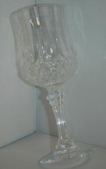
6 (a) (a) (c) (d) (e) Figure 7. Objects with known geometry (S PHERE and C YLIN DER ) for quantitative evaluation. (a) Photo of the object. (c) Lambertian-shaded Normal map from [2] and integrated surface. (d) (e) Our normal map and surface. e.g., by marking up false instead of true highlights. Notice that since our graph is dual-layered, nodes in F and C can have the same pixel location. This is the main difference in the graph construction as compared to works in image segmentation [17, 9] where nodes in F and C must have different locations. The first two equations guarantee the nodes in F or C always have the label consistent with user inputs. If we ignore the E2 term in Eqn (1), minimizing the energy E1 produces a winner-takes-all labeling strategy based on normal similarity only. Prior energy. We use E2 to encode the smoothness constraint between neighboring nodes. Define the normal similarity function between two nodes i and j as an inverse function of the smoothness constraint: E2 (si, sj ) = si sj g( pi pj + qi qj ) () where g(ξ) = (ξ + 1) 1. Note that si sj allows us to capture the smoothness information when the adjacent nodes have different labels. In other words, E2 is a penalty term when neighboring nodes are assigned with different labels. So if the neighboring normals are similar, assigning them with different labels will increase the energy of the graph and vice versa. This energy term encourages integrable normals to be grouped into the same surface. We use the max-flow algorithm [7] to minimize the energy E(S) in Eqn (1). Readers may notice that we do not enforce the two nodes at the same pixel location (recall our graph is dual-layered) to have different labels in our graph formulation. Although in our examples, pixel originally having two clusters will always have one labeled as exterior surface normal, we cannot guarantee that the two clusters may both come from false highlights. 5. Experimental Results The data sets tested and running times of normal map reconstruction are summarized in Table 2. The running times (c) (d) (e) Figure 8. J UG. The top shows eight captured images. The bottom shows the recovered normal maps N, displayed as N L with L = ( 1, 1, 1 )T. (a) Normal map by [2]. Normal map by [15]. (c) Normal map using our method. (d) and (e) compare the reconstructed surfaces from our normal maps with the real object. shown exclude those of surface integration, where we use the source codes from [14] to produce the final surfaces. Setup. To capture a dense image set, similar in fashion to [5, 2], we use an off-the-shelf DV camera with a fixed viewpoint to simultaneously capture the reference chrome sphere and the target object. A moving spotlight is used to mimic a distant light source at varying directions. Quantitative Evaluation. In order to evaluate the performance of our system, we capture two real data sets whose analytical geometries are known (namely, a hemisphere and a cylinder). They can be served as the ground truth for quantitative comparison. We compute the average difference of our computed surface normals with S PHERE and C YLINDER respectively. The results are depicted in Table. We also generate the surface normals by using a winnertakes-all strategy such as [2]. We implemented this strategy as the sum of second order moments followed by eigendecomposition. The corresponding visual results are shown in Figure 7. From the results, we can see that our final reconstructed shape is more faithful compared with the one using the winner-takes-all strategy. Without proper labeling, the normals from the true highlight will be mixed up with the wrong normals transferred due to false highlights, making the final optimized normals fail to integrate into a reasonable surface as shown in Figure 7(c). Qualitative Evaluation. Figure 8 shows the single-view reconstruction result on a transparent glass J UG. This example is simple as the initial shape is already close to the final solution. We show one view of the surface reconstruction alongside with the real object in a similar view. Figure 9 shows the results a glass figurine F ISH, which is very similar to the one used in [1] and our result looks comparable. Note that the image sequence contains a lot of shadows and highlight. The figurine contains internal structures of varied colors. However, it is highly specular and thus can produce sufficient specular observations. The zoom-in views illustrate the details preserved in our recon-

![106 [2] 0.78 0.768 0.86 0.406 Table.](/docs-images/80/81489223/images/7-2.jpg "The mean errors of the computed surface normals using our method and [2] are shown (where the error is defined as sum of the squared difference of three normal components).")
 (c) L = ( 1 1, 1, ) T, (d) L = (0, 0,1) T, (e) L = ( 1, shows the reconstructed surface. 1, 1 ) T.")
![The middle row (a) winner-takes-all strategy [2]. user-supplied normal cues and silhouettes [15]. (c) Our result in frontal view. (d) (e) Our results in other views.](/docs-images/80/81489223/images/7-4.jpg "The bottom shows the comparison of the reconstructed surface with the real object at similar viewpoint. (h) Zoom-in view of (f). (i) Zoom-in view of (g).")


7 no. of images image dimensions total running time (sec) SPHERE CYLINDER JUG FISH WINE GLASS WATER GLASS Table 2. Running times are measured on a desktop computer with Dual-Core 2.6 GHz CPU and.0 GB RAM. SPHERE CYLINDER data region whole region data region whole region Our method [2] Table. The mean errors of the computed surface normals using our method and [2] are shown (where the error is defined as sum of the squared difference of three normal components). Data region consists of pixel locations with highlight observations. Whole region includes all processing pixels. (a) (c) (d) (e) (f) (g) (h) (i) Figure 9. FISH. The top shows thenormalmaps N displayed as N L. The lighting directions are: (a) (c) L = ( 1 1, 1, ) T, (d) L = (0, 0,1) T, (e) L = ( 1, shows the reconstructed surface. 1, 1 ) T. The middle row (a) winner-takes-all strategy [2]. user-supplied normal cues and silhouettes [15]. (c) Our result in frontal view. (d) (e) Our results in other views. The bottom shows the comparison of the reconstructed surface with the real object at similar viewpoint. (h) Zoom-in view of (f). (i) Zoom-in view of (g). The figurine is a solid transparent object with complex colors inside the object. struction of the object s exterior surface. Although there are some errors due to shadows, overall the surface reconstruction result is quite robust to the complex color, texture and internal structure. The initial shape-from-silhouette in lacks the level of details in comparison with our final surface result shown in (c) and other views in the figure. We tested our approach using two complex transparent objects WATER GLASS and WINE GLASS. Figure 10 shows the reconstruction result on a transparent WATER GLASS which has a complex shape. The result is acceptable in regions where salient highlights can be detected. Note the faithfulness of the recovered shape using our approach where true highlights are picked and false ones are suppressed. Figure 11 shows another result on a transparent WINE GLASS where a lot of orientation discontinuities are present. Note in the normal map the fine details of the wine glass preserved. Two views of the reconstructed surface, alongside with the real object in similar views are shown. Note that a similar glass was also used in fluorescent immersion range scanning [6]. Our surface generated using our shoestring budget looks reasonable and comparable in many ways. 6. Conclusion and Future Work This paper presents a practical approach for reconstructing the normal map of the exterior surface of a transparent object. While inadequate for high-precision graphics rendering, our detail-preserving output is a faithful reconstruction of the transparent object, as demonstrated by our convincing results, and should be useful in a range of vision applications. Our approach makes use of an initial shape, normals transferred using orientation consistencies, and sparse user markups if needed. The problem was translated into one similar to image segmentation, and the optimization can be formulated using graph cuts on a duallayered graph. This alternative approach is desirable for quick D prototyping of existing transparent objects with details adequately preserved. Our current system produces a depth map for the exterior surface of a transparent object. To generate a full D reconstruction, it is possible to merge overlapping depth maps which will be the future work.
 (h) (e) (i) Figure 11.")


 (c) L = ( 1,")
T.")
![(a) winner-takes-all strategy [2].](/docs-images/80/81489223/images/8-6.jpg "user-supplied normal cues and")
![silhouettes [15].](/docs-images/80/81489223/images/8-7.jpg "(c)-(e) our results.")


![zoom-in views. References [1] A.](/docs-images/80/81489223/images/8-10.jpg "Blake and G. Brelstaff.")

![[2] T. Chen, M. Goesele, and H.-P.](/docs-images/80/81489223/images/8-12.jpg "Seidel.")
, pages 1825 182, 2006.")
![[] R. M. Gray.](/docs-images/80/81489223/images/8-14.jpg "Entropy and Information Theory.")


![[5] A. Hertzmann and S. Seitz.](/docs-images/80/81489223/images/8-17.jpg "Example-based photometric stereo:")


8 (a) (c) (d) (e) (a) (f) (c) (g) (d) (h) (e) (i) Figure 11. W INE G LASS. See Figure 10 caption. (f) (g) (h) (i) Figure 10. WATER G LASS. The top shows ten captured input images and normal maps N displayed as N L: The lighting directions respectively are: (a) (c) L = ( 1, 1, 1 )T, (d) L = (0, 0, 1)T, (e) L = ( 1, 1, 1 )T. (a) winner-takes-all strategy [2]. user-supplied normal cues and silhouettes [15]. (c)-(e) our results. (f) (i) show the comparison of our reconstructed surfaces with the real object at novel viewpoints, alongsize with the corresponding zoom-in views. References [1] A. Blake and G. Brelstaff. Specular stereo. In IJCAI85, pages , [2] T. Chen, M. Goesele, and H.-P. Seidel. Mesostructure from specularity. In CVPR (2), pages , [] R. M. Gray. Entropy and Information Theory. SpringerVerlag, November [4] P. Grunwarld. Minimum Description Length and Maximum Probability. Kluwer, [5] A. Hertzmann and S. Seitz. Example-based photometric stereo: Shape reconstruction with general, varying brdfs. PAMI, 27(8): , August [6] M. B. Hullin, M. Fuchs, I. Ihrke, H.-P. Seidel, and H. P. A. Lensch. Fluorescent immersion range scanning. ACM Transactions on Graphics, 27():87:1 87:10, Aug [7] V. Kolmogorov and R. Zabih. What energy functions can be minimized via graph cuts? PAMI, 26(2): , February [8] K. Kutulakos and E. Steger. A theory of refractive and specular d shape by light-path triangulation. In ICCV05, pages II: , [9] Y. Li, J. Sun, C.-K. Tang, and H.-Y. Shum. Lazy snapping. ACM Trans. Graph., 2():0 08, [10] D. Miyazaki and K. Ikeuchi. Shape estimation of transparent objects by using inverse polarization ray tracing. PAMI, 29(11): , November [11] D. Miyazaki, M. Kagesawa, and K. Ikeuchi. Transparent surface modeling from a pair of polarization images. PAMI, 26(1):7 82, January [12] N. Morris and K. Kutulakos. Dynamic refraction stereo. In ICCV05, pages II: , [1] N. Morris and K. Kutulakos. Reconstructing the surface of inhomogeneous transparent scenes by scatter trace photography. In ICCV07, [14] H.-S. Ng, T.-P. Wu, and C.-K. Tang. Surface-from-gradients without discrete integrability enforcement: A gaussian kernel approach. IEEE Trans. Pattern Anal. Mach. Intell., 2(11): , [15] Y. Ohtake, A. G. Belyaev, and H.-P. Seidel. Ridge-valley lines on meshes via implicit surface fitting. ACM Trans. Graph., 2(): , [16] M. Oren and S. Nayar. A theory of specular surface geometry. IJCV, 24(2): , September [17] C. Rother, V. Kolmogorov, and A. Blake. GrabCut : interactive foreground extraction using iterated graph cuts. ACM Trans. Graph., 2():09 14, 2004.
Normal Estimation of a Transparent Object Using a Video
 890 IEEE TRANSACTIONS ON PATTERN ANALYSIS AND MACHINE INTELLIGENCE, VOL. 7, NO. 4, APRIL 2015 Normal Estimation of a Transparent Object Using a Video Sai-Kit Yeung, Tai-Pang Wu, Chi-Keung Tang, Tony F.
Prof. Trevor Darrell Lecture 18: Multiview and Photometric Stereo
 C280, Computer Vision Prof. Trevor Darrell trevor@eecs.berkeley.edu Lecture 18: Multiview and Photometric Stereo Today Multiview stereo revisited Shape from large image collections Voxel Coloring Digital
Rendering and Modeling of Transparent Objects. Minglun Gong Dept. of CS, Memorial Univ.
 Rendering and Modeling of Transparent Objects Minglun Gong Dept. of CS, Memorial Univ. Capture transparent object appearance Using frequency based environmental matting Reduce number of input images needed
What have we leaned so far?
 What have we leaned so far? Camera structure Eye structure Project 1: High Dynamic Range Imaging What have we learned so far? Image Filtering Image Warping Camera Projection Model Project 2: Panoramic
A Survey of Light Source Detection Methods
 A Survey of Light Source Detection Methods Nathan Funk University of Alberta Mini-Project for CMPUT 603 November 30, 2003 Abstract This paper provides an overview of the most prominent techniques for light
Light source estimation using feature points from specular highlights and cast shadows
 Vol. 11(13), pp. 168-177, 16 July, 2016 DOI: 10.5897/IJPS2015.4274 Article Number: F492B6D59616 ISSN 1992-1950 Copyright 2016 Author(s) retain the copyright of this article http://www.academicjournals.org/ijps
Multi-view Stereo. Ivo Boyadzhiev CS7670: September 13, 2011
 Multi-view Stereo Ivo Boyadzhiev CS7670: September 13, 2011 What is stereo vision? Generic problem formulation: given several images of the same object or scene, compute a representation of its 3D shape
Learning and Inferring Depth from Monocular Images. Jiyan Pan April 1, 2009
 Learning and Inferring Depth from Monocular Images Jiyan Pan April 1, 2009 Traditional ways of inferring depth Binocular disparity Structure from motion Defocus Given a single monocular image, how to infer
Rendering: Reality. Eye acts as pinhole camera. Photons from light hit objects
 Basic Ray Tracing Rendering: Reality Eye acts as pinhole camera Photons from light hit objects Rendering: Reality Eye acts as pinhole camera Photons from light hit objects Rendering: Reality Eye acts as
Specular Reflection Separation using Dark Channel Prior
 2013 IEEE Conference on Computer Vision and Pattern Recognition Specular Reflection Separation using Dark Channel Prior Hyeongwoo Kim KAIST hyeongwoo.kim@kaist.ac.kr Hailin Jin Adobe Research hljin@adobe.com
L2 Data Acquisition. Mechanical measurement (CMM) Structured light Range images Shape from shading Other methods
 Structured light Range images Shape from shading Other methods") L2 Data Acquisition Mechanical measurement (CMM) Structured light Range images Shape from shading Other methods 1 Coordinate Measurement Machine Touch based Slow Sparse Data Complex planning Accurate 2
L2 Data Acquisition Mechanical measurement (CMM) Structured light Range images Shape from shading Other methods 1 Coordinate Measurement Machine Touch based Slow Sparse Data Complex planning Accurate 2
CS6670: Computer Vision
 CS6670: Computer Vision Noah Snavely Lecture 20: Light, reflectance and photometric stereo Light by Ted Adelson Readings Szeliski, 2.2, 2.3.2 Light by Ted Adelson Readings Szeliski, 2.2, 2.3.2 Properties
Data-driven Depth Inference from a Single Still Image
 Data-driven Depth Inference from a Single Still Image Kyunghee Kim Computer Science Department Stanford University kyunghee.kim@stanford.edu Abstract Given an indoor image, how to recover its depth information
Local Illumination. CMPT 361 Introduction to Computer Graphics Torsten Möller. Machiraju/Zhang/Möller
 Local Illumination CMPT 361 Introduction to Computer Graphics Torsten Möller Graphics Pipeline Hardware Modelling Transform Visibility Illumination + Shading Perception, Interaction Color Texture/ Realism
Other approaches to obtaining 3D structure
 Other approaches to obtaining 3D structure Active stereo with structured light Project structured light patterns onto the object simplifies the correspondence problem Allows us to use only one camera camera
Visible Surface Reconstruction from Normals with Discontinuity Consideration
 Visible Surface Reconstruction from Normals with Discontinuity Consideration Tai-Pang Wu and Chi-Keung Tang Vision and Graphics Group The Hong Kong University of Science and Technology Clear Water Bay,
Fundamentals of Stereo Vision Michael Bleyer LVA Stereo Vision
 Fundamentals of Stereo Vision Michael Bleyer LVA Stereo Vision What Happened Last Time? Human 3D perception (3D cinema) Computational stereo Intuitive explanation of what is meant by disparity Stereo matching
Accurate 3D Face and Body Modeling from a Single Fixed Kinect
 Accurate 3D Face and Body Modeling from a Single Fixed Kinect Ruizhe Wang*, Matthias Hernandez*, Jongmoo Choi, Gérard Medioni Computer Vision Lab, IRIS University of Southern California Abstract In this
Multi-view stereo. Many slides adapted from S. Seitz
 Multi-view stereo Many slides adapted from S. Seitz Beyond two-view stereo The third eye can be used for verification Multiple-baseline stereo Pick a reference image, and slide the corresponding window
Multi-View 3D Reconstruction of Highly-Specular Objects
 Multi-View 3D Reconstruction of Highly-Specular Objects Master Thesis Author: Aljoša Ošep Mentor: Michael Weinmann Motivation Goal: faithful reconstruction of full 3D shape of an object Current techniques:
Comment on Numerical shape from shading and occluding boundaries
 Artificial Intelligence 59 (1993) 89-94 Elsevier 89 ARTINT 1001 Comment on Numerical shape from shading and occluding boundaries K. Ikeuchi School of Compurer Science. Carnegie Mellon dniversity. Pirrsburgh.
BIL Computer Vision Apr 16, 2014
 BIL 719 - Computer Vision Apr 16, 2014 Binocular Stereo (cont d.), Structure from Motion Aykut Erdem Dept. of Computer Engineering Hacettepe University Slide credit: S. Lazebnik Basic stereo matching algorithm
Passive 3D Photography
 SIGGRAPH 99 Course on 3D Photography Passive 3D Photography Steve Seitz Carnegie Mellon University http:// ://www.cs.cmu.edu/~seitz Talk Outline. Visual Cues 2. Classical Vision Algorithms 3. State of
ShapePalettes: Interactive Normal Transfer via Sketching
 ShapePalettes: Interactive Normal Transfer via Sketching Tai-Pang Wu The Hong Kong University of Science and Technology Chi-Keung Tang The Hong Kong University of Science and Technology Michael S. Brown
CS4670/5760: Computer Vision Kavita Bala Scott Wehrwein. Lecture 23: Photometric Stereo
 CS4670/5760: Computer Vision Kavita Bala Scott Wehrwein Lecture 23: Photometric Stereo Announcements PA3 Artifact due tonight PA3 Demos Thursday Signups close at 4:30 today No lecture on Friday Last Time:
Multiple View Geometry
 Multiple View Geometry Martin Quinn with a lot of slides stolen from Steve Seitz and Jianbo Shi 15-463: Computational Photography Alexei Efros, CMU, Fall 2007 Our Goal The Plenoptic Function P(θ,φ,λ,t,V
Lecture 15: Shading-I. CITS3003 Graphics & Animation
 Lecture 15: Shading-I CITS3003 Graphics & Animation E. Angel and D. Shreiner: Interactive Computer Graphics 6E Addison-Wesley 2012 Objectives Learn that with appropriate shading so objects appear as threedimensional
Efficient Photometric Stereo on Glossy Surfaces with Wide Specular Lobes
 Efficient Photometric Stereo on Glossy Surfaces with Wide Specular Lobes Hin-Shun Chung Jiaya Jia Department of Computer Science and Engineering The Chinese University of Hong Kong {hschung,leojia}@cse.cuhk.edu.hk
Lights, Surfaces, and Cameras. Light sources emit photons Surfaces reflect & absorb photons Cameras measure photons
 Reflectance 1 Lights, Surfaces, and Cameras Light sources emit photons Surfaces reflect & absorb photons Cameras measure photons 2 Light at Surfaces Many effects when light strikes a surface -- could be:
A Fixed Viewpoint Approach for Dense Reconstruction of Transparent Objects
 A Fixed Viewpoint Approach for Dense Reconstruction of Transparent Objects Kai Han, Kwan-Yee K. Wong, Miaomiao Liu The University of Hong Kong, Hong Kong, NICTA and CECS, ANU, Canberra {khan, kykwong}@cs.hku.hk,
Image Based Reconstruction II
 Image Based Reconstruction II Qixing Huang Feb. 2 th 2017 Slide Credit: Yasutaka Furukawa Image-Based Geometry Reconstruction Pipeline Last Lecture: Multi-View SFM Multi-View SFM This Lecture: Multi-View
Ligh%ng and Reflectance
 Ligh%ng and Reflectance 2 3 4 Ligh%ng Ligh%ng can have a big effect on how an object looks. Modeling the effect of ligh%ng can be used for: Recogni%on par%cularly face recogni%on Shape reconstruc%on Mo%on
CS 4495/7495 Computer Vision Frank Dellaert, Fall 07. Dense Stereo Some Slides by Forsyth & Ponce, Jim Rehg, Sing Bing Kang
 CS 4495/7495 Computer Vision Frank Dellaert, Fall 07 Dense Stereo Some Slides by Forsyth & Ponce, Jim Rehg, Sing Bing Kang Etymology Stereo comes from the Greek word for solid (στερεο), and the term can
3D object recognition used by team robotto
 3D object recognition used by team robotto Workshop Juliane Hoebel February 1, 2016 Faculty of Computer Science, Otto-von-Guericke University Magdeburg Content 1. Introduction 2. Depth sensor 3. 3D object
Dense 3D Reconstruction. Christiano Gava
 Dense 3D Reconstruction Christiano Gava christiano.gava@dfki.de Outline Previous lecture: structure and motion II Structure and motion loop Triangulation Today: dense 3D reconstruction The matching problem
CS6670: Computer Vision
 CS6670: Computer Vision Noah Snavely Lecture 21: Light, reflectance and photometric stereo Announcements Final projects Midterm reports due November 24 (next Tuesday) by 11:59pm (upload to CMS) State the
Perceptual Grouping from Motion Cues Using Tensor Voting
 Perceptual Grouping from Motion Cues Using Tensor Voting 1. Research Team Project Leader: Graduate Students: Prof. Gérard Medioni, Computer Science Mircea Nicolescu, Changki Min 2. Statement of Project
Stereo Vision. MAN-522 Computer Vision
 Stereo Vision MAN-522 Computer Vision What is the goal of stereo vision? The recovery of the 3D structure of a scene using two or more images of the 3D scene, each acquired from a different viewpoint in
Structured Light II. Thanks to Ronen Gvili, Szymon Rusinkiewicz and Maks Ovsjanikov
 Structured Light II Johannes Köhler Johannes.koehler@dfki.de Thanks to Ronen Gvili, Szymon Rusinkiewicz and Maks Ovsjanikov Introduction Previous lecture: Structured Light I Active Scanning Camera/emitter
CS 4495 Computer Vision A. Bobick. Motion and Optic Flow. Stereo Matching
 Stereo Matching Fundamental matrix Let p be a point in left image, p in right image l l Epipolar relation p maps to epipolar line l p maps to epipolar line l p p Epipolar mapping described by a 3x3 matrix
Colour Segmentation-based Computation of Dense Optical Flow with Application to Video Object Segmentation
 ÖGAI Journal 24/1 11 Colour Segmentation-based Computation of Dense Optical Flow with Application to Video Object Segmentation Michael Bleyer, Margrit Gelautz, Christoph Rhemann Vienna University of Technology
Project 2 due today Project 3 out today. Readings Szeliski, Chapter 10 (through 10.5)
") Announcements Stereo Project 2 due today Project 3 out today Single image stereogram, by Niklas Een Readings Szeliski, Chapter 10 (through 10.5) Public Library, Stereoscopic Looking Room, Chicago, by Phillips,
Announcements Stereo Project 2 due today Project 3 out today Single image stereogram, by Niklas Een Readings Szeliski, Chapter 10 (through 10.5) Public Library, Stereoscopic Looking Room, Chicago, by Phillips,
Variational Multiframe Stereo in the Presence of Specular Reflections
 Variational Multiframe Stereo in the Presence of Specular Reflections Hailin Jin Anthony J. Yezzi Stefano Soatto Electrical Engineering, Washington University, Saint Louis, MO 6330 Electrical and Computer
Computer Graphics. Illumination and Shading
 () Illumination and Shading Dr. Ayman Eldeib Lighting So given a 3-D triangle and a 3-D viewpoint, we can set the right pixels But what color should those pixels be? If we re attempting to create a realistic
Chaplin, Modern Times, 1936
 Chaplin, Modern Times, 1936 [A Bucket of Water and a Glass Matte: Special Effects in Modern Times; bonus feature on The Criterion Collection set] Multi-view geometry problems Structure: Given projections
Understanding Variability
 Understanding Variability Why so different? Light and Optics Pinhole camera model Perspective projection Thin lens model Fundamental equation Distortion: spherical & chromatic aberration, radial distortion
Image Segmentation Using Iterated Graph Cuts Based on Multi-scale Smoothing
 Image Segmentation Using Iterated Graph Cuts Based on Multi-scale Smoothing Tomoyuki Nagahashi 1, Hironobu Fujiyoshi 1, and Takeo Kanade 2 1 Dept. of Computer Science, Chubu University. Matsumoto 1200,
Ping Tan. Simon Fraser University
 Ping Tan Simon Fraser University Photos vs. Videos (live photos) A good photo tells a story Stories are better told in videos Videos in the Mobile Era (mobile & share) More videos are captured by mobile
Nonrigid Surface Modelling. and Fast Recovery. Department of Computer Science and Engineering. Committee: Prof. Leo J. Jia and Prof. K. H.
 Nonrigid Surface Modelling and Fast Recovery Zhu Jianke Supervisor: Prof. Michael R. Lyu Committee: Prof. Leo J. Jia and Prof. K. H. Wong Department of Computer Science and Engineering May 11, 2007 1 2
Capturing light. Source: A. Efros
 Capturing light Source: A. Efros Review Pinhole projection models What are vanishing points and vanishing lines? What is orthographic projection? How can we approximate orthographic projection? Lenses
3D Shape and Indirect Appearance By Structured Light Transport
 3D Shape and Indirect Appearance By Structured Light Transport CVPR 2014 - Best paper honorable mention Matthew O Toole, John Mather, Kiriakos N. Kutulakos Department of Computer Science University of
arxiv: v1 [cs.cv] 28 Sep 2018
![arxiv: v1 [cs.cv] 28 Sep 2018](/thumbs/93/113542646.jpg "arxiv: v1 [cs.cv] 28 Sep 2018") Camera Pose Estimation from Sequence of Calibrated Images arxiv:1809.11066v1 [cs.cv] 28 Sep 2018 Jacek Komorowski 1 and Przemyslaw Rokita 2 1 Maria Curie-Sklodowska University, Institute of Computer Science,
Camera Pose Estimation from Sequence of Calibrated Images arxiv:1809.11066v1 [cs.cv] 28 Sep 2018 Jacek Komorowski 1 and Przemyslaw Rokita 2 1 Maria Curie-Sklodowska University, Institute of Computer Science,
Applying Synthetic Images to Learning Grasping Orientation from Single Monocular Images
 Applying Synthetic Images to Learning Grasping Orientation from Single Monocular Images 1 Introduction - Steve Chuang and Eric Shan - Determining object orientation in images is a well-established topic
Supervised texture detection in images
 Supervised texture detection in images Branislav Mičušík and Allan Hanbury Pattern Recognition and Image Processing Group, Institute of Computer Aided Automation, Vienna University of Technology Favoritenstraße
A Low Power, High Throughput, Fully Event-Based Stereo System: Supplementary Documentation
 A Low Power, High Throughput, Fully Event-Based Stereo System: Supplementary Documentation Alexander Andreopoulos, Hirak J. Kashyap, Tapan K. Nayak, Arnon Amir, Myron D. Flickner IBM Research March 25,
Highlight detection with application to sweet pepper localization
 Ref: C0168 Highlight detection with application to sweet pepper localization Rotem Mairon and Ohad Ben-Shahar, the interdisciplinary Computational Vision Laboratory (icvl), Computer Science Dept., Ben-Gurion
Announcements. Stereo Vision Wrapup & Intro Recognition
 Announcements Stereo Vision Wrapup & Intro Introduction to Computer Vision CSE 152 Lecture 17 HW3 due date postpone to Thursday HW4 to posted by Thursday, due next Friday. Order of material we ll first
3D Computer Vision. Structured Light II. Prof. Didier Stricker. Kaiserlautern University.
 3D Computer Vision Structured Light II Prof. Didier Stricker Kaiserlautern University http://ags.cs.uni-kl.de/ DFKI Deutsches Forschungszentrum für Künstliche Intelligenz http://av.dfki.de 1 Introduction
Tri-modal Human Body Segmentation
 Tri-modal Human Body Segmentation Master of Science Thesis Cristina Palmero Cantariño Advisor: Sergio Escalera Guerrero February 6, 2014 Outline 1 Introduction 2 Tri-modal dataset 3 Proposed baseline 4
Lighting. Figure 10.1
 We have learned to build three-dimensional graphical models and to display them. However, if you render one of our models, you might be disappointed to see images that look flat and thus fail to show the
Chapter 26 Geometrical Optics
 Chapter 26 Geometrical Optics 26.1 The Reflection of Light 26.2 Forming Images With a Plane Mirror 26.3 Spherical Mirrors 26.4 Ray Tracing and the Mirror Equation 26.5 The Refraction of Light 26.6 Ray
Extracting Smooth and Transparent Layers from a Single Image
 Extracting Smooth and Transparent Layers from a Single Image Sai-Kit Yeung Tai-Pang Wu Chi-Keung Tang saikit@ust.hk pang@ust.hk cktang@cse.ust.hk Vision and Graphics Group The Hong Kong University of Science
Lecture 10: Multi view geometry
 Lecture 10: Multi view geometry Professor Fei Fei Li Stanford Vision Lab 1 What we will learn today? Stereo vision Correspondence problem (Problem Set 2 (Q3)) Active stereo vision systems Structure from
Chapter 7. Conclusions and Future Work
 Chapter 7 Conclusions and Future Work In this dissertation, we have presented a new way of analyzing a basic building block in computer graphics rendering algorithms the computational interaction between
Photometric Stereo with Auto-Radiometric Calibration
 Photometric Stereo with Auto-Radiometric Calibration Wiennat Mongkulmann Takahiro Okabe Yoichi Sato Institute of Industrial Science, The University of Tokyo {wiennat,takahiro,ysato} @iis.u-tokyo.ac.jp
Analysis of photometric factors based on photometric linearization
 3326 J. Opt. Soc. Am. A/ Vol. 24, No. 10/ October 2007 Mukaigawa et al. Analysis of photometric factors based on photometric linearization Yasuhiro Mukaigawa, 1, * Yasunori Ishii, 2 and Takeshi Shakunaga
Specular 3D Object Tracking by View Generative Learning
 Specular 3D Object Tracking by View Generative Learning Yukiko Shinozuka, Francois de Sorbier and Hideo Saito Keio University 3-14-1 Hiyoshi, Kohoku-ku 223-8522 Yokohama, Japan shinozuka@hvrl.ics.keio.ac.jp
Detecting motion by means of 2D and 3D information
 Detecting motion by means of 2D and 3D information Federico Tombari Stefano Mattoccia Luigi Di Stefano Fabio Tonelli Department of Electronics Computer Science and Systems (DEIS) Viale Risorgimento 2,
DIFFUSE-SPECULAR SEPARATION OF MULTI-VIEW IMAGES UNDER VARYING ILLUMINATION. Department of Artificial Intelligence Kyushu Institute of Technology
 DIFFUSE-SPECULAR SEPARATION OF MULTI-VIEW IMAGES UNDER VARYING ILLUMINATION Kouki Takechi Takahiro Okabe Department of Artificial Intelligence Kyushu Institute of Technology ABSTRACT Separating diffuse
Dense 3D Reconstruction. Christiano Gava
 Dense 3D Reconstruction Christiano Gava christiano.gava@dfki.de Outline Previous lecture: structure and motion II Structure and motion loop Triangulation Wide baseline matching (SIFT) Today: dense 3D reconstruction
CMSC427 Shading Intro. Credit: slides from Dr. Zwicker
 CMSC427 Shading Intro Credit: slides from Dr. Zwicker 2 Today Shading Introduction Radiometry & BRDFs Local shading models Light sources Shading strategies Shading Compute interaction of light with surfaces
Multi-View 3D-Reconstruction
 Multi-View 3D-Reconstruction Cedric Cagniart Computer Aided Medical Procedures (CAMP) Technische Universität München, Germany 1 Problem Statement Given several calibrated views of an object... can we automatically
Segmentation Based Stereo. Michael Bleyer LVA Stereo Vision
 Segmentation Based Stereo Michael Bleyer LVA Stereo Vision What happened last time? Once again, we have looked at our energy function: E ( D) = m( p, dp) + p I < p, q > We have investigated the matching
Irradiance Gradients. Media & Occlusions
 Irradiance Gradients in the Presence of Media & Occlusions Wojciech Jarosz in collaboration with Matthias Zwicker and Henrik Wann Jensen University of California, San Diego June 23, 2008 Wojciech Jarosz
Logical Templates for Feature Extraction in Fingerprint Images
 Logical Templates for Feature Extraction in Fingerprint Images Bir Bhanu, Michael Boshra and Xuejun Tan Center for Research in Intelligent Systems University of Califomia, Riverside, CA 9252 1, USA Email:
A Feature Point Matching Based Approach for Video Objects Segmentation
 A Feature Point Matching Based Approach for Video Objects Segmentation Yan Zhang, Zhong Zhou, Wei Wu State Key Laboratory of Virtual Reality Technology and Systems, Beijing, P.R. China School of Computer
On-line and Off-line 3D Reconstruction for Crisis Management Applications
 On-line and Off-line 3D Reconstruction for Crisis Management Applications Geert De Cubber Royal Military Academy, Department of Mechanical Engineering (MSTA) Av. de la Renaissance 30, 1000 Brussels geert.de.cubber@rma.ac.be
Volume Illumination, Contouring
 Volume Illumination, Contouring Computer Animation and Visualisation Lecture 0 tkomura@inf.ed.ac.uk Institute for Perception, Action & Behaviour School of Informatics Contouring Scaler Data Overview -
Homework 4 Computer Vision CS 4731, Fall 2011 Due Date: Nov. 15, 2011 Total Points: 40
 Homework 4 Computer Vision CS 4731, Fall 2011 Due Date: Nov. 15, 2011 Total Points: 40 Note 1: Both the analytical problems and the programming assignments are due at the beginning of class on Nov 15,
Global Illumination CS334. Daniel G. Aliaga Department of Computer Science Purdue University
 Global Illumination CS334 Daniel G. Aliaga Department of Computer Science Purdue University Recall: Lighting and Shading Light sources Point light Models an omnidirectional light source (e.g., a bulb)
CS5670: Computer Vision
 CS5670: Computer Vision Noah Snavely Light & Perception Announcements Quiz on Tuesday Project 3 code due Monday, April 17, by 11:59pm artifact due Wednesday, April 19, by 11:59pm Can we determine shape
Segmentation and Tracking of Partial Planar Templates
 Segmentation and Tracking of Partial Planar Templates Abdelsalam Masoud William Hoff Colorado School of Mines Colorado School of Mines Golden, CO 800 Golden, CO 800 amasoud@mines.edu whoff@mines.edu Abstract
Other Reconstruction Techniques
 Other Reconstruction Techniques Ruigang Yang CS 684 CS 684 Spring 2004 1 Taxonomy of Range Sensing From Brain Curless, SIGGRAPH 00 Lecture notes CS 684 Spring 2004 2 Taxonomy of Range Scanning (cont.)
Deformable Mesh Model for Complex Multi-Object 3D Motion Estimation from Multi-Viewpoint Video
 Deformable Mesh Model for Complex Multi-Object 3D Motion Estimation from Multi-Viewpoint Video Shohei NOBUHARA Takashi MATSUYAMA Graduate School of Informatics, Kyoto University Sakyo, Kyoto, 606-8501,
Introduction to Computer Vision. Week 8, Fall 2010 Instructor: Prof. Ko Nishino
 Introduction to Computer Vision Week 8, Fall 2010 Instructor: Prof. Ko Nishino Midterm Project 2 without radial distortion correction with radial distortion correction Light Light Light! How do you recover
A Statistical Consistency Check for the Space Carving Algorithm.
 A Statistical Consistency Check for the Space Carving Algorithm. A. Broadhurst and R. Cipolla Dept. of Engineering, Univ. of Cambridge, Cambridge, CB2 1PZ aeb29 cipolla @eng.cam.ac.uk Abstract This paper
Image Resizing Based on Gradient Vector Flow Analysis
 Image Resizing Based on Gradient Vector Flow Analysis Sebastiano Battiato battiato@dmi.unict.it Giovanni Puglisi puglisi@dmi.unict.it Giovanni Maria Farinella gfarinellao@dmi.unict.it Daniele Ravì rav@dmi.unict.it
Overview of Active Vision Techniques
 SIGGRAPH 99 Course on 3D Photography Overview of Active Vision Techniques Brian Curless University of Washington Overview Introduction Active vision techniques Imaging radar Triangulation Moire Active
Multiview Stereo COSC450. Lecture 8
 Multiview Stereo COSC450 Lecture 8 Stereo Vision So Far Stereo and epipolar geometry Fundamental matrix captures geometry 8-point algorithm Essential matrix with calibrated cameras 5-point algorithm Intersect
Computational Imaging for Self-Driving Vehicles
 CVPR 2018 Computational Imaging for Self-Driving Vehicles Jan Kautz--------Ramesh Raskar--------Achuta Kadambi--------Guy Satat Computational Imaging for Self-Driving Vehicles Jan Kautz--------Ramesh Raskar--------Achuta
CS 4495 Computer Vision Motion and Optic Flow
 CS 4495 Computer Vision Aaron Bobick School of Interactive Computing Administrivia PS4 is out, due Sunday Oct 27 th. All relevant lectures posted Details about Problem Set: You may *not* use built in Harris
An Intuitive Explanation of Fourier Theory
 An Intuitive Explanation of Fourier Theory Steven Lehar slehar@cns.bu.edu Fourier theory is pretty complicated mathematically. But there are some beautifully simple holistic concepts behind Fourier theory
Lecture 17: Recursive Ray Tracing. Where is the way where light dwelleth? Job 38:19
 Lecture 17: Recursive Ray Tracing Where is the way where light dwelleth? Job 38:19 1. Raster Graphics Typical graphics terminals today are raster displays. A raster display renders a picture scan line
Today. Global illumination. Shading. Interactive applications. Rendering pipeline. Computergrafik. Shading Introduction Local shading models
 Computergrafik Matthias Zwicker Universität Bern Herbst 2009 Today Introduction Local shading models Light sources strategies Compute interaction of light with surfaces Requires simulation of physics Global
CS 4495 Computer Vision A. Bobick. Motion and Optic Flow. Stereo Matching
 Stereo Matching Fundamental matrix Let p be a point in left image, p in right image l l Epipolar relation p maps to epipolar line l p maps to epipolar line l p p Epipolar mapping described by a 3x3 matrix
CHAPTER 6 MODIFIED FUZZY TECHNIQUES BASED IMAGE SEGMENTATION
 CHAPTER 6 MODIFIED FUZZY TECHNIQUES BASED IMAGE SEGMENTATION 6.1 INTRODUCTION Fuzzy logic based computational techniques are becoming increasingly important in the medical image analysis arena. The significant
STRUCTURAL EDGE LEARNING FOR 3-D RECONSTRUCTION FROM A SINGLE STILL IMAGE. Nan Hu. Stanford University Electrical Engineering
 STRUCTURAL EDGE LEARNING FOR 3-D RECONSTRUCTION FROM A SINGLE STILL IMAGE Nan Hu Stanford University Electrical Engineering nanhu@stanford.edu ABSTRACT Learning 3-D scene structure from a single still
Path Tracing part 2. Steve Rotenberg CSE168: Rendering Algorithms UCSD, Spring 2017
 Path Tracing part 2 Steve Rotenberg CSE168: Rendering Algorithms UCSD, Spring 2017 Monte Carlo Integration Monte Carlo Integration The rendering (& radiance) equation is an infinitely recursive integral
Hybrid Textons: Modeling Surfaces with Reflectance and Geometry
 Hybrid Textons: Modeling Surfaces with Reflectance and Geometry Jing Wang and Kristin J. Dana Electrical and Computer Engineering Department Rutgers University Piscataway, NJ, USA {jingwang,kdana}@caip.rutgers.edu
Introduction to 3D Concepts
 PART I Introduction to 3D Concepts Chapter 1 Scene... 3 Chapter 2 Rendering: OpenGL (OGL) and Adobe Ray Tracer (ART)...19 1 CHAPTER 1 Scene s0010 1.1. The 3D Scene p0010 A typical 3D scene has several