SCIA stands for scientific analyser. The C in SCIA Engineering is not pronounced. Note that the first c in science is not pronounced either.
|
|
|
- Alice Cook
- 5 years ago
- Views:
Transcription


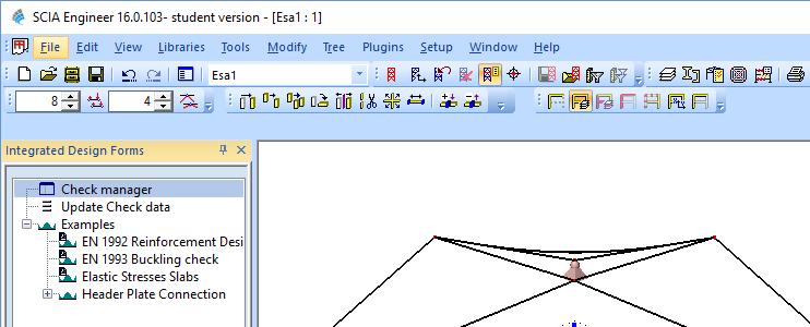
1 Design of a reinforced concrete 4-hypar shell with edge beams P.C.J. Hoogenboom, 22 May 2016 SCIA stands for scientific analyser. The C in SCIA Engineering is not pronounced. Note that the first c in science is not pronounced either. This handout shows linear elastic analysis, linear buckling analysis and design of reinforcement. Start SCIA Engineer and start a new project. Double click on Analysis. Select General XYZ. Select Concrete C30/37. 1

 Modelling, 2) Analysis, 3) Studying the results.")
2 Also select Dynamics and Stability. The others we do not need today. By selecting the functionality we add things to the menu things that we later need. The left column is a tree that makes many of the commands available. Look around in the tree. It is roughly organised in 3 parts: 1) Modelling, 2) Analysis, 3) Studying the results. (Most structural analysis programs and finite element programs are organised in this way.) In addition the program can design dimensions, perform code checking and help you write a report. 2
 (0, 0,11) ( 25,25,0) (0, 25,10) z ( 25, 25, 0) (0, 25,10) (25, 0,10) y x (25,25,0)")
")
3 We will model a 4-hypar shell with a span of 50 m. ( 25, 0,10) (0, 0,11) ( 25,25,0) (0, 25,10) z ( 25, 25, 0) (0, 25,10) (25, 0,10) y x (25,25,0) (25, 25, 0) Double click on Structure -> 2D member -> Shell. Enter the thickness of 90 mm. Note that in this box we can also change the z axis of the local coordinate system (LCS) (inwards or outwards). Perhaps we need to do this later. 3


4 We enter one of the four hypars by typing the corner coordinates x, y, z on the command line. A command can be ended by clicking right and on end. If you want to get out of a command then press esc three times. The other three hypars can be entered in the same way. 4


5 For entering edge beams we first need to define a cross-section. 5


6 To add an edge beam to the model, click on a node and then on another node. 6


7 Repeat this for all edges including the interior edges. The shell is simply supported in 4 nodes. 7


8 Click in the drawing on a support point four times. We can check the supports by toggling them on and enlarging them. There is only self-weight on the shell. So one load case and one load combination. 8


9 Let s perform a linear elastic analysis. Note that the mesh is generated automatically. 9


10 Note that the software has done an equilibrium check for us. Since the load and the support reactions are in equilibrium the equations have been solved accurately. Let s look at the computation results. 10


11 All parts are connected properly. The element size in the hypar middles is good. At the edges the elements are probably too large. We can improve this later. The deformation at the supports is correct. The top of the shell moves up, which is unexpected but possible. The displacement of 214 mm is large. But there is no practical reason why it is too large. Of course, when we add creep, wind load and snow load the deformation will be very large. Probably too large. But it is not easy to define too large for shell structures. 11
 Note the edge disturbances. 30 N/mm 2 tension / 500 x 100 = 6 % reinforcement. This might not fit.")
12 Normal forces in the edge beams and interior beams. There is tension in the top, due to the camber. Perhaps there is no need for the interior beams. First principal stress in the top of the shell. (The minus sign refers to the negative side of the local z axis.) Note the edge disturbances. 30 N/mm 2 tension / 500 x 100 = 6 % reinforcement. This might not fit. Since it is due to an edge disturbance we can also let it crack. 12


13 Smallest principal stress in the top of the shell. Minus refers to the surface on the negative side of the local z axis. If the stress is not symmetrical you need to change the z axis of the local coordinate system. 59 N/mm 2 is too large. It is very local. Probably a singularity due to the point support. In reality this point support is distributed over some area. We better check the stresses at the support with a simple hand calculation instead of by finite element analysis. Let s have a look at the directions of the principal normal forces. The shell edges help the edge beams. Around the top there is a compression-tension system that seems to load itself. This calls for design improvements. (Not now.) 13


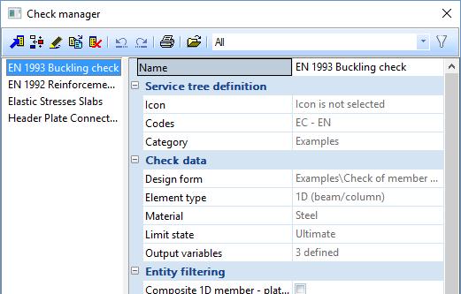
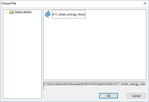
14 Directions of the principal moments. The moments in the edge disturbances are in the expected direction. Marieke Vergeer has made a small program that displays the strain energy in shells. Let s see of this works. The name of the program is b17_strain_energy_check.clc. It can be downloaded from (23 KB) The *.clc program needs to be copied to the folder C:\Users\Documents\ESA16\OpenChecks\ We need to load the program in SCIA. 14

15 15


 You can use not only computation results but also model data such as node coordinates.")
16 The quantity α is the ratio of the membrane strain energy and the bending strain energy. Where α = 1 the load is carried in by membrane forces. Where α = -1 the load is carried by moments. It gives in one contour plot an overview of the shell behaviour. There is a lot of moment in the hypars. Mostly at the interior beams. We cannot do much about these because they are due to edge disturbances. You can write your own programs in SCIA with a tool called design forms builder. (Not know) You can use not only computation results but also model data such as node coordinates. This program (*.CLS) is first compiled (*.CLC) and then loaded into SCIA. 16


17 Let s design reinforcement. We first need to align the element coordinate systems in the reinforcement directions. The element coordinate systems are in the diagonal directions of the hypars. However, we want the reinforcement in parallel to the edge beams. Therefore, we need to rotate the coordinate systems. (We would need much less reinforcement if the bars are in the principal directions of the membrane forces. However, this would be difficult to build.) ` 17

 When we zoom in we see that now the element coordinate systems are in the correct direction.")

18 Select a hypar by clicking on the edge. Rotate the LCS angle over 45 o (local coordinate system). We do this for all four hypars. (You might want to rotate some -45 o.) We need to do a new computation because the program forgets the calculation results when we rotate coordinate systems. (This can be programmed smarter.) When we zoom in we see that now the element coordinate systems are in the correct direction. Now we can display the reinforcement requirements. nxd and nyd are the membrane forces per length that the reinforcement needs to carry in the x direction and the y direction, respectively (nxd = nxx + nxy ). The moments are neglected. Only tension is important. ncd is the membrane force per length that the concrete needs to carry. 18


19 mxd and myd are the moments per length that the reinforcement needs to carry in the x and the y direction, respectively. The membrane forces are neglected. For most of the shell a mesh of 12 mm bars spaced 200 mm is sufficient. 500 N/mm 2 /1.15 x π/4 x (12 mm) 2 x 1000 mm / (200 mm) = N/m = 245 kn/m. 19


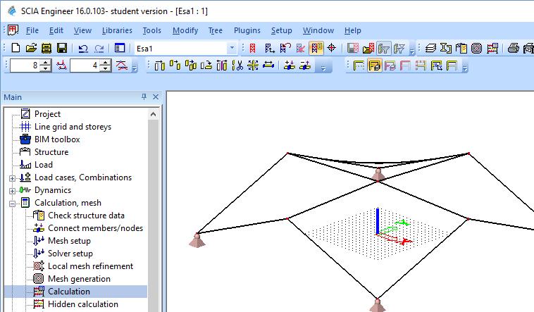
20 Let s check stability. 20
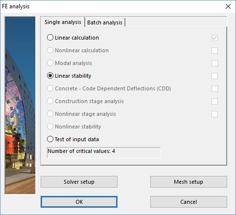

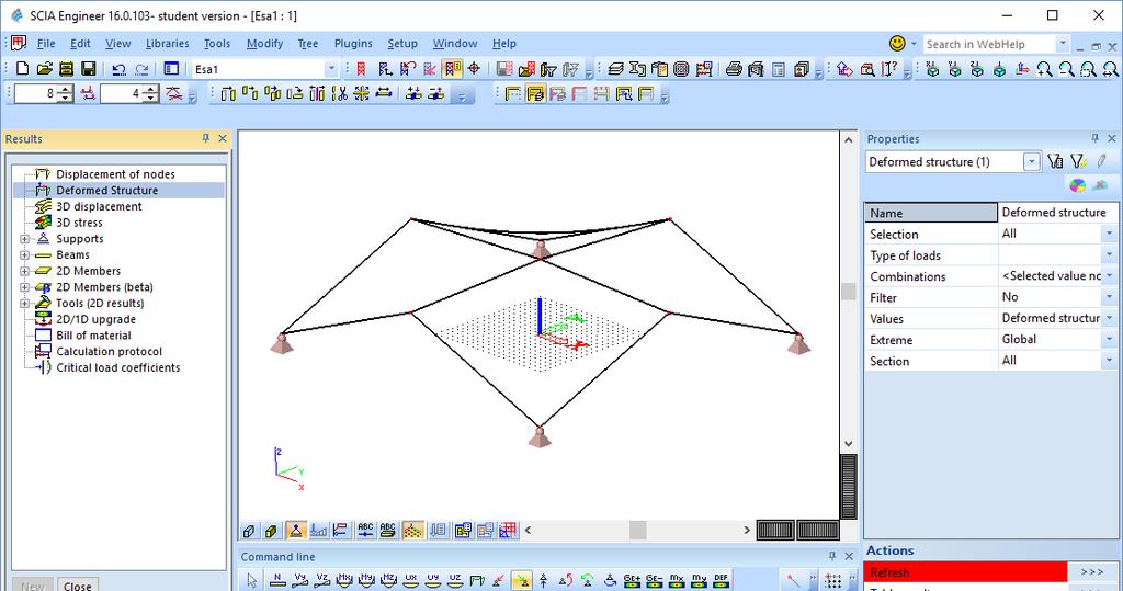
21 21
 This critical load clearly is not sufficient. The deformation shows that we need stiffer edge beams.")
22 The first buckling mode has a buckling load factor of This means that the shell buckles at a load of 90% of its self-weight. Note that the buckling mode can be shown up or down. (Like a column can buckle to the left or to the right.) This critical load clearly is not sufficient. The deformation shows that we need stiffer edge beams. Have a look at the other buckling modes too. The number of buckling modes that are computed can be set in can be selected in Solver Setup. You can also change the finite element size in Mesh Setup. Half the element size, perform the analysis again and if the important results do not change much than the element size is sufficiently small. 22
Revised Sheet Metal Simulation, J.E. Akin, Rice University
 Revised Sheet Metal Simulation, J.E. Akin, Rice University A SolidWorks simulation tutorial is just intended to illustrate where to find various icons that you would need in a real engineering analysis.
Deep Beam With Web Opening
 Deep Beam With Web Opening Name: Path: Keywords: DeepBeamWithWebOpening/deepbeam /Examples//DeepBeamWithWebOpening/deepbeam analys: linear static. constr: suppor. elemen: cq16m ct12m pstres. load: force
Scientific Manual FEM-Design 17.0
 Scientific Manual FEM-Design 17. 1.4.6 Calculations considering diaphragms All of the available calculation in FEM-Design can be performed with diaphragms or without diaphragms if the diaphragms were defined
Figure 30. Degrees of freedom of flat shell elements
 Shell finite elements There are three types of shell finite element; 1) flat elements, 2) elements based on the Sanders-Koiter equations and 3) elements based on reduction of a solid element. Flat elements
Elastic Analysis of a Deep Beam with Web Opening
 Elastic Analysis of a Deep Beam with Web Opening Outline 1 Description 2 Finite Element Model 2.1 Units 2.2 Geometry definition 2.3 Properties 2.4 Boundary conditions 2.4.1 Constraints 2.4.2 Vertical load
Engineering Effects of Boundary Conditions (Fixtures and Temperatures) J.E. Akin, Rice University, Mechanical Engineering
 J.E. Akin, Rice University, Mechanical Engineering") Engineering Effects of Boundary Conditions (Fixtures and Temperatures) J.E. Akin, Rice University, Mechanical Engineering Here SolidWorks stress simulation tutorials will be re-visited to show how they
Engineering Effects of Boundary Conditions (Fixtures and Temperatures) J.E. Akin, Rice University, Mechanical Engineering Here SolidWorks stress simulation tutorials will be re-visited to show how they
DESIGN AND ANALYSIS OF MEMBRANE STRUCTURES IN FEM-BASED SOFTWARE MASTER THESIS
 DESIGN AND ANALYSIS OF MEMBRANE STRUCTURES IN FEM-BASED SOFTWARE MASTER THESIS ARCHINEER INSTITUTES FOR MEMBRANE AND SHELL TECHNOLOGIES, BUILDING AND REAL ESTATE e.v. ANHALT UNIVERSITY OF APPLIED SCIENCES
General Information Project management Introduction... 4 Getting Started Input geometry... 7
 Tutorial Shell Tutorial Shell All information in this document is subject to modification without prior notice. No part or this manual may be reproduced, stored in a database or retrieval system or published,
Guidelines for proper use of Plate elements
 Guidelines for proper use of Plate elements In structural analysis using finite element method, the analysis model is created by dividing the entire structure into finite elements. This procedure is known
Exercise 1. 3-Point Bending Using the Static Structural Module of. Ansys Workbench 14.0
 Exercise 1 3-Point Bending Using the Static Structural Module of Contents Ansys Workbench 14.0 Learn how to...1 Given...2 Questions...2 Taking advantage of symmetries...2 A. Getting started...3 A.1 Choose
Manual for Computational Exercises
 Manual for the computational exercise in TMM4160 Fracture Mechanics Page 1 of 32 TMM4160 Fracture Mechanics Manual for Computational Exercises Version 3.0 Zhiliang Zhang Dept. of Structural Engineering
Reinforced concrete beam under static load: simulation of an experimental test
 Reinforced concrete beam under static load: simulation of an experimental test analys: nonlin physic. constr: suppor. elemen: bar cl12i cl3cm compos cq16m interf pstres reinfo struct. load: deform weight.
Revision of the SolidWorks Variable Pressure Simulation Tutorial J.E. Akin, Rice University, Mechanical Engineering. Introduction
 Revision of the SolidWorks Variable Pressure Simulation Tutorial J.E. Akin, Rice University, Mechanical Engineering Introduction A SolidWorks simulation tutorial is just intended to illustrate where to
WP1 NUMERICAL BENCHMARK INVESTIGATION
 WP1 NUMERICAL BENCHMARK INVESTIGATION 1 Table of contents 1 Introduction... 3 2 1 st example: beam under pure bending... 3 2.1 Definition of load application and boundary conditions... 4 2.2 Definition
Topic Training Load generators
 Topic Training Load generators Topic Training Load generators All information in this document is subject to modification without prior notice. No part of this manual may be reproduced, stored in a database
TABLE OF CONTENTS WHAT IS ADVANCE DESIGN? INSTALLING ADVANCE DESIGN... 8 System requirements... 8 Advance Design installation...
 Starting Guide 2019 TABLE OF CONTENTS INTRODUCTION... 5 Welcome to Advance Design... 5 About this guide... 6 Where to find information?... 6 Contacting technical support... 6 WHAT IS ADVANCE DESIGN?...
Advanced Concept Training
 Advanced Concept Training Reinforced concrete (EN 1992) 2D members Reinforced concrete (EN 1992) 2D members All information in this document is subject to modification without prior notice. No part of
Advanced Professional Training
 Advanced Professional Training Non Linea rand Stability All information in this document is subject to modification without prior notice. No part of this manual may be reproduced, stored in a database
Settlement of a circular silo foundation
 Engineering manual No. 22 Updated: 02/2018 Settlement of a circular silo foundation Program: FEM File: Demo_manual_22.gmk The objective of this manual is to describe the solution to a circular silo foundation
EXACT BUCKLING SOLUTION OF COMPOSITE WEB/FLANGE ASSEMBLY
 EXACT BUCKLING SOLUTION OF COMPOSITE WEB/FLANGE ASSEMBLY J. Sauvé 1*, M. Dubé 1, F. Dervault 2, G. Corriveau 2 1 Ecole de technologie superieure, Montreal, Canada 2 Airframe stress, Advanced Structures,
Chapter 3 Analysis of Original Steel Post
 Chapter 3. Analysis of original steel post 35 Chapter 3 Analysis of Original Steel Post This type of post is a real functioning structure. It is in service throughout the rail network of Spain as part
Exercise 1. 3-Point Bending Using the GUI and the Bottom-up-Method
 Exercise 1 3-Point Bending Using the GUI and the Bottom-up-Method Contents Learn how to... 1 Given... 2 Questions... 2 Taking advantage of symmetries... 2 A. Preprocessor (Setting up the Model)... 3 A.1
SUBMERGED CONSTRUCTION OF AN EXCAVATION
 2 SUBMERGED CONSTRUCTION OF AN EXCAVATION This tutorial illustrates the use of PLAXIS for the analysis of submerged construction of an excavation. Most of the program features that were used in Tutorial
COMPUTER AIDED ENGINEERING. Part-1
 COMPUTER AIDED ENGINEERING Course no. 7962 Finite Element Modelling and Simulation Finite Element Modelling and Simulation Part-1 Modeling & Simulation System A system exists and operates in time and space.
Introduction to the Finite Element Method (3)
") Introduction to the Finite Element Method (3) Petr Kabele Czech Technical University in Prague Faculty of Civil Engineering Czech Republic petr.kabele@fsv.cvut.cz people.fsv.cvut.cz/~pkabele 1 Outline
Introduction to the Finite Element Method (3) Petr Kabele Czech Technical University in Prague Faculty of Civil Engineering Czech Republic petr.kabele@fsv.cvut.cz people.fsv.cvut.cz/~pkabele 1 Outline
3. Check by Eurocode 3 a Steel Truss
 TF 3. Check by Eurocode 3 a Steel Truss Applicable CivilFEM Product: All CivilFEM Products Level of Difficulty: Moderate Interactive Time Required: 40 minutes Discipline: Structural Steel Analysis Type:
Investigation of the behaviour of single span reinforced concrete historic bridges by using the finite element method
 Structural Studies, Repairs and Maintenance of Heritage Architecture XI 279 Investigation of the behaviour of single span reinforced concrete historic bridges by using the finite element method S. B. Yuksel
E and. L q. AE q L AE L. q L
 STRUTURL NLYSIS [SK 43] EXERISES Q. (a) Using basic concepts, members towrds local axes is, E and q L, prove that the equilibrium equation for truss f f E L E L E L q E q L With f and q are both force
Advance Design. Tutorial
 TUTORIAL 2018 Advance Design Tutorial Table of Contents About this tutorial... 1 How to use this guide... 3 Lesson 1: Preparing and organizing your model... 4 Step 1: Start Advance Design... 5 Step 2:
Embedded Reinforcements
 Embedded Reinforcements Gerd-Jan Schreppers, January 2015 Abstract: This paper explains the concept and application of embedded reinforcements in DIANA. Basic assumptions and definitions, the pre-processing
How to re-open the black box in the structural design of complex geometries
 Structures and Architecture Cruz (Ed) 2016 Taylor & Francis Group, London, ISBN 978-1-138-02651-3 How to re-open the black box in the structural design of complex geometries K. Verbeeck Partner Ney & Partners,
Torsional-lateral buckling large displacement analysis with a simple beam using Abaqus 6.10
 Torsional-lateral buckling large displacement analysis with a simple beam using Abaqus 6.10 This document contains an Abaqus tutorial for performing a buckling analysis using the finite element program
Finite Element Analysis of a 10 x 22 FRP Building for TRACOM Corporation
 Finite Element Analysis of a 10 x 22 FRP Building for TRACOM Corporation May 29, 2007 A. Background TRACOM Corporation designs and constructs Fiber Reinforced Plastic Buildings for use as shelters around
Tekla Structures Analysis Guide. Product version 21.0 March Tekla Corporation
 Tekla Structures Analysis Guide Product version 21.0 March 2015 2015 Tekla Corporation Contents 1 Getting started with analysis... 7 1.1 What is an analysis model... 7 Analysis model objects...9 1.2 About
CE Advanced Structural Analysis. Lab 4 SAP2000 Plane Elasticity
 Department of Civil & Geological Engineering COLLEGE OF ENGINEERING CE 463.3 Advanced Structural Analysis Lab 4 SAP2000 Plane Elasticity February 27 th, 2013 T.A: Ouafi Saha Professor: M. Boulfiza 1. Rectangular
Start AxisVM by double-clicking the AxisVM icon in the AxisVM folder, found on the Desktop, or in the Start, Programs Menu.
 1. BEAM MODEL Start New Start AxisVM by double-clicking the AxisVM icon in the AxisVM folder, found on the Desktop, or in the Start, Programs Menu. Create a new model with the New Icon. In the dialogue
PLAXIS 2D - SUBMERGED CONSTRUCTION OF AN EXCAVATION
 PLAXIS 2D - SUBMERGED CONSTRUCTION OF AN EXCAVATION 3 SUBMERGED CONSTRUCTION OF AN EXCAVATION This tutorial illustrates the use of PLAXIS for the analysis of submerged construction of an excavation. Most
PTC Newsletter January 14th, 2002
 PTC Email Newsletter January 14th, 2002 PTC Product Focus: Pro/MECHANICA (Structure) Tip of the Week: Creating and using Rigid Connections Upcoming Events and Training Class Schedules PTC Product Focus:
BE PLATES. Manual. July Friedel Hartmann. statik.de statik.de
 INSTALLATION Manual July 2017 Friedel Hartmann www.be statik.de www.winfem.de hartmann@be statik.de 1.1 INSTALLATION 1. INSTALLATION... 4 1.1. STARTING THE PROGRAM... 4 1.2. THE MAIN MENU... 4 1.3. POSITIONS...
Installation Guide. Beginners guide to structural analysis
 Installation Guide To install Abaqus, students at the School of Civil Engineering, Sohngaardsholmsvej 57, should log on to \\studserver, whereas the staff at the Department of Civil Engineering should
SAFI Sample Projects. Design of a Steel Structure. SAFI Quality Software Inc. 3393, chemin Sainte-Foy Ste-Foy, Quebec, G1X 1S7 Canada
 SAFI Sample Projects Design of a Steel Structure SAFI Quality Software Inc. 3393, chemin Sainte-Foy Ste-Foy, Quebec, G1X 1S7 Canada Contact: Rachik Elmaraghy, P.Eng., M.A.Sc. Tel.: 1-418-654-9454 1-800-810-9454
Case Study - Vierendeel Frame Part of Chapter 12 from: MacLeod I A (2005) Modern Structural Analysis, ICE Publishing
 Modern Structural Analysis, ICE Publishing") Case Study - Vierendeel Frame Part of Chapter 1 from: MacLeod I A (005) Modern Structural Analysis, ICE Publishing Iain A MacLeod Contents Contents... 1 1.1 Vierendeel frame... 1 1.1.1 General... 1 1.1.
Case Study - Vierendeel Frame Part of Chapter 1 from: MacLeod I A (005) Modern Structural Analysis, ICE Publishing Iain A MacLeod Contents Contents... 1 1.1 Vierendeel frame... 1 1.1.1 General... 1 1.1.
Introduction. Section 3: Structural Analysis Concepts - Review
 Introduction In this class we will focus on the structural analysis of framed structures. Framed structures consist of components with lengths that are significantly larger than crosssectional areas. We
Finite Element Specialists and Engineering Consultants
 Finite Element Specialists and Engineering Consultants Limit Analysis Using Finite Element Techniques Seminar for the Advanced Structural Engineering Module College of Engineering, Mathematics & Physical
Behaviour of cold bent glass plates during the shaping process
 Behaviour of cold bent glass plates during the shaping process Kyriaki G. DATSIOU *, Mauro OVEREND a * Department of Engineering, University of Cambridge Trumpington Street, Cambridge, CB2 1PZ, UK kd365@cam.ac.uk
ENGINEERING TRIPOS PART IIA FINITE ELEMENT METHOD
 ENGINEERING TRIPOS PART IIA LOCATION: DPO EXPERIMENT 3D7 FINITE ELEMENT METHOD Those who have performed the 3C7 experiment should bring the write-up along to this laboratory Objectives Show that the accuracy
Tutorial 1: Welded Frame - Problem Description
 Tutorial 1: Welded Frame - Problem Description Introduction In this first tutorial, we will analyse a simple frame: firstly as a welded frame, and secondly as a pin jointed truss. In each case, we will
Formation SCIA ESA PT
 Formation SCIA ESA PT General Environment: Options, Setup, Help New Project: Project data Windows/toolbars : - Workspace, Window with Main tree and window for properties - Windows change place / close
Extraction of Strut and Tie Model From 3D Solid Element Mesh Analysis
 International Conference on Sustainable Built Environment Extraction of Strut and Tie Model From 3D Solid Element Mesh Analysis Dammika Abeykoon, Naveed Anwar, Jason C. Rigon ICSBE 2010 12-14 December
Similar Pulley Wheel Description J.E. Akin, Rice University
 Similar Pulley Wheel Description J.E. Akin, Rice University The SolidWorks simulation tutorial on the analysis of an assembly suggested noting another type of boundary condition that is not illustrated
Buckling Analysis of a Thin Plate
 Buckling Analysis of a Thin Plate Outline 1 Description 2 Modeling approach 3 Finite Element Model 3.1 Units 3.2 Geometry definition 3.3 Properties 3.4 Boundary conditions 3.5 Loads 3.6 Meshing 4 Structural
SETTLEMENT OF A CIRCULAR FOOTING ON SAND
 1 SETTLEMENT OF A CIRCULAR FOOTING ON SAND In this chapter a first application is considered, namely the settlement of a circular foundation footing on sand. This is the first step in becoming familiar
Learning Module 8 Shape Optimization
 Learning Module 8 Shape Optimization What is a Learning Module? Title Page Guide A Learning Module (LM) is a structured, concise, and self-sufficient learning resource. An LM provides the learner with
CITY AND GUILDS 9210 UNIT 135 MECHANICS OF SOLIDS Level 6 TUTORIAL 15 - FINITE ELEMENT ANALYSIS - PART 1
 Outcome 1 The learner can: CITY AND GUILDS 9210 UNIT 135 MECHANICS OF SOLIDS Level 6 TUTORIAL 15 - FINITE ELEMENT ANALYSIS - PART 1 Calculate stresses, strain and deflections in a range of components under
Finite Element Course ANSYS Mechanical Tutorial Tutorial 4 Plate With a Hole
 Problem Specification Finite Element Course ANSYS Mechanical Tutorial Tutorial 4 Plate With a Hole Consider the classic example of a circular hole in a rectangular plate of constant thickness. The plate
ixcube 4-10 Brief introduction for membrane and cable systems.
 ixcube 4-10 Brief introduction for membrane and cable systems. ixcube is the evolution of 20 years of R&D in the field of membrane structures so it takes a while to understand the basic features. You must
Aufgabe 1: Dreipunktbiegung mit ANSYS Workbench
 Aufgabe 1: Dreipunktbiegung mit ANSYS Workbench Contents Beam under 3-Pt Bending [Balken unter 3-Pkt-Biegung]... 2 Taking advantage of symmetries... 3 Starting and Configuring ANSYS Workbench... 4 A. Pre-Processing:
Engineering Analysis
 Engineering Analysis with SOLIDWORKS Simulation 2018 Paul M. Kurowski SDC PUBLICATIONS Better Textbooks. Lower Prices. www.sdcpublications.com Powered by TCPDF (www.tcpdf.org) Visit the following websites
Linear Static Analysis of a Cantilever Beam
 Linear Static Analysis of a Cantilever Beam Outline 1 Theory 2 Finite Element Model 2.1 Units 2.2 Geometry Definition 2.3 Properties 2.4 Boundary Conditions 2.5 Loads 2.6 Meshing 3 Linear Static Analysis
Technical Issues. Frequently Asked Questions Frequently Encountered Errors. - Featuring - ADAPT-ABI 2009
 Technical Issues Frequently Asked Questions Frequently Encountered Errors - Featuring - ADAPT-ABI 2009 ADAPT Corporation, USA ADAPT International Pvt. Ltd, Kolkata, India Tuesday, November 17, 2009 1 What
Elastic Analysis of a Bending Plate
 analys: linear static. constr: suppor. elemen: plate q12pl. load: elemen face force. materi: elasti isotro. option: direct units. post: binary ndiana. pre: dianai. result: cauchy displa extern force green
CE2302 STRUCTURAL ANALYSIS I Important Questions PART B
 CE2302 STRUCTURAL ANALYSIS I Important Questions PART B UNIT I 1. Determine the vertical and horizontal displacement of the joint B in a pin jointed frame shown in fig. 2. The cross sectional area of each
General Applications
 Chapter General Applications The general analysis modules can be used to calculate section properties, wind pressures on buildings and evaluate drainage systems of building roofs. General Applications
Problem description. Prescribed. force. Unit thickness, plane stress. Transverse direction. Prescribed. displacement. Longitudinal direction
 Problem description Two desirable features in a material model are: 1) the ability to reproduce experimental data in an analysis that corresponds to the experiment and 2) that the material model be stable
Lab#5 Combined analysis types in ANSYS By C. Daley
 Engineering 5003 - Ship Structures I Lab#5 Combined analysis types in ANSYS By C. Daley Overview In this lab we will model a simple pinned column using shell elements. Once again, we will use SpaceClaim
Slope Deflection Method
 Slope Deflection Method Lesson Objectives: 1) Identify the formulation and sign conventions associated with the Slope Deflection method. 2) Derive the Slope Deflection Method equations using mechanics
Supplementary information
 Modern Structural Analysis - Introduction to Modelling Supplementary information Chapter 3 Section 5.10 Equivalent beam for parallel chord trusses The cross references in the form n.m or n.m.p are to sub-sections
CONTACT STATE AND STRESS ANALYSIS IN A KEY JOINT BY FEM
 PERJODICA POLYTECHNICA SER. ME CH. ENG. VOL. 36, NO. 1, PP. -15-60 (1992) CONTACT STATE AND STRESS ANALYSIS IN A KEY JOINT BY FEM K. VARADI and D. M. VERGHESE Institute of Machine Design Technical University,
MAE Advanced Computer Aided Design. 01. Introduction Doc 02. Introduction to the FINITE ELEMENT METHOD
 MAE 656 - Advanced Computer Aided Design 01. Introduction Doc 02 Introduction to the FINITE ELEMENT METHOD The FEM is A TOOL A simulation tool The FEM is A TOOL NOT ONLY STRUCTURAL! Narrowing the problem
Module 1.7W: Point Loading of a 3D Cantilever Beam
 Module 1.7W: Point Loading of a 3D Cantilever Beam Table of Contents Page Number Problem Description 2 Theory 2 Workbench Analysis System 4 Engineering Data 5 Geometry 6 Model 11 Setup 13 Solution 14 Results
WORKSHOP 6.3 WELD FATIGUE USING NOMINAL STRESS METHOD. For ANSYS release 14
 WORKSHOP 6.3 WELD FATIGUE USING NOMINAL STRESS METHOD For ANSYS release 14 Objective: In this workshop, a weld fatigue analysis on a VKR-beam with a plate on top using the nominal stress method is demonstrated.
Linear Buckling Analysis of a Plate
 Workshop 9 Linear Buckling Analysis of a Plate Objectives Create a geometric representation of a plate. Apply a compression load to two apposite sides of the plate. Run a linear buckling analysis. 9-1
Start AxisVM by double-clicking the AxisVM icon in the AxisVM folder, found on the Desktop, or in the Start, Programs Menu.
 4. MEMBRANE MODEL 1.1. Preprocessing with surface elements Start New Start AxisVM by double-clicking the AxisVM icon in the AxisVM folder, found on the Desktop, or in the Start, Programs Menu. Create a
DIFFERENT TECHNIQUES FOR THE MODELING OF POST-TENSIONED CONCRETE BOX-GIRDER BRIDGES
 DIFFERENT TECHNIQUES FOR THE MODELING OF POST-TENSIONED CONCRETE BOX-GIRDER BRIDGES Deepak Rayamajhi Naveed Anwar Jimmy Chandra Graduate Student Associate Director Graduate Student Structural Engineering
Solved with COMSOL Multiphysics 4.2
 Pratt Truss Bridge Introduction This example is inspired by a classic bridge type called a Pratt truss bridge. You can identify a Pratt truss by its diagonal members, which (except for the very end ones)
FEA TUTORIAL 2D STRESS ANALYSIS OF A THIN BAR (Using ProMechanica Wildfire 1.0)
") FEA TUTORIAL 2D STRESS ANALYSIS OF A THIN BAR (Using ProMechanica Wildfire 1.0) Introduction: A simple 2D stress analysis of a thin bar with a hole will be performed using Pro/Mechanica. The bar will be
FEA TUTORIAL 2D STRESS ANALYSIS OF A THIN BAR (Using ProMechanica Wildfire 1.0) Introduction: A simple 2D stress analysis of a thin bar with a hole will be performed using Pro/Mechanica. The bar will be
Introduction To Finite Element Analysis
 Creating a Part In this part of the tutorial we will introduce you to some basic modelling concepts. If you are already familiar with modelling in Pro Engineer you will find this section very easy. Before
Tutorial. Steel frame
 Tutorial Steel frame Tutorial Concrete frame All information in this document is subject to modification without prior notice. No part of this manual may be reproduced, stored in a database or retrieval
A rubber O-ring is pressed between two frictionless plates as shown: 12 mm mm
 Problem description A rubber O-ring is pressed between two frictionless plates as shown: Prescribed displacement C L 12 mm 48.65 mm A two-dimensional axisymmetric analysis is appropriate here. Data points
Concrete Plate Concrete Slab (ACI )
") Tutorial Tutorial Concrete Plate Concrete Slab (ACI 318-08) Tutorial Concrete Plate All information in this document is subject to modification without prior notice. No part or this manual may be reproduced,
Tutorial Tutorial Concrete Plate Concrete Slab (ACI 318-08) Tutorial Concrete Plate All information in this document is subject to modification without prior notice. No part or this manual may be reproduced,
FOUNDATION IN OVERCONSOLIDATED CLAY
 1 FOUNDATION IN OVERCONSOLIDATED CLAY In this chapter a first application of PLAXIS 3D is considered, namely the settlement of a foundation in clay. This is the first step in becoming familiar with the
BEARING CAPACITY OF CIRCULAR FOOTING
 This document describes an example that has been used to verify the ultimate limit state capabilities of PLAXIS. The problem involves the bearing capacity of a smooth circular footing on frictional soil.
ME 475 FEA of a Composite Panel
 ME 475 FEA of a Composite Panel Objectives: To determine the deflection and stress state of a composite panel subjected to asymmetric loading. Introduction: Composite laminates are composed of thin layers
Generative Part Structural Analysis Fundamentals
 CATIA V5 Training Foils Generative Part Structural Analysis Fundamentals Version 5 Release 19 September 2008 EDU_CAT_EN_GPF_FI_V5R19 About this course Objectives of the course Upon completion of this course
Example: 3D structural model of a building frame with pinned connections
 SAFIR training session level 1 Johns Hopkins University, Baltimore Example: 3D structural model of a building frame with pinned connections 3D building frame with concrete columns and steel beams T. Gernay
Exercise 1: 3-Pt Bending using ANSYS Workbench
 Exercise 1: 3-Pt Bending using ANSYS Workbench Contents Starting and Configuring ANSYS Workbench... 2 1. Starting Windows on the MAC... 2 2. Login into Windows... 2 3. Start ANSYS Workbench... 2 4. Configuring
Introduction to MSC.Patran
 Exercise 1 Introduction to MSC.Patran Objectives: Create geometry for a Beam. Add Loads and Boundary Conditions. Review analysis results. MSC.Patran 301 Exercise Workbook - Release 9.0 1-1 1-2 MSC.Patran
FE ANALYSES OF STABILITY OF SINGLE AND DOUBLE CORRUGATED BOARDS
 Proceedings of ICAD26 FE ANALYSES OF STABILITY OF SINGLE AND DOUBLE CORRUGATED BOARDS ICAD-26-43 Enrico Armentani enrico.armentani@unina.it University of Naples P.le V. Tecchio, 8 8125 Naples Italy Francesco
UNIT III KANI S METHOD
 SIDDHARTH GROUP OF INSTITUTIONS :: PUTTUR Siddharth Nagar, Narayanavanam Road 517583 QUESTION BANK (DESCRIPTIVE) Subject with Code : SA-II (13A01505) Year & Sem: III-B.Tech & I-Sem Course & Branch: B.Tech
Static Stress Analysis
 Static Stress Analysis Determine stresses and displacements in a connecting rod assembly. Lesson: Static Stress Analysis of a Connecting Rod Assembly In this tutorial we determine the effects of a 2,000-pound
Application of Shell elements to buckling-analyses of thin-walled composite laminates
 Application of Shell elements to buckling-analyses of thin-walled composite laminates B.A. Gӧttgens MT 12.02 Internship report Coach: Dr. R. E. Erkmen University of Technology Sydney Department of Civil
Applying FEA to a tensile structure (Imperial)
") Applying FEA to a tensile structure (Imperial) The starting point for any FEA analysis is a good understanding of what results we expect. This can be from prior experience with similar structures, or by
Applying FEA to a tensile structure (Imperial) The starting point for any FEA analysis is a good understanding of what results we expect. This can be from prior experience with similar structures, or by
Analysis of Composite Aerospace Structures Finite Elements Professor Kelly
 Analysis of Composite Aerospace Structures Finite Elements Professor Kelly John Middendorf #3049731 Assignment #3 I hereby certify that this is my own and original work. Signed, John Middendorf Analysis
Module 3: Buckling of 1D Simply Supported Beam
 Module : Buckling of 1D Simply Supported Beam Table of Contents Page Number Problem Description Theory Geometry 4 Preprocessor 7 Element Type 7 Real Constants and Material Properties 8 Meshing 9 Solution
CHAPTER 4. Numerical Models. descriptions of the boundary conditions, element types, validation, and the force
 CHAPTER 4 Numerical Models This chapter presents the development of numerical models for sandwich beams/plates subjected to four-point bending and the hydromat test system. Detailed descriptions of the
1. INTRODUCTION. A shell may be defined as the solid material enclosed. between two closely spaced curved surfaces (1), the distance
, the distance") 1 1. INTRODUCTION 1.1. GENERAL A shell may be defined as the solid material enclosed between two closely spaced curved surfaces (1), the distance between these two surfaces being the thickness of the shell.
1 1. INTRODUCTION 1.1. GENERAL A shell may be defined as the solid material enclosed between two closely spaced curved surfaces (1), the distance between these two surfaces being the thickness of the shell.
ANSYS AIM Tutorial Structural Analysis of a Plate with Hole
 ANSYS AIM Tutorial Structural Analysis of a Plate with Hole Author(s): Sebastian Vecchi, ANSYS Created using ANSYS AIM 18.1 Problem Specification Pre-Analysis & Start Up Analytical vs. Numerical Approaches
Modeling Skills Stress Analysis J.E. Akin, Rice University, Mech 417
 Introduction Modeling Skills Stress Analysis J.E. Akin, Rice University, Mech 417 Most finite element analysis tasks involve utilizing commercial software, for which you do not have the source code. Thus,
ME 442. Marc/Mentat-2011 Tutorial-1
 ME 442 Overview Marc/Mentat-2011 Tutorial-1 The purpose of this tutorial is to introduce the new user to the MSC/MARC/MENTAT finite element program. It should take about one hour to complete. The MARC/MENTAT
THREE DIMENSIONAL ACES MODELS FOR BRIDGES
 THREE DIMENSIONAL ACES MODELS FOR BRIDGES Noel Wenham, Design Engineer, Wyche Consulting Joe Wyche, Director, Wyche Consulting SYNOPSIS Plane grillage models are widely used for the design of bridges,