Buckling Analysis of a Thin Plate
|
|
|
- Dinah Fisher
- 5 years ago
- Views:
Transcription


1 Buckling Analysis of a Thin Plate
2 Outline 1 Description 2 Modeling approach 3 Finite Element Model 3.1 Units 3.2 Geometry definition 3.3 Properties 3.4 Boundary conditions 3.5 Loads 3.6 Meshing 4 Structural linear static analysis 4.1 Analysis commands 4.2 Results Total displacement DtXYZ 5 Structural stability 5.1 Analysis commands 5.2 Results Total displacement DtXYZ Appendix A Additional information Buckling Analysis of a Thin Plate 2/19
3 1 Description In this example, the buckling behavior of a thin square plate is analyzed. As shown in Figure 1, the plate is subjected to a uniform compression load f. t f b b = 2000 mm t = 10 mm E = 2x10 5 N/mm 2 ν = 0.3 b f Figure 1: Thin plate under uniform compression loading Beyond a certain load value f crit (i.e., the critical load) the plate becomes unstable and buckles. According to Timoshenko and Gere 1, the critical buckling load for this example is f crit = 4π2 D b 2 withd = Et 3 12 (1 ν 2 ), where b is the length of the plate, t the thickness, E the Young s modulus and ν the Poisson s ratio. With reference to Figure 1, for the present example we have f crit = N/mm. 1 S. Timoshenko and J. M. Gere, Theory of elastic stability, 2nd ed., McGraw Hill, 1963 Buckling Analysis of a Thin Plate 3/19
4 2 Modeling approach As both membrane stresses and bending stresses are of importance, shell elements are used. No use is made of symmetry conditions and thus the entire domain is subdivided in finite elements. A rather coarse mesh of 4x4 elements is used and quadratic square elements will be employed. The plate is supported in Z-direction along its edges. In-plane displacements in the mid-points of the edges are supported as shown in Figure 2. Y Z X Figure 2: Model used in the finite element analysis (the supports in the X, Y and Z directions are colored in red, green and blue, respectively) Note that in spite of the fact that the geometry of the structure is two-dimensional, we should perform a three-dimensional structural analysis. That is because the model shows a phenomenon in the third dimension (i.e., the out-of-plane displacement). Buckling Analysis of a Thin Plate 4/19
![3 Finite Element Model For the modeling session we start a new project for structural analysis [Fig. 3].](/docs-images/84/91050132/images/5-2.jpg "The dimensions of the domain for the 3D model are set equal to 10 m. We will use quadratic quadrilateral finite elements. Main menu File New [Fig.")
5 3 Finite Element Model For the modeling session we start a new project for structural analysis [Fig. 3]. The dimensions of the domain for the 3D model are set equal to 10 m. We will use quadratic quadrilateral finite elements. Main menu File New [Fig. 3] Figure 3: New project dialog Buckling Analysis of a Thin Plate 5/19

![4] Property Panel [Fig.](/docs-images/84/91050132/images/6-3.jpg "5] Figure 4: Geometry browser Figure 5: Property Panel - Units")
6 3.1 Units We choose millimeter for the unit Length, ton for Mass and Newton for Force. Geometry browser Reference system Units [Fig. 4] Property Panel [Fig. 5] Figure 4: Geometry browser Figure 5: Property Panel - Units Buckling Analysis of a Thin Plate 6/19


7 3.2 Geometry definition We create the plate sheet. The coordinates to be used for this geometry are in Table 1. Main Menu Geometry Create Add polygon sheet [Fig. 6] Viewer Viewpoints Top View plate Table 1: plate coordinates Figure 6: Add plate sheet Figure 7: View of the plate geometry Buckling Analysis of a Thin Plate 7/19


![8] Property assignments Add new material [Fig. 9] [Fig.](/docs-images/84/91050132/images/8-5.jpg "10] Property assignments Add new geometry [Fig.")
8 3.3 Properties We assign the element class and the material and geometrical properties to the plate. We use curved shell elements with a thickness of 10 mm as shown in Figure 1. The material is assumed isotropic linear elastic and the material properties presented in Section 1 are used. Main Menu Geometry Analysis Property assignments [Fig. 8] Property assignments Add new material [Fig. 9] [Fig. 10] Property assignments Add new geometry [Fig. 11] Figure 9: Add new material steel Figure 8: Property assignments to plate Figure 10: Edit material plate Figure 11: Edit geometry thickness Buckling Analysis of a Thin Plate 8/19

9 3.4 Boundary conditions We now apply the boundary conditions shown in Figure 2. We first constrain the displacement in the X-direction at the top and bottom mid-nodes, then the displacement in the Y -direction at the left and right mid-nodes and, finally, the displacement of the edges in the Z-direction. Main Menu Geometry Analysis Attach support (x3) [Fig. 12] [Fig. 15] Figure 12: Apply constraints in the X-direction Figure 13: Apply constraints in the Y -direction Figure 14: Apply constraints in the Z-direction Buckling Analysis of a Thin Plate 9/19
10 Figure 15: Geometric model with constraints Buckling Analysis of a Thin Plate 10/19
 and bottom edges (100 N/mm). Main menu Geometry Analysis Attach load [Fig. 16] [Fig.")
![18] Figure 16: Apply a vertical load at top edge Figure 17: Apply a vertical load at bottom edge Figure](/docs-images/84/91050132/images/11-3.jpg "18: Top view of the model with the vertical loads Buckling Analysis of a Thin Plate https://dianafea.")
11 3.5 Loads We apply a vertical pressure to the plate by assigning a vertical distributed load at the top edge (-100 N/mm) and bottom edges (100 N/mm). Main menu Geometry Analysis Attach load [Fig. 16] [Fig. 18] Figure 16: Apply a vertical load at top edge Figure 17: Apply a vertical load at bottom edge Figure 18: Top view of the model with the vertical loads Buckling Analysis of a Thin Plate 11/19

12 Then, we need to create a load combination that considers the two vertical loads. This is needed during the setup of the buckling analysis as it will be considered as the buckling load. Main menu Loads Open geometry load combinations [Fig. 19] Figure 19: Load combination table Buckling Analysis of a Thin Plate 12/19

![20] Main Menu Geometry Analysis Generate mesh [Fig.](/docs-images/84/91050132/images/13-3.jpg "21] Figure 20: Mesh properties Figure 21: Finite element mesh Buckling Analysis of")
13 3.6 Meshing We set the mesh properties such that the elements size is 500 mm. Then, we generate the mesh. Main Menu Geometry Analysis Set mesh properties [Fig. 20] Main Menu Geometry Analysis Generate mesh [Fig. 21] Figure 20: Mesh properties Figure 21: Finite element mesh Buckling Analysis of a Thin Plate 13/19
 Analysis1 Rename Linear [Fig.")
14 4 Structural linear static analysis 4.1 Analysis commands We will first perform a linear elastic analysis for a quick assessment of the model. Main Menu Analysis New Analysis Analysis browser Right click ( ) Analysis1 Rename Linear [Fig. 22] Main Menu Analysis Run Analysis Figure 22: Analysis window Figure 23: Analysis tree Buckling Analysis of a Thin Plate 14/19

![Results browser Output linear static analysis Nodal results Displacements DtY [Fig. 24] [Fig.](/docs-images/84/91050132/images/15-3.jpg "25] Figure 24: Results browser - DtY Figure 25: Displacement DtY As shown in Figure 25, the numerical result obtained with is the")
15 4.2 Results Total displacement DtXYZ Here, we will compare the vertical displacement of the top of the plate obtained numerically with and analytically from the equation: u y = fb 2Et = 0.05 mm. Results browser Output linear static analysis Nodal results Displacements DtY [Fig. 24] [Fig. 25] Figure 24: Results browser - DtY Figure 25: Displacement DtY As shown in Figure 25, the numerical result obtained with is the same as that from the analytical solution. Buckling Analysis of a Thin Plate 15/19

![Analysis browser Right click ( ) Linear Add command Structural stability [Fig. 26] [Fig.](/docs-images/84/91050132/images/16-4.jpg "27] Analysis browser Structural stability Eigenvalue analysis Right click ( ) Define stability analysis Edit properties")
16 5 Structural stability 5.1 Analysis commands Now, we perform a structural stability analysis to derive the buckling load for the plate. Analysis browser Right click ( ) Linear Add command Structural stability [Fig. 26] [Fig. 27] Analysis browser Structural stability Eigenvalue analysis Right click ( ) Define stability analysis Edit properties [Fig. 28] Figure 26: Add command Figure 27: Analysis tree Figure 28: Buckling load Buckling Analysis of a Thin Plate 16/19

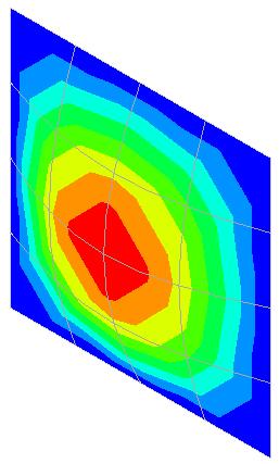
![30] Figure 29: Results browser - DtY Figure 30: Displacement DtXYZ As shown in Figure 30, the buckling load obtained from (1.7989 f = 179.](/docs-images/84/91050132/images/17-3.jpg "89 N/mm) is in good agreement with the theoretical value equal to 180.76 N/mm calculated in Section 1.")
17 5.2 Results Total displacement DtXYZ We will create a contour plot of the total displacement of the buckled plate. Results window Case Mode 1, Buckling value Results browser Output eigenvalue analysis Nodal results Displacements DtXYZ [Fig. 29] [Fig. 30] Figure 29: Results browser - DtY Figure 30: Displacement DtXYZ As shown in Figure 30, the buckling load obtained from ( f = N/mm) is in good agreement with the theoretical value equal to N/mm calculated in Section 1. Buckling Analysis of a Thin Plate 17/19
18 Appendix A Additional information Folder: Tutorials/BucklingPlate Number of elements 16 Keywords: analys: dynami nonlin physic transi. constr: suppor. elemen: beam class1 class3 curved enhanc l12be l12bea l6tru q20sh rectan shell sp2tr spring t15sh truss. load: base time weight. materi: elasti engmas isotro orthot spring unload. option: direct linese newton regula units. post: tabula. pre: dianai. result: accele displa total. Buckling Analysis of a Thin Plate 18/19
19 DIANA FEA BV Delftechpark 19a 2628 XJ Delft The Netherlands T +31 (0) F +31 (0) DIANA FEA BV Vlamoven TN Arnhem The Netherlands T +31 (0) F +31 (0)
Elastic Analysis of a Deep Beam with Web Opening
 Elastic Analysis of a Deep Beam with Web Opening Outline 1 Description 2 Finite Element Model 2.1 Units 2.2 Geometry definition 2.3 Properties 2.4 Boundary conditions 2.4.1 Constraints 2.4.2 Vertical load
Prescribed Deformations
 u Prescribed Deformations Outline 1 Description 2 Finite Element Model 2.1 Geometry Definition 2.2 Properties 2.3 Boundary Conditions 2.3.1 Constraints 2.3.2 Prescribed Deformation 2.4 Loads 2.4.1 Dead
Linear Static Analysis of a Cantilever Beam
 Linear Static Analysis of a Cantilever Beam Outline 1 Theory 2 Finite Element Model 2.1 Units 2.2 Geometry Definition 2.3 Properties 2.4 Boundary Conditions 2.5 Loads 2.6 Meshing 3 Linear Static Analysis
Outline. 3 Linear Analysis 3.1 Analysis commands 3.2 Results. Box Girder Bridge 2/28
 ANALYS: linear static. CONSTR: suppor. ELEMEN: bar hx24l reinfo solid tp18l. LOAD: elemen face force prestr reinfo weight. MATERI: elasti isotro. OPTION: direct. POST: binary ndiana. PRE: dianai. RESULT:
Linear Analysis of an Arch Dam
 Linear Analysis of an Arch Dam Outline 1 Description 2 Finite Element Model 2.1 Coincidence Tolerance 2.2 Units 2.3 Import CAD File 2.4 Properties 2.5 Boundary Conditions 2.6 Loads 2.7 Meshing 3 Linear
Settlement Analysis of a Strip Footing Linear Static Analysis (Benchmark Example)
") Settlement Analysis of a Strip Footing Linear Static Analysis (Benchmark Example) analys: linear static. constr: suppor. elemen: ct12e pstrai. load: edge elemen force. materi: elasti isotro porosi. option:
Settlement Analysis of a Strip Footing Linear Static Analysis (Benchmark Example) analys: linear static. constr: suppor. elemen: ct12e pstrai. load: edge elemen force. materi: elasti isotro porosi. option:
Deep Beam With Web Opening
 Deep Beam With Web Opening Name: Path: Keywords: DeepBeamWithWebOpening/deepbeam /Examples//DeepBeamWithWebOpening/deepbeam analys: linear static. constr: suppor. elemen: cq16m ct12m pstres. load: force
Elastic Analysis of a Bending Plate
 analys: linear static. constr: suppor. elemen: plate q12pl. load: elemen face force. materi: elasti isotro. option: direct units. post: binary ndiana. pre: dianai. result: cauchy displa extern force green
In-plane principal stress output in DIANA
 analys: linear static. class: large. constr: suppor. elemen: hx24l solid tp18l. load: edge elemen force node. materi: elasti isotro. option: direct. result: cauchy displa princi stress total. In-plane
Report Generation. Name: Path: Keywords:
 Report Generation Name: Path: Keywords: ReportGeneration/repgen /Examples//ReportGeneration/repgen analys: eigen geomet nonlin physic. constr: suppor. elemen: beam class2 curved interf l13be q20sh q24if
Reinforced concrete beam under static load: simulation of an experimental test
 Reinforced concrete beam under static load: simulation of an experimental test analys: nonlin physic. constr: suppor. elemen: bar cl12i cl3cm compos cq16m interf pstres reinfo struct. load: deform weight.
Fluid Structure Interaction - Moving Wall in Still Water
 Fluid Structure Interaction - Moving Wall in Still Water Outline 1 Problem description 2 Methodology 2.1 Modelling 2.2 Analysis 3 Finite Element Model 3.1 Project settings 3.2 Units 3.3 Geometry Definition
Exercise 1. 3-Point Bending Using the GUI and the Bottom-up-Method
 Exercise 1 3-Point Bending Using the GUI and the Bottom-up-Method Contents Learn how to... 1 Given... 2 Questions... 2 Taking advantage of symmetries... 2 A. Preprocessor (Setting up the Model)... 3 A.1
Linear Bifurcation Buckling Analysis of Thin Plate
 LESSON 13a Linear Bifurcation Buckling Analysis of Thin Plate Objectives: Construct a quarter model of a simply supported plate. Place an edge load on the plate. Run an Advanced FEA bifurcation buckling
Exercise 1. 3-Point Bending Using the Static Structural Module of. Ansys Workbench 14.0
 Exercise 1 3-Point Bending Using the Static Structural Module of Contents Ansys Workbench 14.0 Learn how to...1 Given...2 Questions...2 Taking advantage of symmetries...2 A. Getting started...3 A.1 Choose
Modelling Flat Spring Performance Using FEA
 Modelling Flat Spring Performance Using FEA Blessing O Fatola, Patrick Keogh and Ben Hicks Department of Mechanical Engineering, University of Corresponding author bf223@bath.ac.uk Abstract. This paper
CE366/ME380 Finite Elements in Applied Mechanics I Fall 2007
 CE366/ME380 Finite Elements in Applied Mechanics I Fall 2007 FE Project 1: 2D Plane Stress Analysis of acantilever Beam (Due date =TBD) Figure 1 shows a cantilever beam that is subjected to a concentrated
Bond-slip Reinforcements and Pile Foundations
 Bond-slip Reinforcements and Pile Foundations Gerd-Jan Schreppers, January 2015 Abstract: This paper explains the concept and application of bond-slip reinforcements and pile foundations in DIANA. Basic
3D Finite Element Software for Cracks. Version 3.2. Benchmarks and Validation
 3D Finite Element Software for Cracks Version 3.2 Benchmarks and Validation October 217 1965 57 th Court North, Suite 1 Boulder, CO 831 Main: (33) 415-1475 www.questintegrity.com http://www.questintegrity.com/software-products/feacrack
TWO-DIMENSIONAL PROBLEM OF THE THEORY OF ELASTICITY. INVESTIGATION OF STRESS CONCENTRATION FACTORS.
 Ex_1_2D Plate.doc 1 TWO-DIMENSIONAL PROBLEM OF THE THEORY OF ELASTICITY. INVESTIGATION OF STRESS CONCENTRATION FACTORS. 1. INTRODUCTION Two-dimensional problem of the theory of elasticity is a particular
Linear Buckling Analysis of a Plate
 Workshop 9 Linear Buckling Analysis of a Plate Objectives Create a geometric representation of a plate. Apply a compression load to two apposite sides of the plate. Run a linear buckling analysis. 9-1
COMPUTER AIDED ENGINEERING. Part-1
 COMPUTER AIDED ENGINEERING Course no. 7962 Finite Element Modelling and Simulation Finite Element Modelling and Simulation Part-1 Modeling & Simulation System A system exists and operates in time and space.
ANSYS Workbench Guide
 ANSYS Workbench Guide Introduction This document serves as a step-by-step guide for conducting a Finite Element Analysis (FEA) using ANSYS Workbench. It will cover the use of the simulation package through
Revised Sheet Metal Simulation, J.E. Akin, Rice University
 Revised Sheet Metal Simulation, J.E. Akin, Rice University A SolidWorks simulation tutorial is just intended to illustrate where to find various icons that you would need in a real engineering analysis.
Post-Buckling Analysis of a Thin Plate
 LESSON 13b Post-Buckling Analysis of a Thin Plate Objectives: Construct a thin plate (with slight imperfection) Place an axial load on the plate. Run an Advanced FEA nonlinear static analysis in order
CHAPTER 4. Numerical Models. descriptions of the boundary conditions, element types, validation, and the force
 CHAPTER 4 Numerical Models This chapter presents the development of numerical models for sandwich beams/plates subjected to four-point bending and the hydromat test system. Detailed descriptions of the
Example 24 Spring-back
 Example 24 Spring-back Summary The spring-back simulation of sheet metal bent into a hat-shape is studied. The problem is one of the famous tests from the Numisheet 93. As spring-back is generally a quasi-static
 Set No. 1 IV B.Tech. I Semester Regular Examinations, November 2010 FINITE ELEMENT METHODS (Mechanical Engineering) Time: 3 Hours Max Marks: 80 Answer any FIVE Questions All Questions carry equal marks
Aufgabe 1: Dreipunktbiegung mit ANSYS Workbench
 Aufgabe 1: Dreipunktbiegung mit ANSYS Workbench Contents Beam under 3-Pt Bending [Balken unter 3-Pkt-Biegung]... 2 Taking advantage of symmetries... 3 Starting and Configuring ANSYS Workbench... 4 A. Pre-Processing:
Learning Module 8 Shape Optimization
 Learning Module 8 Shape Optimization What is a Learning Module? Title Page Guide A Learning Module (LM) is a structured, concise, and self-sufficient learning resource. An LM provides the learner with
Module 1.6: Distributed Loading of a 2D Cantilever Beam
 Module 1.6: Distributed Loading of a 2D Cantilever Beam Table of Contents Page Number Problem Description 2 Theory 2 Geometry 4 Preprocessor 7 Element Type 7 Real Constants and Material Properties 8 Meshing
Module 3: Buckling of 1D Simply Supported Beam
 Module : Buckling of 1D Simply Supported Beam Table of Contents Page Number Problem Description Theory Geometry 4 Preprocessor 7 Element Type 7 Real Constants and Material Properties 8 Meshing 9 Solution
Guidelines for proper use of Plate elements
 Guidelines for proper use of Plate elements In structural analysis using finite element method, the analysis model is created by dividing the entire structure into finite elements. This procedure is known
FEMAP Tutorial 2. Figure 1: Bar with defined dimensions
 FEMAP Tutorial 2 Consider a cantilevered beam with a vertical force applied to the right end. We will utilize the same geometry as the previous tutorial that considered an axial loading. Thus, this tutorial
Figure E3-1 A plane struss structure under applied loading. Start MARC Designer. From the main menu, select STATIC STRESS ANALYSIS.
 Example 3 Static Stress Analysis on a Plane Truss Structure Problem Statement: In this exercise, you will use MARC Designer software to carry out a static stress analysis on a simple plane truss structure,
ME 475 FEA of a Composite Panel
 ME 475 FEA of a Composite Panel Objectives: To determine the deflection and stress state of a composite panel subjected to asymmetric loading. Introduction: Composite laminates are composed of thin layers
DIANA. Finite Element Analysis. Civil Engineering Geotechnical Engineering Petroleum Engineering
 DIANA Finite Element Analysis Civil Engineering Geotechnical Engineering Petroleum Engineering NOW Advancing in new numerical analysis techniques Developing state-of-the-art solution for engineering applications
Transient Response of a Rocket
 Transient Response of a Rocket 100 Force 0 1.0 1.001 3.0 Time Objectives: Develope a finite element model that represents an axial force (thrust) applied to a rocket over time. Perform a linear transient
CITY AND GUILDS 9210 UNIT 135 MECHANICS OF SOLIDS Level 6 TUTORIAL 15 - FINITE ELEMENT ANALYSIS - PART 1
 Outcome 1 The learner can: CITY AND GUILDS 9210 UNIT 135 MECHANICS OF SOLIDS Level 6 TUTORIAL 15 - FINITE ELEMENT ANALYSIS - PART 1 Calculate stresses, strain and deflections in a range of components under
Elastic Stability of a Plate
 WORKSHOP PROBLEM 7 Elastic Stability of a Plate Objectives Produce a Nastran input file. Submit the file for analysis in MSC/NASTRAN. Find the first five natural modes of the plate. MSC/NASTRAN 101 Exercise
Module 1.5: Moment Loading of a 2D Cantilever Beam
 Module 1.5: Moment Loading of a D Cantilever Beam Table of Contents Page Number Problem Description Theory Geometry 4 Preprocessor 7 Element Type 7 Real Constants and Material Properties 8 Meshing 9 Loads
THREE DIMENSIONAL DYNAMIC STRESS ANALYSES FOR A GEAR TEETH USING FINITE ELEMENT METHOD
 THREE DIMENSIONAL DYNAMIC STRESS ANALYSES FOR A GEAR TEETH USING FINITE ELEMENT METHOD Haval Kamal Asker Department of Mechanical Engineering, Faculty of Agriculture and Forestry, Duhok University, Duhok,
Multi-Step Analysis of a Cantilever Beam
 LESSON 4 Multi-Step Analysis of a Cantilever Beam LEGEND 75000. 50000. 25000. 0. -25000. -50000. -75000. 0. 3.50 7.00 10.5 14.0 17.5 21.0 Objectives: Demonstrate multi-step analysis set up in MSC/Advanced_FEA.
STATIC BENDING ANALYSIS OF AN ISOTROPIC CIRCULAR PLATE USING FINITE ELEMENT METHOD
 International Journal Modern Trends in Engineering and Research www.ijmter.com e-issn :2349-9745, Date: 28-30 April, 20 STATIC BENDING ANALYSIS OF AN ISOTROPIC CIRCULAR PLATE USING FINITE ELEMENT METHOD
Module 1.2: Moment of a 1D Cantilever Beam
 Module 1.: Moment of a 1D Cantilever Beam Table of Contents Page Number Problem Description Theory Geometry Preprocessor 6 Element Type 6 Real Constants and Material Properties 7 Meshing 9 Loads 10 Solution
ixcube 4-10 Brief introduction for membrane and cable systems.
 ixcube 4-10 Brief introduction for membrane and cable systems. ixcube is the evolution of 20 years of R&D in the field of membrane structures so it takes a while to understand the basic features. You must
Exercise 1: 3-Pt Bending using ANSYS Workbench
 Exercise 1: 3-Pt Bending using ANSYS Workbench Contents Starting and Configuring ANSYS Workbench... 2 1. Starting Windows on the MAC... 2 2. Login into Windows... 2 3. Start ANSYS Workbench... 2 4. Configuring
Chapter 3 Analysis of Original Steel Post
 Chapter 3. Analysis of original steel post 35 Chapter 3 Analysis of Original Steel Post This type of post is a real functioning structure. It is in service throughout the rail network of Spain as part
Recent Advances on Higher Order 27-node Hexahedral Element in LS-DYNA
 14 th International LS-DYNA Users Conference Session: Simulation Recent Advances on Higher Order 27-node Hexahedral Element in LS-DYNA Hailong Teng Livermore Software Technology Corp. Abstract This paper
Chapter 1 Introduction
 Chapter 1 Introduction GTU Paper Analysis (New Syllabus) Sr. No. Questions 26/10/16 11/05/16 09/05/16 08/12/15 Theory 1. What is graphic standard? Explain different CAD standards. 2. Write Bresenham s
Stiffened Plate With Pressure Loading
 Supplementary Exercise - 3 Stiffened Plate With Pressure Loading Objective: geometry and 1/4 symmetry finite element model. beam elements using shell element edges. MSC.Patran 301 Exercise Workbook Supp3-1
Configuration Optimization of Anchoring Devices of Frame-Supported Membrane Structures for Maximum Clamping Force
 6 th China Japan Korea Joint Symposium on Optimization of Structural and Mechanical Systems June 22-25, 200, Kyoto, Japan Configuration Optimization of Anchoring Devices of Frame-Supported Membrane Structures
Torsional-lateral buckling large displacement analysis with a simple beam using Abaqus 6.10
 Torsional-lateral buckling large displacement analysis with a simple beam using Abaqus 6.10 This document contains an Abaqus tutorial for performing a buckling analysis using the finite element program
Mixed Mode Fracture of Through Cracks In Nuclear Reactor Steam Generator Helical Coil Tube
 Journal of Materials Science & Surface Engineering Vol. 3 (4), 2015, pp 298-302 Contents lists available at http://www.jmsse.org/ Journal of Materials Science & Surface Engineering Mixed Mode Fracture
Installation Guide. Beginners guide to structural analysis
 Installation Guide To install Abaqus, students at the School of Civil Engineering, Sohngaardsholmsvej 57, should log on to \\studserver, whereas the staff at the Department of Civil Engineering should
Difficulties in FE-modelling of an I- beam subjected to torsion, shear and bending
 DEGREE PROJECT, IN STEEL STRUCTURES, SECOND LEVEL STOCKHOLM, SWEDEN 2015 Difficulties in FE-modelling of an I- beam subjected to torsion, shear and bending MIRIAM ALEXANDROU KTH ROYAL INSTITUTE OF TECHNOLOGY
CHAPTER 8 FINITE ELEMENT ANALYSIS
 If you have any questions about this tutorial, feel free to contact Wenjin Tao (w.tao@mst.edu). CHAPTER 8 FINITE ELEMENT ANALYSIS Finite Element Analysis (FEA) is a practical application of the Finite
Analysis of a silicon piezoresistive pressure sensor
 Analysis of a silicon piezoresistive pressure sensor This lab uses the general purpose finite element solver COMSOL to determine the stress in the resistors in a silicon piezoresistive pressure sensor
Revision of the SolidWorks Variable Pressure Simulation Tutorial J.E. Akin, Rice University, Mechanical Engineering. Introduction
 Revision of the SolidWorks Variable Pressure Simulation Tutorial J.E. Akin, Rice University, Mechanical Engineering Introduction A SolidWorks simulation tutorial is just intended to illustrate where to
Elfini Solver Verification
 Page 1 Elfini Solver Verification Preface Using this Guide Where to Find More Information Conventions What's new User Tasks Static Analysis Cylindrical Roof Under its Own Weight Morley's Problem Twisted
ANSYS 5.6 Tutorials Lecture # 2 - Static Structural Analysis
 R50 ANSYS 5.6 Tutorials Lecture # 2 - Static Structural Analysis Example 1 Static Analysis of a Bracket 1. Problem Description: The objective of the problem is to demonstrate the basic ANSYS procedures
DIANA FINITE ELEMENT ANALYSIS
 DIANA FINITE ELEMENT ANALYSIS DIANA FEA a TNO Company DIANA F I N I T E E L E M E N T A N A LY S I S DIANA (DIsplacement ANAlyzer) is a multi-purpose finite element program, with a special strength in
ES 128: Computer Assignment #4. Due in class on Monday, 12 April 2010
 ES 128: Computer Assignment #4 Due in class on Monday, 12 April 2010 Task 1. Study an elastic-plastic indentation problem. This problem combines plasticity with contact mechanics and has many rich aspects.
Module 1: Introduction to Finite Element Analysis. Lecture 4: Steps in Finite Element Analysis
 25 Module 1: Introduction to Finite Element Analysis Lecture 4: Steps in Finite Element Analysis 1.4.1 Loading Conditions There are multiple loading conditions which may be applied to a system. The load
Application of Shell elements to buckling-analyses of thin-walled composite laminates
 Application of Shell elements to buckling-analyses of thin-walled composite laminates B.A. Gӧttgens MT 12.02 Internship report Coach: Dr. R. E. Erkmen University of Technology Sydney Department of Civil
Finite Element Buckling Analysis Of Stiffened Plates
 International Journal of Engineering Research and Development e-issn: 2278-067X, p-issn: 2278-800X, www.ijerd.com Volume 10, Issue 2 (February 2014), PP.79-83 Finite Element Buckling Analysis Of Stiffened
Using three-dimensional CURVIC contact models to predict stress concentration effects in an axisymmetric model
 Boundary Elements XXVII 245 Using three-dimensional CURVIC contact models to predict stress concentration effects in an axisymmetric model J. J. Rencis & S. R. Pisani Department of Mechanical Engineering,
EN1740 Computer Aided Visualization and Design Spring /26/2012 Brian C. P. Burke
 EN1740 Computer Aided Visualization and Design Spring 2012 4/26/2012 Brian C. P. Burke Last time: More motion analysis with Pro/E Tonight: Introduction to external analysis products ABAQUS External Analysis
ROTATIONAL DEPENDENCE OF THE SUPERCONVERGENT PATCH RECOVERY AND ITS REMEDY FOR 4-NODE ISOPARAMETRIC QUADRILATERAL ELEMENTS
 COMMUNICATIONS IN NUMERICAL METHODS IN ENGINEERING Commun. Numer. Meth. Engng, 15, 493±499 (1999) ROTATIONAL DEPENDENCE OF THE SUPERCONVERGENT PATCH RECOVERY AND ITS REMEDY FOR 4-NODE ISOPARAMETRIC QUADRILATERAL
PATCH TEST OF HEXAHEDRAL ELEMENT
 Annual Report of ADVENTURE Project ADV-99- (999) PATCH TEST OF HEXAHEDRAL ELEMENT Yoshikazu ISHIHARA * and Hirohisa NOGUCHI * * Mitsubishi Research Institute, Inc. e-mail: y-ishi@mri.co.jp * Department
Linear Static Analysis of a Simply-Supported Stiffened Plate
 WORKSHOP 7 Linear Static Analysis of a Simply-Supported Stiffened Plate Objectives: Create a geometric representation of a stiffened plate. Use the geometry model to define an analysis model comprised
GBTUL 1.0. Buckling and Vibration Analysis of Thin-Walled Members USER MANUAL. Rui Bebiano Nuno Silvestre Dinar Camotim
 GBTUL 1.0 Buckling and Vibration Analysis of Thin-Walled Members USER MANUAL Rui Bebiano Nuno Silvestre Dinar Camotim Department of Civil Engineering and Architecture, DECivil/IST Technical University
Modeling lattice structured materials with micropolar elasticity. Accuracy of the micropolar model. Marcus Yoder. CEDAR presentation Spring 2017
 Modeling lattice structured materials with micropolar elasticity Accuracy of the micropolar model CEDAR presentation Spring 2017 Advisors: Lonny Thompson and Joshua D. Summers Outline 2/25 1. Background
A plate with a hole is subjected to tension as shown: z p = 25.0 N/mm 2
 Problem description A plate with a hole is subjected to tension as shown: z p = 25.0 N/mm 2 56 y All lengths in mm. Thickness =1mm E = 7.0 10 4 N/mm = 0.25 10 20 This is the same problem as problem 2.
Introduction to 2 nd -order Lagrangian Element in LS-DYNA
 Introduction to 2 nd -order Lagrangian Element in LS-DYNA Hailong Teng Livermore Software Technology Corporation Nov, 2017 Motivation Users are requesting higher order elements for implicit. Replace shells.
Engineering Effects of Boundary Conditions (Fixtures and Temperatures) J.E. Akin, Rice University, Mechanical Engineering
 J.E. Akin, Rice University, Mechanical Engineering") Engineering Effects of Boundary Conditions (Fixtures and Temperatures) J.E. Akin, Rice University, Mechanical Engineering Here SolidWorks stress simulation tutorials will be re-visited to show how they
Engineering Effects of Boundary Conditions (Fixtures and Temperatures) J.E. Akin, Rice University, Mechanical Engineering Here SolidWorks stress simulation tutorials will be re-visited to show how they
Module 1.7W: Point Loading of a 3D Cantilever Beam
 Module 1.7W: Point Loading of a 3D Cantilever Beam Table of Contents Page Number Problem Description 2 Theory 2 Workbench Analysis System 4 Engineering Data 5 Geometry 6 Model 11 Setup 13 Solution 14 Results
EXACT BUCKLING SOLUTION OF COMPOSITE WEB/FLANGE ASSEMBLY
 EXACT BUCKLING SOLUTION OF COMPOSITE WEB/FLANGE ASSEMBLY J. Sauvé 1*, M. Dubé 1, F. Dervault 2, G. Corriveau 2 1 Ecole de technologie superieure, Montreal, Canada 2 Airframe stress, Advanced Structures,
Example Plate with a hole
 Course in ANSYS Example Plate with a hole A Objective: Determine the maximum stress in the x-direction for point A and display the deformation figure Tasks: Create a submodel to increase the accuracy of
Linear and Nonlinear Analysis of a Cantilever Beam
 LESSON 1 Linear and Nonlinear Analysis of a Cantilever Beam P L Objectives: Create a beam database to be used for the specified subsequent exercises. Compare small vs. large displacement analysis. Linear
NEW WAVE OF CAD SYSTEMS AND ITS APPLICATION IN DESIGN
 Vol 4 No 3 NEW WAVE OF CAD SYSTEMS AND ITS APPLICATION IN DESIGN Ass Lecturer Mahmoud A Hassan Al-Qadisiyah University College of Engineering hasaaneng@yahoocom ABSTRACT This paper provides some lighting
Finite Element Analysis Using NEi Nastran
 Appendix B Finite Element Analysis Using NEi Nastran B.1 INTRODUCTION NEi Nastran is engineering analysis and simulation software developed by Noran Engineering, Inc. NEi Nastran is a general purpose finite
General modeling guidelines
 General modeling guidelines Some quotes from industry FEA experts: Finite element analysis is a very powerful tool with which to design products of superior quality. Like all tools, it can be used properly,
Modeling with CMU Mini-FEA Program
 Modeling with CMU Mini-FEA Program Introduction Finite element analsis (FEA) allows ou analze the stresses and displacements in a bod when forces are applied. FEA determines the stresses and displacements
ASSIGNMENT 1 INTRODUCTION TO CAD
 Computer Aided Design(2161903) ASSIGNMENT 1 INTRODUCTION TO CAD Theory 1. Discuss the reasons for implementing a CAD system. 2. Define computer aided design. Compare computer aided design and conventional
ISSN: ISO 9001:2008 Certified International Journal of Engineering and Innovative Technology (IJEIT) Volume 2, Issue 3, September 2012
 Volume 2, Issue 3, September 2012") Mitigation Curves for Determination of Relief Holes to Mitigate Concentration Factor in Thin Plates Loaded Axially for Different Discontinuities Shubhrata Nagpal, S.Sanyal, Nitin Jain Abstract In many
Mitigation Curves for Determination of Relief Holes to Mitigate Concentration Factor in Thin Plates Loaded Axially for Different Discontinuities Shubhrata Nagpal, S.Sanyal, Nitin Jain Abstract In many
Static analysis of an isotropic rectangular plate using finite element analysis (FEA)
") Journal of Mechanical Engineering Research Vol. 4(4), pp. 148-162, April 2012 Available online at http://www.academicjournals.org/jmer DOI: 10.5897/JMER11.088 ISSN 2141-2383 2012 Academic Journals Full
Journal of Mechanical Engineering Research Vol. 4(4), pp. 148-162, April 2012 Available online at http://www.academicjournals.org/jmer DOI: 10.5897/JMER11.088 ISSN 2141-2383 2012 Academic Journals Full
MAE 323: Lab 7. Instructions. Pressure Vessel Alex Grishin MAE 323 Lab Instructions 1
 Instructions MAE 323 Lab Instructions 1 Problem Definition Determine how different element types perform for modeling a cylindrical pressure vessel over a wide range of r/t ratios, and how the hoop stress
THE EFFECT OF THE FREE SURFACE ON THE SINGULAR STRESS FIELD AT THE FATIGUE CRACK FRONT
 Journal of MECHANICAL ENGINEERING Strojnícky časopis, VOL 67 (2017), NO 2, 69-76 THE EFFECT OF THE FREE SURFACE ON THE SINGULAR STRESS FIELD AT THE FATIGUE CRACK FRONT OPLT Tomáš 1,2, POKORNÝ Pavel 2,
FOUNDATION IN OVERCONSOLIDATED CLAY
 1 FOUNDATION IN OVERCONSOLIDATED CLAY In this chapter a first application of PLAXIS 3D is considered, namely the settlement of a foundation in clay. This is the first step in becoming familiar with the
SETTLEMENT OF A CIRCULAR FOOTING ON SAND
 1 SETTLEMENT OF A CIRCULAR FOOTING ON SAND In this chapter a first application is considered, namely the settlement of a circular foundation footing on sand. This is the first step in becoming familiar
Effectiveness of Element Free Galerkin Method over FEM
 Effectiveness of Element Free Galerkin Method over FEM Remya C R 1, Suji P 2 1 M Tech Student, Dept. of Civil Engineering, Sri Vellappaly Natesan College of Engineering, Pallickal P O, Mavelikara, Kerala,
Quarter Symmetry Tank Stress (Draft 4 Oct 24 06)
") Quarter Symmetry Tank Stress (Draft 4 Oct 24 06) Introduction You need to carry out the stress analysis of an outdoor water tank. Since it has quarter symmetry you start by building only one-fourth of
Quarter Symmetry Tank Stress (Draft 4 Oct 24 06) Introduction You need to carry out the stress analysis of an outdoor water tank. Since it has quarter symmetry you start by building only one-fourth of
ANSYS AIM Tutorial Structural Analysis of a Plate with Hole
 ANSYS AIM Tutorial Structural Analysis of a Plate with Hole Author(s): Sebastian Vecchi, ANSYS Created using ANSYS AIM 18.1 Problem Specification Pre-Analysis & Start Up Analytical vs. Numerical Approaches
Analysis Steps 1. Start Abaqus and choose to create a new model database
 Source: Online tutorials for ABAQUS Problem Description The two dimensional bridge structure, which consists of steel T sections (b=0.25, h=0.25, I=0.125, t f =t w =0.05), is simply supported at its lower
LOCAL STRESS ANALYSIS OF STIFFENED SHELLS USING MSC/NASTRAN S SHELL AND BEAM p-elements
 LOCAL STRESS ANALYSIS OF STIFFENED SHELLS USING MSC/NASTRAN S SHELL AND BEAM p-elements Sanjay Patel, Claus Hoff, Mark Gwillim The MacNeal-Schwendler Corporation Abstract In large finite element models
ANSYS Element. elearning. Peter Barrett October CAE Associates Inc. and ANSYS Inc. All rights reserved.
 ANSYS Element Selection elearning Peter Barrett October 2012 2012 CAE Associates Inc. and ANSYS Inc. All rights reserved. ANSYS Element Selection What is the best element type(s) for my analysis? Best
FINITE ELEMENT ANALYSIS OF A PLANAR TRUSS
 Problem Description: FINITE ELEMENT ANALYSIS OF A PLANAR TRUSS Instructor: Professor James Sherwood Revised: Dimitri Soteropoulos Programs Utilized: Abaqus/CAE 6.11-2 This tutorial explains how to build
CHAPTER 6 EXPERIMENTAL AND FINITE ELEMENT SIMULATION STUDIES OF SUPERPLASTIC BOX FORMING
 113 CHAPTER 6 EXPERIMENTAL AND FINITE ELEMENT SIMULATION STUDIES OF SUPERPLASTIC BOX FORMING 6.1 INTRODUCTION Superplastic properties are exhibited only under a narrow range of strain rates. Hence, it
Shell-to-Solid Element Connector(RSSCON)
") WORKSHOP 11 Shell-to-Solid Element Connector(RSSCON) Solid Shell MSC.Nastran 105 Exercise Workbook 11-1 11-2 MSC.Nastran 105 Exercise Workbook WORKSHOP 11 Shell-to-Solid Element Connector The introduction
WORKSHOP 11 Shell-to-Solid Element Connector(RSSCON) Solid Shell MSC.Nastran 105 Exercise Workbook 11-1 11-2 MSC.Nastran 105 Exercise Workbook WORKSHOP 11 Shell-to-Solid Element Connector The introduction