DIANA. Finite Element Analysis. Civil Engineering Geotechnical Engineering Petroleum Engineering
|
|
|
- Lydia Hicks
- 5 years ago
- Views:
Transcription


1 DIANA Finite Element Analysis Civil Engineering Geotechnical Engineering Petroleum Engineering
2 NOW Advancing in new numerical analysis techniques Developing state-of-the-art solution for engineering applications

3 idiana Integrated pre/post processor Working Window Works-Tree with full access to model s components Model Navigator Command line Interactive dialogue boxes

4 FX4D Task oriented pre/post processor Main Menu Tabbed Toolbar Works Tree Property Window Table Window Output Window
5 Work Flow Geometry Modeling Mesh Generation Load & B.C. s Post-processing FX4D Post-Neutral File Performing Analysis Output to FX4D DIANA FILOS File Pre-Neutral File MeshEditor Check & Final Editing Analysis Options


6 FX4D Advantages Graphical tools Intuitive graphical user interface Various display options Advanced selection methods CAD-like modeling functions Efficient and robust geometry checking & repairing tools Meshing tools Various easy & strong meshing algorithms for 1st- and 2nd-order elements Embedded reinforcements generation Automatic DIANA element type selection Loads and boundary conditions Full support of load and boundary conditions Both applicable on mesh and geometry entities Function based definition MS-Excel compatible tables Post-processing Complete solution to result interpretation


7 DIANA Interactive Environment Toolbar Model window with full access to model s components Working Window Analysis Window Output Window Properties window Python Window Message Window
: Geometry definition Assign")

8 DIANA Interactive Environment Workflow(s): Geometry definition Assign properties Generate mesh Setup analysis Change in physical properties Run analysis Check results


9 DIANA Interactive Environment Graphical tools Intuitive graphical user interface Various display options Advanced selection methods Parasolid modeling functions Automated and robust geometry checking & repairing tools Meshing tools Powerful and automated mesh engines 2D / 3D (incl. Hybrid mesher) Embedded reinforcements generation Automatic DIANA element type selection Loads and boundary conditions Full support of load and boundary conditions Applicable on geometry entities with some flexibilities at mesh level Function based definition MS-Excel compatible tables Post-processing Complete solution to result interpretation


10 DIANA Interactive Environment Material models classifications Separate dialog boxes with various input fields Unique aspects to be activated in the material models Interactive tables for functions and variable dependencies Load combination Generates design load combinations Generates distinctive load combinations for analyses Functions Generates various (Spatial/non spatial and space) functions Properties Window Full control on parameterizing the selected operations Analysis Window Intuitive environment to setup any types of analysis including interactive phased analysis Many more


11 Background and development direction idiana Scripting Integrated environment FXD Geometry tools Mesh engines Application oriented International design codes Dedicated wizards User-friendliness 11
12 Modeling concepts in DIANA Interactive Environment


13 Geometry component Geometry Entities Geometry Components Vertex Edge Face Shape (body) 13

14 Geometry entities Vertex: A vertex represents a point in space Edge: An edge is piece of a curve bounded by two vertices Face: A face is a bounded subset of a surface where the boundaries are defined by edges 14


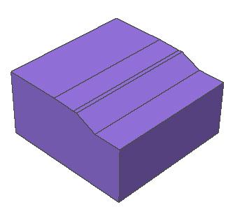
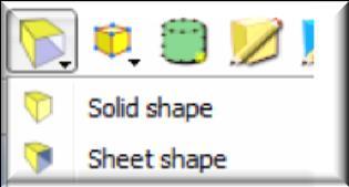
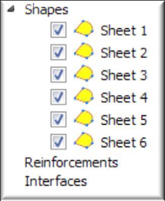
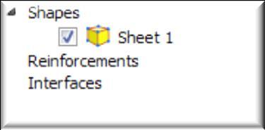
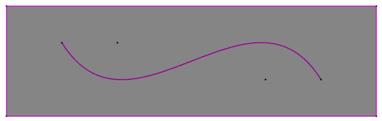
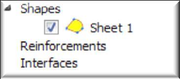
15 Shapes A shape is a collection of connected entities Four types of shapes: Solid body Sheet body Wire body Point body 15
 Shape (Cylinder)")
16 Shapes - Solid bodies Closed set of faces forms Solid volume vertex edge face Shape (Box) Shape (Cylinder) 16


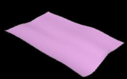
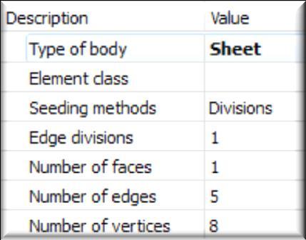
17 Shapes Sheet and Wire bodies Sheet Bodies 1 sheet body 1 face 5 edges 5 vertices 1 sheet body 2 faces 10 edges 9 vertices Wire Bodies 1 wire body 1 edge 2 vertices 1 wire body 3 edges 4 vertices 1 wire body 4 edges 4 vertices 1 sheet body 4 faces 12 edges 8 vertices 17
18 Geometry modelling Geometrical modelling functions: Import STEP/IGES file formats Primitives, basic shapes Move, Rotate, Scale Boolean operations Selection of points/lines/faces/bodies and operations Automatic clash detection Convert bodies and sheets Imprint points/lines on faces Rotate and move faces of a shape Extrude shapes Extract a sub-shape Align faces Many more 18


19 Modeling primitives 3D Import STEP/IGES file formats Import of CAD models Geometrical modelling based on Parasolid 19


20 Modeling primitives 3D solids Block Cylinder Cone Prism Torus Sphere 20


21 Modeling primitives 2D primitives 1D Polygonal sheet Circle sheet Line Circle Polyline Bezier curve Point 21


22 Modeling operations Boolean operations Unite Subtract Intersect Transformations Move Scale Rotate 22


23 Selection - Geometry parts Graphical selection of points, lines, surfaces and bodies 23


24 Modeling operations Automatic clash detection Edges of adjacent bodies and lines are automatically imprinted and considered in meshing 24


25 Modeling operations Sew two or more sheets Convert bodies and sheets 25


26 Modeling operations Imprint points and lines on surface 26

27 Modeling operations Rotate and move faces of a shape 27

28 Modeling operations Extract a sub-shape Extrude shapes Lines Faces 28
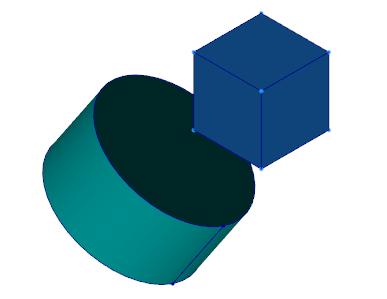
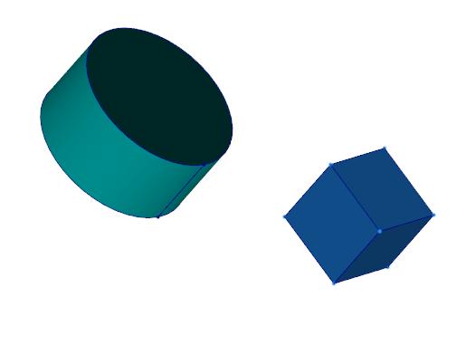
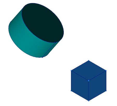
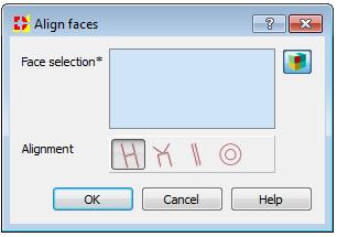
29 Modeling operations Align faces Coincident Co-planar Parallel Co-centric 29
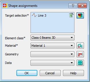
30 Model setup Property assignment Property assignment: Element-classes (Material, Geometry, Data) Reinforcements (Material, Geometry, Data) Interfaces (Material, Geometry, Data) Boundaries for heat-flow, groundwater analysis (Material) Supports (structural analysis) Loads acting on parts Loads acting on model Initial fields acting on parts 30

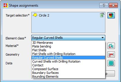
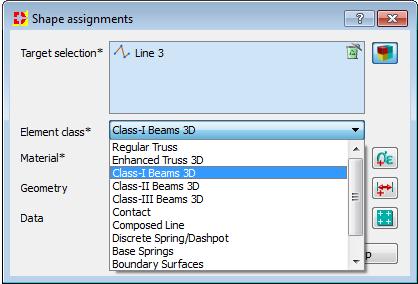
31 Model setup Property assignment Element classes 31

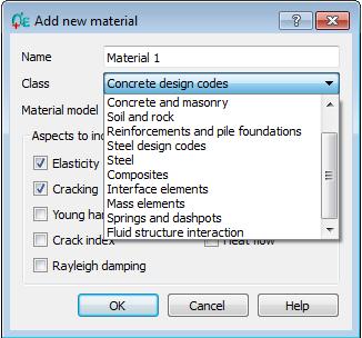
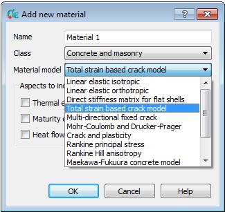
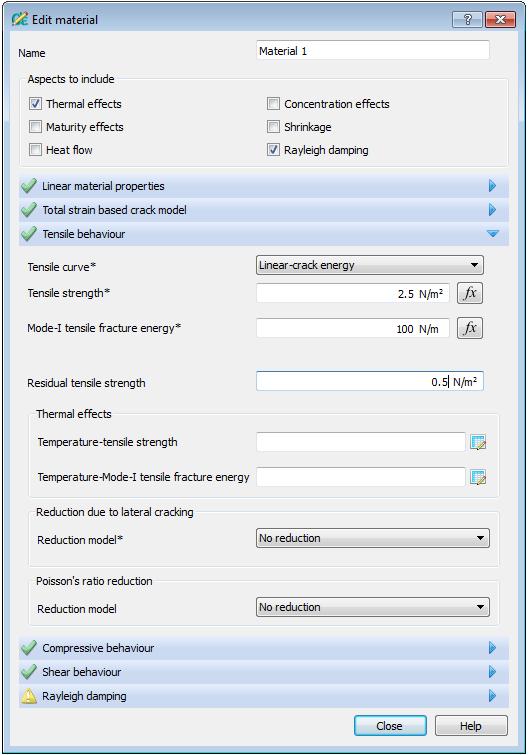
32 Model setup Property assignment Material classes 32

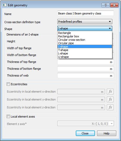
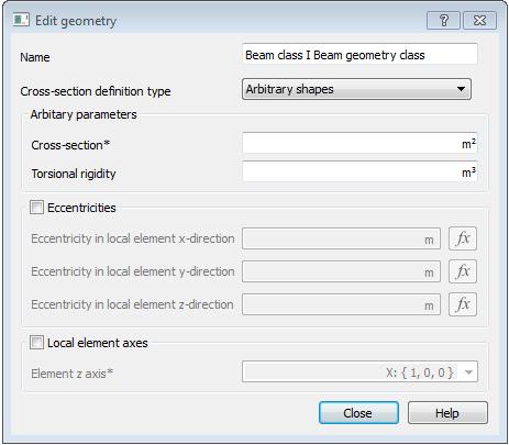
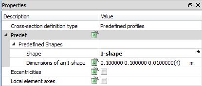
33 Model setup Property assignment Geometry classes 33


34 Model setup Property assignment Reinforcement classes Bodies Faces Faces Lines Lines Points 34
 Not connected (Deactivate clash detection continuum elements not")
35 Model setup Property assignment Interface classes Defined on sub-shapes Faces (2D) Edges (1D) Connected (Interface element between continuum elements) Boundary (Interface element between continuum element and supported edge/line) Not connected (Deactivate clash detection continuum elements not connected) 35


36 Model setup Boundary assignment Boundaries for thermal and groundwater flow analysis Heat Flow Prescribed temperature External temperature Radiative temperature Thermal flux Groundwater Flow Prescribed head External head Groundwater flux 36


37 Model setup Boundary assignment Supports for structural analysis On points, lines, faces and bodies In global and local coordinate-system Defined for all nodes related to selected part 37
38 Model setup Load assignment Loads acting on parts Type of loads Points Lines Faces Bodies Force X X X Moment X X X Prescribed Deformation Prescribed Acceleration Distributed Force X Distributed Moment X Hydrostatic Pressure X X Reinforcement Pre-stress X Reinforcement Post-tensioning X X X 38

39 Model setup Load assignment Loads acting on parts 39


40 Model setup Load assignment Loads acting on parts 40


41 Model setup Load assignment Loads acting on model Dead weight Equivalent acceleration Centrifugal load Base acceleration


42 Model setup Load assignment Initial fields Displacements Rotations Velocities Temperatures Heads 42
43 Meshing options Generate the mesh Seedings per body/line (divisions/element-size) In clashes the smallest element-size is applied Preview of seeding Linear or quadratic elements Automatic quad/hexa mesher or triangle/tetrahedron mesher Surface meshes are defined as structured meshes when possible Body meshes are not structured Reinforcements are embedded in mesh Interfaces are embedded in mesh Boundary elements are embedded in mesh 43


44 Meshing options Generate the mesh 44
45 Analysis setup Setup analysis Define analysis sequence Define analysis details via dialogues or property box Options for loading or saving.dcf files Run analysis Progress logging in GUI Option for running analysis in batch mode Error message refer graphically to model Logging selected analysis results in GUI Automatic import of results at the end of analysis Option for loading results manually 45

 Optional output in FX4D, idiana, original")
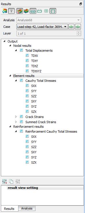
46 Post-processing features Checking results: Deformed models Contour-plots Iso-surfaces Clipping planes Diagrams Vectors Stress and strain tensor rosettes Cracks Tables, export to Excel Result view setting management (inc. saving the post-processing settings) Optional output in FX4D, idiana, original tabular format (.txt) 46
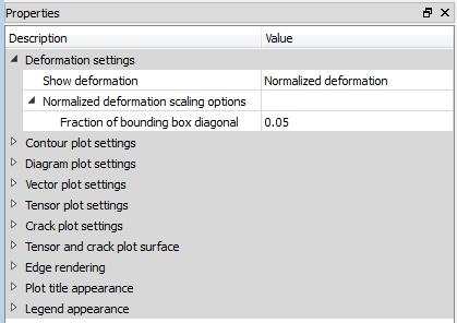
47 Post-processing features Deformed shape 47
48 Post-processing features Contour plot settings (iso-surfaces)


49 Post-processing features Contour plot settings (Clipping planes)

50 Post-processing features Contour plot settings (Clipping planes)

51 Post-processing features Contour plot settings (Clipping planes)


52 Post-processing features Contour plot settings (Clipping planes)

53 Post-processing features Contour plot settings
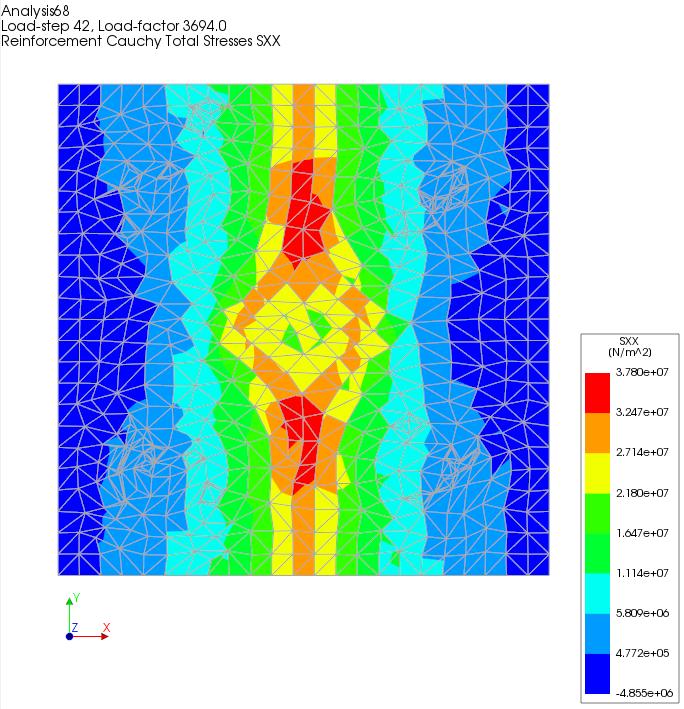
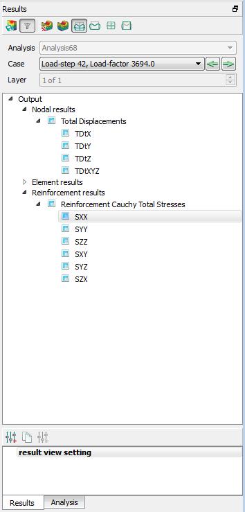
54 Post-processing features Reinforcements contours in grids
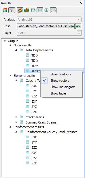
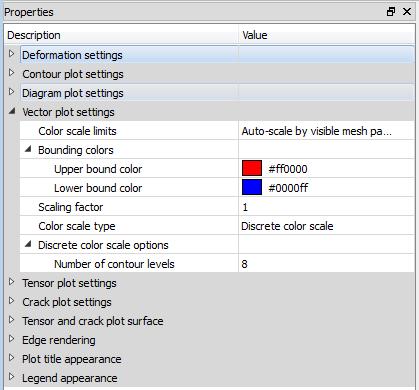
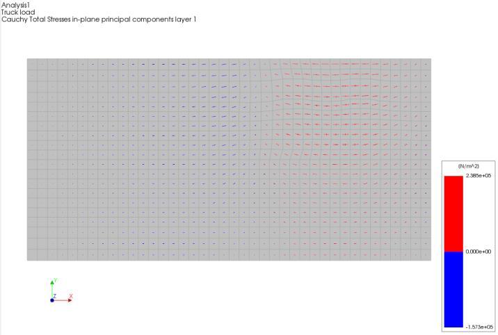
55 Post-processing features Vector plot settings
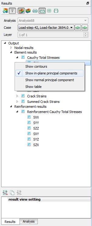
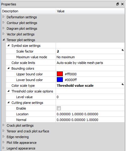
56 Post-processing features Tensor plot settings


57 Post-processing features Tensor plot settings (clipping plane)


58 Post-processing features Stress/strain normal to cutting plane
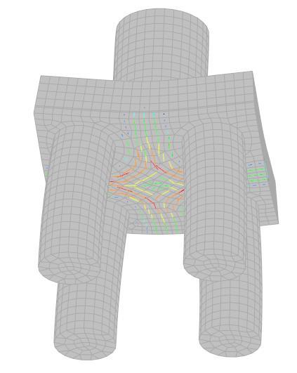
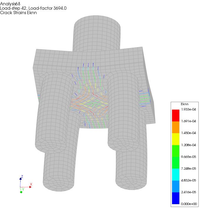
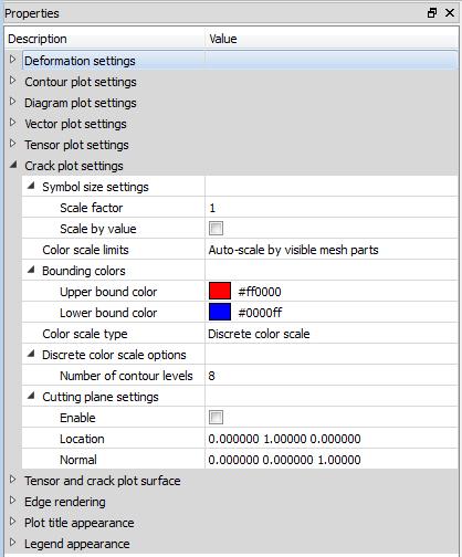
59 Post-processing features Crack plot settings
")
60 Post-processing features Crack plot settings (clipping plane)
")
61 Post-processing features Crack plot settings (clipping plane)
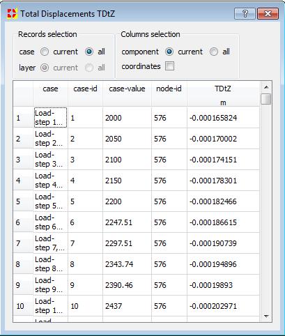

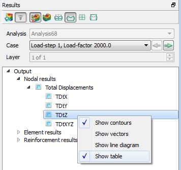
62 Post-processing features Tables Copy and paste to MS-Excel
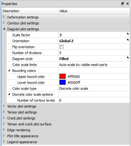
63 Post-processing features Diagram plot settings
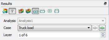
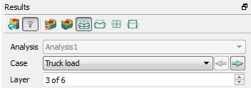

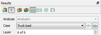
64 Post-processing features Layers in shell and beam elements
![Post-processing features Python scripting newproject( "Untitled", 100 ) setmodelanalysisaspects( [ "STRUCT" ] ) setmodeldimension( "3D" ) setdefaultmeshorder( "LINEAR" ) setdefaultmeshertype(](/docs-images/90/101405575/images/65-0.jpg "\"HEX_QUAD\" ) n = 4 m = 6 icnt = 0 for i in range( 0, n ): for j in range( 0, m ): icnt = icnt+1 name = \"Pile \" numb = '{0:6d}'.")
65 Post-processing features Python scripting newproject( "Untitled", 100 ) setmodelanalysisaspects( [ "STRUCT" ] ) setmodeldimension( "3D" ) setdefaultmeshorder( "LINEAR" ) setdefaultmeshertype( "HEX_QUAD" ) n = 4 m = 6 icnt = 0 for i in range( 0, n ): for j in range( 0, m ): icnt = icnt+1 name = "Pile " numb = '{0:6d}'.format(icnt) pilename = name + numb createblock( pilename, [ 2*i, 2*j, 1 ], [ 1, 1, 5 ] ) createblock( "Plate", [ 0, 0, 0 ], [ 2*(n-1)+1, 2*(m-1)+1, 1 ] ) > newproject( "Untitled", 100 ) > setmodelanalysisaspects( [ "STRUCT" ] ) > setmodeldimension( "3D" ) > setdefaultmeshorder( "LINEAR" ) > setdefaultmeshertype( "HEX_QUAD" ) > createblock( "Pile 1", [ 0, 0, 1 ], [ 1, 1, 5 ] ) > createblock( "Pile 2", [ 0, 2, 1 ], [ 1, 1, 5 ] ) > createblock( "Pile 3", [ 0, 4, 1 ], [ 1, 1, 5 ] ) > createblock( "Pile 4", [ 0, 6, 1 ], [ 1, 1, 5 ] ) > createblock( "Pile 5", [ 0, 8, 1 ], [ 1, 1, 5 ] ) > createblock( "Pile 6", [ 0, 10, 1 ], [ 1, 1, 5 ] ) > createblock( "Pile 7", [ 2, 0, 1 ], [ 1, 1, 5 ] ) > createblock( "Pile 8", [ 2, 2, 1 ], [ 1, 1, 5 ] ) > createblock( "Pile 9", [ 2, 4, 1 ], [ 1, 1, 5 ] ) > createblock( "Pile 10", [ 2, 6, 1 ], [ 1, 1, 5 ] ) > createblock( "Pile 11", [ 2, 8, 1 ], [ 1, 1, 5 ] ) > createblock( "Pile 12", [ 2, 10, 1 ], [ 1, 1, 5 ] ) > createblock( "Pile 13", [ 4, 0, 1 ], [ 1, 1, 5 ] ) > createblock( "Pile 14", [ 4, 2, 1 ], [ 1, 1, 5 ] ) > createblock( "Pile 15", [ 4, 4, 1 ], [ 1, 1, 5 ] ) > createblock( "Pile 16", [ 4, 6, 1 ], [ 1, 1, 5 ] ) > createblock( "Pile 17", [ 4, 8, 1 ], [ 1, 1, 5 ] ) > createblock( "Pile 18", [ 4, 10, 1 ], [ 1, 1, 5 ] ) > createblock( "Pile 19", [ 6, 0, 1 ], [ 1, 1, 5 ] ) > createblock( "Pile 20", [ 6, 2, 1 ], [ 1, 1, 5 ] ) > createblock( "Pile 21", [ 6, 4, 1 ], [ 1, 1, 5 ] ) > createblock( "Pile 22", [ 6, 6, 1 ], [ 1, 1, 5 ] ) > createblock( "Pile 23", [ 6, 8, 1 ], [ 1, 1, 5 ] ) > createblock( "Pile 24", [ 6, 10, 1 ], [ 1, 1, 5 ] ) > createblock( "Plate", [ 0, 0, 0 ], [ 7, 11, 1 ] )
66 TNO DIANA BV (Head Office) Delftechpark 19a 2628 XJ Delft The Netherlands T +31 (0) F +31 (0) TNO DIANA BV (Engineering Division) Engineering (TD/E) Vlamoven TN Arnhem The Netherlands T +31 (0) TNO DIANA UK Ltd Ground Floor Building 1000 Lakeside North Harbour Western Road Portsmouth PO6 3EZ United Kingdom T +44 (0) F +44 (0) TNO DIANA North America Inc Seven Mile Road Suite 260 MI Livonia T +1 (0)
DIANA 10 Finite Element Analysis. Civil Engineering Geotechnical Engineering Petroleum Engineering
 DIANA 10 Finite Element Analysis Civil Engineering Geotechnical Engineering Petroleum Engineering History of TNO DIANA 1972 TNO Department of Computational Mechanics 1975 Start of DIANA (Displacement ANAlyzer)
Customized Pre/post-processor for DIANA. FX for DIANA
 Customized Pre/post-processor for DIANA FX for DIANA About FX4D for DIANA FX4D is a general purpose pre/post-processor for CAE simulation. FX4D has been specialized for civil/architectural applications.
DIANA FINITE ELEMENT ANALYSIS
 DIANA FINITE ELEMENT ANALYSIS DIANA FEA a TNO Company DIANA F I N I T E E L E M E N T A N A LY S I S DIANA (DIsplacement ANAlyzer) is a multi-purpose finite element program, with a special strength in
In-plane principal stress output in DIANA
 analys: linear static. class: large. constr: suppor. elemen: hx24l solid tp18l. load: edge elemen force node. materi: elasti isotro. option: direct. result: cauchy displa princi stress total. In-plane
Linear Analysis of an Arch Dam
 Linear Analysis of an Arch Dam Outline 1 Description 2 Finite Element Model 2.1 Coincidence Tolerance 2.2 Units 2.3 Import CAD File 2.4 Properties 2.5 Boundary Conditions 2.6 Loads 2.7 Meshing 3 Linear
Outline. 3 Linear Analysis 3.1 Analysis commands 3.2 Results. Box Girder Bridge 2/28
 ANALYS: linear static. CONSTR: suppor. ELEMEN: bar hx24l reinfo solid tp18l. LOAD: elemen face force prestr reinfo weight. MATERI: elasti isotro. OPTION: direct. POST: binary ndiana. PRE: dianai. RESULT:
Elastic Analysis of a Deep Beam with Web Opening
 Elastic Analysis of a Deep Beam with Web Opening Outline 1 Description 2 Finite Element Model 2.1 Units 2.2 Geometry definition 2.3 Properties 2.4 Boundary conditions 2.4.1 Constraints 2.4.2 Vertical load
Report Generation. Name: Path: Keywords:
 Report Generation Name: Path: Keywords: ReportGeneration/repgen /Examples//ReportGeneration/repgen analys: eigen geomet nonlin physic. constr: suppor. elemen: beam class2 curved interf l13be q20sh q24if
Fluid Structure Interaction - Moving Wall in Still Water
 Fluid Structure Interaction - Moving Wall in Still Water Outline 1 Problem description 2 Methodology 2.1 Modelling 2.2 Analysis 3 Finite Element Model 3.1 Project settings 3.2 Units 3.3 Geometry Definition
Geometry Definition in the ADINA User Interface (AUI) Daniel Jose Payen, Ph.D. March 7, 2016
 Daniel Jose Payen, Ph.D. March 7, 2016") Geometry Definition in the ADINA User Interface (AUI) Daniel Jose Payen, Ph.D. March 7, 2016 ADINA R&D, Inc., 2016 1 Topics Presented ADINA에서쓰이는 Geometry 종류 Simple (AUI) geometry ADINA-M geometry ADINA-M
Geometry Definition in the ADINA User Interface (AUI) Daniel Jose Payen, Ph.D. March 7, 2016 ADINA R&D, Inc., 2016 1 Topics Presented ADINA에서쓰이는 Geometry 종류 Simple (AUI) geometry ADINA-M geometry ADINA-M
Elastic Analysis of a Bending Plate
 analys: linear static. constr: suppor. elemen: plate q12pl. load: elemen face force. materi: elasti isotro. option: direct units. post: binary ndiana. pre: dianai. result: cauchy displa extern force green
Advanced Webinar. Date: December 8, 2011 Topic: General Use of midas GTS (Part I) Presenter: Abid Ali, Geotechnical Engineer
 Presenter: Abid Ali, Geotechnical Engineer") midas GTS Advanced Webinar Date: December 8, 2011 Topic: General Use of midas GTS (Part I) Presenter: Abid Ali, Geotechnical Engineer Bridging Your Innovations to Realities Contents: 1. Introduction 2.
midas GTS Advanced Webinar Date: December 8, 2011 Topic: General Use of midas GTS (Part I) Presenter: Abid Ali, Geotechnical Engineer Bridging Your Innovations to Realities Contents: 1. Introduction 2.
Settlement Analysis of a Strip Footing Linear Static Analysis (Benchmark Example)
") Settlement Analysis of a Strip Footing Linear Static Analysis (Benchmark Example) analys: linear static. constr: suppor. elemen: ct12e pstrai. load: edge elemen force. materi: elasti isotro porosi. option:
Settlement Analysis of a Strip Footing Linear Static Analysis (Benchmark Example) analys: linear static. constr: suppor. elemen: ct12e pstrai. load: edge elemen force. materi: elasti isotro porosi. option:
GTS. midas GTS Advanced Webinar. Date: June 5, 2012 Topic: General Use of midas GTS (Part II) Presenter: Vipul Kumar
 Presenter: Vipul Kumar") midas GTS Advanced Webinar Date: June 5, 2012 Topic: General Use of midas GTS (Part II) Presenter: Vipul Kumar Bridging Your Innovations to Realities GTS MIDAS Information Technology Co., Ltd. [1/30] Contents:
midas GTS Advanced Webinar Date: June 5, 2012 Topic: General Use of midas GTS (Part II) Presenter: Vipul Kumar Bridging Your Innovations to Realities GTS MIDAS Information Technology Co., Ltd. [1/30] Contents:
Prescribed Deformations
 u Prescribed Deformations Outline 1 Description 2 Finite Element Model 2.1 Geometry Definition 2.2 Properties 2.3 Boundary Conditions 2.3.1 Constraints 2.3.2 Prescribed Deformation 2.4 Loads 2.4.1 Dead
GTS NX INTERFACES AUTOCAD MIDAS GEN FOR TUNNEL SOIL PILE INTERACTION ANALYSIS
 INTERFACES AUTOCAD MIDAS GEN FOR TUNNEL SOIL PILE INTERACTION ANALYSIS Angel F. Martinez Civil Engineer MIDASOFT Integrated Solver Optimized for the next generation 64-bit platform Finite Element Solutions
Reinforced concrete beam under static load: simulation of an experimental test
 Reinforced concrete beam under static load: simulation of an experimental test analys: nonlin physic. constr: suppor. elemen: bar cl12i cl3cm compos cq16m interf pstres reinfo struct. load: deform weight.
NEi FEA. IRONCAD Advanced FEA. IRONCAD Advanced FEA. NEi FEA
 2011 Overview has been designed as a universal, adaptive and user-friendly graphical user interface for geometrical modeling, data input and visualization of results for all types of numerical simulation
Engineering Drawing II
 Instructional Unit Basic Shading and Rendering -Basic Shading -Students will be able -Demonstrate the ability Class Discussions 3.1.12.B, -Basic Rendering to shade a 3D model to apply shading to a 3D 3.2.12.C,
Introduction: RS 3 Tutorial 1 Quick Start
 Introduction: RS 3 Tutorial 1 Quick Start Welcome to RS 3. This tutorial introduces some basic features of RS 3. The model analyzes the effect of tank loading on an existing sloped underground tunnel.
Version 4.1 Demo. RecurDynTM 2002 RecurDyn User Conference
 Version 4.1 Demo RecurDynTM 2002 RecurDyn User Conference What s New? Using Parasolid Kernel Solid Modeler Other Program Interfaces New Data Structure New & Improved Features What s New? Using Parasolid
Buckling Analysis of a Thin Plate
 Buckling Analysis of a Thin Plate Outline 1 Description 2 Modeling approach 3 Finite Element Model 3.1 Units 3.2 Geometry definition 3.3 Properties 3.4 Boundary conditions 3.5 Loads 3.6 Meshing 4 Structural
Autodesk Inventor 2019 and Engineering Graphics
 Autodesk Inventor 2019 and Engineering Graphics An Integrated Approach Randy H. Shih SDC PUBLICATIONS Better Textbooks. Lower Prices. www.sdcpublications.com Powered by TCPDF (www.tcpdf.org) Visit the
PTC Creo Simulate. Features and Specifications. Data Sheet
 PTC Creo Simulate PTC Creo Simulate gives designers and engineers the power to evaluate structural and thermal product performance on your digital model before resorting to costly, time-consuming physical
Convergent Modeling and Reverse Engineering
 Convergent Modeling and Reverse Engineering 25 October 2017 Realize innovation. Tod Parrella NX Design Product Management Product Engineering Solutions tod.parrella@siemens.com Realize innovation. Siemens
3D Soil Modelling (Geometry)
") 3D Soil Modelling (Geometry) Soil Profiling1 Description: This step shows how to import bolehole log data from a spreadsheet into GTS in preparation of soil modelling. Step 1. 1. Open GTS.exe 2. Main Menu:
3D Soil Modelling (Geometry) Soil Profiling1 Description: This step shows how to import bolehole log data from a spreadsheet into GTS in preparation of soil modelling. Step 1. 1. Open GTS.exe 2. Main Menu:
Lateral Loading of Suction Pile in 3D
 Lateral Loading of Suction Pile in 3D Buoy Chain Sea Bed Suction Pile Integrated Solver Optimized for the next generation 64-bit platform Finite Element Solutions for Geotechnical Engineering 00 Overview
Finite Element Analysis using ANSYS Mechanical APDL & ANSYS Workbench
 Finite Element Analysis using ANSYS Mechanical APDL & ANSYS Workbench Course Curriculum (Duration: 120 Hrs.) Section I: ANSYS Mechanical APDL Chapter 1: Before you start using ANSYS a. Introduction to
3D Excavation by Tunnel Boring Machine
 3D Excavation by Tunnel Boring Machine Angel Francisco Martinez Application Engineer MIDAS NY Content 01 Introduction 02 Advantages of GTS NX for Tunneling 03 TBM Demo Introduction About MIDAS No. 1 in
Introduction to ANSYS DesignModeler
 Lecture 5 Modeling 14. 5 Release Introduction to ANSYS DesignModeler 2012 ANSYS, Inc. November 20, 2012 1 Release 14.5 Preprocessing Workflow Geometry Creation OR Geometry Import Geometry Operations Meshing
Training Course Content
 Pioneering engineering software systems, support & services. Training Course Content 29800 Middlebelt Road Suite 100 Farmington Hills, MI 48334 United States of America Tel: +1 248 737 9760 Fax: +1 248
SimLab Release Notes. 1 A l t a i r E n g i n e e r i n g
 SimLab 11.0 Release Notes 1 A l t a i r E n g i n e e r i n g System Support extended to load and save GDA/SLB files of size greater than 4GB. Memory allocation is enhanced to support large models. Kubrix
SOLIDWORKS 2016 and Engineering Graphics
 SOLIDWORKS 2016 and Engineering Graphics An Integrated Approach Randy H. Shih SDC PUBLICATIONS Better Textbooks. Lower Prices. www.sdcpublications.com Powered by TCPDF (www.tcpdf.org) Visit the following
Linear Static Analysis of a Cantilever Beam
 Linear Static Analysis of a Cantilever Beam Outline 1 Theory 2 Finite Element Model 2.1 Units 2.2 Geometry Definition 2.3 Properties 2.4 Boundary Conditions 2.5 Loads 2.6 Meshing 3 Linear Static Analysis
TABLE OF CONTENTS WHAT IS ADVANCE DESIGN? INSTALLING ADVANCE DESIGN... 8 System requirements... 8 Advance Design installation...
 Starting Guide 2019 TABLE OF CONTENTS INTRODUCTION... 5 Welcome to Advance Design... 5 About this guide... 6 Where to find information?... 6 Contacting technical support... 6 WHAT IS ADVANCE DESIGN?...
SimLab 14.3 Release Notes
 SimLab 14.3 Release Notes Highlights SimLab 14.0 introduced new graphical user interface and since then this has evolved continuously in subsequent versions. In addition, many new core features have been
pre- & post-processing f o r p o w e r t r a i n
 pre- & post-processing f o r p o w e r t r a i n www.beta-cae.com With its complete solutions for meshing, assembly, contacts definition and boundary conditions setup, ANSA becomes the most efficient and
Customisation and Automation using the LUSAS Programmable Interface (LPI)
") Customisation and Automation using the LUSAS Programmable Interface (LPI) LUSAS Programmable Interface The LUSAS Programmable Interface (LPI) allows the customisation and automation of modelling and results
Customisation and Automation using the LUSAS Programmable Interface (LPI) LUSAS Programmable Interface The LUSAS Programmable Interface (LPI) allows the customisation and automation of modelling and results
ANSYS Workbench Guide
 ANSYS Workbench Guide Introduction This document serves as a step-by-step guide for conducting a Finite Element Analysis (FEA) using ANSYS Workbench. It will cover the use of the simulation package through
SimWise. 3D Dynamic Motion, and Stress Analysis. integrated with Alibre Design
 SimWise 3D Dynamic Motion, and Stress Analysis integrated with Alibre Design SimWise 4D for Alibre Integrated Motion Simulation and Stress Analysis SimWise 4D is a software tool that allows the functional
Eurocodes and Innovation. Developments in Finite Element Analysis for Bridges
 Eurocodes and Innovation Developments in Finite Element Analysis for Bridges Developments in Finite Element Analysis for Bridges Ease of Use Vehicle Loading - Autocombinations Cable Tuning Construction
Outline. COMSOL Multyphysics: Overview of software package and capabilities
 COMSOL Multyphysics: Overview of software package and capabilities Lecture 5 Special Topics: Device Modeling Outline Basic concepts and modeling paradigm Overview of capabilities Steps in setting-up a
EN1740 Computer Aided Visualization and Design Spring /26/2012 Brian C. P. Burke
 EN1740 Computer Aided Visualization and Design Spring 2012 4/26/2012 Brian C. P. Burke Last time: More motion analysis with Pro/E Tonight: Introduction to external analysis products ABAQUS External Analysis
3. Preprocessing of ABAQUS/CAE
 3.1 Create new model database 3. Preprocessing of ABAQUS/CAE A finite element analysis in ABAQUS/CAE starts from create new model database in the toolbar. Then save it with a name user defined. To build
ANSYS AIM 16.0 Overview. AIM Program Management
 1 2015 ANSYS, Inc. September 27, 2015 ANSYS AIM 16.0 Overview AIM Program Management 2 2015 ANSYS, Inc. September 27, 2015 Today s Simulation Challenges Leveraging simulation across engineering organizations
Analysis Steps 1. Start Abaqus and choose to create a new model database
 Source: Online tutorials for ABAQUS Problem Description The two dimensional bridge structure, which consists of steel T sections (b=0.25, h=0.25, I=0.125, t f =t w =0.05), is simply supported at its lower
midas Civil Advanced Webinar Date: February 9th, 2012 Topic: General Use of midas Civil Presenter: Abhishek Das Bridging Your Innovations to Realities
 Advanced Webinar Date: February 9th, 2012 Topic: General Use of midas Civil Presenter: Abhishek Das Contents: Overview Modeling Boundary Conditions Loading Analysis Results Design and Misc. Introduction
Slope Stability of Open Pit Mine in 2D & 3D
 Slope Stability of Open Pit Mine in D & D MIDASoft Inc. Angel Francisco Martinez Civil Engineer Email : a.martinez@midasit.com Integrated Solver Optimized for the next generation64-bit platform Finite
Solid Modelling. Graphics Systems / Computer Graphics and Interfaces COLLEGE OF ENGINEERING UNIVERSITY OF PORTO
 Solid Modelling Graphics Systems / Computer Graphics and Interfaces 1 Solid Modelling In 2D, one set 2D line segments or curves does not necessarily form a closed area. In 3D, a collection of surfaces
SOLIDWORKS Flow Simulation Options
 SOLIDWORKS Flow Simulation Options SOLIDWORKS Flow Simulation includes an options dialogue window that allows for defining default options to use for a new project. Some of the options included are unit
FEMAP All Rights Reserved NASTRAN 1
 FEMAP 1 Overview Femap V10.3 is a Windows-native pre- and postprocessor used by engineering organizations world wide to model various products, processes, and systems. Its graphical user interface provides
Lecture 3 : General Preprocessing. Introduction to ANSYS Mechanical Release ANSYS, Inc. February 27, 2015
 Lecture 3 : General Preprocessing 16.0 Release Introduction to ANSYS Mechanical 1 2015 ANSYS, Inc. February 27, 2015 Chapter Overview In this chapter we cover basic preprocessing operations that are common
Oasys Pdisp. Copyright Oasys 2013
 Oasys Pdisp Copyright Oasys 2013 All rights reserved. No parts of this work may be reproduced in any form or by any means - graphic, electronic, or mechanical, including photocopying, recording, taping,
ECE421: Electronics for Instrumentation
 ECE421: Electronics for Instrumentation Lecture #8: Introduction to FEA & ANSYS Mostafa Soliman, Ph.D. March 23 rd 2015 Mostafa Soliman, Ph.D. 1 Outline Introduction to Finite Element Analysis Introduction
FEMAP FEMAP Modeler. Meshing: Subdivision and semi-automatic meshing of solids Automatic and mapped meshing (with quads or bricks), including biasing
, including biasing") FEMAP FEMAP Modeler Overview FEMAP V9.3 is a Windows-native pre- and post-processor used by engineering organizations world wide to model various products, processes, and systems. Its graphical user interface
FEMAP FEMAP Modeler Overview FEMAP V9.3 is a Windows-native pre- and post-processor used by engineering organizations world wide to model various products, processes, and systems. Its graphical user interface
Metafor FE Software. 2. Operator split. 4. Rezoning methods 5. Contact with friction
 ALE simulations ua sus using Metafor eao 1. Introduction 2. Operator split 3. Convection schemes 4. Rezoning methods 5. Contact with friction 1 Introduction EULERIAN FORMALISM Undistorted mesh Ideal for
Appendix S. ESATAN Thermal Modelling Suite Product Developments and Demonstration. Chris Kirtley Nicolas Bures (ITP Engines UK Ltd, United Kingdom)
") 249 Appendix S ESATAN Thermal Modelling Suite Product Developments and Demonstration Chris Kirtley Nicolas Bures (ITP Engines UK Ltd, United Kingdom) 250 ESATAN Thermal Modelling Suite Product Developments
249 Appendix S ESATAN Thermal Modelling Suite Product Developments and Demonstration Chris Kirtley Nicolas Bures (ITP Engines UK Ltd, United Kingdom) 250 ESATAN Thermal Modelling Suite Product Developments
PTC Newsletter January 14th, 2002
 PTC Email Newsletter January 14th, 2002 PTC Product Focus: Pro/MECHANICA (Structure) Tip of the Week: Creating and using Rigid Connections Upcoming Events and Training Class Schedules PTC Product Focus:
SolidWorks 2013 and Engineering Graphics
 SolidWorks 2013 and Engineering Graphics An Integrated Approach Randy H. Shih SDC PUBLICATIONS Schroff Development Corporation Better Textbooks. Lower Prices. www.sdcpublications.com Visit the following
SimWise 4D. Integrated Motion and Stress Analysis
 SimWise 4D Integrated Motion and Stress Analysis SimWise 4D Integrated Motion Simulation and Stress Analysis SimWise 4D is a software tool that allows the functional performance of mechanical parts and
FOUNDATION IN OVERCONSOLIDATED CLAY
 1 FOUNDATION IN OVERCONSOLIDATED CLAY In this chapter a first application of PLAXIS 3D is considered, namely the settlement of a foundation in clay. This is the first step in becoming familiar with the
Parametric Modeling Design and Modeling 2011 Project Lead The Way, Inc.
 Parametric Modeling Design and Modeling 2011 Project Lead The Way, Inc. 3D Modeling Steps - Sketch Step 1 Sketch Geometry Sketch Geometry Line Sketch Tool 3D Modeling Steps - Constrain Step 1 Sketch Geometry
Lesson 5 Solid Modeling - Constructive Solid Geometry
 AutoCAD 2000i Tutorial 5-1 Lesson 5 Solid Modeling - Constructive Solid Geometry Understand the Constructive Solid Geometry Concept. Create a Binary Tree. Understand the basic Boolean Operations. Create
Introduction to ANSYS DesignModeler
 Lecture 9 Beams and Shells 14. 5 Release Introduction to ANSYS DesignModeler 2012 ANSYS, Inc. November 20, 2012 1 Release 14.5 Beams & Shells The features in the Concept menu are used to create and modify
Table of Contents Memory Management... 3 Results Enveloping... 5 Set Random Property Colors... 8 Model Box Extend Merge Mesh...
 1 Table of Contents Memory Management... 3 Results Enveloping... 5 Set Random Property Colors... 8 Model Box... 11 Extend Merge Mesh... 13 NonManifold Add... 16 Element Visual Inspection... 18 Graphical
2: Static analysis of a plate
 2: Static analysis of a plate Topics covered Project description Using SolidWorks Simulation interface Linear static analysis with solid elements Finding reaction forces Controlling discretization errors
CE366/ME380 Finite Elements in Applied Mechanics I Fall 2007
 CE366/ME380 Finite Elements in Applied Mechanics I Fall 2007 FE Project 1: 2D Plane Stress Analysis of acantilever Beam (Due date =TBD) Figure 1 shows a cantilever beam that is subjected to a concentrated
equivalent stress to the yield stess.
 Example 10.2-1 [Ansys Workbench/Thermal Stress and User Defined Result] A 50m long deck sitting on superstructures that sit on top of substructures is modeled by a box shape of size 20 x 5 x 50 m 3. It
Physically-Based Modeling and Animation. University of Missouri at Columbia
 Overview of Geometric Modeling Overview 3D Shape Primitives: Points Vertices. Curves Lines, polylines, curves. Surfaces Triangle meshes, splines, subdivision surfaces, implicit surfaces, particles. Solids
Introduction to ANSYS
 Lecture 1 Introduction to ANSYS ICEM CFD 14. 0 Release Introduction to ANSYS ICEM CFD 1 2011 ANSYS, Inc. March 22, 2015 Purpose/Goals Ansys ICEM CFD is a general purpose grid generating program Grids for
Case Study 2: Piezoelectric Circular Plate
 Case Study 2: Piezoelectric Circular Plate PROBLEM - 3D Circular Plate, kp Mode, PZT4, D=50mm x h=1mm GOAL Evaluate the operation of a piezoelectric circular plate having electrodes in the top and bottom
Introduction to the Finite Element Method (3)
") Introduction to the Finite Element Method (3) Petr Kabele Czech Technical University in Prague Faculty of Civil Engineering Czech Republic petr.kabele@fsv.cvut.cz people.fsv.cvut.cz/~pkabele 1 Outline
Introduction to the Finite Element Method (3) Petr Kabele Czech Technical University in Prague Faculty of Civil Engineering Czech Republic petr.kabele@fsv.cvut.cz people.fsv.cvut.cz/~pkabele 1 Outline
CHAPTER 4. Numerical Models. descriptions of the boundary conditions, element types, validation, and the force
 CHAPTER 4 Numerical Models This chapter presents the development of numerical models for sandwich beams/plates subjected to four-point bending and the hydromat test system. Detailed descriptions of the
Introduction to ANSYS ICEM CFD
 Lecture 1 Introduction to ANSYS ICEM CFD 14.5 Release Introduction to ANSYS ICEM CFD 2012 ANSYS, Inc. April 1, 2013 1 Release 14.5 Purpose/Goals Ansys ICEM CFD is a general purpose grid generating program
SETTLEMENT OF A CIRCULAR FOOTING ON SAND
 1 SETTLEMENT OF A CIRCULAR FOOTING ON SAND In this chapter a first application is considered, namely the settlement of a circular foundation footing on sand. This is the first step in becoming familiar
Overview of ABAQUS II. Working with Geometry in ABAQUS III. Working with models Created Outside ABAQUS IV. Material and Section Properties
 ABAQUS TRAINING I. Overview of ABAQUS II. Working with Geometry in ABAQUS III. Working with models Created Outside ABAQUS IV. Material and Section Properties V. Assemblies in ABAQUS VI. Steps, Output,
Lesson 2 Constructive Solid Geometry Concept. Parametric Modeling with I-DEAS 2-1
 Lesson 2 Constructive Solid Geometry Concept Parametric Modeling with I-DEAS 2-1 2-2 Parametric Modeling with I-DEAS Introduction In the 1980s, one of the main advancements in Solid Modeling was the development
Geometric Modeling. Introduction
 Geometric Modeling Introduction Geometric modeling is as important to CAD as governing equilibrium equations to classical engineering fields as mechanics and thermal fluids. intelligent decision on the
ACP (ANSYS Composite Prep/Post) Jim Kosloski
 Jim Kosloski") ACP (ANSYS Composite Prep/Post) Jim Kosloski ACP Background ANSYS Composite PrepPost is an add-on module dedicated to the modeling of layered composite structures. ACP is now included with the Mechanical
ACP (ANSYS Composite Prep/Post) Jim Kosloski ACP Background ANSYS Composite PrepPost is an add-on module dedicated to the modeling of layered composite structures. ACP is now included with the Mechanical
SolidWorks. An Overview of SolidWorks and Its Associated Analysis Programs
 An Overview of SolidWorks and Its Associated Analysis Programs prepared by Prof. D. Xue University of Calgary SolidWorks - a solid modeling CAD tool. COSMOSWorks - a design analysis system fully integrated
INTRODUCTION TO THE SYSTEM
 INTRODUCTION TO THE SYSTEM 1 INTRODUCTION TO THE SYSTEM 1. Introduction The ANSYS computer program is a large-scale multi-purpose finite element program, which may be used for solving several classes of
Modeling 3D Objects: Part 2
 Modeling 3D Objects: Part 2 Patches, NURBS, Solids Modeling, Spatial Subdivisioning, and Implicit Functions 3D Computer Graphics by Alan Watt Third Edition, Pearson Education Limited, 2000 General Modeling
ADAPT-Builder. Toolbar Descriptions Updated November Copyright All rights reserved 2017
 ADAPT-Builder Toolbar Descriptions Updated November 2017 Copyright All rights reserved 2017 Main Toolbar The Main Toolbar is where the typical functions that are in most programs such as New, Open, Save,
Creo Simulate 3.0 Tutorial
 Creo Simulate 3.0 Tutorial Structure and Thermal Roger Toogood, Ph.D., P. Eng. SDC PUBLICATIONS Better Textbooks. Lower Prices. www.sdcpublications.com Powered by TCPDF (www.tcpdf.org) Visit the following
1 Classification of Shell Forms
 Proceedings of the 5 th International Conference on Computation of Shell and Spatial Structures June 1-4, 2005 Salzburg, Austria E. Ramm, W.A. Wall, K.-U. Bletzinger, M. Bischoff (eds.) www.iassiacm2005.de
AutoCAD 2013 Tutorial - Second Level: 3D Modeling
 AutoCAD 2013 Tutorial - Second Level: 3D Modeling Randy H. Shih SDC PUBLICATIONS Schroff Development Corporation Better Textbooks. Lower Prices. www.sdcpublications.com Visit the following websites to
Workshop 15. Single Pass Rolling of a Thick Plate
 Introduction Workshop 15 Single Pass Rolling of a Thick Plate Rolling is a basic manufacturing technique used to transform preformed shapes into a form suitable for further processing. The rolling process
midas FEA V320 Table of Contents
 midas FEA V320 New Feature 01 CFD Moving Mesh Pre Process 01 File Open > File Preview 02 Extract Surface 03 Frame to Solid > Import 04 Tetra Auto mesh generation 05 Mesh options 06 Auto mesh Solid Function
Lecture overview. Visualisatie BMT. Vector algorithms. Vector algorithms. Time animation. Time animation
 Visualisatie BMT Lecture overview Vector algorithms Tensor algorithms Modeling algorithms Algorithms - 2 Arjan Kok a.j.f.kok@tue.nl 1 2 Vector algorithms Vector 2 or 3 dimensional representation of direction
ATENA Program Documentation Part 4-2. Tutorial for Program ATENA 3D. Written by: Jan Červenka, Zdenka Procházková, Tereza Sajdlová
 Červenka Consulting s.ro. Na Hrebenkach 55 150 00 Prague Czech Republic Phone: +420 220 610 018 E-mail: cervenka@cervenka.cz Web: http://www.cervenka.cz ATENA Program Documentation Part 4-2 Tutorial for
Femap Version
 Femap Version 11.3 Benefits Easier model viewing and handling Faster connection definition and setup Faster and easier mesh refinement process More accurate meshes with minimal triangle element creation
Deep Beam With Web Opening
 Deep Beam With Web Opening Name: Path: Keywords: DeepBeamWithWebOpening/deepbeam /Examples//DeepBeamWithWebOpening/deepbeam analys: linear static. constr: suppor. elemen: cq16m ct12m pstres. load: force
Chapter 2: Rhino Objects
 The fundamental geometric objects in Rhino are points, curves, surfaces, polysurfaces, extrusion objects, and polygon mesh objects. Why NURBS modeling NURBS (non-uniform rational B-splines) are mathematical
RhinoCFD Tutorial. Flow Past a Sphere
 RhinoCFD Tutorial Flow Past a Sphere RhinoCFD Ocial document produced by CHAM September 26, 2017 Introduction Flow Past a Sphere This tutorial will describe a simple calculation of ow around a sphere and
COMPUTER AIDED ARCHITECTURAL GRAPHICS FFD 201/Fall 2013 HAND OUT 1 : INTRODUCTION TO 3D
 COMPUTER AIDED ARCHITECTURAL GRAPHICS FFD 201/Fall 2013 INSTRUCTORS E-MAIL ADDRESS OFFICE HOURS Özgür Genca ozgurgenca@gmail.com part time Tuba Doğu tubadogu@gmail.com part time Şebnem Yanç Demirkan sebnem.demirkan@gmail.com
World-class finite element analysis (FEA) solution for the Windows desktop
 solution for the Windows desktop") World-class finite element analysis (FEA) solution for the Windows desktop fact sheet Siemens PLM Software www.siemens.com/plm/femap Summary Femap software is an advanced engineering analysis environment
World-class finite element analysis (FEA) solution for the Windows desktop fact sheet Siemens PLM Software www.siemens.com/plm/femap Summary Femap software is an advanced engineering analysis environment
3D Finite Element Software for Cracks. Version 3.2. Benchmarks and Validation
 3D Finite Element Software for Cracks Version 3.2 Benchmarks and Validation October 217 1965 57 th Court North, Suite 1 Boulder, CO 831 Main: (33) 415-1475 www.questintegrity.com http://www.questintegrity.com/software-products/feacrack
Geometric Modeling Topics
 Geometric Modeling Topics George Allen, george.allen@siemens.com Outline General background Convergent modeling Multi-material objects Giga-face lattices Page 2 Boundary Representation (b-rep) Topology
Chapter 5 Modeling and Simulation of Mechanism
 Chapter 5 Modeling and Simulation of Mechanism In the present study, KED analysis of four bar planar mechanism using MATLAB program and ANSYS software has been carried out. The analysis has also been carried
Simcenter 3D Engineering Desktop
 Simcenter 3D Engineering Desktop Integrating geometry and FE modeling to streamline the product development process Benefits Speed simulation processes by up to 70 percent Increase product quality by rapidly