MENG 372 Chapter 3 Graphical Linkage Synthesis. All figures taken from Design of Machinery, 3 rd ed. Robert Norton 2003
|
|
|
- Ruth Jackson
- 5 years ago
- Views:
Transcription
1 MENG 372 Chapter 3 Graphical Linkage Synthesis All figures taken from Design of Machinery, 3 rd ed. Robert Norton
2 Introduction Synthesis: to design or create a mechanism to give a certain motion Analysis: to determine the motion characteristics of a given mechanism 2
3 Function, Path, & Motion Generation Function Generation: correlation of an input motion with an output motion in a mechanism Path Generation: control of a point in a plane such that it follows some prescribed path Motion Generation: the control of a line in a plane such that it assumes some prescribed set of sequential positions Planar vs. Spatial Mechanisms: many spatial mechanisms duplicate planar mechanisms 3
4 Limiting Conditions (Toggle) Toggle: a point where the link cannot rotate anymore. Determined by the colinearity of two moving links. Need to check when making a design (either by making a cardboard model or working model). 4

5 Limiting Conditions (Toggle) Landing gear 5
6 Limiting Conditions Transmission angle (µ): the absolute value of the acute angle of the pair of angles at the intersection of the two links. Want the force in link 3 to rotate link 4 Optimum value of 90 Try to keep the minimum value above 40 6
7 Transmission Angle Fcos(µ) F Fsin(µ) 7
8 Preliminaries: 4-bar linkage Point A: pure rotation Point B: pure rotation 2 A 3 B 4 8
9 Preliminaries: Center Point Construction Given point A, known to move in a circle from A 1 to A 2. Determine the center of rotation. 1. Draw line connecting A 1 A 2 2. Bisect, draw perpendicular line 3. Choose center A 1 A 2 9
10 Preliminaries: 4-bar Mechanism R L L-R 2R φ As the crank moves thru 180, the rocker makes an angle φ 10
11 3.4 Dimensional Synthesis Dimensional Synthesis: the determination of the proportions (lengths) of the links necessary to accomplish the desired motions. Types of synthesis: Rocker output (pure rotation) (function generation) and coupler output (complex motion) (motion generation) 11
12 Rocker Output -Two Positions with Angular Displacement Required: design a 4-bar Grashof crank-rocker to give 45 of rocker rotation with equal time forward and back
13 Rocker Output Draw O 4 B in two extreme positions Draw chord B 1 B 2 in either direction Select point O 2 Bisect B 1 B 2 and draw circle of that radius at O 2 Crank-O 2 A, Coupler AB, Rocker O 4 B, Ground O 2 O
14 Rocker Output 14
15 Rocker Output 15
16 Rocker Output Two positions with Complex Displacement. Want to move from C 1 D 1 to C 2 D 2 Construct perpendicular bisectors C 1 C 2 and D 1 D 2 Intersection of the bisectors is the rotopole (the ground location) The output link is shown in its two positions 16
17 Rocker Output Two positions with Complex Displacement. You can add a dyad by picking point B on the output link 17

18 Coupler Output Two Positions with Complex Displacement. Want to move from C 1 D 1 to C 2 D 2 Construct bisectors of C 1 C 2 and D 1 D 2. Any point of bisector of C 1 C 2 can be O 2 and any point on bisector of D 1 D 2 can be O 4 Links are O 2 C 1, C 1 D 1, D 1 O 4, and ground O 2 O 4 Pick Pick 18
19 Driving a non-grashof linkage with a dyad (2-bar chain) The dyad does not have to be along the O 2 C 1 line. This allows a choice of many places for O 6 B 1 B1 19
20 Three Position Motion Synthesis Want the coupler to go from C 1 D 1 to C 2 D 2 to C 3 D 3 C 1 D 1 D 2 C 2 D 3 C 3 20
21 Three Position Motion Synthesis Construct bisector of C 1 C 2 and C 2 C 3. Where they intersect is O 2. Construct bisector of D 1 D 2 and D 2 D 3. Where they intersect is O 4. Links are O 2 C 1, C 1 D 1, and D 1 O 4, and ground is O 2 O 4 21
22 Three position synthesis with alternate attachment points The given points do not have to be used as the attachment points Draw points E and F relative to C and D at each position Solve to move from E 1 F 1 to E 2 F 2 to E 3 F 3 Can add a driver dyad D 1 C 1 C 2 D D 3 2 C 3 22
23 Three position motion with specified fixed pivots 23
24 Three position motion with specified fixed pivots C 1 D 1 C 2 D 2 C 3 D 3 G H 2 4 O 2 O 4 Given: O 2, O 4 & 3 positions for CD (C 1 D 1,C 2 D 2,C 3 D 3 ) Required: solve for unknown attachment points G and H 24


25 Remember: You do NOT know the attachments points! 25
26 Coupler Solution by Inversion Now you have 3 ground positions relative to the first link. Use these to determine the attachment points Solution is easy if you FIX the coupler in 1 position (say first), then MOVE the ground and draw it in 3 positions. 26


27 Coupler Then re-invert to move attachment points to the ground 27
28 Inversion of Four-bar Linkage Coupler 28
29 Coupler Now we have 2 ground positions relative to the coupler. Let s invert the mechanism on the coupler, i.e. move the ground while holding the coupler. This maintains the same relative position of links. 29

30 Coupler Do the same for the other position Another ground position relative to the coupler. 30
31 Coupler So now we have 3 positions of the ground relative to the first link (coupler) Solve the problem assuming you want to move the ground knowing its 3 positions 31
32 Three position motion with specified fixed pivots Inversion Problem. Move the ground while holding the link fixed Transfer the relative position of C 2 D 2 O 2 O 4 to C 1 D 1 O 2 O 4 O 2 O 4 32
33 Three position motion with specified fixed pivots Transfer the relative position of C 3 D 3 O 2 O 4 to C 1 D 1 O 2 O 4 O 2 O 4 O 2 O 4 33
34 Three position motion with specified fixed pivots Now we have the three ground positions relative to the first link Label them E 1 F 1, E 2 F 2, E 3 F 3. E 3 O 2 E 2 F 2 O 2 E 1 O 4 F 3 O 4 F 1 34
35 Three position motion with specified fixed pivots Solve the problem assuming you want to move E 1 F 1 to E 2 F 2 to E 3 F 3 finding ground positions G and H 35
36 Three position motion with specified fixed pivots The completed fourbar linkage which moves E 1 F 1 to E 2 F 2 to E 3 F 3 G and H become the attachment points for the original linkage 36

37 Three position motion with specified fixed pivots The completed linkage 37
38 Quick Return Fourbar Mechanism Quick return: goes quicker in one direction (α) than the other (β) Time Ratio T R =α/β α+β=360 β=360/(1+t R ) Max TR of 1:1.5 β α 38
39 Quick Return Fourbar Mechanism Problem: Design a 4-bar linkage to provide a TR of 1:1.25 with 45 output rocker motion Draw output link in extreme positions (45 apart) Calculate α, β and δ, where δ= β 180 = 180 α α =160, β =200, δ =20 δ Draw a construction line thru B 1 at any convenient angle Draw a construction line thru B 2 at an angle δ from 1 st line 39

40 Quick Return Fourbar Mechanism Intersection is O 2 Extend arc from B 1 to find twice driver length Return is α, going is β δ β α 40
41 Sixbar Quick-Return Larger time ratios of 1:2 can be obtained Based on a Grashof fourbar crank-crank mechanism 41
42 Sixbar Quick-Return Draw line of centers X-X at convenient location Generate line Y-Y at convenient location Draw circle of radius O 2 A at O 2 Draw α symmetric about quadrant 1 Find points A 1 and A 2 (α 90)/2 A 1 α A 2 42
43 Sixbar Quick-Return Pick radius for coupler CA such that it will cross X-X twice. Find C 1 and C 2 Bisect C 1 C 2 to find O 4 Points B 1 and B 2 are the same distance apart as C 1 and C 2 Draw a line at an angle (180-γ)/2 from B 1 and B 2 to find O 6 O 6 γ α (180-γ)/2 A 1 O 4 C 2 B 1 B 2 C 1 A 2 43
44 Same base fourbar linkage (O 2 ACO 4 ) can be used for a slider output Sixbar Quick-Return 44
45 Crank Shaper Quick Return Can be used for larger time ratios Has disadvantage of a slider joint 45

46 Crank Shaper Quick Return Locate ground on vertical line. Draw a line at angle α/2. Pick length for link 2. Draw line to first at slider. Where this line intersects vertical line is the ground Length of output motion can be chosen by moving attachment point up or down same length α/2 46
47 Coupler Curves Path of a point on the coupler Closed path, even for non- Grashof linkages Capable of generating approximate straight lines and circular arcs. 47
48 Coupler Curves Categorized by shape Cusp instantaneous zero velocity Crunode multiple loop point 48

49 Coupler Curves Hrones and Nelson has atlas of coupler curves Each dash represents 5 degrees of rotation 49

50 Coupler Curves (Examples) Film advance mechanism in camera is used to pause between frames Suspension is used to make the point of tire contact move vertically 50
51 Cognates Cognates: linkages of different geometries that generate the same coupler curve 51
52 3.8 Straight-Line Mechanisms A common application of coupler curves is in the generation of straight lines 52
53 Straight-Line Mechanisms 53
54 Single-Dwell Linkages Find a coupler curve with a circular arc Add a dyad with one extreme position at the center of the arc 54
55 Double Dwell Sixbar Linkage Find a coupler curve with two straight line segments Use a slider pivoted at the intersection of the straight lines 55


56 More Examples Scissors lift MATLAB simulation of Theo Jansen mechanism Theo Jansen mechanism 56
Position Analysis
 Position Analysis 2015-03-02 Position REVISION The position of a point in the plane can be defined by the use of a position vector Cartesian coordinates Polar coordinates Each form is directly convertible
Mechanism Design. Four-bar coupler-point curves
 Mechanism Design Four-bar coupler-point curves Four-bar coupler-point curves A coupler is the most interesting link in any linkage. It is in complex motion, and thus points on the coupler can have path
Overview. What is mechanism? What will I learn today? ME 311: Dynamics of Machines and Mechanisms Lecture 2: Synthesis
 Overview ME 311: Dynamics of Machines and Mechanisms Lecture 2: Synthesis By Suril Shah Some fundamentals Synthesis Function, path and motion generation Limiting condition Dimensional synthesis 1 2 What
Chapter 2 Graphical Synthesis of Mechanisms
 esign and Production Engineering epartment hapter 2 Graphical Synthesis of Mechanisms MT 251 s s t. P r o f. Mohammed M. Hedaya 2.1. Types of Synthesis of Mechanisms Function generation The correlation
NOT COMPLETE. θ 4 B 2 = O 2 O 4 = A 2 = A 1 B 1 O 2 KINEMATIC SYNTHESIS
 ME 35 NOT COMPLETE Design Design a crank-rocker four-bar (Grashof) where the input link rotates completely and the output link (the follower) rocks back and forth with a prescribed angle The design requires
Mechanisms. Updated: 18Apr16 v7
 Mechanisms Updated: 8Apr6 v7 Mechanism Converts input motion or force into a desired output with four combinations of input and output motion Rotational to Oscillating Rotational to Rotational Rotational
Solutions to Chapter 6 Exercise Problems A 1 O 4 B 2
 Solutions to Chapter 6 Exercise Problems Problem 6.1: Design a double rocker, four-bar linkage so that the base link is 2-in and the output rocker is 1-in long. The input link turns counterclockwise 60
Kinematics of Machines Prof. A. K. Mallik Department of Mechanical Engineering Indian Institute of Technology, Kanpur. Module - 3 Lecture - 1
 Kinematics of Machines Prof. A. K. Mallik Department of Mechanical Engineering Indian Institute of Technology, Kanpur Module - 3 Lecture - 1 In an earlier lecture, we have already mentioned that there
Position and Displacement Analysis
 Position and Displacement Analysis Introduction: In this chapter we introduce the tools to identifying the position of the different points and links in a given mechanism. Recall that for linkages with
Homework 4 PROBLEMS ON THREE POSITION GUIDANCE
 Homework 4 ROLEMS ON THREE OSITION GUIDNE. In the synthesis of three positions of a plane by a four-bar mechanism, in the graphical method and were selected arbitrarily and, were determined as the corresponding
Analytical synthesis of aeroplane landing gear by using compactness algorithm
 National Journal of Multidisciplinary Research and Development ISSN: 2455-9040 Impact Factor: RJIF 5.22 www.nationaljournals.com Volume 3; Issue 1; January 2018; Page No. 486-490 Analytical synthesis of
Mechanism Synthesis. Introduction: Design of a slider-crank mechanism
 Mechanism Synthesis Introduction: Mechanism synthesis is the procedure by which upon identification of the desired motion a specific mechanism (synthesis type), and appropriate dimensions of the linkages
Effect of change of the orientation of dyad links on kinematics of Stephenson-III six-bar linkage
 Effect of change of the orientation of dyad links on kinematics of Stephenson-III six-bar linkage Tanmay Agrawal, Kushagra Upadhyay, Nitin Sharma and Rakesh Sehgal* Department of Mechanical Engineering
Lecture 3. Planar Kinematics
 Matthew T. Mason Mechanics of Manipulation Outline Where are we? s 1. Foundations and general concepts. 2.. 3. Spherical and spatial kinematics. Readings etc. The text: By now you should have read Chapter
Optimal Synthesis of a Single-Dwell 6-Bar Planar Linkage
 International Journal of Computational Engineering Research Vol, 04 Issue, 2 Optimal Synthesis of a Single-Dwell 6-Bar Planar Linkage Galal A. Hassaan Mechanical Design & Production Department, Faculty
Chapter 4. Mechanism Design and Analysis
 Chapter 4. Mechanism Design and Analysis All mechanical devices containing moving parts are composed of some type of mechanism. A mechanism is a group of links interacting with each other through joints
SYNTHESIS OF PLANAR MECHANISMS FOR PICK AND PLACE TASKS WITH GUIDING LOCATIONS
 Proceedings of the ASME 2013 International Design Engineering Technical Conferences and Computers and Information in Engineering Conference IDETC/CIE 2013 August 4-7, 2013, Portland, Oregon, USA DETC2013-12021
 We will use point A as the reference point to find VB because A is in the same link as Band we have already solved for VA- Any vector equation can be solved for two unknowns. Each term has two parameters,
MACHINES AND MECHANISMS
 MACHINES AND MECHANISMS APPLIED KINEMATIC ANALYSIS Fourth Edition David H. Myszka University of Dayton PEARSON ж rentice Hall Pearson Education International Boston Columbus Indianapolis New York San Francisco
Theory of Machines Course # 1
 Theory of Machines Course # 1 Ayman Nada Assistant Professor Jazan University, KSA. arobust@tedata.net.eg March 29, 2010 ii Sucess is not coming in a day 1 2 Chapter 1 INTRODUCTION 1.1 Introduction Mechanisms
3.8 STRAIGHT -LINE MECHANISMS
 Program FOURBARcalculates the equivalent geared fivebar configuration for any fourbar linkage and will export its data to a disk file that can be opened in program FIVE- BARfor analysis. The file F03-28aAbr
Kinematics, Dynamics, and Design of Machinery, 3 nd Ed.
 MATLAB KINEMATIC PROGRAMS To Supplement the Textbook Kinematics, Dynamics, and Design of Machinery, 3 nd Ed. By K. J. Waldron, G. L. Kinzel, and S. Agrawal 2016 by G. Kinzel Department of Mechanical and
WEEKS 1-2 MECHANISMS
 References WEEKS 1-2 MECHANISMS (METU, Department of Mechanical Engineering) Text Book: Mechanisms Web Page: http://www.me.metu.edu.tr/people/eres/me301/in dex.ht Analitik Çözümlü Örneklerle Mekanizma
PROBLEMS AND EXERCISES PROBLEMS
 64 Fundamentals of Kinematics and Dynamics of Machines and Mechanisms PROBLEMS AND EXERCISES PROBLEMS 1. In Figure 1.14c an inverted slider-crank mechanism is shown. b. If the input is the displacement
SAMPLE STUDY MATERIAL. Mechanical Engineering. Postal Correspondence Course. Theory of Machines. GATE, IES & PSUs
 TOM - ME GATE, IES, PSU 1 SAMPLE STUDY MATERIAL Mechanical Engineering ME Postal Correspondence Course Theory of Machines GATE, IES & PSUs TOM - ME GATE, IES, PSU 2 C O N T E N T TOPIC 1. MACHANISMS AND
Kinematics: Intro. Kinematics is study of motion
 Kinematics is study of motion Kinematics: Intro Concerned with mechanisms and how they transfer and transform motion Mechanisms can be machines, skeletons, etc. Important for CG since need to animate complex
Analytical and Applied Kinematics
 Analytical and Applied Kinematics Vito Moreno moreno@engr.uconn.edu 860-614-2365 (cell) http://www.engr.uconn.edu/~moreno Office EB1, hours Thursdays 10:00 to 5:00 1 This course introduces a unified and
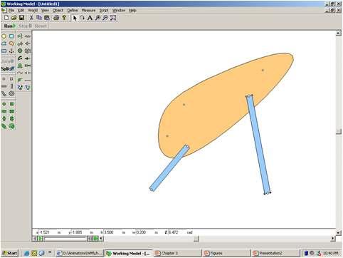
Mechanism Simulation With Working Model
 Mechanism Simulation With Working Model Shih-Liang Wang Department of Mechanical Engineering North Carolina A&T State University Greensboro, NC 27411 Introduction Kinematics is a study of motion and force
Synthesis of Planar Mechanisms, Part XI: Al-Jazari Quick Return-Motion Mechanism Galal Ali Hassaan Emeritus Professor, Mechanical Design & Production
 Synthesis of Planar Mechanisms, Part XI: Al-Jazari Quick Return-Motion Mechanism Galal Ali Hassaan Emeritus Professor, Mechanical Design & Production Department. Faculty of Engineering, Cairo University,
DETC APPROXIMATE MOTION SYNTHESIS OF SPHERICAL KINEMATIC CHAINS
 Proceedings of the ASME 2007 International Design Engineering Technical Conferences & Computers and Information in Engineering Conference IDETC/CIE 2007 September 4-7, 2007, Las Vegas, Nevada, USA DETC2007-34372
ME 321 Kinematics and Dynamics of Machines
 .0 INTRODUCTION ME Kinematics and Dynamics of Machines All Text References in these notes are for: Mechanism Design: Analysis and Synthesis, Volume, Fourth Edition, Erdman, Sandor and Kota, Prentice-Hall,
Optimization of Watt s Six-bar Linkage to Generate Straight and Parallel Leg Motion
 intehweb.com Optimization of Watt s Six-bar Linkage to Generate Straight and Parallel Leg Motion Hamid Mehdigholi and Saeed Akbarnejad Sharif University of Technology mehdi@sharif.ir Abstract: This paper
Computer-Aided Design of a Mechanism for the Continuous, Automated Assembly of Two Parts at High Speed: A Case Study
 W. L. Churchill E. Gilman C. Gow D. Yamartino R. L. Norton Dept. of Mechanical Engneering Worcester Polytechnic Institute Worcester, MA 01609 Computer-Aided Design of a Mechanism for the Continuous, Automated
Synthesis of Simple Planar Linkages
 MEAM 211 Synthesis of Simple Planar Linkages Professor Vijay Kumar Department of Mechanical Engineering and Applied Mechanics University of Pennsylvania January 15, 2006 1 Introduction Planar linkages
Simulation Model for Coupler Curve Generation using Five Bar Planar Mechanism With Rotation Constraint
 Simulation Model for Coupler Curve Generation using Five Bar Planar Mechanism With Rotation Constraint A. K. Abhyankar, S.Y.Gajjal Department of Mechanical Engineering, NBN Sinhgad School of Engineering,
ME 111: Engineering Drawing. Geometric Constructions
 ME 111: Engineering Drawing Lecture 2 01-08-2011 Geometric Constructions Indian Institute of Technology Guwahati Guwahati 781039 Geometric Construction Construction of primitive geometric forms (points,
PROGRAM LINKAGES. User Manual. By Robert L. Norton P.E. INTRODUCTION. Learning Tools
 INTRODUCTION PROGRAM LINKAGES User Manual By Robert L. Norton P.E. A Student Edition of Program Linkages is provided with the text Design of Machinery, 5ed. by Robert L. Norton. A student edition may only
Topics in geometry Exam 1 Solutions 7/8/4
 Topics in geometry Exam 1 Solutions 7/8/4 Question 1 Consider the following axioms for a geometry: There are exactly five points. There are exactly five lines. Each point lies on exactly three lines. Each
Synthesis of Planar Mechanisms, Part IX: Path Generation using 6 Bar 2 Sliders Mechanism
 International Journal of Computer Techniques - Volume 2 Issue 6, Nov- Dec 2015 RESEARCH ARTICLE Synthesis of Planar Mechanisms, Part IX: Path Generation using 6 Bar 2 Sliders Mechanism Galal Ali Hassaan
Chapter 1 Introduction
 Chapter 1 Introduction Generally all considerations in the force analysis of mechanisms, whether static or dynamic, the links are assumed to be rigid. The complexity of the mathematical analysis of mechanisms
Mechanism. Mechanism consists of linkages and joints.
 Mechanism Machines are mechanical devices used to accomplish work. A mechanism is a heart of a machine. It is the mechanical portion of the machine that has the function of transferring motion and forces
Kinematics of Machines Prof. A. K. Mallik Department of Mechanical Engineering Indian Institute of Technology, Kanpur. Module 10 Lecture 1
 Kinematics of Machines Prof. A. K. Mallik Department of Mechanical Engineering Indian Institute of Technology, Kanpur Module 10 Lecture 1 So far, in this course we have discussed planar linkages, which
The Study Of Five-Bar Mechanism With Variable Topology
 The Study Of Five-Bar Mechanism With Variable Topology Mulgundmath M. Prashant and Shrinivas S. Balli 1 Basaveshwar Engineering College Bagalkot: 587 102 (Karnatak) 1 Mechanical Engineering Department
September 23,
 1. In many ruler and compass constructions it is important to know that the perpendicular bisector of a secant to a circle is a diameter of that circle. In particular, as a limiting case, this obtains
2.007 Design and Manufacturing I Spring 2009
 MIT OpenCourseWare http://ocw.mit.edu 2.007 Design and Manufacturing I Spring 2009 For information about citing these materials or our Terms of Use, visit: http://ocw.mit.edu/terms. 2.007 Design and Manufacturing
Module 1 Topic C Lesson 14 Reflections
 Geometry Module 1 Topic C Lesson 14 Reflections The purpose of lesson 14 is for students to identify the properties of reflection, to use constructions to find line of reflection, get familiar with notations
2.1 Introduction. 2.2 Degree of Freedom DOF of a rigid body
 Chapter 2 Kinematics 2.1 Introduction 2.2 Degree of Freedom 2.2.1 DOF of a rigid body In order to control and guide the mechanisms to move as we desired, we need to set proper constraints. In order to
Analysis of a 4 Bar Crank-Rocker Mechanism Using COSMOSMotion
 Analysis of a 4 Bar Crank-Rocker Mechanism Using COSMOSMotion ME345: Modeling and Simulation Professor Frank Fisher Stevens Institute of Technology Last updated: June 29th, 2009 Table of Contents 1. Introduction
Definitions. Kinematics the study of constrained motion without regard to forces that cause that motion
 Notes_0_0 of efinitions Kinematics the stud of constrained motion without regard to forces that cause that motion namics the stud of how forces cause motion ausalit the relationship between cause and effect
Modelling of mechanical system CREATING OF KINEMATIC CHAINS
 Modelling of mechanical system CREATING OF KINEMATIC CHAINS Mechanism Definitions 1. a system or structure of moving parts that performs some function 2. is each system reciprocally joined moveable bodies
Session #5 2D Mechanisms: Mobility, Kinematic Analysis & Synthesis
 Session #5 2D Mechanisms: Mobility, Kinematic Analysis & Synthesis Courtesy of Design Simulation Technologies, Inc. Used with permission. Dan Frey Today s Agenda Collect assignment #2 Begin mechanisms
pine cone Ratio = 13:8 or 8:5
 Chapter 10: Introducing Geometry 10.1 Basic Ideas of Geometry Geometry is everywhere o Road signs o Carpentry o Architecture o Interior design o Advertising o Art o Science Understanding and appreciating
Mechanism Kinematics and Dynamics
 Mechanism Kinematics and Dynamics Final Project 1. The window shield wiper For the window wiper, (1). Select the length of all links such that the wiper tip X p (t) can cover a 120 cm window width. (2).
Using Classical Mechanism Concepts to Motivate Modern Mechanism Analysis and Synthesis Methods
 Using Classical Mechanism Concepts to Motivate Modern Mechanism Analysis and Synthesis Methods Robert LeMaster, Ph.D. 1 Abstract This paper describes a methodology by which fundamental concepts in the
Properties of a Circle Diagram Source:
 Properties of a Circle Diagram Source: http://www.ricksmath.com/circles.html Definitions: Circumference (c): The perimeter of a circle is called its circumference Diameter (d): Any straight line drawn
Geometry: Traditional Pathway
 GEOMETRY: CONGRUENCE G.CO Prove geometric theorems. Focus on validity of underlying reasoning while using variety of ways of writing proofs. G.CO.11 Prove theorems about parallelograms. Theorems include:
GEARED LINKAGE WITH LARGE ANGULAR STROKE USED IN TRACKED PV SYSTEMS
 Bulletin of the Transilvania University of Braşov Vol. 3 (5) - 010 Series I: Engineering Sciences GEARED LINKAGE WITH LARGE ANGULAR STROKE USED IN TRACKED PV SYSTEMS N.C. CREANGĂ 1 I. VIŞA 1 D.V. DIACONESCU
Kinematics Fundamentals CREATING OF KINEMATIC CHAINS
 Kinematics Fundamentals CREATING OF KINEMATIC CHAINS Mechanism Definitions 1. a system or structure of moving parts that performs some function 2. is each system reciprocally joined moveable bodies the
MATH 113 Section 8.2: Two-Dimensional Figures
 MATH 113 Section 8.2: Two-Dimensional Figures Prof. Jonathan Duncan Walla Walla University Winter Quarter, 2008 Outline 1 Classifying Two-Dimensional Shapes 2 Polygons Triangles Quadrilaterals 3 Other
Mid-point & Perpendicular Bisector of a line segment AB
 Mid-point & Perpendicular isector of a line segment Starting point: Line Segment Midpoint of 1. Open compasses so the points are approximately ¾ of the length of apart point 3. y eye - estimate the midpoint
Madison County Schools Suggested Geometry Pacing Guide,
 Madison County Schools Suggested Geometry Pacing Guide, 2016 2017 Domain Abbreviation Congruence G-CO Similarity, Right Triangles, and Trigonometry G-SRT Modeling with Geometry *G-MG Geometric Measurement
Kinematics of Machines. Brown Hills College of Engineering & Technology
 Introduction: mechanism and machines, kinematic links, kinematic pairs, kinematic chains, plane and space mechanism, kinematic inversion, equivalent linkages, four link planar mechanisms, mobility and
Unit 10 Circles 10-1 Properties of Circles Circle - the set of all points equidistant from the center of a circle. Chord - A line segment with
 Unit 10 Circles 10-1 Properties of Circles Circle - the set of all points equidistant from the center of a circle. Chord - A line segment with endpoints on the circle. Diameter - A chord which passes through
CONSTRUCTIONS Introduction Division of a Line Segment
 216 MATHEMATICS CONSTRUCTIONS 11 111 Introduction In Class IX, you have done certain constructions using a straight edge (ruler) and a compass, eg, bisecting an angle, drawing the perpendicular bisector
Articulated Robots! Robert Stengel! Robotics and Intelligent Systems! MAE 345, Princeton University, 2017
 Articulated Robots! Robert Stengel! Robotics and Intelligent Systems! MAE 345, Princeton University, 2017 Robot configurations Joints and links Joint-link-joint transformations! Denavit-Hartenberg representation
Pearson Mathematics Geometry Common Core 2015
 A Correlation of Pearson Mathematics Geometry Common Core 2015 to the Common Core State Standards for Bid Category 13-040-10 A Correlation of Pearson, Common Core Pearson Geometry Congruence G-CO Experiment
The hood (3) is linked to the body (1) through two rocker links (2 and 4).
 is linked to the body (1) through two rocker links (2 and 4).") DESIGN OF MACHINERY - th Ed SOLUTION MANUAL -- PROBLEM - Find three (or other number as assigned) of the following common devices. Sketch careful kinematic diagrams and find their total degrees of freedom.
DESIGN OF MACHINERY - th Ed SOLUTION MANUAL -- PROBLEM - Find three (or other number as assigned) of the following common devices. Sketch careful kinematic diagrams and find their total degrees of freedom.
Path Curvature of the Single Flier Eight-Bar Linkage
 Gordon R. Pennock ASME Fellow Associate Professor Edward C. Kinzel Research Assistant School of Mechanical Engineering, Purdue University, West Lafayette, Indiana 47907-2088 Path Curvature of the Single
ES302 Class Notes Trigonometric Applications in Geologic Problem Solving (updated Spring 2016)
") ES302 Class Notes Trigonometric Applications in Geologic Problem Solving (updated Spring 2016) I. Introduction a) Trigonometry study of angles and triangles i) Intersecting Lines (1) Points of intersection
ES302 Class Notes Trigonometric Applications in Geologic Problem Solving (updated Spring 2016) I. Introduction a) Trigonometry study of angles and triangles i) Intersecting Lines (1) Points of intersection
Curriki Geometry Glossary
 Curriki Geometry Glossary The following terms are used throughout the Curriki Geometry projects and represent the core vocabulary and concepts that students should know to meet Common Core State Standards.
Stable Grasp and Manipulation in 3D Space with 2-Soft-Fingered Robot Hand
 Stable Grasp and Manipulation in 3D Space with 2-Soft-Fingered Robot Hand Tsuneo Yoshikawa 1, Masanao Koeda 1, Haruki Fukuchi 1, and Atsushi Hirakawa 2 1 Ritsumeikan University, College of Information
Robotics (Kinematics) Winter 1393 Bonab University
 Winter 1393 Bonab University") Robotics () Winter 1393 Bonab University : most basic study of how mechanical systems behave Introduction Need to understand the mechanical behavior for: Design Control Both: Manipulators, Mobile Robots
Robotics () Winter 1393 Bonab University : most basic study of how mechanical systems behave Introduction Need to understand the mechanical behavior for: Design Control Both: Manipulators, Mobile Robots
Geometry. AIR Study Guide
 Geometry AIR Study Guide Table of Contents Topic Slide Formulas 3 5 Angles 6 Lines and Slope 7 Transformations 8 Constructions 9 10 Triangles 11 Congruency and Similarity 12 Right Triangles Only 13 Other
UNIT 5 GEOMETRY TEMPLATE CREATED BY REGION 1 ESA UNIT 5
 UNIT 5 GEOMETRY TEMPLATE CREATED BY REGION 1 ESA UNIT 5 Geometry Unit 5 Overview: Circles With and Without Coordinates In this unit, students prove basic theorems about circles, with particular attention
Dimensional Optimization for the Crank-Rocker Mechanism using TK Solver
 Int. J. Engng Ed. Vol. 13, No. 6, p. 417±425, 1997 0949-149X/91 $3.00+0.00 Printed in Great Britain. # 1997 TEMPUS Publications. Dimensional Optimization for the Crank-Rocker Mechanism using TK Solver
Study Guide - Geometry
 Study Guide - Geometry (NOTE: This does not include every topic on the outline. Take other steps to review those.) Page 1: Rigid Motions Page 3: Constructions Page 12: Angle relationships Page 14: Angle
Workspaces of planar parallel manipulators
 Workspaces of planar parallel manipulators Jean-Pierre Merlet Clément M. Gosselin Nicolas Mouly INRIA Sophia-Antipolis Dép. de Génie Mécanique INRIA Rhône-Alpes BP 93 Université Laval 46 Av. Felix Viallet
Slider-Cranks as Compatibility Linkages for Parametrizing Center-Point Curves
 David H. Myszka e-mail: dmyszka@udayton.edu Andrew P. Murray e-mail: murray@notes.udayton.edu University of Dayton, Dayton, OH 45469 Slider-Cranks as Compatibility Linkages for Parametrizing Center-Point
Problem 2.1. Complete the following proof of Euclid III.20, referring to the figure on page 1.
 Math 3181 Dr. Franz Rothe October 30, 2015 All3181\3181_fall15t2.tex 2 Solution of Test Name: Figure 1: Central and circumference angle of a circular arc, both obtained as differences Problem 2.1. Complete
Standards to Topics. Common Core State Standards 2010 Geometry
 Standards to Topics G-CO.01 Know precise definitions of angle, circle, perpendicular line, parallel line, and line segment, based on the undefined notions of point, line, distance along a line, and distance
Using Geometry to Design Simple Machines By Daniel D. Frey
 Using Geometry to Design Simple Machines By Daniel D. Frey Hi. I m Dan Fry. I m a teacher at MIT in Cambridge, Massachusetts, and today we re going to do a session about design of mechanisms. This should
Appendix. Correlation to the High School Geometry Standards of the Common Core State Standards for Mathematics
 Appendix Correlation to the High School Geometry Standards of the Common Core State Standards for Mathematics The correlation shows how the activities in Exploring Geometry with The Geometer s Sketchpad
Construction: Draw a ray with its endpoint on the left. Label this point B.
 Name: Ms. Ayinde Date: Geometry CC 1.13: Constructing Angles Objective: To copy angles and construct angle bisectors using a compass and straightedge. To construct an equilateral triangle. Copy an Angle:
Math 3315: Geometry Vocabulary Review Human Dictionary: WORD BANK
 Math 3315: Geometry Vocabulary Review Human Dictionary: WORD BANK [acute angle] [acute triangle] [adjacent interior angle] [alternate exterior angles] [alternate interior angles] [altitude] [angle] [angle_addition_postulate]
Taibah University Mechanical Engineering
 Instructor: Chapter 2 Kinematics Fundamentals 1. Introduction 2. Degrees of Freedom 3. Types of Motion 4. Links, Joints, and Kinematic Chains 5. Determining Degree of Freedom Degree of Freedom in Planar
Common Core Specifications for Geometry
 1 Common Core Specifications for Geometry Examples of how to read the red references: Congruence (G-Co) 2-03 indicates this spec is implemented in Unit 3, Lesson 2. IDT_C indicates that this spec is implemented
YEAR AT A GLANCE Student Learning Outcomes by Marking Period
 2014-2015 Term 1 Overarching/general themes: Tools to Build and Analyze Points, Lines and Angles Dates Textual References To Demonstrate Proficiency by the End of the Term Students Will : Marking Period
Synthesis of a Seven-Bar Slider Mechanism with Variable Topology for Motion between Two Dead-center Positions
 Synthesis of a Seven-Bar Slider Mechanism with Variable Topology for Motion between Two Dead-center Positions Umesh M.Daivagna, Member, IAENG, Shrinivas S.Balli Abstract The paper presents an analytical
Geometry Vocabulary Math Fundamentals Reference Sheet Page 1
 Math Fundamentals Reference Sheet Page 1 Acute Angle An angle whose measure is between 0 and 90 Acute Triangle A that has all acute Adjacent Alternate Interior Angle Two coplanar with a common vertex and
Geometry: Angle Relationships
 Geometry: Angle Relationships I. Define the following angles (in degrees) and draw an example of each. 1. Acute 3. Right 2. Obtuse 4. Straight Complementary angles: Supplementary angles: a + b = c + d
NFC ACADEMY COURSE OVERVIEW
 NFC ACADEMY COURSE OVERVIEW Geometry Honors is a full year, high school math course for the student who has successfully completed the prerequisite course, Algebra I. The course focuses on the skills and
MATH 31A HOMEWORK 9 (DUE 12/6) PARTS (A) AND (B) SECTION 5.4. f(x) = x + 1 x 2 + 9, F (7) = 0
 PARTS (A) AND (B) SECTION 5.4. f(x) = x + 1 x 2 + 9, F (7) = 0") FROM ROGAWSKI S CALCULUS (2ND ED.) SECTION 5.4 18.) Express the antiderivative F (x) of f(x) satisfying the given initial condition as an integral. f(x) = x + 1 x 2 + 9, F (7) = 28.) Find G (1), where
FROM ROGAWSKI S CALCULUS (2ND ED.) SECTION 5.4 18.) Express the antiderivative F (x) of f(x) satisfying the given initial condition as an integral. f(x) = x + 1 x 2 + 9, F (7) = 28.) Find G (1), where
Geometry Rules. Triangles:
 Triangles: Geometry Rules 1. Types of Triangles: By Sides: Scalene - no congruent sides Isosceles - 2 congruent sides Equilateral - 3 congruent sides By Angles: Acute - all acute angles Right - one right
TANGENTS. A link is the harmonious union point of curves with straight or curved corners. Links are the practical application of tangents.
 TANGENTS Two elements are tangent when they have a common point called the point of tangency. These elements are circles (or circumference arcs, in some cases also conic curves) and straight lines. A link
Geometry GEOMETRY. Congruence
 Geometry Geometry builds on Algebra I concepts and increases students knowledge of shapes and their properties through geometry-based applications, many of which are observable in aspects of everyday life.
Geometry - Chapter 1 - Corrective #1
 Class: Date: Geometry - Chapter 1 - Corrective #1 Short Answer 1. Sketch a figure that shows two coplanar lines that do not intersect, but one of the lines is the intersection of two planes. 2. Name two
Unit Activity Correlations to Common Core State Standards. Geometry. Table of Contents. Geometry 1 Statistics and Probability 8
 Unit Activity Correlations to Common Core State Standards Geometry Table of Contents Geometry 1 Statistics and Probability 8 Geometry Experiment with transformations in the plane 1. Know precise definitions
An Evaluation of Profiles for Disk Cams with In-line Roller Followers
 An Evaluation of Profiles for Disk Cams with In-line Roller Followers M.R.M.Rejab 1, M.M.Rahman 1, Z.Hamedon 2, M.S.M.Sani 1, M.M.Noor 1 and K.Kadirgama 1 1 Faculty of Mechanical Engineering, Universiti
Mathematics Standards for High School Geometry
 Mathematics Standards for High School Geometry Geometry is a course required for graduation and course is aligned with the College and Career Ready Standards for Mathematics in High School. Throughout
2. A straightedge can create straight line, but can't measure. A ruler can create straight lines and measure distances.
 5.1 Copies of Line Segments and Angles Answers 1. A drawing is a rough sketch and a construction is a process to create an exact and accurate geometric figure. 2. A straightedge can create straight line,