|
|
|
- Roy James
- 6 years ago
- Views:
Transcription
1
2
3
4
5
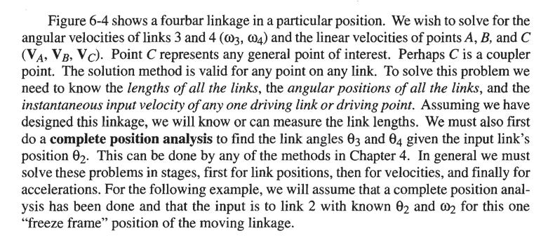
6 We will use point A as the reference point to find VB because A is in the same link as Band we have already solved for VA- Any vector equation can be solved for two unknowns. Each term has two parameters, namely magnitude and direction. There are then potentially six unknowns in this equation, two per term. We must know four of them to solve it. We know both magnitude and direction of VA and the direction of VB' We need to know one more parameter. S The term VBA represents the velocity of B with respect to A. If we assume that the link BA is rigid, then there can be no component of VBA which is directed along the line BA, because point B cannot move toward or away from point A without shrinking or stretching the rigid link! Therefore, the direction of VBA must be perpendicular to the line BA. Draw construction line qq through point B and perpendicular to BA to represent the direction of VBA, as shown in Figure 6-4a. 6 Now the vector equation can be solved graphically by drawing a vector diagram as shown in Figure 6-4b. Either drafting tools or a CAD package is necessary for this step. First draw velocity vector VA carefully to some scale, maintaining its direction. (It is drawn twice size in the figure.) The equation in step 4 says to add VBA to VA, so draw a line parallel to line qq across the tip of VA' The resultant, or left side of the equation, must close the vector diagram, from the tail of the first vector drawn (VA) to the tip of the last, so draw a line parallel to pp across the tail of VA' The intersection of these lines parallel to pp and qq defines the lengths of VB and VBA. The senses of the vectors are determined from reference to the equation. VA was added to VBA, so they must be arranged tip to tail. VB is the resultant, so it must be from the tail of the first to the tip of the last. The resultant vectors are shown in Figure 6-4b and d.
7
8 which the motion was pure rotation so that one of the terms in equation 6.5 (p. 243) would be zero. (We could as easily have looked for a point in pure translation to bootstrap the solution.) We then solved for the absolute velocity of that point (VA) using equations 6.5 and 6.7 (p. 244). (Steps I and 2) We then used the point (A) just solved for as a reference point to define the translation component in equation 6.5 written for a new point (B). Note that we needed to choose a second point (B) which was in the same rigid body as the reference point (A) which we had already solved and about which we could predict some aspect of the new point's (B's) velocity. In this example, we knew the direction of the velocity VB. In general this condition will be satisfied by any point on a link which is jointed to ground (as is link 4). In this example, we could not have solved for point C until we solved for B, because point C is on a floating link for which point we do not yet know the velocity direction. (Steps 3 and 4) To solve the equation for the second point (B), we also needed to recognize that the rotation component of velocity is directed perpendicular to the line connecting the two points in the link (B and A in the example). You will always know the direction of the rotation component in equation 6.5 if it represents a velocity difference (CASE 1) situation. If the rotation component relates two points in the same rigid body, then that velocity difference component is always perpendicular to the line connecting those two points (see Figure 6-2, p. 243). This will be true regardless of the two points selected. But, this is not true in a CASE 2 situation (see Figure 6-3, p. 244). (Steps 5 and 6) Once we found the absolute velocity (VB) of a second point on the same link (CASE 1) we could solve for the angular velocity of that link. (Note that points A and Bare both on link 3 and the velocity of point 04 is zero.) Once the angular velocities of all the links were known, we could solve for the linear velocity of any point (such as C) in any link using equation 6.5. To do so, we had to understand the concept of angular velocity as a free vector, meaning that it exists everywhere on the link at any given instant. It has no particular center. It has an infinity of potential centers. The link simply has an angular velocity, just as does a frisbee thrown and spun across the lawn. All points on afrisbee, if spinning while flying, obey equation 6.5. Left to its own devices, the frisbee will spin about its center of gravity (CG), which is close to the center of its circular shape. But if you are an expert frisbee player (and have rather pointed fingers), you can imagine catching that flying frisbee between your two index fingers in some off-center location (not at the CG), such that the frisbee continues to spin about your fingertips. In this somewhat far-fetched example of championship frisbee play, you will have taken the translation component of the frisbee's motion to zero, but its independent rotation component will still be present. Moreover, it will now be spinning about a different center (your fingers) than it was in flight (its CG). Thus this free vector of angular velocity «(0) is happy to attach itself to any point on the body. The body still has the same 00, regardless of the assumed center of rotation. It is this property that allows us to solve equation 6.5 for literally any point on a rigid body in complex motion referenced to any other point on that body. (Steps 7 and 8).

9 From equation 6.8b we can see that a fourbar linkage has 6 instant centers, a sixbar has 15, and an eightbar has 28. Figure 6-5 shows a fourbar linkage in an arbitrary position. It also shows a linear graph * which is useful for keeping track of which lcs have been found. This particular graph can be created by drawing a circle on which we mark off as many points as there are links in our assembly. We will then draw a line between the dots representing the link pairs each time we find an instant center. The resulting linear graph is the set of lines connecting the dots. It does not include the circle which was used only to place the dots. This graph is actually a geometric solution to equation 6.8b, since connecting all the points in pairs gives all the possible combinations of points taken two at a time. Some lcs can be found by inspection, using only the definition of the instant center. Note in Figure 6-5a that the four pin joints each satisfy the definition. They clearly must have the same velocity in both links at all times. These have been labeled h,2, h,3, h,4, and h,4' The order of the subscripts is immaterial. Instant center h,l is the same as h,2. These pin joint lcs are sometimes called "permanent" instant centers as they remain in the same location for all positions of the linkage. In general, instant centers will move to new locations as the linkage changes position, thus the adjective instant. In this fourbar example there are two more lcs to be found. It will help to use the Aronhold-Kennedy theorem,t also called Kennedy's rule, to locate them. Kennedy's rule: Any three bodies in plane motion will have exactly three instant centers, and they will lie on the same straight line. The first part of this rule is just a restatement of equation 6.8b for n = 3. It is the second clause in this rule that is most useful. Note that this rule does not require that the three bodies be connected in any way. We can use this rule, in conjunction with the linear graph, to find the remaining lcs which are not obvious from inspection. Figure 6.5b shows the construction necessary to find instant center 11,3. Figure 6-5c shows the construction necessary to find instant center h,4' The following example describes the procedure in detail.
10 The presence of slider joints makes finding the instant centers a little more subtle as is shown in the next example. Figure 6-6a shows a fourbar slider-crank linkage. Note that there are only three pin joints in this linkage. All pin joints are permanent instant centers. But the joint between links I and 4 is a rectilinear, sliding full joint. A sliding joint is kinematically equivalent to an infinitely long link, "pivoted" at infinity. Figure 6-6b shows a nearly equivalent pin-jointed version of the slider-crank in which link 4 is a very long rocker. Point B now swings through a shallow arc which is nearly a straight
11 line. It is clear in Figure 6-6b that, in this linkage, h,4 is at pivot 04. Now imagine increasing the length of this long, link 4 rocker even more. In the limit, link 4 approaches infinite length, the pivot 04 approaches infinity along the line which was originally the long rocker, and the arc motion of point B approaches a straight line. Thus, a slider joint will have its instant center at infinity along a line perpendicular to the direction of sliding as shown in Figure 6-6a.
12
13
14
15
16
17
18
19
20
21 See Figure 6-11 and compare equation 6.13e to equation 6.llf and its discussion under angular velocity ratio above. Equation 6.l3e shows that for any choice of rin and rout, the mechanical advantage responds to changes in angles v and /.l in opposite fashion to that of the angular velocity ratio. If the transmission angle /.l goes to zero (which we don't want it to do), the mechanical advantage also goes to zero regardless of the amount of input force or torque applied. But, when angle v goes to zero (which it can and does, twice per cycle in a Grashof linkage), the mechanical advantage becomes infinite! This is the principle of a rock-crusher mechanism as shown in Figure A quite moderate force applied to link 2 can generate a huge force on link 4 to crush the rock. Of course, we cannot expect to achieve the theoretical output of infinite force or torque magnitude, as the strengths of the links and joints will limit the maximum forces and torques obtainable. Another common example of a linkage which takes advantage of this theoretically infinite mechanical advantage at the toggle position is a ViseGrip locking pliers (see Figure P6-2l, p. 296). These two ratios, angular velocity ratio and mechanical advantage, provide useful, dimensionless indices of merit by which we can judge the relative quality of various linkage designs which may be proposed as solutions. Using Instant Centers in linkage Design In addition to providing a quick numerical velocity analysis, instant center analysis more importantly gives the designer a remarkable overview of the linkage's global behavior. It is quite difficult to mentally visualize the complex motion of a "floating" coupler link even in a simple fourbar linkage, unless you build a model or run a computer simulation. Because this complex coupler motion in fact reduces to an instantaneous pure rotation about the instant center h,3, finding that center allows the designer to visualize the motion of the coupler as a pure rotation. One can literally see the motion and the directions of velocities of any points of interest by relating them to the instant center. It is only necessary to draw the linkage in a few positions of interest, showing the instant center locations for each position.
.")
22 Figure 6-12 shows a practical example of how this visual, qualitative analysis technique could be applied to the design of an automobile rear suspension system. Most automobile suspension mechanisms are either fourbar linkages or fourbar slider-cranks, with the wheel assembly carried on the coupler (as was also shown in Figure 3-19, p. 108). Figure 6-l2a shows a rear suspension design from a domestic car of 1970's vintage which was later redesigned because of a disturbing tendency to "bump steer," i.e., turn the rear axle when hitting a bump on one side of the car. The figure is a view looking from the center of the car outward, showing the fourbar linkage which controls the up and down motion of one side of the rear axle and one wheel. Links 2 and 4 are pivoted to the frame of the car which is link 1. The wheel and axle assembly is rigidly attached to the coupler, link 3. Thus the wheel assembly has complex motion in the vertical plane. Ideally, one would like the wheel to move up and down in a straight vertical line when hitting a bump. Figure 6-12b shows the motion of the wheel and the new instant center (I1,3) location for the situation when one wheel has hit a bump. The velocity vector for the center of the wheel in each position is drawn perpendicular to its radius
23 from Ir,3. You can see that the wheel center has a significant horizontal component of motion as it moves up over the bump. This horizontal component causes the wheel center on that side of the car to move forward while it moves upward, thus turning the axle (about a vertical axis) and steering the car with the rear wheels in the same way that you steer a toy wagon. Viewing the path of the instant center over some range of motion gives a clear picture of the behavior of the coupler link. The undesirable behavior of this suspension linkage system could have been predicted from this simple instant center analysis before ever building the mechanism. Another practical example of the effective use of instant centers in linkage design is shown in Figure 6-13, which is an optical adjusting mechanism used to position a mirror and allow a small amount of rotational adjustment. [1] A more detailed account of this design case study [2] is provided in Chapter 18. The designer, K. Towfigh, recognized that Ir,3 at point E is an instantaneous "fixed pivot" and will allow very small pure rotations about that point with very small translational error. He then designed a one-piece, plastic fourbar linkage whose "pin joints" are thin webs of plastic which flex to allow slight rotation. This is termed a compliant linkage, one that uses elastic deformations of the links as hinges instead of pin joints. He then placed the mirror on the coupler at 11,3. Even the fixed link 1 is the same piece as the "movable links" and has a small set screw to provide the adjustment. A simple and elegant design. 6.5 CENTRODES Figure 6-14 illustrates the fact that the successive positions of an instant center (or centro) form a path of their own. This path, or locus, of the instant center is called the centrode. Since there are two links needed to create an instant center, there will be two centrodes associated with anyone instant center. These are formed by projecting the path of the instant center first on one link and then on the other. Figure 6-14a shows the locus of instant center Ir,3 as projected onto link 1. Because link I is stationary, or fixed, this is called the fixed centrode. By temporarily inverting the mechanism and fixing link 3
24
25 as the ground link, as shown in Figure 6-14b, we can move link 1 as the coupler and project the locus of 11,3 onto link 3. In the original linkage, link 3 was the moving coupler, so this is called the moving centrode. Figure 6-l4c shows the original linkage with both fixed and moving centrodes superposed. The definition of the instant center says that both links have the same velocity at that point, at that instant. Link 1 has zero velocity everywhere, as does the fixed centrode. So, as the linkage moves, the moving centrode must roll against the fixed centrode without slipping. If you cut the fixed and moving centrodes out of metal, as shown in Figure 6-14d, and roll the moving centrode (which is link 3) against the fixed centrode (which is link 1), the complex motion of link 3 will be identical to that of the original linkage. All of the coupler curves of points on link 3 will have the same path shapes as in the originallinkage. We now have, in effect, a "linkless" fourbar linkage, really one composed of two bodies which have these centrode shapes rolling against one another. Links 2 and 4 have been eliminated. Note that the example shown in Figure 6-14 is a non-grashof fourbar. The lengths of its centrodes are limited by the double-rocker toggle positions. All instant centers of a linkage will have centrodes. If the links are directly connected by a joint, such as lz,3, 13,4, h,2, and 11,4, their fixed and moving centrodes will degenerate to a point at that location on each link. The most interesting centrodes are those involving links not directly connected to one another such as 1 1,3 and h,4. If we look at the double-crank linkage in Figure 6-l5a in which links 2 and 4 both revolve fully, we see that the centrodes of 11,3 form closed curves. The motion of link 3 with respect to link 1 could be duplicated by causing these two centrodes to roll against one another without slipping. Note that there are two loops to the moving centrode. Both must roll on the single-loop fixed centrode to complete the motion of the equivalent double-crank linkage. We have so far dealt largely with the instant center 11,3. Instant center lz,4 involves two links which are each in pure rotation and not directly connected to one another. If we use a special-case Grashoflinkage with the links crossed (sometimes called an antiparallelogram linkage), the centrodes of lz,4 become ellipses as shown in Figure 6-l5b. To guarantee no slip, it will probably be necessary to put meshing teeth on each centrode. We then will have a pair of elliptical, noncircular gears, or gearset, which gives the same output motion as the original double-crank linkage and will have the same variations in the angular velocity ratio and mechanical advantage as the linkage had. Thus we can see that gearsets are also just fourbar linkages in disguise. Noncircular gears find much use in machinery, such as printing presses, where rollers must be speeded and slowed with some pattern during each cycle or revolution. More complicated shapes of noncircular gears are analogous to cams and followers in that the equivalent fourbar linkage must have variable-length links. Circular gears are just a special case of noncircular gears which give a constant angular velocity ratio and are widely used in all machines. Gears and gearsets will be dealt with in more detail in Chapter 10. In general, centrodes of crank-rockers and double- or triple-rockers will be open curves with asymptotes. Centrodes of double-crank linkages will be closed curves. Program FOURBARwill calculate and draw the fixed and moving centrodes for any linkage input to it. Input the datafiles F06-l4.4br, F06-15aAbr, and F06-l5bAbr into program FOURBARto see the centrodes of these linkage drawn as the linkages rotate.
26 A "linkless" linkage A common example of a mechanism made of centrodes is shown in Figure 6-16a. You have probably rocked in a Boston or Hitchcock rocking chair and experienced the soothing motions that it delivers to your body. You may have also rocked in a platfonn rocker as shown in Figure 6-16b and noticed that its motion did not feel as soothing. There are good kinematic reasons for the difference. The platform rocker has a fixed pin joint between the seat and the base (floor). Thus all parts of your body are in pure rotation along concentric arcs. You are in effect riding on the rocker of a linkage. The Boston rocker has a shaped (curved) base, or "runners," which rolls against the floor. These runners are usually not circular arcs. They have a higher-order curve contour. They are, in fact, moving centrodes. The floor is the fixed centrode. When one is rolled against the other, the chair and its occupant experience coupler curve motion. Every part of your body travels along a different sixth-order coupler curve which provides smooth accelerations and velocities and feels better than the cruder second-order (circular) motion of the platform rocker. Our ancestors, who carved these rocking chairs,
27 probably had never heard of fourbar linkages and centrodes, how to create comfortable motions. but they knew intuitively CUSpS Another example of a centrode which you probably use frequently is the path of the tire on your car or bicycle. As your tire rolls against the road without slipping, the road becomes a fixed centrode and the circumference of the tire is the moving centrode. The tire is, in effect, the coupler of a linkless fourbar linkage. All points on the contact surface of the tire move along cycloidal coupler curves and pass through a cusp of zero velocity when they reach the fixed centrode at the road surface as shown in Figure 6-17 a. All other points on the tire and wheel assembly travel along coupler curves which do not have cusps. This last fact is a clue to a means to identify coupler points which will have cusps in their coupler curve. If a coupler point is chosen to be on the moving centrode at one extreme of its path motion (i.e., at one of the positions ofh,3), then it will have a cusp in its coupler curve. Figure 6-17b shows a coupler curve of such a point, drawn with program FOURBAR. The right end of the coupler path touches the moving centrode and as a result has a cusp at that point. So, if you desire a cusp in your coupler motion, many are available. Simply choose a coupler point on the moving centrode of link 3. Read the diskfile F06-17bAbr into program FOURBARto animate that linkage with its coupler curve or centrodes. Note in Figure 6-14 (p. 264) that choosing any location of instant center Il,3 on the coupler as the coupler point will provide a cusp at that point. 6.6 VELOCITY OF SLIP When there is a sliding joint between two links and neither one is the ground link, the velocity analysis is more complicated. Figure 6-18 shows an inversion of the fourbar slider-crank mechanism in which the sliding joint is floating, i.e., not grounded. To solve for the velocity at the sliding joint A, we have to recognize that there is more than one point A at that joint. There is a point A as part of link 2 (Az), a point A as part oflink 3 (A3), and a point A as part of link 4 (A 4 ). This is a CASE 2 situation in which we have at least two points belonging to different links but occupying the same location at a given instant. Thus, the relative velocity equation 6.6 (p. 243) will apply. We can usually solve for the velocity of at least one of these points directly from the known input information using equation 6.7 (p. 244). It and equation 6.6 are all that are needed to solve for everything else. In this example link 2 is the driver, and 8z and OOz are given for the "freeze frame" position shown. We wish to solve for 004, the angular velocity of link 4, and also for the velocity of slip at the joint labeled A. In Figure 6-18 the axis of slip is shown to be tangent to the slider motion and is the line along which all sliding occurs between links 3 and 4. The axis of transmission is defined to be perpendicular to the axis of slip and pass through the slider joint at A. This axis of transmission is the only line along which we can transmit motion or force across the slider joint, except for friction. We will assume friction to be negligible in this example. Any force or velocity vector applied to point A can be resolved into two components along these two axes which provide a translating and rotating, local coordinate system for analysis at the joint. The component along the axis of transmission will do useful work at the joint. But, the component along the axis of slip does no work, except friction work.
28
29
30
31
32
33
34
35
36
37
38
39
40
41
42
43
MENG 372 Chapter 3 Graphical Linkage Synthesis. All figures taken from Design of Machinery, 3 rd ed. Robert Norton 2003
 MENG 372 Chapter 3 Graphical Linkage Synthesis All figures taken from Design of Machinery, 3 rd ed. Robert Norton 2003 1 Introduction Synthesis: to design or create a mechanism to give a certain motion
Theory of Machines Course # 1
 Theory of Machines Course # 1 Ayman Nada Assistant Professor Jazan University, KSA. arobust@tedata.net.eg March 29, 2010 ii Sucess is not coming in a day 1 2 Chapter 1 INTRODUCTION 1.1 Introduction Mechanisms
Mechanism Design. Four-bar coupler-point curves
 Mechanism Design Four-bar coupler-point curves Four-bar coupler-point curves A coupler is the most interesting link in any linkage. It is in complex motion, and thus points on the coupler can have path
Kinematics of Machines Prof. A. K. Mallik Department of Mechanical Engineering Indian Institute of Technology, Kanpur. Module - 3 Lecture - 1
 Kinematics of Machines Prof. A. K. Mallik Department of Mechanical Engineering Indian Institute of Technology, Kanpur Module - 3 Lecture - 1 In an earlier lecture, we have already mentioned that there
Mechanisms. Updated: 18Apr16 v7
 Mechanisms Updated: 8Apr6 v7 Mechanism Converts input motion or force into a desired output with four combinations of input and output motion Rotational to Oscillating Rotational to Rotational Rotational
NOT COMPLETE. θ 4 B 2 = O 2 O 4 = A 2 = A 1 B 1 O 2 KINEMATIC SYNTHESIS
 ME 35 NOT COMPLETE Design Design a crank-rocker four-bar (Grashof) where the input link rotates completely and the output link (the follower) rocks back and forth with a prescribed angle The design requires
SAMPLE STUDY MATERIAL. Mechanical Engineering. Postal Correspondence Course. Theory of Machines. GATE, IES & PSUs
 TOM - ME GATE, IES, PSU 1 SAMPLE STUDY MATERIAL Mechanical Engineering ME Postal Correspondence Course Theory of Machines GATE, IES & PSUs TOM - ME GATE, IES, PSU 2 C O N T E N T TOPIC 1. MACHANISMS AND
Kinematics of Machines Prof. A. K. Mallik Department of Mechanical Engineering Indian Institute of Technology, Kanpur. Module 10 Lecture 1
 Kinematics of Machines Prof. A. K. Mallik Department of Mechanical Engineering Indian Institute of Technology, Kanpur Module 10 Lecture 1 So far, in this course we have discussed planar linkages, which
Solutions to Chapter 6 Exercise Problems A 1 O 4 B 2
 Solutions to Chapter 6 Exercise Problems Problem 6.1: Design a double rocker, four-bar linkage so that the base link is 2-in and the output rocker is 1-in long. The input link turns counterclockwise 60
Position Analysis
 Position Analysis 2015-03-02 Position REVISION The position of a point in the plane can be defined by the use of a position vector Cartesian coordinates Polar coordinates Each form is directly convertible
MACHINES AND MECHANISMS
 MACHINES AND MECHANISMS APPLIED KINEMATIC ANALYSIS Fourth Edition David H. Myszka University of Dayton PEARSON ж rentice Hall Pearson Education International Boston Columbus Indianapolis New York San Francisco
WEEKS 1-2 MECHANISMS
 References WEEKS 1-2 MECHANISMS (METU, Department of Mechanical Engineering) Text Book: Mechanisms Web Page: http://www.me.metu.edu.tr/people/eres/me301/in dex.ht Analitik Çözümlü Örneklerle Mekanizma
Kinematics: Intro. Kinematics is study of motion
 Kinematics is study of motion Kinematics: Intro Concerned with mechanisms and how they transfer and transform motion Mechanisms can be machines, skeletons, etc. Important for CG since need to animate complex
2.1 Introduction. 2.2 Degree of Freedom DOF of a rigid body
 Chapter 2 Kinematics 2.1 Introduction 2.2 Degree of Freedom 2.2.1 DOF of a rigid body In order to control and guide the mechanisms to move as we desired, we need to set proper constraints. In order to
Chapter 4. Mechanism Design and Analysis
 Chapter 4. Mechanism Design and Analysis All mechanical devices containing moving parts are composed of some type of mechanism. A mechanism is a group of links interacting with each other through joints
Position and Displacement Analysis
 Position and Displacement Analysis Introduction: In this chapter we introduce the tools to identifying the position of the different points and links in a given mechanism. Recall that for linkages with
10/11/07 1. Motion Control (wheeled robots) Representing Robot Position ( ) ( ) [ ] T
![10/11/07 1. Motion Control (wheeled robots) Representing Robot Position ( ) ( ) [ ] T](/thumbs/79/79288754.jpg "10/11/07 1. Motion Control (wheeled robots) Representing Robot Position ( ) ( ) [ ] T") 3 3 Motion Control (wheeled robots) Introduction: Mobile Robot Kinematics Requirements for Motion Control Kinematic / dynamic model of the robot Model of the interaction between the wheel and the ground
3 3 Motion Control (wheeled robots) Introduction: Mobile Robot Kinematics Requirements for Motion Control Kinematic / dynamic model of the robot Model of the interaction between the wheel and the ground
September 20, Chapter 5. Simple Mechanisms. Mohammad Suliman Abuhaiba, Ph.D., PE
 Chapter 5 Simple Mechanisms 1 Mohammad Suliman Abuhaiba, Ph.D., PE 2 Assignment #1 All questions at the end of chapter 1 st Exam: Saturday 29/9/2018 3 Kinematic Link or Element kinematic link (link) or
Motion Control (wheeled robots)
") Motion Control (wheeled robots) Requirements for Motion Control Kinematic / dynamic model of the robot Model of the interaction between the wheel and the ground Definition of required motion -> speed control,
Motion Control (wheeled robots) Requirements for Motion Control Kinematic / dynamic model of the robot Model of the interaction between the wheel and the ground Definition of required motion -> speed control,
Chapter 1 Introduction
 Chapter 1 Introduction Generally all considerations in the force analysis of mechanisms, whether static or dynamic, the links are assumed to be rigid. The complexity of the mathematical analysis of mechanisms
Lecture 3. Planar Kinematics
 Matthew T. Mason Mechanics of Manipulation Outline Where are we? s 1. Foundations and general concepts. 2.. 3. Spherical and spatial kinematics. Readings etc. The text: By now you should have read Chapter
Mobile Robot Kinematics
 Mobile Robot Kinematics Dr. Kurtuluş Erinç Akdoğan kurtuluserinc@cankaya.edu.tr INTRODUCTION Kinematics is the most basic study of how mechanical systems behave required to design to control Manipulator
Kinematics of Machines. Brown Hills College of Engineering & Technology
 Introduction: mechanism and machines, kinematic links, kinematic pairs, kinematic chains, plane and space mechanism, kinematic inversion, equivalent linkages, four link planar mechanisms, mobility and
Modelling of mechanical system CREATING OF KINEMATIC CHAINS
 Modelling of mechanical system CREATING OF KINEMATIC CHAINS Mechanism Definitions 1. a system or structure of moving parts that performs some function 2. is each system reciprocally joined moveable bodies
Curriki Geometry Glossary
 Curriki Geometry Glossary The following terms are used throughout the Curriki Geometry projects and represent the core vocabulary and concepts that students should know to meet Common Core State Standards.
Homework 4 PROBLEMS ON THREE POSITION GUIDANCE
 Homework 4 ROLEMS ON THREE OSITION GUIDNE. In the synthesis of three positions of a plane by a four-bar mechanism, in the graphical method and were selected arbitrarily and, were determined as the corresponding
Lesson 1: Introduction to Pro/MECHANICA Motion
 Lesson 1: Introduction to Pro/MECHANICA Motion 1.1 Overview of the Lesson The purpose of this lesson is to provide you with a brief overview of Pro/MECHANICA Motion, also called Motion in this book. Motion
CHAPTER 1 : KINEMATICS
 KINEMATICS : It relates to the study of the relative motion between the parts of a machine. Let us consider a reciprocating engine, in this the piston is made to reciprocate in the cylinderdue to the applied
PROBLEMS AND EXERCISES PROBLEMS
 64 Fundamentals of Kinematics and Dynamics of Machines and Mechanisms PROBLEMS AND EXERCISES PROBLEMS 1. In Figure 1.14c an inverted slider-crank mechanism is shown. b. If the input is the displacement
Structural Configurations of Manipulators
 Structural Configurations of Manipulators 1 In this homework, I have given information about the basic structural configurations of the manipulators with the concerned illustrations. 1) The Manipulator
Chapter 4: Kinematics of Rigid Bodies
 Chapter 4: Kinematics of Rigid Bodies Advanced Dynamics Lecturer: Hossein Nejat Fall 2016 A rigid body is defined to be a collection of particles whose distance of separation is invariant. In this circumstance,
ROSE-HULMAN INSTITUTE OF TECHNOLOGY
 Introduction to Working Model Welcome to Working Model! What is Working Model? It's an advanced 2-dimensional motion simulation package with sophisticated editing capabilities. It allows you to build and
Goals: - to be able to recognize the position-time, velocity-time and acceleration-time graphs of each of these main types of motion:
 Unit: One-Dimensional Kinematics Level: 1 Prerequisites: None Points to: Goals: - to be able to recognize the position-time, velocity-time and acceleration-time graphs of each of these main types of motion:
CMPUT 412 Motion Control Wheeled robots. Csaba Szepesvári University of Alberta
 CMPUT 412 Motion Control Wheeled robots Csaba Szepesvári University of Alberta 1 Motion Control (wheeled robots) Requirements Kinematic/dynamic model of the robot Model of the interaction between the wheel
Overview. What is mechanism? What will I learn today? ME 311: Dynamics of Machines and Mechanisms Lecture 2: Synthesis
 Overview ME 311: Dynamics of Machines and Mechanisms Lecture 2: Synthesis By Suril Shah Some fundamentals Synthesis Function, path and motion generation Limiting condition Dimensional synthesis 1 2 What
Introduction to Solid Modeling Using SolidWorks 2008 COSMOSMotion Tutorial Page 1
 Introduction to Solid Modeling Using SolidWorks 2008 COSMOSMotion Tutorial Page 1 In this tutorial, we will learn the basics of performing motion analysis using COSMOSMotion. Although the tutorial can
Kinematics of Machines Prof. A. K. Mallik Department of Mechanical Engineering Indian Institute of Technology, Kanpur. Module - 2 Lecture - 1
 Kinematics of Machines Prof. A. K. Mallik Department of Mechanical Engineering Indian Institute of Technology, Kanpur Module - 2 Lecture - 1 The topic of today s lecture is mobility analysis. By mobility
Manipulator Dynamics: Two Degrees-of-freedom
 Manipulator Dynamics: Two Degrees-of-freedom 2018 Max Donath Manipulator Dynamics Objective: Calculate the torques necessary to overcome dynamic effects Consider 2 dimensional example Based on Lagrangian
Session #5 2D Mechanisms: Mobility, Kinematic Analysis & Synthesis
 Session #5 2D Mechanisms: Mobility, Kinematic Analysis & Synthesis Courtesy of Design Simulation Technologies, Inc. Used with permission. Dan Frey Today s Agenda Collect assignment #2 Begin mechanisms
2.007 Design and Manufacturing I Spring 2009
 MIT OpenCourseWare http://ocw.mit.edu 2.007 Design and Manufacturing I Spring 2009 For information about citing these materials or our Terms of Use, visit: http://ocw.mit.edu/terms. 2.007 Design and Manufacturing
SYNTHESIS OF PLANAR MECHANISMS FOR PICK AND PLACE TASKS WITH GUIDING LOCATIONS
 Proceedings of the ASME 2013 International Design Engineering Technical Conferences and Computers and Information in Engineering Conference IDETC/CIE 2013 August 4-7, 2013, Portland, Oregon, USA DETC2013-12021
Robotics (Kinematics) Winter 1393 Bonab University
 Winter 1393 Bonab University") Robotics () Winter 1393 Bonab University : most basic study of how mechanical systems behave Introduction Need to understand the mechanical behavior for: Design Control Both: Manipulators, Mobile Robots
Robotics () Winter 1393 Bonab University : most basic study of how mechanical systems behave Introduction Need to understand the mechanical behavior for: Design Control Both: Manipulators, Mobile Robots
Cam makes a higher kinematic pair with follower. Cam mechanisms are widely used because with them, different types of motion can be possible.
 CAM MECHANISMS Cam makes a higher kinematic pair with follower. Cam mechanisms are widely used because with them, different types of motion can be possible. Cams can provide unusual and irregular motions
Physics 101, Lab 1: LINEAR KINEMATICS PREDICTION SHEET
 Physics 101, Lab 1: LINEAR KINEMATICS PREDICTION SHEET After reading through the Introduction, Purpose and Principles sections of the lab manual (and skimming through the procedures), answer the following
ME 321 Kinematics and Dynamics of Machines
 .0 INTRODUCTION ME Kinematics and Dynamics of Machines All Text References in these notes are for: Mechanism Design: Analysis and Synthesis, Volume, Fourth Edition, Erdman, Sandor and Kota, Prentice-Hall,
Chapter 5. Transforming Shapes
 Chapter 5 Transforming Shapes It is difficult to walk through daily life without being able to see geometric transformations in your surroundings. Notice how the leaves of plants, for example, are almost
CHAPTER 3 MATHEMATICAL MODEL
 38 CHAPTER 3 MATHEMATICAL MODEL 3.1 KINEMATIC MODEL 3.1.1 Introduction The kinematic model of a mobile robot, represented by a set of equations, allows estimation of the robot s evolution on its trajectory,
Chapter 12 Notes: Optics
 Chapter 12 Notes: Optics How can the paths traveled by light rays be rearranged in order to form images? In this chapter we will consider just one form of electromagnetic wave: visible light. We will be
Model Library Mechanics
 Model Library Mechanics Using the libraries Mechanics 1D (Linear), Mechanics 1D (Rotary), Modal System incl. ANSYS interface, and MBS Mechanics (3D) incl. CAD import via STL and the additional options
SolidWorks Assembly Files. Assemblies Mobility. The Mating Game Mating features. Mechanical Mates Relative rotation about axes
 Assemblies Mobility SolidWorks Assembly Files An assembly file is a collection of parts The first part brought into an assembly file is fixed Other parts are constrained relative to that part (or other
MECHANICAL ENGINEERING
 MECHANICAL ENGINEERING ESE TOPICWISE OBJECTIVE SOLVED PAPER-II FROM (1995-2018) UPSC Engineering Services Examination State Engineering Service Examination & Public Sector Examination. IES MASTER PUBLICATION
KINEMATICS OF MACHINES. Dr.V.SUNDARESWARAN PROFESSOR OF MECHANICAL ENGG. COLLEGE OF ENGINEERING, GUINDY ANNA UNIVERSITY CHENNAI
 KINEMATICS OF MACHINES Dr.V.SUNDARESWARAN PROFESSOR OF MECHANICAL ENGG. COLLEGE OF ENGINEERING, GUINDY ANNA UNIVERSITY CHENNAI 600 025 MECHANICS Science dealing with motion DIVISIONS OF MECHANICS Statics
The hood (3) is linked to the body (1) through two rocker links (2 and 4).
 is linked to the body (1) through two rocker links (2 and 4).") DESIGN OF MACHINERY - th Ed SOLUTION MANUAL -- PROBLEM - Find three (or other number as assigned) of the following common devices. Sketch careful kinematic diagrams and find their total degrees of freedom.
DESIGN OF MACHINERY - th Ed SOLUTION MANUAL -- PROBLEM - Find three (or other number as assigned) of the following common devices. Sketch careful kinematic diagrams and find their total degrees of freedom.
Name: Date: Concave Mirrors. 1. Reflect the rays off of the concave mirror. Principal axis
 Name: Date: Concave Mirrors 1. Reflect the rays off of the concave mirror. Principal axis Concave Mirrors Draw one line on each diagram to illustrate each of the following rules: a. Any ray that travels
Modeling a Gear Standard Tools, Surface Tools Solid Tool View, Trackball, Show-Hide Snaps Window 1-1
 Modeling a Gear This tutorial describes how to create a toothed gear. It combines using wireframe, solid, and surface modeling together to create a part. The model was created in standard units. To begin,
Lesson 5: Definition of Rotation and Basic Properties
 Student Outcomes Students know how to rotate a figure a given degree around a given center. Students know that rotations move lines to lines, rays to rays, segments to segments, and angles to angles. Students
Mechanism. Mechanism consists of linkages and joints.
 Mechanism Machines are mechanical devices used to accomplish work. A mechanism is a heart of a machine. It is the mechanical portion of the machine that has the function of transferring motion and forces
ROSE-HULMAN INSTITUTE OF TECHNOLOGY
 More Working Model Today we are going to look at even more features of Working Model. Specifically, we are going to 1) Learn how to add ropes and rods. 2) Learn how to connect object using joints and slots.
Kinematics Fundamentals CREATING OF KINEMATIC CHAINS
 Kinematics Fundamentals CREATING OF KINEMATIC CHAINS Mechanism Definitions 1. a system or structure of moving parts that performs some function 2. is each system reciprocally joined moveable bodies the
A rigid body free to move in a reference frame will, in the general case, have complex motion, which is simultaneously a combination of rotation and
 050389 - Analtical Elements of Mechanisms Introduction. Degrees of Freedom he number of degrees of freedom (DOF) of a sstem is equal to the number of independent parameters (measurements) that are needed
Mechanism Synthesis. Introduction: Design of a slider-crank mechanism
 Mechanism Synthesis Introduction: Mechanism synthesis is the procedure by which upon identification of the desired motion a specific mechanism (synthesis type), and appropriate dimensions of the linkages
Kinematics, Dynamics, and Design of Machinery, 3 nd Ed.
 MATLAB KINEMATIC PROGRAMS To Supplement the Textbook Kinematics, Dynamics, and Design of Machinery, 3 nd Ed. By K. J. Waldron, G. L. Kinzel, and S. Agrawal 2016 by G. Kinzel Department of Mechanical and
Unit 1, Lesson 1: Moving in the Plane
 Unit 1, Lesson 1: Moving in the Plane Let s describe ways figures can move in the plane. 1.1: Which One Doesn t Belong: Diagrams Which one doesn t belong? 1.2: Triangle Square Dance m.openup.org/1/8-1-1-2
Getting started with Solid Edge with Synchronous Technology
 Getting started with Solid Edge with Synchronous Technology Publication Number MU29000-ENG-1000 Proprietary and Restricted Rights Notice This software and related documentation are proprietary to Siemens
Graphics and Interaction Transformation geometry and homogeneous coordinates
 433-324 Graphics and Interaction Transformation geometry and homogeneous coordinates Department of Computer Science and Software Engineering The Lecture outline Introduction Vectors and matrices Translation
Analysis of a 4 Bar Crank-Rocker Mechanism Using COSMOSMotion
 Analysis of a 4 Bar Crank-Rocker Mechanism Using COSMOSMotion ME345: Modeling and Simulation Professor Frank Fisher Stevens Institute of Technology Last updated: June 29th, 2009 Table of Contents 1. Introduction
COMP30019 Graphics and Interaction Transformation geometry and homogeneous coordinates
 COMP30019 Graphics and Interaction Transformation geometry and homogeneous coordinates Department of Computer Science and Software Engineering The Lecture outline Introduction Vectors and matrices Translation
3.2 A Three-Bar Linkage 51
 3.2 A Three-Bar Linkage 51 It may happen that the drawing in Euclidean view is too big or too small. You can use the zooming tools to change this. There is a Zoom-In and a Zoom-Out tool below the Euclidean
Math Section 4.2 Radians, Arc Length, and Area of a Sector
 Math 1330 - Section 4.2 Radians, Arc Length, and Area of a Sector The word trigonometry comes from two Greek roots, trigonon, meaning having three sides, and meter, meaning measure. We have already defined
Structure from Motion. Prof. Marco Marcon
 Structure from Motion Prof. Marco Marcon Summing-up 2 Stereo is the most powerful clue for determining the structure of a scene Another important clue is the relative motion between the scene and (mono)
Analytical synthesis of aeroplane landing gear by using compactness algorithm
 National Journal of Multidisciplinary Research and Development ISSN: 2455-9040 Impact Factor: RJIF 5.22 www.nationaljournals.com Volume 3; Issue 1; January 2018; Page No. 486-490 Analytical synthesis of
CO2 Rail Car. Wheel Rear Px. on the Command Manager toolbar.
 Chapter 6 CO2 Rail Car Wheel Rear Px A. Sketch Construction Lines. Step 1. Click File Menu > New, click Part Metric and OK. Step 2. Click Front (plane) in the Feature Manager (left panel), Fig. 1. Step
One Dimensional Motion (Part I and Part II)
") One Dimensional Motion (Part I and Part II) Purpose:To understand the relationship between displacement (position), motion (velocity), and change in motion (acceleration). Topics of PART I and PART II:
One Dimensional Motion (Part I and Part II) Purpose:To understand the relationship between displacement (position), motion (velocity), and change in motion (acceleration). Topics of PART I and PART II:
LIBRARY UNIVERSITY OF ILLINOIS7'^esAnGsyauu- m 2 m
 m 2 m LIBRARY UNIVERSITY OF ILLINOIS7'^esAnGsyauu- URBANA ^ ^ UNIVERSITY OF ILLINOIS BULLETIN Vol. XVIII Issued Weekly NOVEMBER 22, 1920 No, 12 Entered as second-class matter December 11, 1912, at the
NONCIRCULAR GEAR DESIGN AND GENERATION BY RACK CUTTER
 , TECHNOLOGIES IN MACHINE BUILDING, ISSN 1221-4566, 2011 NONCIRCULAR GEAR DESIGN AND GENERATION BY RACK CUTTER Marius Vasie,LaurenŃia Andrei University Dunărea de Jos of GalaŃi, Romania v_marius_gl@yahoo.com
Math 1330 Section 4.2 Section 4.2: Radians, Arc Length, and Area of a Sector
 Section 4.: Radians, Arc Length, and Area of a Sector An angle is formed by two rays that have a common endpoint (vertex). One ray is the initial side and the other is the terminal side. We typically will
Projectile Motion SECTION 3. Two-Dimensional Motion. Objectives. Use of components avoids vector multiplication.
 Projectile Motion Key Term projectile motion Two-Dimensional Motion Previously, we showed how quantities such as displacement and velocity were vectors that could be resolved into components. In this section,
SMMG October 14 th, 2006 featuring Dr. Michael Starbird Circles, Rings, and Tractors: Clever Cleaving for Finding Formulas
 SMMG October 14 th, 2006 featuring Dr. Michael Starbird Circles, Rings, and Tractors: Clever Cleaving for Finding Formulas 1. The Polygon Sweep a) On one of the colored pieces of construction paper you
Direction Fields; Euler s Method
 Direction Fields; Euler s Method It frequently happens that we cannot solve first order systems dy (, ) dx = f xy or corresponding initial value problems in terms of formulas. Remarkably, however, this
Analytical and Applied Kinematics
 Analytical and Applied Kinematics Vito Moreno moreno@engr.uconn.edu 860-614-2365 (cell) http://www.engr.uconn.edu/~moreno Office EB1, hours Thursdays 10:00 to 5:00 1 This course introduces a unified and
Science 8 Chapter 5 Section 1
 Science 8 Chapter 5 Section 1 The Ray Model of Light (pp. 172-187) Models of Light wave model of light: a model in which light is a type of wave that travels through space and transfers energy from one
Conic Sections and Analytic Geometry
 Chapter 9 Conic Sections and Analytic Geometry Chapter 9 Conic Sections and Analytic Geometry 9.1 The Ellipse 9.2 The Hyperbola 9.3 The Parabola 9.4 Rotation of Axes 9.5 Parametric Equations 9.6 Conic
Stress Analysis of Cross Groove Type Constant Velocity Joint
 TECHNICAL REPORT Stress Analysis of Cross Groove Type Constant Velocity Joint H. SAITO T. MAEDA The driveshaft is the part that transmits the vehicle's engine torque and rotation to the tires, and predicting
GEO-SLOPE International Ltd , 700-6th Ave SW, Calgary, AB, Canada T2P 0T8 Main: Fax:
 Grid and Radius GEO-SLOPE International Ltd. www.geo-slope.com 1200, 700-6th Ave SW, Calgary, AB, Canada T2P 0T8 Main: +1 403 269 2002 Fax: +1 888 463 2239 Introduction In early limit equilibrium slope
A Comprehensive Introduction to SolidWorks 2011
 A Comprehensive Introduction to SolidWorks 2011 Godfrey Onwubolu, Ph.D. SDC PUBLICATIONS www.sdcpublications.com Schroff Development Corporation Chapter 2 Geometric Construction Tools Objectives: When
ME 115(b): Final Exam, Spring
: Final Exam, Spring") ME 115(b): Final Exam, Spring 2005-06 Instructions 1. Limit your total time to 5 hours. That is, it is okay to take a break in the middle of the exam if you need to ask me a question, or go to dinner,
ME 115(b): Final Exam, Spring 2005-06 Instructions 1. Limit your total time to 5 hours. That is, it is okay to take a break in the middle of the exam if you need to ask me a question, or go to dinner,
Engineering Physics 1 Dr. M. K. Srivastava Department of Physics Indian Institute of Technology- Roorkee. Module-01 Lecture 03 Double Refraction
 Engineering Physics 1 Dr. M. K. Srivastava Department of Physics Indian Institute of Technology- Roorkee Module-01 Lecture 03 Double Refraction Okay, this is the third lecture of the five lecture series
ME 115(b): Final Exam, Spring
: Final Exam, Spring") ME 115(b): Final Exam, Spring 2011-12 Instructions 1. Limit your total time to 5 hours. That is, it is okay to take a break in the middle of the exam if you need to ask me a question, or go to dinner,
ME 115(b): Final Exam, Spring 2011-12 Instructions 1. Limit your total time to 5 hours. That is, it is okay to take a break in the middle of the exam if you need to ask me a question, or go to dinner,
Week 5: Assignment: Animation
 Animating a Tennis Ball This tutorial will teach you the main principles of animation, specifically how to animate a tennis ball being fired from a cannon and bouncing off a wall to a stop. We would recommend
Substituting a 2 b 2 for c 2 and using a little algebra, we can then derive the standard equation for an ellipse centred at the origin,
 Conics onic sections are the curves which result from the intersection of a plane with a cone. These curves were studied and revered by the ancient Greeks, and were written about extensively by both Euclid
IMECE FUNCTIONAL INTERFACE-BASED ASSEMBLY MODELING
 Proceedings of IMECE2005 2005 ASME International Mechanical Engineering Congress and Exposition November 5-11, 2005, Orlando, Florida USA IMECE2005-79945 FUNCTIONAL INTERFACE-BASED ASSEMBLY MODELING James
A simple example. Assume we want to find the change in the rotation angles to get the end effector to G. Effect of changing s
 CENG 732 Computer Animation This week Inverse Kinematics (continued) Rigid Body Simulation Bodies in free fall Bodies in contact Spring 2006-2007 Week 5 Inverse Kinematics Physically Based Rigid Body Simulation
Unit 2: Locomotion Kinematics of Wheeled Robots: Part 3
 Unit 2: Locomotion Kinematics of Wheeled Robots: Part 3 Computer Science 4766/6778 Department of Computer Science Memorial University of Newfoundland January 28, 2014 COMP 4766/6778 (MUN) Kinematics of
SPECIAL TECHNIQUES-II
 SPECIAL TECHNIQUES-II Lecture 19: Electromagnetic Theory Professor D. K. Ghosh, Physics Department, I.I.T., Bombay Method of Images for a spherical conductor Example :A dipole near aconducting sphere The
CCGPS UNIT 5 Semester 2 COORDINATE ALGEBRA Page 1 of 38. Transformations in the Coordinate Plane
 CCGPS UNIT 5 Semester 2 COORDINATE ALGEBRA Page 1 of 38 Transformations in the Coordinate Plane Name: Date: MCC9-12.G.CO.1 Know precise definitions of angle, circle, perpendicular line, parallel line,
[3] Rigid Body Analysis
![[3] Rigid Body Analysis](/thumbs/92/109073357.jpg "[3] Rigid Body Analysis") [3] Rigid Body Analysis Page 1 of 53 [3] Rigid Body Analysis [3.1] Equilibrium of a Rigid Body [3.2] Equations of Equilibrium [3.3] Equilibrium in 3-D [3.4] Simple Trusses [3.5] The Method of Joints [3.6]
[3] Rigid Body Analysis Page 1 of 53 [3] Rigid Body Analysis [3.1] Equilibrium of a Rigid Body [3.2] Equations of Equilibrium [3.3] Equilibrium in 3-D [3.4] Simple Trusses [3.5] The Method of Joints [3.6]
7 Modelling and Animating Human Figures. Chapter 7. Modelling and Animating Human Figures. Department of Computer Science and Engineering 7-1
 Modelling and Animating Human Figures 7-1 Introduction Modeling and animating an articulated figure is one of the most formidable tasks that an animator can be faced with. It is especially challenging
2.3 Circular Functions of Real Numbers
 www.ck12.org Chapter 2. Graphing Trigonometric Functions 2.3 Circular Functions of Real Numbers Learning Objectives Graph the six trigonometric ratios as functions on the Cartesian plane. Identify the
15. PARAMETRIZED CURVES AND GEOMETRY
 15. PARAMETRIZED CURVES AND GEOMETRY Parametric or parametrized curves are based on introducing a parameter which increases as we imagine travelling along the curve. Any graph can be recast as a parametrized
form are graphed in Cartesian coordinates, and are graphed in Cartesian coordinates.
 Plot 3D Introduction Plot 3D graphs objects in three dimensions. It has five basic modes: 1. Cartesian mode, where surfaces defined by equations of the form are graphed in Cartesian coordinates, 2. cylindrical