Taibah University Mechanical Engineering
|
|
|
- Phillip Hicks
- 5 years ago
- Views:
Transcription


1 Instructor:
2 Chapter 2 Kinematics Fundamentals 1. Introduction 2. Degrees of Freedom 3. Types of Motion 4. Links, Joints, and Kinematic Chains 5. Determining Degree of Freedom Degree of Freedom in Planar Mechanisms Degree of Freedom in Spatial Mechanisms 6. Mechanisms and Structures 7. Number Synthesis 8. Paradoxes 9. Isomers 10. Linkage Transformation 11. Intermittent Motion 12. Inversion 13. The Grashof Condition Classification of the Four-bar Linkage 14. Linkages of More Than Four Bars Geared Five-bar Linkages Six-bar Linkages Grashof-type Rotatability Criteria for Higher-order Linkages 15. Springs as Links 16. Practical Considerations Pin Joints versus Sliders and Half Joints Cantilever versus Straddle Mount Short Links Bearing Ratio Linkages versus Cams 17. Motor and Drives Electric Motors Air and Hydraulic Motors Air and Hydraulic Cylinders Solenoids
3 Mechanism-Machine-Structure Mechanism: Is an assemblage of many connected rigid bodies, formed and connected so that they move with definite relative motions with respect to one another Its function is to transform/transfer motion/load. The motion of one part controls those of the remaining parts. The main idea is to achieve a desired motion. Machine: An assemblage of parts that transmit forces, motion and energy in a predetermined manner Its function is to transform energy into work. Terms: Force, torque, work, and power. Structure: Combination of resisting bodies, connected by joints, but its purpose is not to do work or to transform motion.
 Rigid body in a plane has 3 DOF.")
4 2.1 Degree of Freedom or Mobility Degrees of Freedom (DOF):the number of independent parameters that are needed to uniquely define its position in space at any instant of time (w.r.tframe of reference) Rigid body in a plane has 3 DOF. (x, y, θ) Rigid body in space has 6 DOF(3 translation, 3 rotation) Try to identify these DOF of an object in space.

5 2.2 Types of Motion Pure Rotation :The body possesses one point (center of rotation) that has no motion with respect to the stationary frame of reference. All other points move in circular arcs
")
6 2.2 Types of Motion Pure Translation: All points on the body describe parallel (curvilinear or rectilinear) paths.

7 2.2 Types of Motion Complex Motion:A simultaneous combination of rotation and translation Translation and rotation represent independent motions of the body. Each can exist without the other.

8 2.3 Links Link: It is a rigid body with at least two nodes. Links are the building blocks of all mechanisms. Node:A point of attachment to another link. Binary link two nodes Ternary link three nodes Quaternary link four nodes
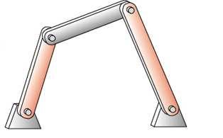
9 Link Classification Ground: fixed body w.r.t. frame of reference Crank: pivoted to ground, makes complete revolution Rocker: pivoted to ground, has oscillatory motion Coupler: link has complex motion, not attached to ground
10 Coupler?
11 Joints Joint:A connection between two or more links (at their nodes), which allows some motion, or potential motion, between the connected links. Joints: are called kinematic pairs can be classified as: By the type of contact between the elements, line, point, or surface. By the number of degrees of freedom allowed at the joint. By the type of physical closure of the joint: either force or form closed. By the number of links joined(order of the joint).
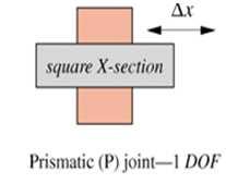
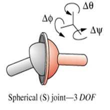
12 1. By Type of Contact Reuleaux s Classification Lower Pair:Surface Contact, Pin surrounded by a hole, block on a surface (slider), Revolute (R), Prismatic (P), Cylindrical (C), Screw (H), Higher Pair: Line and Point Contact Gear joint, Cam etc


13 Six Types of Lower Pair
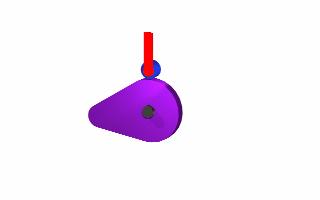
14 2. Joint Nomenclature Full joint, lower pairs-single degree of freedom Half joint, higher pair-two degrees of freedom

15 2. Number of DOF Full: 1-DOF or lower pair Rotating revolute (R) Translating Prismatic (P) Threaded nut Half: 2 DOF, Higher Pair Paradoxically called as Half Joint Roll slide joint Slippage Occurs
16 Ex. Joint Classification: Identify Full Joint & Half Joint

17 3. Formed and Forced
18 4. Joint Order Joint order = number of links-1
19 Kinematic chains, Mechanisms, Machines Kinematic Chain: An assemblage of links and joints, interconnected in a way to provide a controlled output motion in response to a supplied input motion. Mechanism: A kinematic chain in which at least one link has been "grounded," or attached, to the frame of reference (which itself may be in motion). Machine: A combination of resistant bodies arranged to compel the mechanical forces of nature to do work accompanied by determinate motions.

20 Kinematics Chain Links joined together for motion
21 Closed Chain If every link in the chain is connected to two or more links then the chain form one or more closed loops If the link form a closed loops, it is called closed kinematic chain If NOT, the chain is said to be open kinematics chain
22 Link Classification Links are classified as follows: Ground fixed w.r.t. reference frame Crank pivoted to ground, makes complete revolution Rocker pivoted to ground, has oscillatory motion Coupler -link has complex motion, not attached to ground
23 Planer and Spatial Mechanisms In a planar mechanisms, all of the relative motions of the rigid bodies are in one plane or in parallel planes Motion of such mechanism is called Coplanar If there is any relative motion that is not in the same plane or in parallel planes, the mechanism is called the spatial mechanism.
24 2.4 Determining Degree of Freedom The definition of the degrees of freedom of a mechanism is: The number of degrees of freedom of a mechanism is also called the mobility of the device
25 Planar Mechanisms
26 Degrees of Freedom Cont. 3 Degrees of Freedom (x, y, θ) 1 Degree of Freedom (θ) lower pair subtracts 2 degrees of freedom 1 Degree of Freedom (x) lower pair subtracts 2 degrees of freedom 2 Degrees of Freedom (x, θ) sliding contact subtracts 1 degree of freedom 0 Degrees of Freedom fixed to ground subtracts 3 degrees of freedom
27 Degrees of Freedom Cont. Different values of DOF mean different things. DOF = 0 Structure DOF < 0 Statically indeterminate structure DOF 1 Mobility is allowed
28 2.4 Determining Degree of Freedom For simple mechanisms calculating DOF is simple Open Mechanism DOF=3 Closed Mechanism DOF=1
29 Determining Degree of Freedom Gruebler s equation for planar mechanisms M =3L-2J-3G Where M =degree of freedom or mobility L = number of links J = number of joints (half joints count as 0.5) G = number of grounded links =1 This equation can be modified to be M =3(L-1)-2J
30 Determining Degree of Freedom Kutzbach s equation for planar mechanisms M = 3(L-1)-2J 1 -J 2 Where M = degree of freedom or mobility L = number of links J 1 = number of full joints 2 J = number of half joints For Spatial Mechanisms M = 6(L-1) -5J 1-4J 2-3J 3-2J 4 -J 5
31 Determining DOF (Examples) M=3(L-1)-2J 1 -J 2 Open Mechanism Closed Mechanism
32 Determining DOF(Examples) M=3(L-1)-2J 1 -J 2 L = 8 J = 10 DOF = 1
-2J 1 -J 2 L = 6 J = 7.")
33 Determining DOF (Examples) M=3(L-1)-2J 1 -J 2 L = 6 J = 7.5 DOF DOF = 0
34 2.5 Mechanisms and Structures Mechanism : DOF > 0 Structure : DOF =0 Preloaded Structure: DOF<0, may require force to assemble statically indeterminate

35 Quiz: Count number of links?
36 Spring as Link
37 2.6 Number Synthesis Reading Assignment Determination of the number and order of links and joints necessary to produce motion of a particular DOF Link Order: here means # of node per link i.e. binary, ternary, quaternary Book gives details
38 Number Synthesis Book gives details Total Links Binary Ternary Quaternary Pentagonal Hexagonal


39 2.7 Paradoxes Greublercriterion does not include geometry, so it can give wrong prediction Agree Greubler Equation DOF = 0 Usually when things are the same Gears: DOF = 1 Disagree Greubler Equation DOF = 1
40 2.8 Isomers A Greek word means having equal parts Refers to valid ways to assemble different types of links Only one valid fourbar isomer Two valid sixbar isomers Third one fails DOF test, as the DOF is not distributed over the linkage.
41 Fourbar Isomer Only way to construct a fourbar isomer is to have one binary link next to another binary link.
42 Watt s Sixbar Isomer One way to construct a sixbar isomer is to have the two ternary links attached.
43 Stephenson s Sixbar Isomer One way to construct a sixbar isomer is to have the two ternary links separated.
44 Invalid Sixbar Isomer This is an invalid isomer as the DOF is not distributed through the mechanism
45 Invalid Sixbar Isomer This is an invalid isomer as the DOF is not distributed through the mechanism This is a structure Effective link

46 2.10 Intermittent Motion It is a series of Motionsand Dwells Dwell: a period of time with no output motion while there is an input motion Examples: Geneva Mechanism, Linear Geneva Mechanism, Ratchet and Pawl

47 Geneva Mechanism
48 Linear Geneva Mechanism
49 Linear Geneva Mechanism

50 Ratchet and Pawl
51 2.11 Inversion Reading Assignment Created by grounding a different link in a kinematic chain Different behavior for different inversions
52 Three (3) Stephenson 6-bar inversions
53 Two (2) Watt s 6-bar inversions
54 2.12 Grashof Condition Fourbar linkage is simplest linkage with 1DOF
55 2.12 Grashof Condition Fourbar linkage is simplest linkage with 1-DOF Grashof condition predicts behavior of linkage based only on links length S = length of shortest link L = length of longest link P,Q=length of other two links If S + L P + Qthe linkage is Grashof with at least one link capable of making a complete rotation Otherwise the linkage is non-grashof with no link capable of making a complete rotation relative to ground
56 For case of S +L <P + Q Ground link adjacent to shortest => crank-rocker Ground shortest link => double crank Ground link opposite shortest link Grashof double rocker with shortest link capable of making a complete rotation
57 For the case of S +L >P +Q All inversions will be double rockers
58 For the case of S +L =P +Q According to the book, all inversions will be double cranks or crank rockers (true if S =P, L =Q) Indeterminate point when links are aligned (change points) Parallelogram form Deltoid form Anti parallelogram form
59 Barker s Complete Classification Type s+l vs p+q Inversion Class Barker s Designation Code Also Known as 1 < L 1 =s=ground I-1 Grashof crank-crank-crank GCCC double-crank 2 < L 2 =s=input I-2 Grashof crank-rocker-rocker GCRR crank-rocker 3 < L 3 =s=coupler I-3 Grashof rocker-crank-rocker GRCR double-rocker 4 < L 4 =s=output I-4 Grashof rocker-rocker-crank GRRC rocker-crank 5 > L 1 =l=ground II-1 Class 1 rocker-rocker-rocker RRR1 Triple-rocker 6 > L 2 =l= input II-2 Class 2 rocker-rocker-rocker RRR2 Triple-rocker 7 > L 3 =l= coupler II-3 Class 3 rocker-rocker-rocker RRR3 Triple-rocker 8 > L 4 =l= output II-4 Class 4 rocker-rocker-rocker RRR4 Triple-rocker 9 = L 1 =s=ground III-1 Change point crank-crank-crank SCCC SC double-crank 10 = L 2 =s=input III-2 Change point crank-rocker-rocker SCRR SC crank-rocker 11 = L 3 =s=coupler III-3 Change point rocker-crank-rocker SRCR SC double-rocker 12 = L 4 =s=output III-4 Change point rocker-rocker-crank SRRC SC rocker-crank Parallelogram or 13 = Two equal pairs III-5 Double change point S2X deltoid 14 = Taibah L University 1 =L 2 =L 3 =L 4 III-6 Triple change point S3X Square

60 2.13 Linkages of more than 4 bars 5-bar 2DOF Geared 5-bar 1DOF Provides for more complex motion Watt s sixbar 2 fourbar linkages in series Stephenson s sixbar 2 fourbar linkages in parallel


61 2.14 Springs as links Spring can act as a link to counteract static loads. Springs remove a degree of freedom (1 more equation) if they provided the right amount of force. Examples: car hood, desk arm lamp, garage door


62 2.15 Compliant Mechanisms Compliant link capable of significant deflection acts like a joint Also called a living hinge Advantage: simplicity, no assembly, little friction


63 2.17 Practical Consideration Revolute (Pin) Joints: Easy to build perfect pin joint.
64 Bearings
65 2.17 Practical Consideration
66 Eccentric crank
67 2.18 Motors and Drives Unless manually operated, a mechanism will require some type of driver device to provide the input motion and energy. Grashof linkage, slider-crank, and cam-follower, requires a continuous rotary input motion. Electric motors and gasoline/diesel engines are widely used to produce rotary input motion. Compressed air and pressurized hydraulic fluid are also used to power air and hydraulic motors. If the input motion is translation, as is common in earthmoving equipment, then a hydraulic or pneumatic cylinder is usually needed.

68 Electric Motors: The main electrical configuration division is: AC and DC. ACand DCrefer to alternating current and direct current The universal motor is designed to run on either ACor DC. Functional classificationsof electric motors: are gearmotors, servomotors, and stepping motors.
69 Electric Motors: DC MOTORS: made in different electrical configurations, such as permanent magnet (PM), shunt-wound, series-wound, and compound-wound. The names refer to the manner in which the rotating armature coils are electrically connected to the stationary field coils: -in parallel (shunt), in series, or in combined series-parallel (compound). Permanent magnets replace the field coils in a PM motor. Each configuration provides different torque-speed characteristics. The torque-speed curve of a motor describes how it will respond to an applied load. The torque-speed curve predicts how the mechanical-electrical system will behave when the load varies dynamically with time.


70
71 AC MOTORS AC MOTORS: least expensive and have variety of torque-speed curves to suit various load applications. Limited to a few standard speeds that are a function of the AC line frequency (60 Hz in North America, 50 Hz elsewhere). The synchronous motor speed n s is a function of line frequency f and the number of magnetic poles p present in the rotor. n s =120f/p Synchronous motors "lock on" to the AC line frequency and run exactly at synchronous speed. These motors are used for clocks and timers. Non-synchronous AC motors have a small amount of slip which makes them lag the line frequency by about 3 to 10%.


72
73 AC MOTORS The most common AC motors have 4 poles, giving nonsynchronous no-load speeds of about 1725 rpm, which reflects slippage from the 60-Hz synchronous speed of 1800 rpm. The single-phase shaded pole and permanent split capacitor designs have a starting torque lower than their full-load torque. To boost the start torque, the split-phase and capacitor-start designs employ a separate starting circuit that is cut off by a centrifugal switch as the motor approaches operating speed.
74 Air and Hydraulic Motors Air and Hydraulic motors have more limited application than electric motors. They require the availability of a compressed air or hydraulic source. Both are less energy efficient than the direct electrical to mechanical conversion of electric motors.
75 Air and Hydraulic Motors Air motors widely used in factories and shops. A common example is the air impact wrench used in automotive repair shops. Although individual air motors and air cylinders are relatively inexpensive, these pneumatic systems are quite expensive when the cost of all the ancillary equipment is included.

76 Air Motors Air motors
77 Air and Hydraulic Motors Hydraulic motors are most often found within machines or systems such as construction equipment (cranes), aircraft, and ships, where high-pressure hydraulic fluid is provided for many purposes. Hydraulic systems are very expensive when the cost of all the ancillary equipment is included. These are linear actuators (piston in cylinder) which provide a limited stroke, straight-linemotion output from a pressurized fluid flow input of either compressed air or hydraulic fluid.
78 Air and Hydraulic Cylinders Both have high cost, low efficiency, problem in control, and complication factors as listed under their air and hydraulic motor equivalents above. A linear actuator, when subjected to a constant pressure fluid source, typical of most compressors, will respond with more nearly constant acceleration, which means its velocity will increase linearly with time. This can result in severe impact loads on the driven mechanism when the actuator comes to the end of its stroke at maximum velocity.
79 Air and Hydraulic Cylinders Servo valve control of the fluid flow, to slow the actuator at the end of its stroke, is possible but is quite expensive. The most common application of fluid power cylinders is in form and construction equipment such as tractors and bulldozers, where open loop (non servo) hydraulic cylinders actuate the bucket or blade through linkages. The cylinder and its piston become two of the links (slider and track) in a slider-crank mechanism.
80 Solenoids Electromechanical (AC or DC) linear actuators similar to air cylinders. They are energy inefficient, are limited to very short strokes (about 2 to 3 cm), develop a force which varies exponentially over the stroke, and deliver high impact loads. They are, inexpensive, reliable, and have very rapid response times. They cannot handle much power, and typically used as control or switching devices rather than as devices which do large amounts of work on a system. A common application of solenoids is in camera shutters, where a small solenoid is used to pull the latch and trip the shutter action when you push the button to take the picture. Its nearly instantaneous response is an asset in this application, and very little work is being done in tripping a latch. Another application is in electric door or trunk locking systems in automobiles, where the click of their impact can be clearly heard when you turn the key (or press the button) to lock or unlock the mechanism.
81 Assignment:
Theory of Machines Course # 1
 Theory of Machines Course # 1 Ayman Nada Assistant Professor Jazan University, KSA. arobust@tedata.net.eg March 29, 2010 ii Sucess is not coming in a day 1 2 Chapter 1 INTRODUCTION 1.1 Introduction Mechanisms
Modelling of mechanical system CREATING OF KINEMATIC CHAINS
 Modelling of mechanical system CREATING OF KINEMATIC CHAINS Mechanism Definitions 1. a system or structure of moving parts that performs some function 2. is each system reciprocally joined moveable bodies
ME 321 Kinematics and Dynamics of Machines
 .0 INTRODUCTION ME Kinematics and Dynamics of Machines All Text References in these notes are for: Mechanism Design: Analysis and Synthesis, Volume, Fourth Edition, Erdman, Sandor and Kota, Prentice-Hall,
Chapter 1 Introduction
 Chapter 1 Introduction Generally all considerations in the force analysis of mechanisms, whether static or dynamic, the links are assumed to be rigid. The complexity of the mathematical analysis of mechanisms
KINEMATICS OF MACHINES. Dr.V.SUNDARESWARAN PROFESSOR OF MECHANICAL ENGG. COLLEGE OF ENGINEERING, GUINDY ANNA UNIVERSITY CHENNAI
 KINEMATICS OF MACHINES Dr.V.SUNDARESWARAN PROFESSOR OF MECHANICAL ENGG. COLLEGE OF ENGINEERING, GUINDY ANNA UNIVERSITY CHENNAI 600 025 MECHANICS Science dealing with motion DIVISIONS OF MECHANICS Statics
Kinematics: Intro. Kinematics is study of motion
 Kinematics is study of motion Kinematics: Intro Concerned with mechanisms and how they transfer and transform motion Mechanisms can be machines, skeletons, etc. Important for CG since need to animate complex
SAMPLE STUDY MATERIAL. Mechanical Engineering. Postal Correspondence Course. Theory of Machines. GATE, IES & PSUs
 TOM - ME GATE, IES, PSU 1 SAMPLE STUDY MATERIAL Mechanical Engineering ME Postal Correspondence Course Theory of Machines GATE, IES & PSUs TOM - ME GATE, IES, PSU 2 C O N T E N T TOPIC 1. MACHANISMS AND
Kinematics Fundamentals CREATING OF KINEMATIC CHAINS
 Kinematics Fundamentals CREATING OF KINEMATIC CHAINS Mechanism Definitions 1. a system or structure of moving parts that performs some function 2. is each system reciprocally joined moveable bodies the
September 20, Chapter 5. Simple Mechanisms. Mohammad Suliman Abuhaiba, Ph.D., PE
 Chapter 5 Simple Mechanisms 1 Mohammad Suliman Abuhaiba, Ph.D., PE 2 Assignment #1 All questions at the end of chapter 1 st Exam: Saturday 29/9/2018 3 Kinematic Link or Element kinematic link (link) or
Chapter 4. Mechanism Design and Analysis
 Chapter 4. Mechanism Design and Analysis All mechanical devices containing moving parts are composed of some type of mechanism. A mechanism is a group of links interacting with each other through joints
WEEKS 1-2 MECHANISMS
 References WEEKS 1-2 MECHANISMS (METU, Department of Mechanical Engineering) Text Book: Mechanisms Web Page: http://www.me.metu.edu.tr/people/eres/me301/in dex.ht Analitik Çözümlü Örneklerle Mekanizma
Mechanics Place in Science Mechanisms and Structures Number Synthesis Paradoxes and Isomers Transformations and Inversions Grashof s Law
 INTODUCTION TO MECHANISM SYNTHESIS Mechanics Place in Science Mechanisms and Structures Number Synthesis Paradoxes and Isomers Transformations and Inversions Grashof s Law ME312: Dynamics of Mechanisms
The hood (3) is linked to the body (1) through two rocker links (2 and 4).
 is linked to the body (1) through two rocker links (2 and 4).") DESIGN OF MACHINERY - th Ed SOLUTION MANUAL -- PROBLEM - Find three (or other number as assigned) of the following common devices. Sketch careful kinematic diagrams and find their total degrees of freedom.
DESIGN OF MACHINERY - th Ed SOLUTION MANUAL -- PROBLEM - Find three (or other number as assigned) of the following common devices. Sketch careful kinematic diagrams and find their total degrees of freedom.
Kinematics of Machines. Brown Hills College of Engineering & Technology
 Introduction: mechanism and machines, kinematic links, kinematic pairs, kinematic chains, plane and space mechanism, kinematic inversion, equivalent linkages, four link planar mechanisms, mobility and
Mechanism. Mechanism consists of linkages and joints.
 Mechanism Machines are mechanical devices used to accomplish work. A mechanism is a heart of a machine. It is the mechanical portion of the machine that has the function of transferring motion and forces
Mechanisms. Updated: 18Apr16 v7
 Mechanisms Updated: 8Apr6 v7 Mechanism Converts input motion or force into a desired output with four combinations of input and output motion Rotational to Oscillating Rotational to Rotational Rotational
Analytical and Applied Kinematics
 Analytical and Applied Kinematics Vito Moreno moreno@engr.uconn.edu 860-614-2365 (cell) http://www.engr.uconn.edu/~moreno Office EB1, hours Thursdays 10:00 to 5:00 1 This course introduces a unified and
Overview. What is mechanism? What will I learn today? ME 311: Dynamics of Machines and Mechanisms Lecture 2: Synthesis
 Overview ME 311: Dynamics of Machines and Mechanisms Lecture 2: Synthesis By Suril Shah Some fundamentals Synthesis Function, path and motion generation Limiting condition Dimensional synthesis 1 2 What
MACHINES AND MECHANISMS
 MACHINES AND MECHANISMS APPLIED KINEMATIC ANALYSIS Fourth Edition David H. Myszka University of Dayton PEARSON ж rentice Hall Pearson Education International Boston Columbus Indianapolis New York San Francisco
2.007 Design and Manufacturing I Spring 2009
 MIT OpenCourseWare http://ocw.mit.edu 2.007 Design and Manufacturing I Spring 2009 For information about citing these materials or our Terms of Use, visit: http://ocw.mit.edu/terms. 2.007 Design and Manufacturing
Computational Design + Fabrication: 4D Analysis
 Computational Design + Fabrication: 4D Analysis Jonathan Bachrach EECS UC Berkeley October 6, 2015 Today 1 News Torque and Work Simple Machines Closed Chains Analysis Paper Review Lab 3 Critique News 2
CHAPTER 1 : KINEMATICS
 KINEMATICS : It relates to the study of the relative motion between the parts of a machine. Let us consider a reciprocating engine, in this the piston is made to reciprocate in the cylinderdue to the applied
Lesson 1: Introduction to Pro/MECHANICA Motion
 Lesson 1: Introduction to Pro/MECHANICA Motion 1.1 Overview of the Lesson The purpose of this lesson is to provide you with a brief overview of Pro/MECHANICA Motion, also called Motion in this book. Motion
SolidWorks Assembly Files. Assemblies Mobility. The Mating Game Mating features. Mechanical Mates Relative rotation about axes
 Assemblies Mobility SolidWorks Assembly Files An assembly file is a collection of parts The first part brought into an assembly file is fixed Other parts are constrained relative to that part (or other
Mechanism Synthesis Rules
 Mechanism Synthesis ules Linkage Transformation ules Grashof s Law Inversion ME312: Dynamics of Mechanisms 1 BB LINKAGE TANSFOMATION ULE 1 evolute joints in any loop can be replaced by prismatic joints
2.1 Introduction. 2.2 Degree of Freedom DOF of a rigid body
 Chapter 2 Kinematics 2.1 Introduction 2.2 Degree of Freedom 2.2.1 DOF of a rigid body In order to control and guide the mechanisms to move as we desired, we need to set proper constraints. In order to
Position Analysis
 Position Analysis 2015-03-02 Position REVISION The position of a point in the plane can be defined by the use of a position vector Cartesian coordinates Polar coordinates Each form is directly convertible
Kinematics of Machines Prof. A. K. Mallik Department of Mechanical Engineering Indian Institute of Technology, Kanpur. Module 10 Lecture 1
 Kinematics of Machines Prof. A. K. Mallik Department of Mechanical Engineering Indian Institute of Technology, Kanpur Module 10 Lecture 1 So far, in this course we have discussed planar linkages, which
Mechanical structure of a robot=skeleton of human body Study of structure of a robot=physical structure of the manipulator structure
 UNIT I FUNDAMENTALS OF ROBOT Part A 1. Define Robot. An industrial robot is a re-programmable, multifunctional manipulator designed to move materials, parts, tools, or specialized devices through variable
PROBLEMS AND EXERCISES PROBLEMS
 64 Fundamentals of Kinematics and Dynamics of Machines and Mechanisms PROBLEMS AND EXERCISES PROBLEMS 1. In Figure 1.14c an inverted slider-crank mechanism is shown. b. If the input is the displacement
Manipulator Path Control : Path Planning, Dynamic Trajectory and Control Analysis
 Manipulator Path Control : Path Planning, Dynamic Trajectory and Control Analysis Motion planning for industrial manipulators is a challenging task when obstacles are present in the workspace so that collision-free
MENG 372 Chapter 3 Graphical Linkage Synthesis. All figures taken from Design of Machinery, 3 rd ed. Robert Norton 2003
 MENG 372 Chapter 3 Graphical Linkage Synthesis All figures taken from Design of Machinery, 3 rd ed. Robert Norton 2003 1 Introduction Synthesis: to design or create a mechanism to give a certain motion
MECHANICAL ENGINEERING
 MECHANICAL ENGINEERING ESE TOPICWISE OBJECTIVE SOLVED PAPER-II FROM (1995-2018) UPSC Engineering Services Examination State Engineering Service Examination & Public Sector Examination. IES MASTER PUBLICATION
Kinematics of Machines Prof. A. K. Mallik Department of Mechanical Engineering Indian Institute of Technology, Kanpur. Module - 3 Lecture - 1
 Kinematics of Machines Prof. A. K. Mallik Department of Mechanical Engineering Indian Institute of Technology, Kanpur Module - 3 Lecture - 1 In an earlier lecture, we have already mentioned that there
Manipulation and Fluid Power. October 07, 2008
 2008 TE Sessions Supported by Manipulation and Fluid Power October 07, 2008 www.robojackets.org Manipulation Keys to Understanding Manipulators What is a manipulator? What kinds of manipulators are there?
Session #5 2D Mechanisms: Mobility, Kinematic Analysis & Synthesis
 Session #5 2D Mechanisms: Mobility, Kinematic Analysis & Synthesis Courtesy of Design Simulation Technologies, Inc. Used with permission. Dan Frey Today s Agenda Collect assignment #2 Begin mechanisms
10/25/2018. Robotics and automation. Dr. Ibrahim Al-Naimi. Chapter two. Introduction To Robot Manipulators
 Robotics and automation Dr. Ibrahim Al-Naimi Chapter two Introduction To Robot Manipulators 1 Robotic Industrial Manipulators A robot manipulator is an electronically controlled mechanism, consisting of
 Homework 1 - Grade - ME-3610-001 - Dynamics of Machinery - Tennessee Technologic... Page 1 of 21 My Home Email Calendar Logged in as scanfield 9/26/2011 ME-3610-001 - Dynamics of Machinery Course Home
Position and Displacement Analysis
 Position and Displacement Analysis Introduction: In this chapter we introduce the tools to identifying the position of the different points and links in a given mechanism. Recall that for linkages with
Mechanical Electrical Digital
 Mechatronics I: Mechanical Systems Richard Voyles Week 1 Based on notes from Paul Rullkoetter Mechatronic Systems Mechanical Structure Actuats Senss Transducers DAC ADC Computer Digital Processing Element
Solutions to Chapter 6 Exercise Problems A 1 O 4 B 2
 Solutions to Chapter 6 Exercise Problems Problem 6.1: Design a double rocker, four-bar linkage so that the base link is 2-in and the output rocker is 1-in long. The input link turns counterclockwise 60
Kinematic Synthesis. October 6, 2015 Mark Plecnik
 Kinematic Synthesis October 6, 2015 Mark Plecnik Classifying Mechanisms Several dichotomies Serial and Parallel Few DOFS and Many DOFS Planar/Spherical and Spatial Rigid and Compliant Mechanism Trade-offs
MAE 342 Dynamics of Machines. Types of Mechanisms. type and mobility
 MAE 342 Dynamics of Machines Types of Mechanisms Classification of Mechanisms by type and mobility MAE 342 Dynamics of Machines 2 Planar, Spherical and Spatial Mechanisms Planar Mechanisms: all points
Industrial Robots : Manipulators, Kinematics, Dynamics
 Industrial Robots : Manipulators, Kinematics, Dynamics z z y x z y x z y y x x In Industrial terms Robot Manipulators The study of robot manipulators involves dealing with the positions and orientations
A rigid body free to move in a reference frame will, in the general case, have complex motion, which is simultaneously a combination of rotation and
 050389 - Analtical Elements of Mechanisms Introduction. Degrees of Freedom he number of degrees of freedom (DOF) of a sstem is equal to the number of independent parameters (measurements) that are needed
User s Guide WATT 1.5. Heron Technologies bv P.O.Box AA Hengelo The Netherlands
 WATT 1.5 Heron Technologies bv P.O.Box 2 7550 AA Hengelo The Netherlands 1 Proprietary notice Heron Technologies bv, owns both this software program and its documentation. Both the program and the documentation
Lecture Note 2: Configuration Space
 ECE5463: Introduction to Robotics Lecture Note 2: Configuration Space Prof. Wei Zhang Department of Electrical and Computer Engineering Ohio State University Columbus, Ohio, USA Spring 2018 Lecture 2 (ECE5463
DESIGN AND ANALYSIS OF WEIGHT SHIFT STEERING MECHANISM BASED ON FOUR BAR MECHANISM
 International Journal of Mechanical Engineering and Technology (IJMET) Volume 8, Issue 12, December 2017, pp. 417 424, Article ID: IJMET_08_12_041 Available online at http://www.iaeme.com/ijmet/issues.asp?jtype=ijmet&vtype=8&itype=12
Kinematics of Machines Prof. A. K. Mallik Department of Mechanical Engineering Indian Institute of Technology, Kanpur. Module - 2 Lecture - 1
 Kinematics of Machines Prof. A. K. Mallik Department of Mechanical Engineering Indian Institute of Technology, Kanpur Module - 2 Lecture - 1 The topic of today s lecture is mobility analysis. By mobility
Mechanism and Robot Kinematics, Part I: Algebraic Foundations
 Mechanism and Robot Kinematics, Part I: Algebraic Foundations Charles Wampler General Motors R&D Center In collaboration with Andrew Sommese University of Notre Dame Overview Why kinematics is (mostly)
Homework 4 PROBLEMS ON THREE POSITION GUIDANCE
 Homework 4 ROLEMS ON THREE OSITION GUIDNE. In the synthesis of three positions of a plane by a four-bar mechanism, in the graphical method and were selected arbitrarily and, were determined as the corresponding
1.9 Snap Action Mechanisms 19
 Theory of Mechanism and Machines Chapter- Introduction Prepared y rij hooshan sst. Professor. S.. College of Engg. nd Technology Mathura, Uttar Pradesh, (India) Supported y: Purvi hooshan In This Chapter
Reaching and Grasping
 Lecture 14: (06/03/14) Reaching and Grasping Reference Frames Configuration space Reaching Grasping Michael Herrmann michael.herrmann@ed.ac.uk, phone: 0131 6 517177, Informatics Forum 1.42 Robot arms Typically
SYSTEMS ELECTRONICS GROUP
 SYSTEMS ELECTRONICS GROUP SYSTEMS M4500 MACHINE COMPONENTS RSV34-MS1 RESOLVER with MS CONNECTOR Brushless, Single-turn Resolver Rated to 3,000 RPM Rotary Position Transducer for M4500, M4020, M4040, M4041,
ME 115(b): Final Exam, Spring
: Final Exam, Spring") ME 115(b): Final Exam, Spring 2005-06 Instructions 1. Limit your total time to 5 hours. That is, it is okay to take a break in the middle of the exam if you need to ask me a question, or go to dinner,
ME 115(b): Final Exam, Spring 2005-06 Instructions 1. Limit your total time to 5 hours. That is, it is okay to take a break in the middle of the exam if you need to ask me a question, or go to dinner,
NOT COMPLETE. θ 4 B 2 = O 2 O 4 = A 2 = A 1 B 1 O 2 KINEMATIC SYNTHESIS
 ME 35 NOT COMPLETE Design Design a crank-rocker four-bar (Grashof) where the input link rotates completely and the output link (the follower) rocks back and forth with a prescribed angle The design requires
Mechanism Design. Four-bar coupler-point curves
 Mechanism Design Four-bar coupler-point curves Four-bar coupler-point curves A coupler is the most interesting link in any linkage. It is in complex motion, and thus points on the coupler can have path
INSTITUTE OF AERONAUTICAL ENGINEERING
 Name Code Class Branch Page 1 INSTITUTE OF AERONAUTICAL ENGINEERING : ROBOTICS (Autonomous) Dundigal, Hyderabad - 500 0 MECHANICAL ENGINEERING TUTORIAL QUESTION BANK : A7055 : IV B. Tech I Semester : MECHANICAL
Mechanism Simulation With Working Model
 Mechanism Simulation With Working Model Shih-Liang Wang Department of Mechanical Engineering North Carolina A&T State University Greensboro, NC 27411 Introduction Kinematics is a study of motion and force
MACHINE THEORY Bachelor in Mechanical Engineering INTRODUCTION TO MACHINE DESIGN
 MACHINE THEORY Bachelor in Mechanical Engineering INTRODUCTION TO MACHINE DESIGN Ignacio Valiente Blanco José Luis Pérez Díaz David Mauricio Alba Lucero Efrén Díez Jiménez Timm Lauri Berit Sanders Machine
 We will use point A as the reference point to find VB because A is in the same link as Band we have already solved for VA- Any vector equation can be solved for two unknowns. Each term has two parameters,
Using RecurDyn. Contents
 Using RecurDyn Contents 1.0 Multibody Dynamics Overview... 2 2.0 Multibody Dynamics Applications... 3 3.0 What is RecurDyn and how is it different?... 4 4.0 Types of RecurDyn Analysis... 5 5.0 MBD Simulation
11. Kinematic models of contact Mechanics of Manipulation
 11. Kinematic models of contact Mechanics of Manipulation Matt Mason matt.mason@cs.cmu.edu http://www.cs.cmu.edu/~mason Carnegie Mellon Lecture 11. Mechanics of Manipulation p.1 Lecture 11. Kinematic models
Lecture 3. Planar Kinematics
 Matthew T. Mason Mechanics of Manipulation Outline Where are we? s 1. Foundations and general concepts. 2.. 3. Spherical and spatial kinematics. Readings etc. The text: By now you should have read Chapter
SYNTHESIS OF PLANAR MECHANISMS FOR PICK AND PLACE TASKS WITH GUIDING LOCATIONS
 Proceedings of the ASME 2013 International Design Engineering Technical Conferences and Computers and Information in Engineering Conference IDETC/CIE 2013 August 4-7, 2013, Portland, Oregon, USA DETC2013-12021
Basilio Bona ROBOTICA 03CFIOR 1
 Kinematic chains 1 Readings & prerequisites Chapter 2 (prerequisites) Reference systems Vectors Matrices Rotations, translations, roto-translations Homogeneous representation of vectors and matrices Chapter
Kinematics - Introduction. Robotics. Kinematics - Introduction. Vladimír Smutný
 Kinematics - Introduction Robotics Kinematics - Introduction Vladimír Smutný Center for Machine Perception Czech Institute for Informatics, Robotics, and Cybernetics (CIIRC) Czech Technical University
INTERNATIONAL JOURNAL OF DESIGN AND MANUFACTURING TECHNOLOGY (IJDMT)
") INTERNATIONAL JOURNAL OF DESIGN AND MANUFACTURING TECHNOLOGY (IJDMT) International Journal of Design and Manufacturing Technology (IJDMT), ISSN 0976 6995(Print), ISSN 0976 6995 (Print) ISSN 0976 7002 (Online)
INTERNATIONAL JOURNAL OF DESIGN AND MANUFACTURING TECHNOLOGY (IJDMT) International Journal of Design and Manufacturing Technology (IJDMT), ISSN 0976 6995(Print), ISSN 0976 6995 (Print) ISSN 0976 7002 (Online)
Engineering Mechanics. Equilibrium of Rigid Bodies
 Engineering Mechanics Equilibrium of Rigid Bodies System is in equilibrium if and only if the sum of all the forces and moment (about any point) equals zero. Equilibrium Supports and Equilibrium Any structure
MC-E - Motion Control
 IDC Technologies - Books - 1031 Wellington Street West Perth WA 6005 Phone: +61 8 9321 1702 - Email: books@idconline.com MC-E - Motion Control Price: $139.94 Ex Tax: $127.22 Short Description This manual
Analysis of a 4 Bar Crank-Rocker Mechanism Using COSMOSMotion
 Analysis of a 4 Bar Crank-Rocker Mechanism Using COSMOSMotion ME345: Modeling and Simulation Professor Frank Fisher Stevens Institute of Technology Last updated: June 29th, 2009 Table of Contents 1. Introduction
Human Motion. Session Speaker Dr. M. D. Deshpande. AML2506 Biomechanics and Flow Simulation PEMP-AML2506
 AML2506 Biomechanics and Flow Simulation Day 02A Kinematic Concepts for Analyzing Human Motion Session Speaker Dr. M. D. Deshpande 1 Session Objectives At the end of this session the delegate would have
Introduction to Solid Modeling Using SolidWorks 2008 COSMOSMotion Tutorial Page 1
 Introduction to Solid Modeling Using SolidWorks 2008 COSMOSMotion Tutorial Page 1 In this tutorial, we will learn the basics of performing motion analysis using COSMOSMotion. Although the tutorial can
The Design and Simulation of Mechanisms. Inna Sharifgalieva
 The Design and Simulation of Mechanisms Inna Sharifgalieva Degree Thesis Degree Programme: Materials Processing Technology 2014 2018 1 DEGREE THESIS Arcada University of Applied Sciences Degree Programme:
Robotics (Kinematics) Winter 1393 Bonab University
 Winter 1393 Bonab University") Robotics () Winter 1393 Bonab University : most basic study of how mechanical systems behave Introduction Need to understand the mechanical behavior for: Design Control Both: Manipulators, Mobile Robots
Robotics () Winter 1393 Bonab University : most basic study of how mechanical systems behave Introduction Need to understand the mechanical behavior for: Design Control Both: Manipulators, Mobile Robots
Definitions. Kinematics the study of constrained motion without regard to forces that cause that motion
 Notes_0_0 of efinitions Kinematics the stud of constrained motion without regard to forces that cause that motion namics the stud of how forces cause motion ausalit the relationship between cause and effect
ROBOTICS 01PEEQW. Basilio Bona DAUIN Politecnico di Torino
 ROBOTICS 01PEEQW Basilio Bona DAUIN Politecnico di Torino Kinematic chains Readings & prerequisites From the MSMS course one shall already be familiar with Reference systems and transformations Vectors
CUSTOMIZED TEACHER ASSESSMENT BLUEPRINT. Test Code: 5936 Version: 01
 CUSTOMIZED TEACHER ASSESSMENT BLUEPRINT ELECTROMECHANICAL ENGINEERING TECHNOLOGY PA Test Code: 5936 Version: 01 Specific competencies and skills tested in this assessment: Technical Documentation and Safety
A survey paper on a factors affecting on selection of mechanical gripper
 2014 IJEDR Volume 2, Issue 1 ISSN: 2321-9939 A survey paper on a factors affecting on selection of mechanical gripper 1 Vinayak D. Latake, 2 Dr. V.M.Phalle 1 PG Scholar, 2 AssociateProfessor Department
A MECHATRONIC APPROACH OF THE WINDSHIELD WIPER MECHANISMS
 A MECHATRONIC APPROACH OF THE WINDSHIELD WIPER MECHANISMS Alexandru Cătălin Transilvania University of Braşov calex@unitbv.ro Keywords: windshield wiper mechanism, dynamic simulation, control system, virtual
Simulation-Based Design of Robotic Systems
 Simulation-Based Design of Robotic Systems Shadi Mohammad Munshi* & Erik Van Voorthuysen School of Mechanical and Manufacturing Engineering, The University of New South Wales, Sydney, NSW 2052 shadimunshi@hotmail.com,
Quick Start Training Guide
 Quick Start Training Guide Table of Contents 1 INTRODUCTION TO MAPLESIM... 5 1.1 USER INTERFACE... 5 2 WORKING WITH A SAMPLE MODEL... 7 2.1 RUNNING A SIMULATION... 7 2.2 GRAPHICAL OUTPUT... 7 2.3 3D VISUALIZATION...
Design Optimization of Power Manipulator Gripper for Maximum Grip Force
 Design Optimization of Power Manipulator Gripper for Maximum Grip Force Uma B Baliga Mechanical Engineering Department Karavali Institute of Technology Mangalore, India S Joseph Winston, SO-F Department
Chapter 1: Introduction
 Chapter 1: Introduction This dissertation will describe the mathematical modeling and development of an innovative, three degree-of-freedom robotic manipulator. The new device, which has been named the
CONSIDERATIONS REGARDING LINKAGES USED FOR SHAFTS COUPLING
 Mechanical Testing and Diagnosis ISSN 2247 9635, 2012 (II), Volume 4, 19-27 CONSIDERATIONS REGARDING LINKAGES USED FOR SHAFTS COUPLING Stelian ALACI, Florina Carmen CIORNEI, Constantin FILOTE, Luminiţa
COPYRIGHTED MATERIAL INTRODUCTION CHAPTER 1
 CHAPTER 1 INTRODUCTION Modern mechanical and aerospace systems are often very complex and consist of many components interconnected by joints and force elements such as springs, dampers, and actuators.
Computer Aided Kinematic Analysis of Toggle Clamping Mechanism
 IOSR Journal of Mechanical & Civil Engineering (IOSRJMCE) e-issn: 2278-1684,p-ISSN: 2320-334X PP 49-56 www.iosrjournals.org Computer Aided Kinematic Analysis of Toggle Clamping Mechanism S.A. Bhojne 1,
Lecture VI: Constraints and Controllers
 Lecture VI: Constraints and Controllers Motion Constraints In practice, no rigid body is free to move around on its own. Movement is constrained: wheels on a chair human body parts trigger of a gun opening
Module 1 : Introduction to robotics. Lecture 3 : Industrial Manipulators & AGVs. Objectives. History of robots : Main bodies and wrists
 Module 1 : Introduction to robotics Lecture 3 : Industrial Manipulators & AGVs Objectives In this course you will learn the following History of development of robots. Main body types of manipulators with
Lecture Note 2: Configuration Space
 ECE5463: Introduction to Robotics Lecture Note 2: Configuration Space Prof. Wei Zhang Department of Electrical and Computer Engineering Ohio State University Columbus, Ohio, USA Spring 2018 Lecture 2 (ECE5463
Motion Simulation and Mechanism Design with SOLIDWORKS Motion 2017
 Motion Simulation and Mechanism Design with SOLIDWORKS Motion 2017 Kuang-Hua Chang Ph.D. SDC P U B L I C AT I O N S Better Textbooks. Lower Prices. www.sdcpublications.com Powered by TCPDF (www.tcpdf.org)
RYOBI 10 in. (254 mm) TABLE SAW - MODEL NO. BTS20
 TABLE SAW - MODEL NO. BTS20") A0 OUTFEED SUPPORT RYOBI in. ( mm) TABLE SAW - MODEL NO. BTS0 FIGURE B: OUTFEED SUPPORT 0 OUTFEED SUPPORT... 0 SCREW (/-0 x / in.)... 00 OUTFEED SUPPORT ROD... 00 STOP SCREW (M X mm)... FIGURE C: BLADE
A0 OUTFEED SUPPORT RYOBI in. ( mm) TABLE SAW - MODEL NO. BTS0 FIGURE B: OUTFEED SUPPORT 0 OUTFEED SUPPORT... 0 SCREW (/-0 x / in.)... 00 OUTFEED SUPPORT ROD... 00 STOP SCREW (M X mm)... FIGURE C: BLADE
Effect of change of the orientation of dyad links on kinematics of Stephenson-III six-bar linkage
 Effect of change of the orientation of dyad links on kinematics of Stephenson-III six-bar linkage Tanmay Agrawal, Kushagra Upadhyay, Nitin Sharma and Rakesh Sehgal* Department of Mechanical Engineering
Lecture Note 6: Forward Kinematics
 ECE5463: Introduction to Robotics Lecture Note 6: Forward Kinematics Prof. Wei Zhang Department of Electrical and Computer Engineering Ohio State University Columbus, Ohio, USA Spring 2018 Lecture 6 (ECE5463
Inherently Balanced Double Bennett Linkage
 Inherently Balanced Double Bennett Linkage V. van der Wijk Delft University of Technology - Dep. of Precision and Microsystems Engineering Mechatronic System Design, e-mail: v.vanderwijk@tudelft.nl Abstract.
Animations in Creo 3.0
 Animations in Creo 3.0 ME170 Part I. Introduction & Outline Animations provide useful demonstrations and analyses of a mechanism's motion. This document will present two ways to create a motion animation
SUPPORTING LINEAR MOTION: A COMPLETE GUIDE TO IMPLEMENTING DYNAMIC LOAD SUPPORT FOR LINEAR MOTION SYSTEMS
 SUPPORTING LINEAR MOTION: A COMPLETE GUIDE TO IMPLEMENTING DYNAMIC LOAD SUPPORT FOR LINEAR MOTION SYSTEMS Released by: Keith Knight Catalyst Motion Group Engineering Team Members info@catalystmotiongroup.com
MECHATRONICS. William Bolton. Sixth Edition ELECTRONIC CONTROL SYSTEMS ENGINEERING IN MECHANICAL AND ELECTRICAL PEARSON
 MECHATRONICS ELECTRONIC CONTROL SYSTEMS IN MECHANICAL AND ELECTRICAL ENGINEERING Sixth Edition William Bolton PEARSON Harlow, England London New York Boston San Francisco Toronto Sydney Auckland Singapore
Electropneumatics Basic Level Textbook TP 201
 Electropneumatics Basic Level Textbook TP 201 Festo Didactic 091181 en Order No.: 091181 Edition: 07/2004 Author: F. Ebel, G. Prede, D. Scholz Graphics: Doris Schwarzenberger Layout: 19.07.04, Susanne
Kinematic and Dynamic Analysis of Stephenson Six Bar Mechanism Using HyperWorks
 Kinematic and Dynamic Analysis of Stephenson Six Bar Mechanism Using HyperWorks Kailash Chaudhary Phd Scholar Malaviya National Institute of Technology,Jaipur JLN Marg, Jaipur - 302 017, India Dr. Himanshu