Electric Vehicle Display
|
|
|
- Kelly Owens
- 6 years ago
- Views:
Transcription
1 Electric Vehicle Display Feb , Dilithium Design, LLC
2 Contents Overview... 3 Installation... 4 Mechanical... 4 Systems Connector... 5 Analog Fuel Gauge... 6 Hall Connector... 6 State of Charge Calculation... 7 Voltage SoC... 7 Charge SoC... 7 Screens... 8 Startup Screen... 8 Toobar... 8 Back Icon... 8 Setup Icon... 8 EVCC Status... 8 BMSC Status... 8 Status Screen... 9 Cell Map Cell Voltages BMSC Status Configuration SOC Configuration EVCC Configuration BMSC Configuration Charging Charge Progress Charge History Display Quick Start Warrantee and Support Document History

3 Overview The Dilithium Design Electric Vehicle Display displays pack State of Charge, Pack Current and Voltage Measurements, Cell Status, Pack Status, and individual cell voltages. The Display uses the Dilithium Design Battery Management System. The Display can configure most BMS parameters. Up to four BMS Controllers may be managed by a single Display; cells may be organized in up to four parallel packs. The Display can optionally be used with the Thunderstruck EVCC (Electric Vehicle Charge Controller). The Display can configure most EVCC parameters, monitors the J1772 plug and charging status, and can show the EVCC charge history. The Display computes Pack State of Charge in two ways: by estimation from BMS Cell Voltage Statistics, and by charge counting using an optional Current Sensor. The Display also supports an optional analog Fuel Gauge. Figure 1 EV Display System Diagram BMS documentation is provided in Battery Management System v2.0, EVCC documentation is provided in EV Charger Controller v2.4, 3


4 Installation Mechanical The Display hardware uses the 4D systems gen4 32-DCT-CLB. This display is a x320 pixel LCD capacitive touch display with an attached bezel. The datasheet can be found at With bezel, the display measures 98.8mm x 72.6mm. The display is mounted on a flat surface with a rectangular opening (approximately 80mm x 56mm) and affixed to the surface using double-sided tape. Mechanical drawings can be found at CLB/downloads/gen4-uLCD-32D-CLB_drawing_R_1_0.PDF A PCB is mounted directly on the back of the display and connects to the display using a 30pin flat cable. The PCB has two connectors: a 5-pin Systems connector and a 4-pin Hall connector. When mounting the display, the 5-pin Systems connector is towards the bottom. Figure 2 Display Hardware The System and Hall connectors use push-in connectors. These connectors accept gauge stranded or solid wire; stranded 20 gauge wire is recommended. To make a connection, strip the wire back ½. Twist the wire end and insert. Be sure that all strands of wire get correctly inserted to prevent shorting between adjacent wires. 4


5 Figure 3 Push-in Connector Removing the wire from the connector requires a removal tool: insert the tool into the associated slot above the wire and wiggle it in. This will collapse the spring holding the wire and the wire can be removed. The wire header part numbers are 5p Systems Connector Harting p Hall Connector Harting The removal tool is Harting Alternately, the Molex KK terminal removal tool, part number W-HT-1884, is widely available and has been found to work well. Systems Connector The System Connector provides 12V power, CAN, and the analog gauge sender connection. gnd +12V CANL CANH gauge Figure 4 Systems Connector Pinout The gnd and +12V inputs on the System Connector provide Display power. Power should be enabled when the EV is being driven or being charged. Maximum 12V power consumption is approximately 100ma. If the Thunderstruck EVCC is being used, display power may be provided directly from the EVCC 12V_SW output. The CANL and CANH inputs connect to the EV CAN network. A CAN termination resistor in the Display may be enabled by installing the bridge between the right two pins of jumper JP3. This jumper is adjacent the 5p Systems Connector. Figure 4 CAN Termination Jumper 5


6 See BMS documentation for CAN wiring guidelines. The gauge output connects directly to the sender input on an analog fuel gauge. Analog Fuel Gauge Analog Fuel gauges typically have three connections: +12V, Ground, and sender. Figure 5 - Analog Fuel Gauge Connections Note that the Ground connection on the meter might be indicated by -, or by a symbol: Connect EV +12V and Ground to the gauge, and connect the gauge sender connection to the Display gauge output on the Systems Connector. Conventionally, the Fuel Gauge is connected to a gas tank float sender : a variable resistor which changes resistance based on the level of the float. Usually this connection only uses one wire as the return connection is made directly to chassis ground. The Display has been tested with a variety of fuel gauges, including VDO and Bosch. The fuel gauge and the sender are a matched set, there are common values, there are no standard ones. The Display uses Pulse Width Modulation (PWM) to drive the meter. In order to accommodate the different fuel gauges, the PWM settings must be configured in the Display for the gauge to work properly. See SOC Configuration, below. Hall Connector The Display supports LEM HTFS Hall sensors. These sensors are single range, bidirectional sensors that come in several models: HTFS-200, -400, -600, and -800, and current ranges: +/- 300A, +/- 600A, +/- 900A, and +/- 1200A. Vref Vout gnd +5 Figure 6 - Hall Sensor 6
7 The LEM HFTS reference voltage connection, Vref, can be overdriven to shift the working range. The HTFS-200, for example, can have its range shifted from -300A to +300A to -100A to +500A. The Display supports all HTFS models and automatically adjusts for reference voltage adjustments. The LEM HTFS datasheet can be found at: A small PCB board has been developed to make the installation simpler; the PCB has a 4p connector (identical to the connector on the DisplayPCB). The sensor and PCB may be installed directly on a traction cable as the hole is large enough for a 2/0 lug. The bottom (e.g., PCB side) of the sensor should be installed in the + terminal towards the pack. The four connections from the Hall Sensor connect directly to the 4p Display connector. State of Charge Calculation Voltage SoC The Display can estimate pack SoC by using individual cell voltage statistics. The Display maintains a running average of the voltage of the lowest cell in the pack. It then determines a Voltage SoC by scaling this average between the BMS configured High Voltage Cutoff (HVC) and Low Voltage Cutoff (LVC) values. The Voltage SoC approximates actual pack SoC but it has limitations. Lithium Cell chemistries generally do not have a flat discharge curve and it is overall more difficult to measure SoC based on a voltage estimate. And, even though the Voltage SoC calculation uses a running average of cell voltages, the pack, and hence, the Voltage SoC may sag under extended load and then recover later. The Voltage SoC is the most accurate at the high and low ends of the scale. If all cells are near HVC, the pack is considered full. When any cell is at LVC or below, the pack is considered empty. Since the lowest cell voltage is used to determine SoC, a failing cell will affect the SoC results. Charge SoC The Display supports SoC calculation by Charge Counting. This technique requires an initial starting SoC value and the configured capacity of the Pack in Kilowatt-Hours. WattHours removed from or added to the pack are measured and the SoC value is adjusted up or down. There must also be a method for sychronizing the starting SoC value as well as resynchronizing this value later to make sure that errors do not accumulate. In order to enable the Charge SoC feature, it is necessary to use a Current Sensor, configure the Current Sensor type and to configure the pack capacity. Pack Current measurement is provided by the Hall Sensor, however, for better accuracy when charging, the Display will preferentially use the EVCC reported current readings if this information is available. When Charge SoC is configured, the Charge Counting approach is used to drive the display. The SoC value is stored in nonvolatile memory periodically so that when the EV is driven, stopped, and then restarted, then the SoC will resume with the last stored value. The Display uses the Voltage SoC to periodically adjust the Charge SoC, and so there is no manual synchronization needed. It is necessary to estimate and configure Pack Capacity. If the pack capacity is not known, it may be determined by experimentation. If the configured capacity is too low, then the SoC will empty faster than it should; likewise, if the configured capacity is too high, the SoC will empty slower than it should. Periodic synchronization with the Voltage SoC will keep the displayed SoC to within reasonable limits. However, some experimentation and adjustment may be needed to determine actual pack capacity. 7

8 Screens Startup Screen When the Display is first powered up, it shows a Startup screen for a few seconds. During this time, the Display attempts to discover if there is an EVCC or BMSCs present on the CANBUS. The Display will then show the firmware version numbers of all discovered devices. Version Numbers for the Display, EVCC, and BMSC(s) While the Startup screen is being displayed, it is possible to freeze it by touching the screen before it transitions to the next screen. This gives time to make note of the firmware version numbers if needed. Touching the screen again will unfreeze the display. Toobar At the bottom of most screens is the Toolbar. This region of the screen has the several icons arranged from left to right. Icons display status and are used for Navigation. Two toolbar examples are given below: Back Icon The back Icon looks like a left arrow. It is only used for navigation and is not present on all screens. If touched, it will navigate to the previous screen; most often the Status Screen. 8
9 Setup Icon The setup Icon looks like a gear. It is only used for navigation and will navigate to the Configuration Screen. When in a Configuration screen, this icon will be white. EVCC Status The EVCC icon displays as an empty circle if the EVCC is not detected. If the EVCC is detected, the charge plug is not inserted, and the EVCC is operating normally, the icon will appear as a green circle. If the EVCC is detected, the charge plug is not inserted and the EVCC is in cell loop failure or BMS timeout the icon will appear as a red circle. If the EVCC is detected, the charge plug is inserted and the EVCC is charging, this icon will appear as a red charge cord. If the EVCC is detected, the charge plug is inserted and the EVCC is not charging, then the icon will appear as a blue charge cord. If the EVCC is not detected, touching the EVCC Icon has not effect. If the EVCC is detected, then touching the EVCC Icon will navigate to Charge History. BMSC Status The BMSC icon displays as an empty circle if the BMSC is not detected. If the BMSC2, BMSC3, or BMSC4 are not detected, then no icon is displayed. If a BMSC (any of BMSC, BMSC2, BMSC3, BMSC4) is detected and is operating normally, the icon will appear a green circle. If any BMSC is detected and it has a minor alert (such as configuration not locked), the icon will appear a yellow circle. If any BMSC is detected and it has a major alert (such as cell over High Voltage Cutoff), the icon will appear a red circle. If a BMSC is not detected, touching the associated Icon has not effect. If the BMSC is detected, then touching the BMSC Icon will navigate to BMSC Status. 8

10 Status Screen The Status Screen is the main screen. The Status screen is divided into four regions: State of Charge, Voltmeter and Ammeter, Cell Voltage Summary, and Toolbar. State of Charge Voltmeter / Ammeter Cell Voltage Summary Toolbar The State of Charge is a digital fuel gauge. If a current sensor is being used, this gauge also shows the estimated Kilowatt Hours of pack capacity remaining. The Voltmeter shows the Pack Voltage measurement. The Display calculates pack voltage by adding the cell voltages of all cells in Pack 1. The Ammeter shows Pack Current. This gauge is displayed if a current sensor is being used. Pack current is negative when the pack is being discharged and positive when the pack is being charged. The graphical displays of the Voltmeter and Ammeter are auto-ranging. The Voltmeter display is linear. The Ammeter display is logarithmic If the EVCC is available, when charging, the charger reported pack current is used instead of the current as reported from the current sensor. The charger measurement is likely more accurate at the relatively lower currents used in charging. The Cell Voltage Summary shows the range of cell voltages present within the pack as well as the average cell voltage. The scale is calculated from the configured High Voltage Cutoff and Low Voltage Cutoff values in the BMS. In the example above: 2.10 is the BMS programmed Low Voltage Cutoff Voltage 4.25 is the BMS programmed High Voltage Cutoff Voltage 4.011v is the average cell voltage of all cells in all packs The white indicator bar indicates the cell voltages. The left border of the white indicator is the lowest cell voltage in the pack, the right border is the highest cell voltage in the pack and the width of the indicator gives an overall indication of pack balance. 9


11 In the example above, the pack is very well balanced and the white indicator appears as a fairly thin line. The example below shows a less well-balanced pack. Note the wider indicator line. The Toolbar is used to indicate status and for navigation. In the example above, the Toolbar shows three icons: a Setup icon, an EVCC icon and a BMSC icon. Both the EVCC and BMSC icons are green, indicating that these devices have been detected on the CANBUS, are communicating properly with the Display, and that there are no alerts present. To Navigate from this screen: Go to the Cell Map by touching the Voltmeter / Ammeter Go to the Cell Voltages by touching the the Cell Voltage Summary Go to Setup by touching the Toobar Setup Icon Go to Charge History by touching the Toobar EVCC Icon Go to BMSC Status by touching the Toolbar BMSC icon Cell Map The Cell Map shows a graphical representation of all cells. Cells are arranged in packs; each row of 12 cells is a cell group. A color is assigned to every cell based on its voltage. The example below left shows a single pack of 48 cells. The example on the right shows three parallel packs each with 42 cells. (Note that in this case there are two BMSCs [see the extra Toolbar icon]). By default, the BMS assume a single Pack and that cells are ordered in physical order. In order to define multiple BMSCs, multiple packs, or change the default cell ordering requires using the BMS serial interface. See the BMS manual for more details. 10

12 Each pack is represented by a different color. Pack 1 is turquoise, Pack 2 is brown, and Pack 3 is cornflower blue, pack 4 is gold. This is shown by the colored bar to the left of each group of cells. The color of the rectangle for each cell is assigned according to the legend at the bottom. The Cell Map screen also shows the Cell Voltage Summary. See Status Screen for a description. To Navigate from this screen: Return to Status by touching the Cell Map display Go to the Cell Voltages by touching the the Cell Voltage Summary Go to Setup, Charge History, BMSC Status by touching the appropriate Toobar Icon Cell Voltages The Cell Voltages shows detailed cell voltage values. Up to two Cell Groups are displayed on one screen. Cell Voltages Pack / Group Navigation Toolbar The Pack/Group Navigation bars show the packs, color coded by pack. The white bar below shows which Cell Groups are being displayed. To navigate to different cell groups, touch to the left or right in the Pack/Group Navigation area. Touch anywhere in the Cell Voltages area to return to Status. 11


13 BMSC Status The BMSC Status shows the BMS Controllers, BMS Satellites and LTCs. This screen shows which devices are configured (e.g., supposed to be there ) as well as discovered (e.g., are actually there ). It shows the physical to logical mapping of LTCs to Cell Groups as well as any active BMS alerts. It also shows the cells managed by the BMSC. In the example on the left, there is one BMSC that manages 48 cells in four cell groups. The BMSC has one satellite. All cells are in Pack 1. The example in the middle shows BMSC2 which is managing 84 cells in eight cell groups. The cells are in two different packs with a non-default cell ordering. The example on the right shows a BMSC with alerts. In this case, the satellite is not present. This shows up as an ltc census alert, and the second satellite shows LTCs that are configured but not discovered shown in red outline. Configuration The Configuration Screen can be reached by touching the Configuration Icon on the Toobar. There are three main areas of configuration: SOC Configuration, EVCC Configuration, and BMSC Configuration. This is navigated using the top line of the configuration display. Parameter editing is performed by touch. By convention, parameter names and non-editable fields are in dim characters and editable fields are in bright characters. To edit, touch an editable field. Edits are performed using up- and down- arrows. Tap to increment by 1; for numeric entry, hold the touch to go faster. To finish editing, touch anywhere on the screen to remove the arrows. Edits happen right away and configuration (to the BMSCs, EVCC, or display) are immediately sent. The example below shows the maxv EVCC parameter being edited. 12


14 Some parameters, like linev, are optional. In order to create and edit linev, tap the linev parameter name and the default value of linev will appear where it may be edited normally. To delete an optional parameter, tap the parameter name again. SOC Configuration The SOC configuration sets the Current Sensor Type, the Pack Capacity and sets the PWM settings for the Analog Display. Navigation Configuration Toolbar To set the Gauge PWM parameters, connect the analog meter. When editing these parameters, the SoC display is disabled so the user can immediately see the effect of each setting. Set each field one at a time and adjust the value from to get the desired reading on the gauge. The SoC display will resume 30 seconds or so after editing. 13

15 Touch the Back Icon in the Toolbar to return to Status. EVCC Configuration The EVCC configuration screens sets the most important EVCC parameters. For details on the purpose and operation of these parameters, see the EVCC documentation. Note that in this screen, the charger type is dim and noneditable. In order to define multiple chargers and to set charge profiles touching the charger row, this will go to a second screen (shown on the right) where chargers and profiles may be edited. Touch the Back Icon in the Toolbar to return to Status. BMSC Configuration The BMSC configuration screen sets BMS parameters. BMSC configuration is broadcast and setting the a parameter will set it in all connected BMSC(s). For details on the purpose and operation of these parameters, see the EVCC documentation. 14


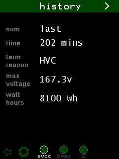
16 Touch the Back Icon in the Toolbar to return to Status. Charging Charge Progress When charging, the Display reverts to a charge progress screen, that shows voltage, amps, and Watt Hours. This screen is purposely dim as it may be on for several hours while charging. Touching the charge progress screen will return to the Status Screen where all operations are available. Charge History Touching the EVCC Icon will show the charge history. Historical information the charge cycles is kept here. Navigation is with the arrows in the title bar. 15
17 16
18 Display Quick Start BMSC Configuration Step 1. Verify the firmware version(s) of each BMSC(s). The BMSC version should be or greater. Step 2. Configure BMS Ids if multiple BMSCs are being used Step 3. Configure cell mapping if non-default cell mapping is used Step 4. Execute the lock command the set the configuration. EVCC Firmware (if the EVCC is being used) Step 5. Verify the EVCC firmware version number by using the serial port. The EVCC version must be or greater. If not, the firmware should be upgraded. Installation Step 6. Mount the Display. Step 7. Connect power. Power up the Display to verify the Startup Screen and touch operation. Step 8. Connect CANH and CANL to the BMS (and EVCC) CAN network. Install the CAN jumper on JP3 if a CAN termination is required at the Display. Power up the BMS, EVCC and Display. Verify that all devices, satellites, and cells can be detected. Step 9. Connect the analog gauge if used. Program the Gauge PWM configuration points. Step 10. Connect the Hall Sensor if used. Configure the.sensor Type and Pack Capacity System Testing Step 11. Spin the motor to verify that the polarity of the Hall Sensor. When drawing current from the pack, the Ammeter should read a negative number. If not, the Hall sensor needs to be turned around. Step 12. If using the EVCC, connect the J1772 charge plug and verify that the Display detects the charge plug, that charging starts Step 13. Verify that the Display can be used to configure EVCC and BMSC parameters Done. 17
19 Warrantee and Support The Thunderstruck return policy is available at The Display is warranted to be free from defects in components and workmanship under normal use and service for a period of 1 year. When failing to perform as specified during the warranty period we will undertake to repair, or at our option, replace this product at no charge to its owner, provided the unit is returned undamaged and shipping prepaid, to Thunderstruck motors. The product is intended for non-commercial use by hobbyists. The warranty does not apply to defects arising from miswiring, abuse or negligence, accidents, opening the enclosure, or reverse engineering. Dilithium Design, LLC shall not be responsible for any incidental or consequential damages. Dilithium Design, LLC reserve the right to make changes or improvements in design or manufacturing without assuming any obligation to change or improve products previously manufactured and / or sold. For general support and warrantee issues, contact the dealer. For errors in this document, or comments about the product, contact djmdilithium@gmail.com Document History Rev 1.0 Feb 22, 2018 Initial Version 18
Integrated Battery Control System LBCS Step-by-Step Setup Guide
 Integrated Battery Control System LBCS Step-by-Step Setup Guide 1. Components of the System 2. Components of the System 3. LBCS Overview 4. Battery Connections 5. Sense Board Installation 6. Sense Board
BMS: Installation Manual v2.x - Documentation
 Page 1 of 7 BMS: Installation Manual v2.x From Documentation This section describes how external peripheral devices are connected and additional functions of the BMS are used. I you have not done so already,
Series 803 LED Product Price Display
 Series 803 LED Product Price Display May 2007 Rev. 1.1 1 Installation and Operation Manual Table of contents 1. Safety.......3 2. Series 803 sign features.......4 2.1 Sign descriptions........4 2.2 Control
Sensacell Troubleshooting Guide
 A ONLY SOME MODULES LIGHT UP B PANEL DOES NOT LIGHT UP Only some modules light up Panel does not light up Check jumpers and power wiring AC Power present at Power Supply input terminals? Check AC Line
FES LCD Display Version 1.1
 FES LCD Display Version 1.1 LZ design d.o.o., Brod 3D, 1370 Logatec, Slovenia tel +386 59 948 898 info@lzdesign.si www.front-electric-sustainer.com Table of Content 1. Important notices... 3 1.1 Limited
MTX-A Temperature Gauge User Manual
 MTX-A Temperature Gauge User Manual 1. Installation... 2 1.1 Gauge Mounting... 2 1.2 Temperature Sensor Mounting... 2 1.2.1 Changing the MTX-A s Gauge Bezel... 2 1.3 Main Gauge Wiring... 3 1.3.1 Single
WR-5e Remote Control
 1. Introduction WR-5e Remote Control The WR-5e is a microprocessor based serial data remote control unit for Ashly NE or NX products. Compatible products currently include Pema amplifiers, ne8800 and ne4800
INSTRUCTION MANUAL. Sensoray Model 720RB/DIN. Relay I/O Board (Rev A) October 12, 2001
 October 12, 2001") INSTRUCTION MANUAL Sensoray Model 720RB/DIN Relay I/O Board (Rev A) October 12, 2001 For Technical Support contact Sensoray Co., Inc. 7313 SW Tech Center Dr., Tigard, Oregon 97223, USA Tel:(503) 684-8005
INSTRUCTION MANUAL Sensoray Model 720RB/DIN Relay I/O Board (Rev A) October 12, 2001 For Technical Support contact Sensoray Co., Inc. 7313 SW Tech Center Dr., Tigard, Oregon 97223, USA Tel:(503) 684-8005
EMS. Electrical Management System. Progressive Industries Incorporated Morrisville, North Carolina
 Progressive Industries Warranty Progressive warrants its products are free from defects in materials and workmanship for a period of three years. This is in lieu of all other warranties, obligations, or
PWRcheck Spring City Drive Waukesha, WI
 PWRcheck www.westmountainradio.com 1020 Spring City Drive Waukesha, WI 53186 262-522-6503 sales@westmountainradio.com 2018 West Mountain Radio, All rights reserved. All trademarks are the property of their
e-ask electronic Access Security Keyless-entry OEM / Dealer / Installer Cargo Lock / Unlock Version Installation & Instructions (UM04 ~ )
") e-ask electronic Access Security Keyless-entry OEM / Dealer / Installer Cargo Lock / Unlock Version Installation & Instructions (UM04 ~ 18990-04) Table of Contents Introduction... 1 e-fob Operation and
e-ask electronic Access Security Keyless-entry OEM / Dealer / Installer Cargo Lock / Unlock Version Installation & Instructions (UM04 ~ 18990-04) Table of Contents Introduction... 1 e-fob Operation and
G540 User Manual. Date Modified: March 5, 2012 Page 1 of 10
 G540 User Manual Date Modified: March 5, 2012 Page 1 of 10 DIMENSIONS PHYSICAL AND ELECTRICAL RATINGS Minimum Maximum Units Supply Voltage 18 50 VDC Motor Current 0 3.5 A Power Dissipation 1 13 W Short
PANDORA HACKER GUIDE
 PANDORA HACKER GUIDE WARNING: Modifying your PCB is not covered by your warranty and any damage caused as a result will be the sole responsibility of the owner to fix or to have fixed at a fee set by the
Display Unit User Manual
 Display Unit User Manual Contents 3 Specifications 3 Display Specifications 3 Absolute Maximum Ratings 3 Characteristics 4 Get started 4 Wiring 5 Application interface 5 Firmware upgrade 8 Settings 9 Display
Universal Keying Adapter 3+
 Universal Keying Adapter 3+ The Universal Keying Adapter Version 3+ kit will allow you to key nearly any transmitter or transceiver with a straight key, electronic keyer, computer serial or parallel port
3000 Series Instructions Read Instructions Carefully!
 Series Instructions Read Instructions Carefully! With buttons Without buttons CURTIS INSTRUMENTS, INC. Kisco Avenue, Mt. Kisco, NY 9 Tel. (9) 9 www.curtisinst.com. Technical Specifications. Electrical
RESIDENTIAL OPERATOR MOTOR CONTROL BOARD REPLACEMENT INSTRUCTIONS
 READ THIS MANUAL CAREFULLY BEFORE BEGINNING INSTALLATION RESIDENTIAL OPERATOR MOTOR CONTROL BOARD REPLACEMENT INSTRUCTIONS PRODUCT FEATURES MODELS: IIA SPRINT 310/510/710 200/250 2000 SERIES 3000 SERIES
e-ask electronic Access Security Keyless-entry RF Keyless-entry entry System TM-Multi Multi Installation Manual FCC ID: TV2EFOB1 (UM21 ~ )
") e-ask electronic Access Security Keyless-entry e-fob RF Keyless-entry entry System TM-Multi Multi Installation Manual FCC ID: TV2EFOB1 (UM21 ~ 22795-01) Table of Contents Introduction... 1 e-fob Operation
e-ask electronic Access Security Keyless-entry e-fob RF Keyless-entry entry System TM-Multi Multi Installation Manual FCC ID: TV2EFOB1 (UM21 ~ 22795-01) Table of Contents Introduction... 1 e-fob Operation
G540 MANUAL MULTIAXIS STEP MOTOR DRIVE
 G540 MANUAL MULTIAXIS STEP MOTOR DRIVE PRODUCT DIMENSIONS PHYSICAL AND ELECTRICAL RATINGS Minimum Maximum Units Supply Voltage 18 50 VDC Motor Current 0 3.5 A Power Dissipation 1 13 W Short Circuit Trip
EV Controls user Guide
 EV Controls user Guide Copyright EV Controls Table of Contents Introduction... EV Controls System Features... General guidelines for installation... Inverter Electrical Pinout Sheet... Drive Inverter Connections...
Ashly WR-5 Remote Control
 1. Introduction Ashly WR-5 Remote Control The WR-5 is a microprocessor based serial data remote control unit for Ashly NE or NX products. Compatible products currently include Pema amplifiers, ne8800 and
Narc Box Owners Manual & Warranty Information
 Narc Box Owners Manual & Warranty Information 800-445-3640 Brandon@NarcBox.com General Description The Narc Box is a portable narcotic security system designed to keep controlled substances locked and
Energy Management System. Operation and Installation Manual
 Energy Management System Operation and Installation Manual AA Portable Power Corp 825 S 19 TH Street, Richmond, CA 94804 www.batteryspace.com Table of Contents 1 Introduction 3 2. Packing List 5 3. Specifications
FES BMS CONTROL MANUAL
 FES BMS CONTROL MANUAL Version 1.26 for BMS control software version 1.31 Suitable for: -FES BATTERY PACK GEN1 (with external BMS-7R) -FES BATTERY PACK GEN2 (with internal BMS-9R) LZ design d.o.o., Brod
G540 4-AXIS DRIVE REV 4: MAY 28, 2010
 Thank you for choosing to purchase the G540 4-Axis Drive System. If you are dissatisfied with it for any reason at all within two weeks of its purchase date, you may return it for a full refund provided
Torque Series LCD Remote Panel Installation/Operation Manual Model: TQ-DSP-12/24
 Torque Series LCD Remote Panel Installation/Operation Manual Model: TQ-DSP-12/24 Section Page Introduction 1 Materials Provided 1 I) Safety Instructions 1 A) Inverter Safety Instructions 1 B) Battery Safety
PMDX-170 Slotted Optical Sensor
 PMDX-170 Slotted Optical Sensor User s Manual Date: 20 May 2009 PMDX Web: http://www.pmdx.com 9704-D Gunston Cove Rd Phone: +1 (703) 372-2975 Lorton, VA 22079-2366 USA FAX: +1 (703) 372-2977 PMDX-170_Manual_10.doc
BrewTroller Phoenix. Owners Manual. Updated - March 14, 2016 BREWTROLLER PHOENIX 1
 BrewTroller Phoenix Owners Manual Updated - March 14, 2016 BREWTROLLER PHOENIX 1 2016 BrewTroller All Rights Reserved. Product warranty or service will not be extended if: (1) the product is repaired,
STATUS Shiloh Road Alpharetta, Georgia (770) FAX (770) Toll Free
 FAX (770) Toll Free") Instruction Manual Model 1582-45L Data Switch September 2010, Rev A REMOTE LOCAL SWITCH STATUS SELECT REMOTE LOCAL LOCAL SELECT CHANNEL SELECT POWER MODEL 1582 SWITCH CROSS TECHNOLOGIES, INC. Data, drawings,
Instruction Manual Model 1582-45L Data Switch September 2010, Rev A REMOTE LOCAL SWITCH STATUS SELECT REMOTE LOCAL LOCAL SELECT CHANNEL SELECT POWER MODEL 1582 SWITCH CROSS TECHNOLOGIES, INC. Data, drawings,
R & D SPECIALTIES SERIES 100 RO CONTROLLER USERS MANUAL. 2004, by R & D Specialties, Inc. All Rights Reserved.
 R & D SPECIALTIES 2004, by R & D Specialties, Inc. All Rights Reserved. No part of this document may be copied or reproduced in any form or by any means without the prior written permission of R & D Specialties.
MSD Advanced RPM Control Module PN 7761
 MSD Advanced RPM Control Module PN 7761 ONLINE PRODUCT REGISTRATION: Register your MSD product online and you ll be entered in our monthly 8.5mm Super Conductor Spark Plug Wire give-away! Registering your
Secured Series: Hub Plus Kit Single Door Controller Package Installation Manual
 Secured Series: Hub Plus Kit Single Door Controller Package Installation Manual This package is designed to simplify the connections to our Secured Series Hub Plus Controller. This will translate into
Instruction Manual for Video OSD Expander Document Version 1.4
 Instruction Manual for Video OSD Expander Document Version 1.4 Thank you for your purchase! This instruction manual will guide you through the installation and operation of your Video OSD Expander (the
AirTest Model CN9000 Series Sensor Controller
 AirTest Model CN9000 Series Sensor Controller AirTest Model CN9000 Series Sensor Controller THEORY OF OPERATION A basic CN9000 configuration consists of Input/Process/Display combination modules, a 3 relay
TR-TEXT_EC. Display module for use with the EMUS BMS from Elektromotus and motor controllers from Curtis Instruments
 TR-TEXT_EC Display module for use with the EMUS BMS from Elektromotus and motor controllers from Curtis Instruments Special features showing data from battery management system and motor controller on
STYLE 3600 SWITCH INTERFACE TRANSMITTER INSTALLATION AND OPERATING INSTRUCTIONS
 STYLE 3600 SWITCH INTERFACE TRANSMITTER INSTALLATION AND OPERATING INSTRUCTIONS The following is intended to provide the basic instructions for installation and operation of the Switch Interface Transmitter
MEGA DIAL PANEL Instructions
 2036 Fillmore Street Davenport, Ia. 52804 563-324-1046 www.racedigitaldelay.com MEGA DIAL PANEL Instructions WARRANTY AND DISCLAIMER DIGITAL DELAY ELECTRONICS INC. WARRANTS THE PRODUCTS IT MANUFACTURES
This document set is applicable to the following part number configurations:
 This document set is applicable to the following part number configurations: Part Number Kit Configuration Instrument Sensors VA200 VA200 - VA200K VA200 1 X A200-HAS Voltmeter and ammeter systems VA200X
Installing Sentor. Hardware Installation
 Remote base site monitoring and control Installing Sentor Hardware Installation Copyright 2000 Sentor Monitoring Systems Pty Ltd Contents: 1 Introduction... 1 2 Sentor GUI... 2 3 ST3000 Controller... 3
RTD Embedded Technologies, Inc.
 CAN SPIDER CAN Bus Hub User s Manual BDM-610040004 Rev. C RTD Embedded Technologies, Inc. AS9100 and ISO 9001 Certified RTD Embedded Technologies, Inc. 103 Innovation Boulevard State College, PA 16803
This document set is applicable to the following part number configurations:
 This document set is applicable to the following part number configurations: Part Number Kit Configuration Instrument Sensors VA200 VA200 - VA200K VA200 1 X A200-HAS Voltmeter and ammeter systems VA200X
MTX-A, Fuel Pressure Gauge PSI
 MTX-A, Fuel Pressure Gauge 0-100 PSI Contents 1 Mounting and Sensor Installation... 2 1.1 Gauge Mounting... 2 1.1.1 Changing the MTX-A s Gauge Bezel... 2 1.2 Fuel Pressure Sensor... 2 2 Wiring... 3 2.1
DVI KVM. Extra Long Range Extender Over One CAT5. User Manual EXT-DVIKVM-ELR. Release A8
 DVI KVM Extra Long Range Extender Over One CAT5 EXT-DVIKVM-ELR User Manual Release A8 Important Safety Instructions 1 Read these instructions 2 Keep these instructions 3 Heed all warnings 4 Follow all
AWP-24-3 Wave Height Gauge User's Guide
 AWP-24-3 Wave Height Gauge User's Guide Issue: 1.5 Status: Released 18-Dec-2014 Prepared by Akamina Technologies Inc. Akamina Technologies Inc. 91 Norice St.,Ottawa,Ontario K2G 2X9, CANADA TEL: +1 613
Torque Meter. Instruction Manual
 Torque Meter 840062 Instruction Manual CONTENTS I. Introduction... 4 II. Meter Description... 4 III. Operating Instructions 1. Measuring Procedures... 5 2. Automatic Shut Off... 6 3. Battery Replacement...
TB-100 ControLynx Terminal Block
 TB-100 ControLynx Terminal Block TECHNICAL MANUAL Version 1.3 September 2006 Copyright This technical manual and the equipment, firmware and software described herein are copyrighted by INTENT DIGITAL
Orion Jr. Purchasing Guide Rev. 1.2
 www.orionbms.com Orion Jr. Purchasing Guide Rev. 1.2 The Orion Jr. BMS is a low cost battery management system designed to manage low voltage lithium ion battery packs up to 48V nominal. The Orion Jr.
DCM Digital Control Modules
 DCM Digital Control Modules TECHNICAL MANUAL Version 1.2 November 2011 Safety Precautions Caution Read Instructions: Read and understand all safety and operating instructions before using the equipment.
VR2 R-NET LED R-NET LCD. Controller System Operation
 VR2 R-NET LED R-NET LCD Controller System Operation 1.VR2 Controller Operation 1.1 Controls/JSM 1.2 Button/Indicator 1.3 Control System Status indication 1.4 Module Wiring 1.5 VR2 Locking / Unlocking The
Wasp Embedded Controller
 Wasp Embedded Controller Wasp16/32/64 Hardware Reference Guide PCB Rev 1.0 WASP16 WASP32 WASP64 MC433 Hardware Reference Guide Manual Revision 0.85 Table of Contents Warranty Statement...2 1.0 Introduction....4
232iLM Keypad Installation and Programming Instructions
 232iLM Keypad Installation and Programming Instructions Note: This product is designed to be installed and serviced by security and lock industry professionals. Specifications Case Dimensions: 6 1 / 2
Pridgen Vermeer Robotics ATmega128 Revision 0
 Features: 6x 8-bit I/O Ports 4x A/D Inputs 6x PWM Headers 2x RS 232 Terminals Power Bus LCD Header (4-bit mode) Smart Power Connecter Power Switch Header Power LED Debug LED Note: Some pins have multiple
I/O Expansion Box Installation & Operator s Instruction Manual
 I/O Expansion Box Installation & Operator s Instruction Manual May 2004 CTB Inc. Warranty I/O Expansion Box CTB Inc. Warranty CTB Inc. warrants each new Chore-Tronics product manufactured by it to be free
INSTALLATION INSTRUCTIONS 5" SINGLE CHANNEL ULTIMATE TACH
 Instr. No. 2650-887C INSTALLATION INSTRUCTIONS 5" SINGLE CHANNEL ULTIMATE TACH MODEL 6871, 6872, 6873, 6874, 6875, 6877 IMPORTANT WEAR SAFETY GLASSES 5 4 6 COPYRIGHT PATENT PENDING 3 7 8 PLAYBACK 9 2 0
poly-planar Marine Audio System
 ME-52 Expansion Amplifier 1 ME-52 Expansion Amplifier Introduction: The ME-52 is a 2 channel audio amplifier capable of delivering up to 25W RMS per channel. It s compact, water resistant design allows
Table of Contents 1 ABOUT THIS GUIDE CONTACT INFORMATION ANTENNA INSTALLATION... 4
 Table of Contents 1 ABOUT THIS GUIDE... 3 1.1 CONTACT INFORMATION... 3 2 ANTENNA INSTALLATION... 4 2.1 GENERAL INFORMATION... 4 2.2 SPECIFIC MOUNTING EXAMPLES... 5 2.3 CONNECTOR MOISTURE PROTECTION...
LPG STM 94442A User s Manual
 1 LPG STM 94442A User s Manual This Manual belongs to: Company: 3 Table of Contents Features....... 4 Hardware Installation...5 Monitor Mounting Dimensions.....7 Monitor Specifications...8 Sender Specifications.....9
Brushless DC Motor Controller Specification Assembly 025A0053
 Brushless DC Motor Controller Specification Assembly 025A0053 600A0053 Rev. 2 July 28, 2004 025A0053 Brushless DC Motor Controller Data Sheet Page 1 Revision History Date Rev Description By 5/15/04 1 Initial
Digital Lighting Systems, Inc.
 , Inc. DMX512 Multi channel logic controller DMX512 X Y AUTO MAN. ON OFF PATTERN SPEED USER MANUAL Matrix User's Manual - Page 1 W MODEL Maximum Outside Dimensions WIDTH HEIGHT DEPTH 2.40 061 mm 4.600"
TECHNICAL DATASHEET #TDAX050000K CAN
 This cost-effective, compact and robust CAN display shows machine, engine and transmission operating parameters and service codes. Enhanced operating information made available to a vehicle operator improves
1411 S. Roselle Rd. Schaumburg, IL Phone (847) Fax (847)
 Fax (847)") The Touch Screen Control System consists of two components, the Touch Screen (TS) and the Switch Panel Module(SPM). The PowerQuest system can control the switching of 8 circuits. 6 circuits are predefined
The Touch Screen Control System consists of two components, the Touch Screen (TS) and the Switch Panel Module(SPM). The PowerQuest system can control the switching of 8 circuits. 6 circuits are predefined
Digital Lighting Systems, Inc. PD216. Two Channel Dimmer and Switch Packs PROTOCOL USER'S MANUAL. PD216-UM Rev. E - 02/03
 Digital Lighting Systems, Inc. PD26 Two Channel Dimmer and Switch Packs PROTOCOL PD26 S2 S USER'S MANUAL PD26-UM Rev. E - 02/03 Digital Lighting Systems PD26 User's Manual - Page GENERAL DESCRIPTION The
Global Water Instrumentation, Inc.
 Instrumentation, Inc. 11390 Amalgam Way Gold River, CA 95670 T: 800-876-1172 Int l: (916) 638-3429, F: (916) 638-3270 Display: EZ100 11/12/04-1 - Congratulations on your purchase of the EZ100 Display.
ISAscale High Current Sensor Module For Electric Vehicles
 ISAscale High Current Sensor Module For Electric Vehicles 1 INTRODUCTION This User Manual describes use and operation of the ISAscale IVT-Modular high current sensor module for Electric Vehicles. The IVT
ACCURATE ELECTRONICS INC PO BOX SW HALL BLVD BEAVERTON OR USA FAX
 Page 1 of 6 Model 104445A January 2014 ACCURATE ELECTRONICS INC PO BOX 1654 97075-1654 8687 SW HALL BLVD 97008 BEAVERTON OR USA 503.641.0118 FAX 503.646.3903 WWW.ACCURATE.ORG Practice Section 104445A Rev
Two Module Development Kit Installation and User Instructions For Model No. ED-GV15/30
 Two Module Development Kit Installation and User Instructions For Model No. ED-GV15/30 This Kit is designed to be used as a development platform; performance, regulatory or safety testing for commercial
DVI ELR Extender over one CAT5
 DVI ELR Extender over one CAT5 EXT-DVI-1CAT5-ELR User Manual Important Safety Instructions 1 Read these instructions 2 Keep these instructions 3 Heed all warnings 4 Follow all instructions 5 Do not use
Figure 18: Basic input port drawing.
 Appendix A Hardware Inputs The mx_ctlr.0 board has several different types of inputs and outputs allowing for a wide range of functions and actions. The inputs for the board can be broken into three basic
Instruction Manual. Balanced Audio Upgrade Installation. iport IW-21/IW-22 Upgrade Kits. Balanced Audio Upgrade Kit. (iport IW-21)
") Introduction The iport IW Balanced Audio, Balanced Video, and RS-232 Upgrade Kits add functionality and capability to iport IW-21 and IW-22 models. Balanced Audio Upgrade Kit For use with iport IW-21 models.
Introduction The iport IW Balanced Audio, Balanced Video, and RS-232 Upgrade Kits add functionality and capability to iport IW-21 and IW-22 models. Balanced Audio Upgrade Kit For use with iport IW-21 models.
Owner s Manual. TSD-DCPDV DC Power Distribution with Fixed & Variable Outputs. TSD-DCPDV DC Power Distribution. AtlasIED.com
 Owner s Manual with Fixed & Variable Outputs 1 AtlasIED.com Owner s Manual Description The AtlasIED Variable Block is designed to reduce cost and wiring clutter in installations where multiple DC power
CONNECTOR AND RECEPTACLE WIRE/CABLE ASSEMBLY INSTRUCTIONS
 CONNECTOR AND RECEPTACLE WIRE/CABLE ASSEMBLY INSTRUCTIONS Throughout this manual, look for this symbol. It means BE ALERT YOUR SAFETY IS INVOLVED. If you do not follow these safety instructions, personal
DVI Extra Long Range Extender
 DVI Extra Long Range Extender EXT-DVI-ELR User Manual www.gefen.com ASKING FOR ASSISTANCE Technical Support: Telephone (818) 772-9100 (800) 545-6900 Fax (818) 772-9120 Technical Support Hours: 8:00 AM
PWRguard PLUS Spring City Drive Waukesha, WI
 PWRguard PLUS www.westmountainradio.com 1020 Spring City Drive Waukesha, WI 53186 262-522-6503 sales@westmountainradio.com 2016, All rights reserved. All trademarks are the property of their respective
EP/2 Installation Instructions
 1 2 3 4 7 ENTER 0 5 6 8 9 CLEAR + - LOGIC ONE EP/2 EP/2 Installation Instructions DOC. #569011000 A 7/30/04 PRINTED IN U.S.A. Regulatory Compliance Safety This device has been tested and found to be in
CAT5-1600A Extender. EXT-CAT5-1600A User Manual.
 CAT5-1600A Extender EXT-CAT5-1600A User Manual www.gefen.com ASKING FOR ASSISTANCE Technical Support: Telephone (818) 772-9100 (800) 545-6900 Fax (818) 772-9120 Technical Support Hours: 8:00 AM to 5:00
12.3 Pro Dash Quick Start Guide
 12.3 Pro Dash Quick Start Guide 553-111 CONTENTS: Package Contents... 3 Mounting... 3 Connections... 4 Main Connector... 4 CAN Extension Harness... 6 USB... 7 GPS Antenna... 7 Cleaning... 7 Touchscreen
Rover 5. Explorer kit
 Rover 5 Explorer kit The explorer kit provides the perfect interface between your Rover 5 chassis and your micro-controller with all the hardware you need so you can start programming right away. PCB Features:
TDM-170 TIMER DISPLAY
 TDM-170 TIMER DISPLAY TECHNICAL MANUAL Version 1.1 August 2016 TDM-170 Timer Display Technical Manual Safety Precautions Caution Read Instructions: Read and understand all safety and operating instructions
BTU-4D/BTU-4D-I Digital Temperature Unit & Sensors. Installation and Operation Manual
 BTU-4D/BTU-4D-I Digital Temperature Unit & Sensors Installation and Operation Manual BTU-4D/BTU-4D-I Installation and Operation Manual Rev E Table of Contents Introduction... 1 TEMP OUTDOOR Sensor... 1
AWP-24 Wave Height Gauge User's Guide
 AWP-24 Wave Height Gauge User's Guide Issue: 2.3 5-October-2012 Prepared by Akamina Technologies Inc. Akamina Technologies Inc. 91 Norice St.,Ottawa,Ontario K2G 29, CANADA TEL: +1 613 720 7555 FA: +1 613
EnCell Battery Cell Monitor
 EnCell Battery Cell Monitor Instruction Manual Model RCM15S12 NERC Compliant YO R U H T PA TO Z O R E W O D N M I T E enchargepowersystems.com sales@enchargepowersystems.com (888) 407.5040 Contents 1 Warnings,
Sierra 80 Volt Brushless DC Motor Controller Product Specification
 Sierra 80 Volt Brushless DC Motor Controller Product Specification Assembly 025F0135 600A0588 Rev. B January 29, 2010 025F0135 Brushless DC Motor Controller Page 1 Revision History ECN # Date Rev Description
DVI ELR Extender over one CAT5
 DVI ELR Extender over one CAT5 EXT-DVI-1CAT5-ELR User Manual Release A3 Important Safety Instructions 1. Read these instructions. 2. Keep these instructions. 3. Heed all warnings. 4. Follow all instructions.
212iL Rev. 1.1
 212iL 1 International Electronics, Inc. 427 Turnpike Street Canton, Massachusetts 02021 212iL (illuminated Luxury) Keypad Single Unit Keypad- Control Installation Manual Features: 120 User Capability Illuminated
AB0602D ARCHITECTURAL BALLAST DRIVER. Version Date 06/25/2012
 AB0602D ARCHITECTURAL BALLAST DRIVER Version 0.10 Date 06/25/2012 Page 2 of 10 DESCRIPTION AND FEATURES The AB-0602D is a 6 circuit, 2400 Watts per circuit ballast driver intended for dimmable fluorescent
MT-150. RENOGY 150A Peak High Precision Watt Meter and Power Analyzer E. Philadelphia St., Ontario CA Version: 1.
 MT-150 RENOGY 150A Peak High Precision Watt Meter and Power Analyzer 0 2775 E. Philadelphia St., Ontario CA 91761 1-800-330-8678 Version: 1.1 Important Safety Instructions Please save these instructions.
FLAP indicator. Installation manual Version 1.10
 FLAP indicator Installation manual Version 1.10 LXNAV d.o.o. Kidričeva 24, 3000 Celje, Slovenia tel +386 592 33 400 fax +386 599 33 522 info@lxnav.com www.lxnav.com 1 Important Notices... 3 1.1 Limited
V TU24 V350-J-TU24
 Vision PLC+HMI V350-35-TU24 V350-J-TU24 Installation Guide 12 Digital Inputs, including 2 Analog, 2 PT100/TC,1 HSC/Shaft-encoder input 12 Transistor Outputs General Description All of the controllers covered
Torque Meter. Instruction Manual
 Torque Meter 840062 Instruction Manual Torque Meter - 840062 Copyright 2013 by Sper Scientific ALL RIGHTS RESERVED Printed in the USA The contents of this manual may not be reproduced or transmitted in
Kramer Electronics, Ltd. USER MANUAL. Model: RC-52N. Room Controller
 Kramer Electronics, Ltd. USER MANUAL Model: RC-52N Room Controller Contents Contents 1 Introduction 1 2 Getting Started 1 3 Overview 2 4 Your RC-52N 3 4.1 The RC-52N Front Panel 3 4.2 The RC-52N Rear Panel
Follow these simple installation instructions to get professional results.
 Follow these simple installation instructions to get professional results. LED Real -Time Display Wireless Remote Control System. Dash Mount Charger / Cradle for Wireless Remote. 4 Normal Modes - 3 Million
SECURE/NONSECURE LED SIGN USER MANUAL
 SECURE/NONSECURE LED SIGN USER MANUAL December 2012 Wall Mount Part Number: 51-01198 1U Rack Mount Part Number: 51-01196 500 Business Center Drive, Pittsburgh, PA 15205 Phone: (412) 494-2800, Fax: (412)
This revision of the manual is dated June, All modifications from previous versions are listed in the appendix.
 , Incorporated 16525 East Laser Drive Fountain Hills, AZ 85268 480-837-5200 FAX 837-5300 info@embeddedx86.com http://www.embeddedx86.com/ This revision of the manual is dated June, 01 2009 All modifications
EMS Electrical Management System
 EMS Electrical Management System Complete Installation/Operating & Warranty Guide EMS-HW50C Rated at 240 Volts/50 Amps Manufactured & Warranted by Progressive Industries Sold & Serviced by VIP Enterprises
TDM-150 TIMER DISPLAY
 TDM-150 TIMER DISPLAY TECHNICAL MANUAL Covers TDM-150D, TDM-150F Version 1.1 August 2016 Safety Precautions Caution Read Instructions: Read and understand all safety and operating instructions before using
Contents 1 Warnings, Cautions, and Notes Description Features... 1
 EnCell Contents 1 Warnings, Cautions, and Notes... 1 2 Description... 1 3 Features... 1 3.1 STANDARD FEATURES... 1 3.2 FRONT PANEL FEATURES... 2 3.2.1 Display... 2 3.2.2 OK LED... 2 3.2.3 FAULT LED...
INSTRUCTION MANUAL A START-UP AND SHUT DOWN LOAD SEQUENCER AND AUTOMATIC LOAD SHEDDING SYSTEM WITH INTEGRAL RELAYS FOR 8 LOADS MODEL #091-60A
 FILE: 09-60A.PMD DATE: 07-30-09 REV. B INSTRUCTI MANUAL LOAD MANAGER MARK II A START-UP AND SHUT DOWN LOAD SEQUENCER AND AUTOMATIC LOAD SHEDDING SYSTEM WITH INTEGRAL RELAYS FOR 8 LOADS MODEL #09-60A INPUT:
OPENUPS 6-34V Intelligent Uninterruptible Power Supply
 OPENUPS 6-34V Intelligent Uninterruptible Power Supply Installation Guide Version 1.0f Before you start Please take a moment and read this manual before you install the OPENUPS. Often times, rushing into
poly-planar Marine Audio Systems
 ME60BT Bluetooth Amplifier 1 Introduction: The ME60BT is a four channel, 120 Watts RMS Bluetooth wireless audio amplifier, capable of delivering up to 30W RMS per channel. It has a compact, water resistant
AirPro Surveyor 2 Manual
 AirPro Surveyor 2 Manual AirPro Surveyor Specifications Table of Contents Size 3/8 x 7 1/2 x 4 3/8 Weight 4.6 lbs. 2094 g Dynamic Range 1-1000 ml/min. total flow/constant flow Flow Capacity (8 Hrs.) 1000