Computer-Aided Digital System Design VHDL
|
|
|
- Raymond McDowell
- 5 years ago
- Views:
Transcription

1 بس م اهلل الر حم ن الر حی م Iran University of Science and Technology Department of Computer Engineering Computer-Aided Digital System Design VHDL Ramin Rajaei
2 Modeling Styles From the level of abstraction systems can be described in there types: 1. Behavioral 2. Dataflow 3. Structural VHDL Hierarchy 2
3 Modeling Styles Sequential vs. Concurrent Statements VHDL provides two different types of execution: sequential and concurrent. Different types of execution are useful for modeling of real hardware. Supports various levels of abstraction. Sequential statements view hardware from a programmer approach. Concurrent statements are order-independent and asynchronous. 3
4 Examples for Architecture Declaration Sequential (behavioral) Style Data flow Style Structural Style 4
5 Behavioral We can describe a system in terms of processing it performs on its input signals and the type of output it signals it produces. Example : LIBRARY ieee; USE ieee.std_logic_1164.all; ENTITY eq_comp4 is PORT( a,b : in std_logic_vector(3 downto 0); equals : out std_logic); END ; ARCHITECTURE behvioral OF eq_comp4 IS BEGIN comp: PROCESS (a,b) BEGIN IF (a=b) then equals <= '1'; Else equals <= '0'; END IF; END PROCESS comp; END behvioral; 5
6 Data Flow Dataflow architecture specifies how data will be transferred from signal to signal and input to input without the sequential statements. Primary difference is that behavioral uses processes while dataflow does not. The other main difference between dataflow and behavioral architectures is that the body of the process statement contains only sequential statements. Example: library ieee; use ieee.std_logic_1164.all; entity eq_comp4 is port ( end eq_comp4; a,b : in std_logic_vector(3 downto 0); equals : out std_logic); architecture bool of eq_comp4 is begin equals <= not (a(0) xor b(0)) and not (a(1) xor b(1)) and not (a(2) xor b(2)) and not (a(3) xor b(3)); end bool; 6
; What circuit this architecture means?")
7 Structural One way to describe a system is to describe component chips and the interconnections assuming that the user is familiar with it. This kind of definition is the structural definition. Example: library ieee; use ieee.std_logic_1164.all; entity full_adder is port( a,b,ci : in std_logic; sum,co : out std_logic); What circuit this architecture means? end full_adder; architecture bool of full_adder is signal s1,s2,s3 : std_ulogic; begin u0: s1 <= (a xor b); u1: s2 <= (ci and s1); u2: s3 <= (a and b); u3: sum <= (s1 xor ci); u4 : co <= (s2 or s3); end bool; 7
8 Standard VHDL operators Logical - defined for type BIT AND, NAND OR, NOR XOR, XNOR NOT Relational - defined for types BIT, BIT_VECTOR, INTEGER = (equal to) =/ (not equal to) < (less than) = < (less than or equal to) > (greater than) = > (greater than or equal to) 8
9 Standard VHDL operators Unary Arithmetic - defined for type INTEGER - (arithmetic negate) Arithmetic - defined for type INTEGER + (addition) - (subtraction) Concatenation - defined for types STRING, BIT, BIT_VECTOR & 9
10 Concurrency 10
11 Sequential Style Syntax Assignments are executed sequentially inside processes. 11

12 A D-Flip Flop D CLEAR CLK DFF Q 12
13 Sequential Statements {Signal, Variable} assignments Flow control if <condition> then <statments> [elsif <condition> then <statments>] else <statements> end if; for <range> loop <statments> end loop; while <condition> loop <statments> end loop; case <condition> is when <value> => <statements>; when <value> => <statements>; when others => <statements>; Wait on <signal> until <expression> for <time>; 13
14 Data Objects There are three types of data objects: Signals Can be considered as wires in a schematic. Can have current value and future values. Variables and Constants Used to model the behavior of a circuit. Used in processes, procedures and functions. 14
15 Signal Declaration and Assignment Signals are used for communication between components. Signals are declared outside the process. Signals can be seen as real, physical signals. Some delay must be incurred in a signal assignment. A key difference between variables and signals is the assignment delay. 15
16 Variable Declaration and Assignment Variables are used for local storage of data. Variables are generally not available to multiple components or processes. All variable assignments take place immediately. Variables are more convenient than signals for the storage of (temporary) data. 16
17 Constant Declaration A constant can have a single value of a given type. A constant s value cannot be changed during the simulation. Constants declared at the start of an architecture can be used anywhere in the architecture. Constants declared in a process can only be used inside the specific process. CONSTANT constant_name : type_name [ : = value]; CONSTANT rise_fall_time : TIME : = 2 ns; CONSTANT data_bus : INTEGER : = 16; 17


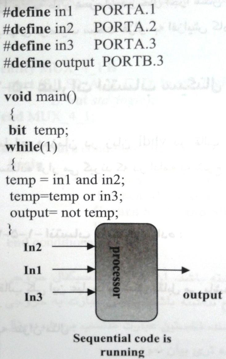
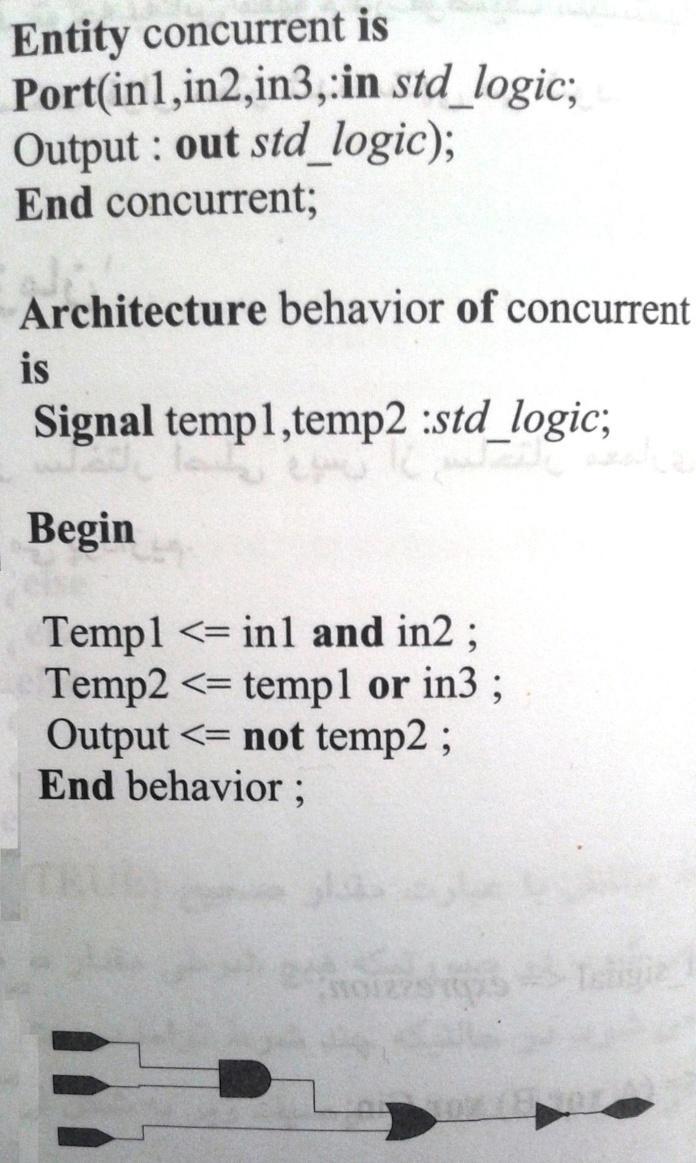
18 Signals vs. Variables Variable is used when you want to create a serialized code, unlike the normal parallel code. A variable, can exist only inside a process, and the assignment of values is not parallel. For example, the fallowing code: 18
19 Signals vs. Variables entity sig_var is port (In1: in std_logic; In2: in std_logic; out1: out std_logic); end sig_var; architecture Behavioral of sig_var is begin process(in1, In2) variable a, b: std_logic; begin a := In1 and In2; b := a and In2; out1 <= b and In2; end process; end Behavioral; 19
20 Signals vs. Variables entity sig_var is port (In1: in std_logic; In2: in std_logic; out1: out std_logic); end sig_var; architecture Behavioral of sig_var is signal a, b: std_logic; begin process(in1, In2) begin a <= In1 and In2; b <= a and In2; out1 <= b and In2; end process; end Behavioral; 20
; end sig_var; architecture")
21 Signals vs. Variables entity sig_var is port (In1: in std_logic; In2: in std_logic; out1: out std_logic); end sig_var; architecture Behavioral of sig_var is signal a, b: std_logic; begin a <= In1 and In2; b <= a and In2; out1 <= b and In2; end Behavioral; 21
22 Signal vs Variable: synthesis entity sig_var is port (clk: in std_logic; Din: in std_logic_vector (3 downto 0); out1: out std_logic_vector (3 downto 0)); end sig_var; architecture Behavioral of sig_var is signal a, b: std_logic_vector (3 downto 0); begin process(clk) begin if (rising_edge(clk)) then a <= Din; b <= a; end if; end process; out1 <= b; end Behavioral; 22
23 Signal vs Variable: synthesis entity sig_var is port (clk: in std_logic; Din: in std_logic_vector (3 downto 0); out1: out std_logic_vector (3 downto 0)); end sig_var; architecture Behavioral of sig_var is signal a, b: std_logic_vector (3 downto 0); begin process(clk) begin if (rising_edge(clk)) then a <= Din; b <= a; out1 <= b; end if; end process; end Behavioral; 23
24 IF vs. CASE statement Syntax 24
25 FOR vs. WHILE statement Syntax For is considered to be a combinational circuit by some synthesis tools. Thus, it cannot have a wait statement to be synthesized. While is considered to be an FSM by some synthesis tools. Thus, it needs a wait statement to be synthesized. 25
26 WAIT statement Syntax The wait statement causes the suspension of a process statement or a procedure. wait [sensitivity_clause] [condition_clause] [timeout_clause]; Sensitivity_clause ::= on signal_name wait on CLOCK; Condition_clause ::= until boolean_expression wait until Clock = 1 ; Timeout_clause ::= for time_expression wait for 150 ns; wait until clk event and clk= 1 ; wait until rising_edge(clk); 26

27 Sensitivity-lists vs Wait-on - statement 27
; end process_example; architecture")
 then out2 <= D2; end if; end process; end")
28 Example entity process_example is Port ( clk : in STD_LOGIC; D1, D2: in std_logic; reset: in std_logic; out1 : out STD_LOGIC; out2 : out STD_LOGIC); end process_example; architecture Behavioral of process_example is begin process begin if reset = '1' then out1 <= '0'; else out1 <= D1; end if; if rising_edge(clk) then out2 <= D2; end if; end process; end Behavioral; 28
29 Example (cont.) entity process_example is Port ( clk : in STD_LOGIC; D1, D2: in std_logic; reset: in std_logic; out1 : out STD_LOGIC; out2 : out STD_LOGIC); end process_example; architecture Behavioral of process_example is begin process begin wait until rising_edge (clk); if reset = '1' then out1 <= '0'; else out1 <= D1; end if; out2 <= D2; end process; end Behavioral; 29
 Error message: line 36: Bad condition in wait")
30 Example (cont.) Error message: line 36: Bad condition in wait statement, or only one clock per process. 30
31 Concurrent Process Equivalents All concurrent statements correspond to a process equivalent. U0: q <= a xor b after 5 ns; is short hand notation for U0: process begin q <= a xor b after 5 ns; wait on a, b; end process; 31
32 Structural Statements The component instantiation is one of the building blocks of structural descriptions. The component instantiation process requires component declarations and component instantiation statements. Component instantiation declares the interface of the components used in the architecture. At instantiation, only the interface is visible. The internals of the component are hidden. 32
33 Component Declaration and Instantiation The component declaration declares the interface of the component to the architecture. Necessary if the component interface is not declared elsewhere (package, library). The instantiation statement maps the interface of the component to other objects in the architecture. 33
34 Component Instantiation Syntax The instantiation has 3 key parts Name Component type Port map 34
35 Examples: architecture first of add4 is begin s <= a + b; -- works with std_logic_vector or integer end; architecture second of add4 is signal c: std_logic_vector(2 downto 0); begin s(0) <= a(0) XOR b(0); c(0) <= a(0) AND b(0); s(1) <= a(1) XOR (b(1) XOR c(0)); c(1) <=.. end add4; 35
36 Example: n-bit Comparator library ieee; use ieee.std_logic_1164.all entity Comparator is port( A: in std_logic_vector(1 downto 0); B: in std_logic_vector(1 downto 0); less: out std_logic; equal: out std_logic; greater: out std_logic ); end Comparator; architecture behv of Comparator is Begin process(a,b) Begin if (A<B) then less <= '1'; equal <= '0'; greater <= '0'; elsif (A=B) then less <= '0'; equal <= '1'; greater <= '0'; else less <= '0'; equal <= '0'; greater <= '1'; end if; end process; end behv; 36
37 More Examples for Review 37
38 Example: 38
39 Synthesis Result 39
40 Example: entity reg4 is port (clk, clr : in bit; d : in bit_vector(0 to 3); q : out bit_vector(0 to 3); end entity reg4; architecture struct of reg4 is component flipflop is generic (Tprop, Tsetup, Thold : delay_length); port ( clk, clr, d : in bit; q : out bit); end component flipflop; begin bit0: component flipflop generic map ( Tprop => 2 ns, Tsetup => 2ns, Thold => 1ns) port map ( clk => clk, clr => clr, d => d(0), q => q(0) ); bit1: component flipflop generic map ( Tprop => 2 ns, Tsetup => 2ns, Thold => 1ns) port map ( clk => clk, clr => clr, d => d(1), q => q(1) ); bit2: component flipflop generic map ( Tprop => 2 ns, Tsetup => 2ns, Thold => 1ns) port map ( clk => clk, clr => clr, d => d(2), q => q(2) ); bit3: component flipflop generic map ( Tprop => 2 ns, Tsetup => 2ns, Thold => 1ns) port map ( clk => clk, clr => clr, d => d(3), q => q(3) ); end architecture struct; 40
41 Example: Array of AND-gates 41

42 Next Sessions: In Lec-5, we will have a tutorial for Modelsim. And also Exercise 2 42
EEL 4783: Hardware/Software Co-design with FPGAs
 EEL 4783: Hardware/Software Co-design with FPGAs Lecture 9: Short Introduction to VHDL* Prof. Mingjie Lin * Beased on notes of Turfts lecture 1 What does HDL stand for? HDL is short for Hardware Description
Hardware Description Language VHDL (1) Introduction
 Introduction") Hardware Description Language VHDL (1) Introduction Digital Radiation Measurement and Spectroscopy NE/RHP 537 Introduction Hardware description language (HDL) Intended to describe circuits textually, for
Hardware Description Language VHDL (1) Introduction Digital Radiation Measurement and Spectroscopy NE/RHP 537 Introduction Hardware description language (HDL) Intended to describe circuits textually, for
EECE-4740/5740 Advanced VHDL and FPGA Design. Lecture 3 Concurrent and sequential statements
 EECE-4740/5740 Advanced VHDL and FPGA Design Lecture 3 Concurrent and sequential statements Cristinel Ababei Marquette University Department of Electrical and Computer Engineering Overview Components hierarchy
Modeling Complex Behavior
 Modeling Complex Behavior Sudhakar Yalamanchili, Georgia Institute of Technology, 2006 (1) Outline Abstraction and the Process Statement Concurrent processes and CSAs Process event behavior and signals
Abi Farsoni, Department of Nuclear Engineering and Radiation Health Physics, Oregon State University
 Hardware description language (HDL) Intended to describe circuits textually, for a computer to read Evolved starting in the 1970s and 1980s Popular languages today include: VHDL Defined in 1980s by U.S.
Basic Language Concepts
 Basic Language Concepts Sudhakar Yalamanchili, Georgia Institute of Technology ECE 4170 (1) Describing Design Entities a sum b carry Primary programming abstraction is a design entity Register, logic block,
VHDL And Synthesis Review
 VHDL And Synthesis Review VHDL In Detail Things that we will look at: Port and Types Arithmetic Operators Design styles for Synthesis VHDL Ports Four Different Types of Ports in: signal values are read-only
IT T35 Digital system desigm y - ii /s - iii
 UNIT - V Introduction to Verilog Hardware Description Language Introduction HDL for combinational circuits Sequential circuits Registers and counters HDL description for binary multiplier. 5.1 INTRODUCTION
In our case Dr. Johnson is setting the best practices
 VHDL Best Practices Best Practices??? Best practices are often defined by company, toolset or device In our case Dr. Johnson is setting the best practices These rules are for Class/Lab purposes. Industry
Hardware Description Languages. Modeling Complex Systems
 Hardware Description Languages Modeling Complex Systems 1 Outline (Raising the Abstraction Level) The Process Statement if-then, if-then-else, if-then-elsif, case, while, for Sensitivity list Signals vs.
VHDL. ELEC 418 Advanced Digital Systems Dr. Ron Hayne. Images Courtesy of Cengage Learning
 VHDL ELEC 418 Advanced Digital Systems Dr. Ron Hayne Images Courtesy of Cengage Learning Design Flow 418_02 2 VHDL Modules 418_02 3 VHDL Libraries library IEEE; use IEEE.std_logic_1164.all; std_logic Single-bit
Lecture 7. Standard ICs FPGA (Field Programmable Gate Array) VHDL (Very-high-speed integrated circuits. Hardware Description Language)
 VHDL (Very-high-speed integrated circuits. Hardware Description Language)") Standard ICs FPGA (Field Programmable Gate Array) VHDL (Very-high-speed integrated circuits Hardware Description Language) 1 Standard ICs PLD: Programmable Logic Device CPLD: Complex PLD FPGA: Field Programmable
Standard ICs FPGA (Field Programmable Gate Array) VHDL (Very-high-speed integrated circuits Hardware Description Language) 1 Standard ICs PLD: Programmable Logic Device CPLD: Complex PLD FPGA: Field Programmable
2/14/2016. Hardware Synthesis. Midia Reshadi. CE Department. Entities, Architectures, and Coding.
 Hardware Synthesis MidiaReshadi CE Department Science and research branch of Islamic Azad University Email: ce.srbiau@gmail.com Midia Reshadi 1 Chapter 2 Entities, Architectures, and Coding Styles Midia
Review of Digital Design with VHDL
 Review of Digital Design with VHDL Digital World Digital world is a world of 0 and 1 Each binary digit is called a bit Eight consecutive bits are called a byte Hexadecimal (base 16) representation for
VHDL for FPGA Design. by : Mohamed Samy
 VHDL for FPGA Design by : Mohamed Samy VHDL Vhdl is Case insensitive myvar = myvar = MYVAR IF = if = if Comments start with -- Comments can exist anywhere in the line Semi colon indicates the end of statements
Introduction to VHDL #1
 ECE 3220 Digital Design with VHDL Introduction to VHDL #1 Lecture 3 Introduction to VHDL The two Hardware Description Languages that are most often used in industry are: n VHDL n Verilog you will learn
Sequential Statement
 Sequential Statement Sequential Logic Output depends not only on current input values but also on previous input values. Are building blocks of; Counters Shift registers Memories Flip flops are basic sequential
ECE 448 Lecture 4. Sequential-Circuit Building Blocks. Mixing Description Styles
 ECE 448 Lecture 4 Sequential-Circuit Building Blocks Mixing Description Styles George Mason University Reading Required P. Chu, FPGA Prototyping by VHDL Examples Chapter 4, Regular Sequential Circuit Recommended
C-Based Hardware Design
 LECTURE 6 In this lecture we will introduce: The VHDL Language and its benefits. The VHDL entity Concurrent and Sequential constructs Structural design. Hierarchy Packages Various architectures Examples
CSE 260 Introduction to Digital Logic and Computer Design. Exam 1. Your name 2/13/2014
 CSE 260 Introduction to Digital Logic and Computer Design Jonathan Turner Exam 1 Your name 2/13/2014 1. (10 points) Draw a logic diagram that implements the expression A(B+C)(C +D)(B+D ) directly (do not
Lecture 4: Modeling in VHDL (Continued ) EE 3610 Digital Systems
 EE 3610 Digital Systems") EE 3610: Digital Systems 1 Lecture 4: Modeling in VHDL (Continued ) Sequential Statements Use Process process (sensitivity list) variable/constant declarations Sequential Statements end process; 2 Sequential
EE 3610: Digital Systems 1 Lecture 4: Modeling in VHDL (Continued ) Sequential Statements Use Process process (sensitivity list) variable/constant declarations Sequential Statements end process; 2 Sequential
A bird s eye view on VHDL!
 Advanced Topics on Heterogeneous System Architectures A bird s eye view on VHDL Politecnico di Milano Conference Room, Bld 20 19 November, 2015 Antonio R. Miele Marco D. Santambrogio Politecnico di Milano
Digital Systems Design
 Digital Systems Design Review of Combinatorial Circuit Building Blocks: VHDL for Combinational Circuits Dr. D. J. Jackson Lecture 2-1 Introduction to VHDL Designer writes a logic circuit description in
Lecture 3: Modeling in VHDL. EE 3610 Digital Systems
 EE 3610: Digital Systems 1 Lecture 3: Modeling in VHDL VHDL: Overview 2 VHDL VHSIC Hardware Description Language VHSIC=Very High Speed Integrated Circuit Programming language for modelling of hardware
VHDL. Official Definition: VHSIC Hardware Description Language VHISC Very High Speed Integrated Circuit
 VHDL VHDL Official Definition: VHSIC Hardware Description Language VHISC Very High Speed Integrated Circuit VHDL Alternative (Student Generated) Definition Very Hard Digital Logic language VHDL Design
Concurrent Signal Assignment Statements (CSAs)
") Concurrent Signal Assignment Statements (CSAs) Digital systems operate with concurrent signals Signals are assigned values at a specific point in time. VHDL uses signal assignment statements Specify value
Concurrent Signal Assignment Statements (CSAs) Digital systems operate with concurrent signals Signals are assigned values at a specific point in time. VHDL uses signal assignment statements Specify value
Introduction to VHDL. Main language concepts
 Introduction to VHDL VHSIC (Very High Speed Integrated Circuit) Hardware Description Language Current standard is IEEE 1076-1993 (VHDL-93). Some tools still only support VHDL-87. Tools used in the lab
UNIT I Introduction to VHDL VHDL: - V -VHSIC, H - Hardware, D - Description, L Language Fundamental section of a basic VHDL code Library :
 UNIT I Introduction to VHDL VHDL stands for very high-speed integrated circuit hardware description language. Which is one of the programming languages used to model a digital system by dataflow, behavioral
Introduction to VHDL #3
 ECE 322 Digital Design with VHDL Introduction to VHDL #3 Lecture 7 & 8 VHDL Modeling Styles VHDL Modeling Styles Dataflow Concurrent statements Structural Components and interconnects Behavioral (sequential)
Lecture 12 VHDL Synthesis
 CPE 487: Digital System Design Spring 2018 Lecture 12 VHDL Synthesis Bryan Ackland Department of Electrical and Computer Engineering Stevens Institute of Technology Hoboken, NJ 07030 1 What is Synthesis?
VHDL 2 Combinational Logic Circuits. Reference: Roth/John Text: Chapter 2
 VHDL 2 Combinational Logic Circuits Reference: Roth/John Text: Chapter 2 Combinational logic -- Behavior can be specified as concurrent signal assignments -- These model concurrent operation of hardware
VHDL Examples Mohamed Zaky
 VHDL Examples By Mohamed Zaky (mz_rasmy@yahoo.co.uk) 1 Half Adder The Half Adder simply adds 2 input bits, to produce a sum & carry output. Here we want to add A + B to produce Sum (S) and carry (C). A
EITF35: Introduction to Structured VLSI Design
 EITF35: Introduction to Structured VLSI Design Part 1.2.2: VHDL-1 Liang Liu liang.liu@eit.lth.se 1 Outline VHDL Background Basic VHDL Component An example FSM Design with VHDL Simulation & TestBench 2
Control and Datapath 8
 Control and Datapath 8 Engineering attempts to develop design methods that break a problem up into separate steps to simplify the design and increase the likelihood of a correct solution. Digital system
!"#$%&&"'(')"*+"%,%-".#"'/"'.001$$"
*+%,%-.#'/'.001$$") !"#$%&&"'(')"*+"%,%-".#"'/"'.001$$"!!"#$%&'#()#*+"+#,-."/0110#230#4."50",+"+#)6# 6+-+#(.6+-0#)4475.8)60#0/#.65-0#230#9+**+"+# 2.48).-0#(.6+-0#! 2+"*5."5*:#,."/0110#;)**0! *),".6*:#-.99-0*0"5."+#2+660,.40"5)#;)*)2)#
!"#$%&&"'(')"*+"%,%-".#"'/"'.001$$"!!"#$%&'#()#*+"+#,-."/0110#230#4."50",+"+#)6# 6+-+#(.6+-0#)4475.8)60#0/#.65-0#230#9+**+"+# 2.48).-0#(.6+-0#! 2+"*5."5*:#,."/0110#;)**0! *),".6*:#-.99-0*0"5."+#2+660,.40"5)#;)*)2)#
Performance Engineering of Real-Time and Embedded Systems. Introduction to VHDL
 Performance Engineering of Real-Time and Embedded Systems Introduction to VHDL VHDL designs are decomposed into blocks. A block has an entity/architecture pair. Entity describes the interface Architecture
Summary of FPGA & VHDL
 FYS4220/9220 Summary of FPGA & VHDL Lecture #6 Jan Kenneth Bekkeng, University of Oslo - Department of Physics 16.11.2011 Curriculum (VHDL & FPGA part) Curriculum (Syllabus) defined by: Lectures Lecture6:
Synthesis from VHDL. Krzysztof Kuchcinski Department of Computer Science Lund Institute of Technology Sweden
 Synthesis from VHDL Krzysztof Kuchcinski Krzysztof.Kuchcinski@cs.lth.se Department of Computer Science Lund Institute of Technology Sweden March 23, 2006 Kris Kuchcinski (LTH) Synthesis from VHDL March
Sequential Logic - Module 5
 Sequential Logic Module 5 Jim Duckworth, WPI 1 Latches and Flip-Flops Implemented by using signals in IF statements that are not completely specified Necessary latches or registers are inferred by the
[VARIABLE declaration] BEGIN. sequential statements
![[VARIABLE declaration] BEGIN. sequential statements](/thumbs/89/98890993.jpg "[VARIABLE declaration] BEGIN. sequential statements") PROCESS statement (contains sequential statements) Simple signal assignment statement
PROCESS statement (contains sequential statements) Simple signal assignment statement
CS211 Digital Systems/Lab. Introduction to VHDL. Hyotaek Shim, Computer Architecture Laboratory
 CS211 Digital Systems/Lab Introduction to VHDL Hyotaek Shim, Computer Architecture Laboratory Programmable Logic Device (PLD) 2/32 An electronic component used to build reconfigurable digital circuits
Subprograms, Packages, and Libraries
 Subprograms, Packages, and Libraries Sudhakar Yalamanchili, Georgia Institute of Technology ECE 4170 (1) function rising_edge (signal clock: std_logic) return boolean is declarative region: declare variables
Two HDLs used today VHDL. Why VHDL? Introduction to Structured VLSI Design
 Two HDLs used today Introduction to Structured VLSI Design VHDL I VHDL and Verilog Syntax and ``appearance'' of the two languages are very different Capabilities and scopes are quite similar Both are industrial
Introduction to VHDL. Yvonne Avilés Colaboration: Irvin Ortiz Flores Rapid System Prototyping Laboratory (RASP) University of Puerto Rico at Mayaguez
 University of Puerto Rico at Mayaguez") Introduction to VHDL Yvonne Avilés Colaboration: Irvin Ortiz Flores Rapid System Prototyping Laboratory (RASP) University of Puerto Rico at Mayaguez What is VHDL? Very High Speed Integrated Circuit Hardware
Introduction to VHDL Yvonne Avilés Colaboration: Irvin Ortiz Flores Rapid System Prototyping Laboratory (RASP) University of Puerto Rico at Mayaguez What is VHDL? Very High Speed Integrated Circuit Hardware
Tutorial 4 HDL. Outline VHDL PROCESS. Modeling Combinational Logic. Structural Description Instantiation and Interconnection Hierarchy
 CS3: Hardware Lab Tutorial 4 HDL Outline VHDL basic language concepts basic design methodology Examples A. Sahu Dept of Comp. Sc. & Engg. Indian Institute of Technology Guwahati i i i3 i4 Modeling Combinational
COE 405 Design Methodology Based on VHDL
 COE 405 Design Methodology Based on VHDL Dr. Aiman H. El-Maleh Computer Engineering Department King Fahd University of Petroleum & Minerals Outline Elements of VHDL Top-Down Design Top-Down Design with
ELCT 501: Digital System Design
 ELCT 501: Digital System Lecture 4: CAD tools (Continued) Dr. Mohamed Abd El Ghany, Basic VHDL Concept Via an Example Problem: write VHDL code for 1-bit adder 4-bit adder 2 1-bit adder Inputs: A (1 bit)
FSM Components. FSM Description. HDL Coding Methods. Chapter 7: HDL Coding Techniques
 FSM Components XST features: Specific inference capabilities for synchronous Finite State Machine (FSM) components. Built-in FSM encoding strategies to accommodate your optimization goals. You may also
VHDL: A Crash Course
 VHDL: A Crash Course Dr. Manuel Jiménez With contributions by: Irvin Ortiz Flores Electrical and Computer Engineering Department University of Puerto Rico - Mayaguez Outline Background Program Structure
Lecture 3 Introduction to VHDL
 CPE 487: Digital System Design Spring 2018 Lecture 3 Introduction to VHDL Bryan Ackland Department of Electrical and Computer Engineering Stevens Institute of Technology Hoboken, NJ 07030 1 Managing Design
EE434 ASIC & Digital Systems
 EE434 ASIC & Digital Systems VHDL Sequential Processing Spring 2016 Dae Hyun Kim daehyun@eecs.wsu.edu 1 Sequential Statements Sequential statements are executed sequentially. Format ARCHITECTURE architecture_name
Mridula Allani Fall Fall
 Mridula Allani Fall 2010 Fall 2010 1 Model and document digital systems Hierarchical models System, RTL (Register Transfer Level), gates Different levels of abstraction Behavior, structure Verify circuit/system
Getting Started with VHDL
 Getting Started with VHDL VHDL code is composed of a number of entities Entities describe the interface of the component Entities can be primitive objects or complex objects Architectures are associated
Lattice VHDL Training
 Lattice Part I February 2000 1 VHDL Basic Modeling Structure February 2000 2 VHDL Design Description VHDL language describes a digital system as a set of modular blocks. Each modular block is described
ECE 545 Lecture 6. Behavioral Modeling of Sequential-Circuit Building Blocks. George Mason University
 ECE 545 Lecture 6 Behavioral Modeling of Sequential-Circuit Building Blocks George Mason University Required reading P. Chu, RTL Hardware Design using VHDL Chapter 5.1, VHDL Process Chapter 8, Sequential
SRI SUKHMANI INSTITUTE OF ENGINEERING AND TECHNOLOGY, DERA BASSI (MOHALI)
") SRI SUKHMANI INSTITUTE OF ENGINEERING AND TECHNOLOGY, DERA BASSI (MOHALI) VLSI LAB MANUAL ECE DEPARTMENT Introduction to VHDL It is a hardware description language that can be used to model a digital system
SRI SUKHMANI INSTITUTE OF ENGINEERING AND TECHNOLOGY, DERA BASSI (MOHALI) VLSI LAB MANUAL ECE DEPARTMENT Introduction to VHDL It is a hardware description language that can be used to model a digital system
ECE U530 Digital Hardware Synthesis. Course Accounts and Tools
 ECE U530 Digital Hardware Synthesis Prof. Miriam Leeser mel@coe.neu.edu Sept 13, 2006 Lecture 3: Basic VHDL constructs Signals, Variables, Constants VHDL Simulator and Test benches Types Reading: Ashenden
310/ ICTP-INFN Advanced Tranining Course on FPGA and VHDL for Hardware Simulation and Synthesis 27 November - 22 December 2006
 310/1780-10 ICTP-INFN Advanced Tranining Course on FPGA and VHDL for Hardware Simulation and Synthesis 27 November - 22 December 2006 VHDL & FPGA - Session 2 Nizar ABDALLH ACTEL Corp. 2061 Stierlin Court
VHDL 3 BASIC OPERATORS AND ARCHITECTURE BODY. Design descriptions & design constructions examples are taken from foundation series examples
 1 VHDL 3 BASIC OPERATORS AND ARCHITECTURE BODY Design descriptions & design constructions examples are taken from foundation series examples 2 What we have done in Lab 1 entity AND_Gate is port ( a : in
ECE4401 / CSE3350 ECE280 / CSE280 Digital Design Laboratory
 ECE4401 / CSE3350 ECE280 / CSE280 Digital Design Laboratory Instructor John Chandy Office: ITEB 437 Office Hours: W10-12 Tel: (860) 486-5047 Email: john.chandy@uconn chandy@uconn.edu Class home page: HuskyCT
COE 405, Term 062. Design & Modeling of Digital Systems. HW# 1 Solution. Due date: Wednesday, March. 14
 COE 405, Term 062 Design & Modeling of Digital Systems HW# 1 Solution Due date: Wednesday, March. 14 Q.1. Consider the 4-bit carry-look-ahead adder (CLA) block shown below: A 3 -A 0 B 3 -B 0 C 3 4-bit
Outline. CPE/EE 422/522 Advanced Logic Design L05. Review: General Model of Moore Sequential Machine. Review: Mealy Sequential Networks.
 Outline CPE/EE 422/522 Advanced Logic Design L05 Electrical and Computer Engineering University of Alabama in Huntsville What we know Combinational Networks Sequential Networks: Basic Building Blocks,
What Is VHDL? VHSIC (Very High Speed Integrated Circuit) Hardware Description Language IEEE 1076 standard (1987, 1993)
 Hardware Description Language IEEE 1076 standard (1987, 1993)") What Is VHDL? VHSIC (Very High Speed Integrated Circuit) Hardware Description Language IEEE 1076 standard (1987, 1993) Only possible to synthesize logic from a subset of VHDL Subset varies according to
What Is VHDL? VHSIC (Very High Speed Integrated Circuit) Hardware Description Language IEEE 1076 standard (1987, 1993) Only possible to synthesize logic from a subset of VHDL Subset varies according to
Lecture 10 Subprograms & Overloading
 CPE 487: Digital System Design Spring 2018 Lecture 10 Subprograms & Overloading Bryan Ackland Department of Electrical and Computer Engineering Stevens Institute of Technology Hoboken, NJ 07030 1 Subprograms
ENGIN 241 Digital Systems with Lab
 ENGIN 241 Digital Systems with Lab (4) Dr. Honggang Zhang Engineering Department University of Massachusetts Boston 1 Introduction Hardware description language (HDL): Specifies logic function only Computer-aided
Digital Design with SystemVerilog
 Digital Design with SystemVerilog Prof. Stephen A. Edwards Columbia University Spring 25 Synchronous Digital Design Combinational Logic Sequential Logic Summary of Modeling Styles Testbenches Why HDLs?
VHDL Modeling Behavior from Synthesis Perspective -Part B - EL 310 Erkay Savaş Sabancı University
 VHDL Modeling Behavior from Synthesis Perspective -Part B - EL 310 Erkay Savaş Sabancı University 1 The Wait Statement Syntax wait until condition; Different forms wait until(clk event and clk = 1 ); wait
Advanced Training Course on FPGA Design and VHDL for Hardware Simulation and Synthesis. 26 October - 20 November, 2009
 2065-15 Advanced Training Course on FPGA Design and VHDL for Hardware Simulation and Synthesis 26 October - 20 November, 2009 FPGA Architectures & VHDL Introduction to Synthesis Nizar Abdallah ACTEL Corp.2061
SEQUENTIAL STATEMENTS
 SEQUENTIAL STATEMENTS Sequential Statements Allow to describe the behavior of a circuit as a sequence of related events Can be used to model, simulate and synthesize: Combinational logic circuits Sequential
VHDL simulation and synthesis
 VHDL simulation and synthesis How we treat VHDL in this course You will not become an expert in VHDL after taking this course The goal is that you should learn how VHDL can be used for simulation and synthesis
CprE 583 Reconfigurable Computing
 Recap Moore FSM Example CprE / ComS 583 Reconfigurable Computing Moore FSM that recognizes sequence 10 0 1 0 1 S0 / 0 S1 / 0 1 S2 / 1 Prof. Joseph Zambreno Department of Electrical and Computer Engineering
VHDL: RTL Synthesis Basics. 1 of 59
 VHDL: RTL Synthesis Basics 1 of 59 Goals To learn the basics of RTL synthesis. To be able to synthesize a digital system, given its VHDL model. To be able to relate VHDL code to its synthesized output.
Embedded Systems CS - ES
 Embedded Systems - 1 - REVIEW Hardware/System description languages VDHL VHDL-AMS SystemC TLM - 2 - VHDL REVIEW Main goal was modeling of digital circuits Modelling at various levels of abstraction Technology-independent
VHDL VS VERILOG.
 1 VHDL VS VERILOG http://www.cse.cuhk.edu.hk/~mcyang/teaching.html 2 VHDL & Verilog They are both hardware description languages for modeling hardware. They are each a notation to describe the behavioral
Review. LIBRARY list of library names; USE library.package.object; ENTITY entity_name IS generic declarations PORT ( signal_name(s): mode signal_type;
: mode signal_type;") LIBRARY list of library names; USE library.package.object; Review ENTITY entity_name IS generic declarations PORT ( signal_name(s): mode signal_type; signal_name(s) : mode signal_type); END ENTITY entity_name;
LIBRARY list of library names; USE library.package.object; Review ENTITY entity_name IS generic declarations PORT ( signal_name(s): mode signal_type; signal_name(s) : mode signal_type); END ENTITY entity_name;
COVER SHEET: Total: Regrade Info: 5 (14 points) 7 (15 points) Midterm 1 Spring 2012 VERSION 1 UFID:
 7 (15 points) Midterm 1 Spring 2012 VERSION 1 UFID:") EEL 4712 Midterm 1 Spring 2012 VERSION 1 Name: UFID: IMPORTANT: Please be neat and write (or draw) carefully. If we cannot read it with a reasonable effort, it is assumed wrong. As always, the best answer
EEL 4712 Midterm 1 Spring 2012 VERSION 1 Name: UFID: IMPORTANT: Please be neat and write (or draw) carefully. If we cannot read it with a reasonable effort, it is assumed wrong. As always, the best answer
Synthesis of Digital Systems CS 411N / CSL 719. Part 3: Hardware Description Languages - VHDL
 Synthesis of Digital Systems CS 411N / CSL 719 Part 3: Hardware Description Languages - VHDL Instructor: Preeti Ranjan Panda Department of Computer Science and Engineering Indian Institute of Technology,
VHDL. VHDL History. Why VHDL? Introduction to Structured VLSI Design. Very High Speed Integrated Circuit (VHSIC) Hardware Description Language
 Hardware Description Language") VHDL Introduction to Structured VLSI Design VHDL I Very High Speed Integrated Circuit (VHSIC) Hardware Description Language Joachim Rodrigues A Technology Independent, Standard Hardware description Language
VHDL Introduction to Structured VLSI Design VHDL I Very High Speed Integrated Circuit (VHSIC) Hardware Description Language Joachim Rodrigues A Technology Independent, Standard Hardware description Language
VHDL Objects. Lecture 8: VHDL (2) Variables. VHDL Objects - Constant. Files. EE3109 Gopi K. Manne Fall 2007
 Variables. VHDL Objects - Constant. Files. EE3109 Gopi K. Manne Fall 2007") Lecture 8: VHDL (2) VHDL Objects Four types of objects in VHDL Constants Variables Computer Aided Digital Design EE3109 Gopi K. Manne Fall 2007 Signals Files The scope of an object is as follows : Objects
Lecture 8: VHDL (2) VHDL Objects Four types of objects in VHDL Constants Variables Computer Aided Digital Design EE3109 Gopi K. Manne Fall 2007 Signals Files The scope of an object is as follows : Objects
VHDL Part 2. What is on the agenda? Basic VHDL Constructs. Examples. Data types Objects Packages and libraries Attributes Predefined operators
 VHDL Part 2 Some of the slides are taken from http://www.ece.uah.edu/~milenka/cpe428-02s/ What is on the agenda? Basic VHDL Constructs Data types Objects Packages and libraries Attributes Predefined operators
ENGR 5865 DIGITAL SYSTEMS
 ENGR 5865 DIGITAL SYSTEMS ModelSim Tutorial Manual January 22, 2007 Introduction ModelSim is a CAD tool widely used in the industry for hardware design. This document describes how to edit/add, compile
Logic and Computer Design Fundamentals VHDL. Part 1 Chapter 4 Basics and Constructs
 Logic and Computer Design Fundamentals VHDL Part Chapter 4 Basics and Constructs Charles Kime & Thomas Kaminski 24 Pearson Education, Inc. Terms of Use (Hyperlinks are active in View Show mode) Overview
VHDL for Modeling - Module 10
 VHDL for Modeling Module 10 Jim Duckworth, WPI 1 Overview General examples AND model Flip-flop model SRAM Model Generics DDR SDRAM Model Constraints Metastability Block Statements Just for reference Jim
FPGA Design Challenge :Techkriti 14 Digital Design using Verilog Part 1
 FPGA Design Challenge :Techkriti 14 Digital Design using Verilog Part 1 Anurag Dwivedi Digital Design : Bottom Up Approach Basic Block - Gates Digital Design : Bottom Up Approach Gates -> Flip Flops Digital
Very High Speed Integrated Circuit Har dware Description Language
 Very High Speed Integrated Circuit Har dware Description Language Industry standard language to describe hardware Originated from work in 70 s & 80 s by the U.S. Departm ent of Defence Root : ADA Language
INTRODUCTION TO VHDL ADVANCED COMPUTER ARCHITECTURES. Slides by: Pedro Tomás. Additional reading: - ARQUITECTURAS AVANÇADAS DE COMPUTADORES (AAC)
") INTRODUCTION TO VHDL Slides by: Pedro Tomás Additional reading: - ADVANCED COMPUTER ARCHITECTURES ARQUITECTURAS AVANÇADAS DE COMPUTADORES (AAC) Outline 2 Hardware Description Languages (HDL) VHDL Very
INTRODUCTION TO VHDL Slides by: Pedro Tomás Additional reading: - ADVANCED COMPUTER ARCHITECTURES ARQUITECTURAS AVANÇADAS DE COMPUTADORES (AAC) Outline 2 Hardware Description Languages (HDL) VHDL Very
Assignment. Last time. Last time. ECE 4514 Digital Design II. Back to the big picture. Back to the big picture
 Assignment Last time Project 4: Using synthesis tools Synplify Pro and Webpack Due 11/11 ning of class Generics Used to parameterize models E.g., Delay, bit width Configurations Configuration specification
ECE 545 Lecture 5. Data Flow Modeling in VHDL. George Mason University
 ECE 545 Lecture 5 Data Flow Modeling in VHDL George Mason University Required reading P. Chu, RTL Hardware Design using VHDL Chapter 4, Concurrent Signal Assignment Statements of VHDL 2 Types of VHDL Description
EE 459/500 HDL Based Digital Design with Programmable Logic. Lecture 4 Introduction to VHDL
 EE 459/500 HDL Based Digital Design with Programmable Logic Lecture 4 Introduction to VHDL Read before class: Chapter 2 from textbook (first part) Outline VHDL Overview VHDL Characteristics and Concepts
Digital Design with FPGAs. By Neeraj Kulkarni
 Digital Design with FPGAs By Neeraj Kulkarni Some Basic Electronics Basic Elements: Gates: And, Or, Nor, Nand, Xor.. Memory elements: Flip Flops, Registers.. Techniques to design a circuit using basic
VHDL Testbench. Test Bench Syntax. VHDL Testbench Tutorial 1. Contents
 VHDL Testbench Tutorial 1 Contents 1 VHDL Testbench 2 Test Bench Syntax 3 Testbench Example: VHDL Code for Up Down Binary Counter 4 VHDL Testbench code for up down binary counter 5 Testbench Waveform for
DIGITAL LOGIC WITH VHDL (Fall 2013) Unit 6
 Unit 6") DIGITAL LOGIC WITH VHDL (Fall 2013) Unit 6 FINITE STATE MACHINES (FSMs) Moore Machines Mealy Machines FINITE STATE MACHINES (FSMs) Classification: Moore Machine: Outputs depend only on the current state
DIGITAL LOGIC WITH VHDL (Fall 2013) Unit 6 FINITE STATE MACHINES (FSMs) Moore Machines Mealy Machines FINITE STATE MACHINES (FSMs) Classification: Moore Machine: Outputs depend only on the current state
VHDL in 1h. Martin Schöberl
 VHDL in 1h Martin Schöberl VHDL /= C, Java, Think in hardware All constructs run concurrent Different from software programming Forget the simulation explanation VHDL is complex We use only a small subset
Outline CPE 626. Advanced VLSI Design. Lecture 4: VHDL Recapitulation (Part 2) Signals. Variables. Constants. Variables vs.
 Signals. Variables. Constants. Variables vs.") CPE 626 Lecture 4: VHDL Recapitulation (Part 2) Aleksandar Milenkovic http://www.ece.uah.edu/~milenka http://www.ece.uah.edu/~milenka/cpe626-04f/ milenka@ece.uah.edu Assistant Professor Electrical and
CPE 626 Lecture 4: VHDL Recapitulation (Part 2) Aleksandar Milenkovic http://www.ece.uah.edu/~milenka http://www.ece.uah.edu/~milenka/cpe626-04f/ milenka@ece.uah.edu Assistant Professor Electrical and
Sign here to give permission to return your test in class, where other students might see your score:
 EEL 4712 Midterm 1 Spring 2017 VERSION 1 Name: UFID: Sign here to give permission to return your test in class, where other students might see your score: IMPORTANT: Please be neat and write (or draw)
CCE 3202 Advanced Digital System Design
 CCE 3202 Advanced Digital System Design Lab Exercise #2 This lab exercise will show you how to create, synthesize, and test a 3-bit ripple counter. A ripple counter is simply a circuit that outputs the
HDL. Hardware Description Languages extensively used for:
 HDL Hardware Description Languages extensively used for: Describing (digital) hardware (formal documentation) Simulating it Verifying it Synthesizing it (first step of modern design flow) 2 main options:
Digital Design Using VHDL Using Xilinx s Tool for Synthesis and ModelSim for Verification
 Digital Design Using VHDL Using Xilinx s Tool for Synthesis and ModelSim for Verification Ahmed Abu-Hajar, Ph.D. abuhajar@digitavid.net Digitavid, Inc San Jose, CA Session One Outline Introducing VHDL
CprE 583 Reconfigurable Computing
 Recap 4:1 Multiplexer CprE / ComS 583 Reconfigurable Computing Prof. Joseph Zambreno Department of Electrical and Computer Engineering Iowa State University Lecture #18 VHDL for Synthesis I LIBRARY ieee
CSCI Lab 3. VHDL Syntax. Due: Tuesday, week6 Submit to: \\fs2\csci250\lab-3\
 CSCI 250 - Lab 3 VHDL Syntax Due: Tuesday, week6 Submit to: \\fs2\csci250\lab-3\ Objectives 1. Learn VHDL Valid Names 2. Learn the presentation of Assignment and Comments 3. Learn Modes, Types, Array,