What is Simulink. >>simulink
|
|
|
- Elijah Stanley
- 6 years ago
- Views:
Transcription
1 MATLAB Simulink
2 What is Simulink Simulink is an input/output device GUI block diagram simulator. Simulink contains a Library Editor of tools from which we can build input/output devices and continuous and discrete time model simulations. To open Simulink, type in the MATLAB work space >>simulink

3 The Library Editor >>simulink Simulink opens with the Library Browser Library Browser is used to build simulation models

4 Continuous Elements Contains continuous system model elements

5 Discontinuous Elements Contains discontinuous system model elements

6 Contains list of math operation elements Math Operations

7 Signal Routing elements Signal Routing

8 Sinks: sink device elements. Used for displaying simulation results Sink Models

9 Sources: provides list of source elements used for model source functions. Signal Routing

10 Simulink Extras: additional linear provide added block diagram models. The two PID controller models are especially useful for PID controller simulation. Signal Routing

11 Building Models Creating a New Model To create a new model, click the New button on the Library Browser s toolbar This opens a new untitled model window.
12 Building Models (2) Model elements are added by selecting the appropriate elements from the Library Browser and dragging them into the Model window. Alternately, they may be copied from the Library Browser and pasted into the model window. To illustrate lets model the capacitor charging equation:
13 Modeling the Capacitor System
 Unconnected")
14 Modeling the Capacitor System (2) Unconnected system model
15 Connecting the System Blocks System blocks are connected in to ways; one way is the auto connect method which is done by 1 st selecting the source block and holding down the Cntr key and selecting the destination block. Simulink also allows you to draw lines manually between blocks or between lines and blocks. To connect the output port of one block to the input port of another block: Position the cursor over the first block s output port. The cursor shape changes to crosshairs. Right click and drag the crosshairs to the input of the destination block to make the connection. The next slide shows the connected model
16 The Connected Capacitor Model Connected system model


17 Editing the Capacitor Model Now that we have connected the model, we need to edit it. This is done by selecting and double clicking to open the appropriate models and then editing. The blocks we need to edit are the step function, the two gain blocks, and the summing junction block.
, and changed the sign of the summing junction input from + to -.")
18 Editing the Capacitor Model (2) In editing the blocks note that we have set the height of the step function at 10, left R and C as variable (we will enter these from the workspace), and changed the sign of the summing junction input from + to -.
19 Controlling the Simulation Simulation control is fixed by selecting Configuration Parameters

20 Controlling the Simulation - Solver Simulink uses numerical integration to solve dynamic system equations. Solver is the engine used for numerical integration. Key parameters are the Start and Stop times, and the Solver Type and methods.
21 Solver Parameters The Start and Stop times set the start and stop times for the simulation. Solver Type sets the method of numerical integration as variable step or fixed step. Variable step continuously adjusts the integration step size so as to speed up the simulation time. I.E., variable step size reduces the step size when a model s states are changing rapidly to maintain accuracy and increases the step size when the system s states are changing slowly in order to avoid taking unnecessary steps. Fixed step uses the same fixed step size throughout the simulation. When choosing fixed step it is necessary to set the step size.
22 Setting Fixed Step Size The following example illustrates setting the fixed step size to a value of 0.01 seconds.

23 Setting Fixed Step Size The following example illustrates setting the fixed step size to a value of 0.01 seconds.

24 Setting the Integration Type The list of integration type solvers are shown below. For more information on fixed and variable step methods and integration types consult the MATLAB Simulink tutorial.
25 Running the Simulation To run the simulation we 1 st need to enter the values of R and C. Note we could have entered these directly in the gain blocks but we chose to enter these from the work space. To do this in the work space we type >>R = 1; C = 1; This will fix the gain block s as K = 1/(R*C) Now select and click the run button to run the simulation

26 Viewing the Simulation with the Scope To view the simulation results double click on the Scope block to get. To get a better view left click and select Autoscale


27 Setting the Scope Axis Properties We can adjust the Scope axis properties to set the axis limits:

28 Setting the Scope Parameters The default settings for the Scope is a Data History of 5000 data samples. By selecting Parameters an un-clicking the Limit data points to last 5000 we can display an unlimited number of simulation samples. Especially useful for long simulations or simulations with very small time steps.
29 Saving Data to the Work Space Often we wish to save data to the work space and use the MATLAB plot commands to display the data. To do this we can use the Sink Out1 block to capture the data we wish to display. In this example we will connect Out blocks to both the input and the output as shown below:

30 Where does the Output Data get Saved To see where the output data gets saved we open Solver and select Data Import/Export and unclick the Limit data points to last box. As shown time is stored as tout, and the outputs as yout.
31 Where does the Output Data get Saved Now run the simulation and go to the workspace and type whos Note that yout is a 1001 by 2 vector, that means that yout(:, 1)=input samples, and yout(:,2)=output samples. To plot the data execute the M-File script shown on the next slide.
32 M-File Script to Plot Simulink Data ' M-File script to plot simulation data ' plot(tout,yout(:,1),tout,yout(:,2)); % values to plot xlabel('time (secs)'); grid; ylabel('amplitude (volts)'); st1 = 'Capacitor Voltage Plot: R = ' st2 = num2str(r); % convert R value to string st3 = ' \Omega'; % Greek symbol for Ohm st4 = ', C = '; st5 = num2str(c); st6 = ' F'; stitle = strcat(st1,st2,st3,st4,st5,st6); % plot title title(stitle) legend('input voltage','output voltage') axis([ ]); % set axis for voltage range of -5 to 15

33 Capacitor Input/Output Plot
34 The SIM Function Suppose we wish to see how the capacitor voltage changes for several different values of C. To do this we will use the sim command. To use the sim command we must 1 st save the model. To do this select the File Save As menu and save the file as capacitor_charging_model. Make sure you save the model to a folder in your MATLAB path. Next execute the M-File script on the next slide. The for loop with the sim command runs the model with a different capacitor value each time the sim command is executed. The output data is saved as vc(k,:) The plot command is used to plot the data for the three different capacitor values. Note the use of string s to build the plot legend.
35 M-Code to Run and Plot the Simulation data ' M-File script to plot simulation data ' R = 1; % set R value; CAP = [1 1/2 1/4]; % set simulation values for C for k = 1:3 C = CAP(k); % capacitor value for simulation sim('capacitor_charging_model'); % run simulation vc(k,:) = yout(:,2); % save capacitor voltage data end plot(tout,vc(1,:),tout,vc(2,:),tout,vc(3,:)); % values to plot xlabel('time (secs)'); grid; ylabel('amplitude (volts)'); st1 = 'R = ' st2 = num2str(r); % convert R value to string st3 = ' \Omega'; % Greek symbol for Ohm st4 = ', C = '; st5 = num2str(cap(1)); st6 = ' F'; sl1 = strcat(st1,st2,st3,st4,st5,st6); % legend 1 st5 = num2str(cap(2));
; % legend 3 title('capacitor Voltage Plot Using SIM') legend(sl1,sl2,sl3); % plot legend axis([0 10-5 15]); % set axis")
36 M-Code to Run and Plot the Simulation data sl2 = strcat(st1,st2,st3,st4,st5,st6); % legend 2 st5 = num2str(cap(3)); sl3 = strcat(st1,st2,st3,st4,st5,st6); % legend 3 title('capacitor Voltage Plot Using SIM') legend(sl1,sl2,sl3); % plot legend axis([ ]); % set axis for voltage range of -5 to 15
37 Modeling a Series RLC Circuit

38 RLC Circuit Simulink Model
39 SIM script to run RLC Circuit Model ' M-File script to plot simulation data ' R = 1; % set R value; L = 1; % set L CAP = [1/2 1/4 1/8]; % set simulation values for C for k = 1:3 C = CAP(k); % capacitor value for simulation sim('rlc_circuit'); % run simulation vc(k,:) = yout; % save capacitor voltage data end plot(tout,vc(1,:),tout,vc(2,:),tout,vc(3,:)); % values to plot xlabel('time (secs)'); grid; ylabel('amplitude (volts)'); st1 = 'C = '; st2 = num2str(cap(1)); st3 = ' F'; sl1 = strcat(st1,st2,st3); % legend 1 st2 = num2str(cap(2)); sl2 = strcat(st1,st2,st3); % legend 2 st2 = num2str(cap(3)); sl3 = strcat(st1,st2,st3); % legend 3
40 SIM script to run RLC Circuit Model st1 ='Capacitor Voltage Plot, R = '; st2 = num2str(r); st3 = '\Omega'; st4 = ',L = '; st5 = num2str(l); st6 = ' H'; stitle = strcat(st1,st2,st3,st4,st5,st6); title(stitle) legend(sl1,sl2,sl3); % plot legend axis([ ]); % set axis for voltage range of -5 to 20

41 RLC Circuit Model Plot
42 Modifying the Series RLC Circuit
43 Modifying the Series RLC Circuit (2)
44 Running the Simulation ' MATLAB script for RLC simulation ' R = 1; C = 1/8; L = 1/2; % set circuit parameters sim('rlc_circuit_mod'); % run simulation vc = yout(:,1); % capacitor voltage drop vr = yout(:,2); % resistor voltage drop vl = yout(:,3); % inductor voltage drop plot(tout,vr,tout,vc,tout,vl); % plot individual voltage drops legend('v_r','v_c','v_l'); % add plot legend grid; % add grid to plot xlabel('time (sec)'); % add x and y labels ylabel('amplitude (volts)'); % Build plot title st1 ='RLC Circuit Voltage Plot, R = '; st2 = num2str(r); st3 = '\Omega'; st4 = ',L = '; st5 = num2str(l); st6 = ' H'; st7 = ', C = '; st8 = num2str(c); st9 = ' F'; stitle = strcat(st1,st2,st3,st4,st5,st6,st7,st8,st9); title(stitle)
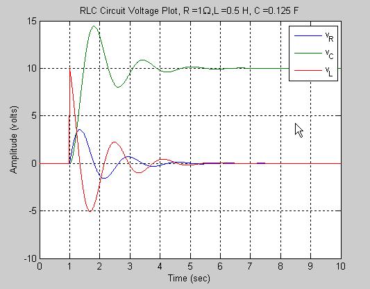
45 Simulation Results
Introduction to Simulink
 Introduction to Simulink by Vinay S. K. Guntu 4310 Feedback Control Systems 1 Simulink Basics Tutorial Simulink is a graphical extension to MATLAB for modeling and simulation of systems. Advantages 1)
Experiment 8 SIMULINK
 Experiment 8 SIMULINK Simulink Introduction to simulink SIMULINK is an interactive environment for modeling, analyzing, and simulating a wide variety of dynamic systems. SIMULINK provides a graphical user
2 SIMULATING A MODEL Simulink Tutorial
 2 SIMULATING A MODEL Simulink Tutorial 1 Introduction Simulation of dynamic systems has been proven to be immensely useful in system modeling and controller design. Simulink R is a add-on to MATLAB which
SIGNALS AND LINEAR SYSTEMS LABORATORY EELE
 The Islamic University of Gaza Faculty of Engineering Electrical Engineering Department SIGNALS AND LINEAR SYSTEMS LABORATORY EELE 3110 Experiment (5): Simulink Prepared by: Eng. Mohammed S. Abuwarda Eng.
Simulink Basics Tutorial
 Simulink Basics Tutorial Simulink is a graphical extension to MATLAB for modeling and simulation of systems. One of the main advantages of Simulink is the ability to model a nonlinear system, which a transfer
BME 5742 Bio-Systems Modeling and Control
 BME 5742 Bio-Systems Modeling and Control Lecture 4 Simulink Tutorial 1: Simulation of the Malthusian and Logistic Models Model Set Up, Scope Set Up Dr. Zvi Roth (FAU) 1 Getting started In the MATLAB command
Experiment 6 SIMULINK
 Experiment 6 SIMULINK Simulink Introduction to simulink SIMULINK is an interactive environment for modeling, analyzing, and simulating a wide variety of dynamic systems. SIMULINK provides a graphical user
SIMULINK Tutorial. Select File-New-Model from the menu bar of this window. The following window should now appear.
 SIMULINK Tutorial Simulink is a block-orientated program that allows the simulation of dynamic systems in a block diagram format whether they are linear or nonlinear, in continuous or discrete forms. To
ECE-205 Lab 1. Introduction to Simulink and Matlab
 ECE-205 Lab 1 Introduction to Simulink and Matlab Throughout this lab we will focus on determining the behavior of a first order system written in the standard form dy( t) y( t) Kx( t) dt where xt () is
Introduction to Simulink
 Introduction to Simulink Mikael Manngård Process Control Laboratory, Åbo Akademi University February 27, 2014 Simulink is an extension to MATLAB that is used for modeling and simulation of dynamic systems.
Simulink Basics Tutorial
 1 of 20 1/11/2011 5:45 PM Starting Simulink Model Files Basic Elements Running Simulations Building Systems Simulink Basics Tutorial Simulink is a graphical extension to MATLAB for modeling and simulation
Lab. Manual. Practical Special Topics (Matlab Programming) (EngE416) Prepared By Dr. Emad Saeid
 (EngE416) Prepared By Dr. Emad Saeid") KINGDOM OF SAUDI ARABIA JAZAN UNIVERSTY College of Engineering Electrical Engineering Department المملكة العربية السعودية وزارة التعليم العالي جامعة جازان كلية الھندسة قسم الھندسة الكھربائية Lab. Manual
KINGDOM OF SAUDI ARABIA JAZAN UNIVERSTY College of Engineering Electrical Engineering Department المملكة العربية السعودية وزارة التعليم العالي جامعة جازان كلية الھندسة قسم الھندسة الكھربائية Lab. Manual
INTRODUCTION TO MATLAB, SIMULINK, AND THE COMMUNICATION TOOLBOX
 INTRODUCTION TO MATLAB, SIMULINK, AND THE COMMUNICATION TOOLBOX 1) Objective The objective of this lab is to review how to access Matlab, Simulink, and the Communications Toolbox, and to become familiar
Introduction to Matlab Simulink. Control Systems
 Introduction to Matlab Simulink & their application in Control Systems ENTC 462 - Spring 2007 Introduction Simulink (Simulation and Link) is an extension of MATLAB by Mathworks Inc. It works with MATLAB
Open Loop Step Response
 TAKE HOME LABS OKLAHOMA STATE UNIVERSITY Open Loop Step Response by Sean Hendrix revised by Trevor Eckert 1 OBJECTIVE The objective is to find a first-order model for a DC motor using the open loop step
Lecture 10: Simulink. What is Simulink?
 Lecture 10: Simulink Dr. Mohammed Hawa Electrical Engineering Department University of Jordan EE201: Computer Applications. See Textbook Chapter 10. What is Simulink? Simulink is a tool for modeling, simulating
Introduction to the MATLAB SIMULINK Program
 Introduction to the MATLAB SIMULINK Program Adapted from similar document by Dept. of Chemical Engineering, UC - Santa Barbara MATLAB, which stands for MATrix LABoratory, is a technical computing environment
Rotary Motion Servo Plant: SRV02. Rotary Experiment #00: QuaRC Integration. Using SRV02 with QuaRC. Student Manual
 Rotary Motion Servo Plant: SRV02 Rotary Experiment #00: QuaRC Integration Using SRV02 with QuaRC Student Manual SRV02 QuaRC Integration Instructor Manual Table of Contents 1. INTRODUCTION...1 2. PREREQUISITES...1
Introduction to Simulink
 Introduction to Simulink There are several computer packages for finding solutions of differential equations, such as Maple, Mathematica, Maxima, MATLAB, etc. These systems provide both symbolic and numeric
Experiment 1 Electrical Circuits Simulation using Multisim Electronics Workbench: An Introduction
 Experiment 1 Electrical Circuits Simulation using Multisim Electronics Workbench: An Introduction Simulation is a mathematical way of emulating the behavior of a circuit. With simulation, you can determine
UNIT 5. Simulink. 1. Introduction
 UNIT 5 Simulink 1. Introduction... 1 2. Simulink... 2 2.1 Starting Simulink... 2 2.2 Model building... 3 2.3 Simulation parameters and Scope block... 5 2.4 Subsystems and masks... 11 2.5 S Functions...
CDA6530: Performance Models of Computers and Networks. Chapter 4: Using Matlab for Performance Analysis and Simulation
 CDA6530: Performance Models of Computers and Networks Chapter 4: Using Matlab for Performance Analysis and Simulation Objective Learn a useful tool for mathematical analysis and simulation Interpreted
UNIVERSITI TEKNIKAL MALAYSIA MELAKA FAKULTI KEJURUTERAAN ELEKTRONIK DAN KEJURUTERAAN KOMPUTER
 UNIVERSITI TEKNIKAL MALAYSIA MELAKA FAKULTI KEJURUTERAAN ELEKTRONIK DAN KEJURUTERAAN KOMPUTER FAKULTI KEJURUTERAAN ELEKTRONIK DAN KEJURUTERAAN KOMPUTER BENC 2113 DENC ECADD 2532 ECADD LAB SESSION 6/7 LAB
Introduction to Simulink. The Use of Mathematic Simulations in Electrical Engineering
 Introduction to Simulink The Use of Mathematic Simulations in Electrical Engineering Lecture Outline 1) Introduction to Simulink 2) Modelling of dynamics systems 2 Simulink Tool for modeling, simulating,
Class #15: Experiment Introduction to Matlab
 Class #15: Experiment Introduction to Matlab Purpose: The objective of this experiment is to begin to use Matlab in our analysis of signals, circuits, etc. Background: Before doing this experiment, students
ME422 Mechanical Control Systems Matlab/Simulink Hints and Tips
 Cal Poly San Luis Obispo Mechanical Engineering ME Mechanical Control Systems Matlab/Simulink Hints and Tips Ridgely/Owen, last update Jan Building A Model The way in which we construct models for analyzing
Introduction to Simulink
 University College of Southeast Norway Introduction to Simulink Hans-Petter Halvorsen, 2016.11.01 http://home.hit.no/~hansha Preface Simulink, developed by The MathWorks, is a commercial tool for modeling,
SIMULINK FOR BEGINNERS:
 1 SIMULINK FOR BEGINNERS: To begin your SIMULINK session open first MATLAB ICON by clicking mouse twice and then type»simulink You will now see the Simulink block library. 2 Browse through block libraries.
CDA6530: Performance Models of Computers and Networks. Chapter 4: Using Matlab for Performance Analysis and Simulation
 CDA6530: Performance Models of Computers and Networks Chapter 4: Using Matlab for Performance Analysis and Simulation Objective Learn a useful tool for mathematical analysis and simulation Interpreted
Developing Customized Measurements and Automated Analysis Routines using MATLAB
 2013 The MathWorks, Inc. Developing Customized Measurements and Automated Analysis Routines using MATLAB Guillaume Millot MathWorks France MathWorks Overview Founded in 1984 in the US Several software
GETTING STARTED WITH ADS
 ADS Startup Tutorial v2 Page 1 of 17 GETTING STARTED WITH ADS Advanced Design System (ADS) from Agilent Technologies is an extremely powerful design tool for many aspects of electrical and computer engineering
Process Automation CHEM-E7140
 Process Automation CHEM-E7140 Tutorial 3: An introduction to Simulink 1 Contents 1 Simulink: a brief introduction...2 A. Getting started...2 B. Modeling dynamic models...3 C. Creating a new model...4 D.
Objectives. Simulink Basics
 Simulink Basics This material exempt per Department of Commerce license exception TSU Objectives After completing this module, you will be able to: Describe Simulink environment List some of the commonly
SIMULINK A Tutorial by Tom Nguyen
 Introduction SIMULINK A Tutorial by Tom Nguyen Simulink (Simulation and Link) is an extension of MATLAB by Mathworks Inc. It works with MATLAB to offer modeling, simulating, and analyzing of dynamical
Manual for Wavenology EM Graphic Circuit Editor. Wave Computation Technologies, Inc. Jan., 2013
 Manual for Wavenology EM Graphic Circuit Editor Wave Computation Technologies, Inc. Jan., 2013 1 Introduction WCT Graphic Circuit Editor is used to build a Spice circuit model in WCT EM full wave simulator.
Session 3 Introduction to SIMULINK
 Session 3 Introduction to SIMULINK Brian Daku Department of Electrical Engineering University of Saskatchewan email: daku@engr.usask.ca EE 290 Brian Daku Outline This section covers some basic concepts
MapleSim User's Guide
 MapleSim User's Guide Copyright Maplesoft, a division of Waterloo Maple Inc. 2001-2009 MapleSim User's Guide Copyright Maplesoft, MapleSim, and Maple are all trademarks of Waterloo Maple Inc. Maplesoft,
MATLAB Premier. Middle East Technical University Department of Mechanical Engineering ME 304 1/50
 MATLAB Premier Middle East Technical University Department of Mechanical Engineering ME 304 1/50 Outline Introduction Basic Features of MATLAB Prompt Level and Basic Arithmetic Operations Scalars, Vectors,
Lab 1 Intro to MATLAB and FreeMat
 Lab 1 Intro to MATLAB and FreeMat Objectives concepts 1. Variables, vectors, and arrays 2. Plotting data 3. Script files skills 1. Use MATLAB to solve homework problems 2. Plot lab data and mathematical
MODELING IN SCILAB: PAY ATTENTION TO THE RIGHT
 powered by MODELING IN SCILAB: PAY ATTENTION TO THE RIGHT APPROACH PART 2 In this tutorial we show how to model a physical system described by ODE using Xcos environment. The same model solution is also
Example: Modeling a Cruise Control System in Simulink
 Example: Modeling a Cruise Control System in Simulink Physical setup and system equations Building the model Open-loop response Extracting the Model Implementing PI control Closed-loop response Physical
[ MATLAB ] [ Resources ] PART TWO: SIMULINK
![[ MATLAB ] [ Resources ] PART TWO: SIMULINK](/thumbs/82/85270175.jpg "[ MATLAB ] [ Resources ] PART TWO: SIMULINK") Página 1 de 15 [ MATLAB ] [ Resources ] PART TWO: SIMULINK Contents Introduction Getting Started Handling of Blocks and Lines Annotations Some Examples NOTE: This tutorial is based on Simulink Version
Página 1 de 15 [ MATLAB ] [ Resources ] PART TWO: SIMULINK Contents Introduction Getting Started Handling of Blocks and Lines Annotations Some Examples NOTE: This tutorial is based on Simulink Version
Experiment 3. Getting Start with Simulink
 Experiment 3 Getting Start with Simulink Objectives : By the end of this experiment, the student should be able to: 1. Build and simulate simple system model using Simulink 2. Use Simulink test and measurement
UNIVERSITI TEKNIKAL MALAYSIA MELAKA FAKULTI KEJURUTERAAN ELEKTRONIK DAN KEJURUTERAAN KOMPUTER
 UNIVERSITI TEKNIKAL MALAYSIA MELAKA FAKULTI KEJURUTERAAN ELEKTRONIK DAN KEJURUTERAAN KOMPUTER FAKULTI KEJURUTERAAN ELEKTRONIK DAN KEJURUTERAAN KOMPUTER BENC 2113 DENC ECADD 2532 ECADD LAB SESSION 6/7 LAB
PSpice with Orcad 10
 PSpice with Orcad 10 1. Creating Circuits Using PSpice Tutorial 2. AC Analysis 3. Step Response 4. Dependent Sources 5. Variable Phase VSin Source Page 1 of 29 Creating Circuits using PSpice Start Orcad
EE 350. Continuous-Time Linear Systems. Recitation 1. 1
 EE 350 Continuous-Time Linear Systems Recitation 1 Recitation 1. 1 Recitation 1 Topics MATLAB Programming Basic Operations, Built-In Functions, and Variables m-files Graphics: 2D plots EE 210 Review Branch
Instrumentation Basics
 ME 125L Spring 2009 Instrumentation Basics M. R. Gustafson II Contents 1 Introduction 2 2 Simulink Demonstration 2 2.1 Starting Simulink........................................... 2 2.2 Basic Blocks and
Copy and paste your LTspice schematic, your MATLAB code, and resulting plots to the document you submit. Please do not use screen capture.
 ECE1 Project Fall 11 First-order project This is a three-part project assignment. This assignment uses the same voltage source as was used in Project 5. The grading total for the 3 parts will be: Part
Guidelines for MATLAB s SISO Design Tool GUI
 Dr. Farzad Pourboghrat Guidelines for MATLAB s SISO Design Tool GUI The SISO Design Tool is a graphical user interface (GUI) that facilitates the design of compensators for single-input, single-output
Assignment 2 in Simulation of Telesystems Laboratory exercise: Introduction to Simulink and Communications Blockset
 Mid Sweden University Revised: 2013-11-12 Magnus Eriksson Assignment 2 in Simulation of Telesystems Laboratory exercise: Introduction to Simulink and Communications Blockset You are expected to conclude
MATLAB Tutorial. Primary Author: Shoumik Chatterjee Secondary Author: Dr. Chuan Li
 MATLAB Tutorial Primary Author: Shoumik Chatterjee Secondary Author: Dr. Chuan Li 1 Table of Contents Section 1: Accessing MATLAB using RamCloud server...3 Section 2: MATLAB GUI Basics. 6 Section 3: MATLAB
CDA5530: Performance Models of Computers and Networks. Chapter 8: Using Matlab for Performance Analysis and Simulation
 CDA5530: Performance Models of Computers and Networks Chapter 8: Using Matlab for Performance Analysis and Simulation Objective Learn a useful tool for mathematical analysis and simulation Interpreted
Lab 1: Analysis of DC and AC circuits using PSPICE
 Lab 1: Analysis of DC and AC circuits using PSPICE 1. Objectives. 1) Familiarize yourself with PSPICE simulation software environment. 2) Obtain confidence in performing DC and AC circuit simulation. 2.
Basics of Keithley Interactive Test Environment
 Basics of Keithley Interactive Test Environment 0 Launching KITE Power Up and Log On ACTION 1. From Power-up: disconnect DUTs, stay clear of SMU output connectors/probes Log-on: KIUSER (no password) or
ELEC ENG 4CL4 CONTROL SYSTEM DESIGN
 ELEC ENG 4CL4 CONTROL SYSTEM DESIGN Lab #1: MATLAB/Simulink simulation of continuous casting Objectives: To gain experience in simulating a control system (controller + plant) within MATLAB/Simulink. To
ECE210 Spice/MATLAB Project 1 Fall 2011 Voltage Divider Analysis and Simulation
 ECE210 Spice/MATLAB Project 1 Fall 2011 Voltage Divider Analysis and Simulation This three-part project assignment will count for 30 homework points. Since the major portion of the project involves a MATLAB
Creates a 1 X 1 matrix (scalar) with a value of 1 in the column 1, row 1 position and prints the matrix aaa in the command window.
 with a value of 1 in the column 1, row 1 position and prints the matrix aaa in the command window.") EE 350L: Signals and Transforms Lab Spring 2007 Lab #1 - Introduction to MATLAB Lab Handout Matlab Software: Matlab will be the analytical tool used in the signals lab. The laboratory has network licenses
EE 350L: Signals and Transforms Lab Spring 2007 Lab #1 - Introduction to MATLAB Lab Handout Matlab Software: Matlab will be the analytical tool used in the signals lab. The laboratory has network licenses
Copyright 2008 Linear Technology. All rights reserved. Getting Started
 Copyright. All rights reserved. Getting Started Copyright. All rights reserved. Draft a Design Using the Schematic Editor 14 Start with a New Schematic New Schematic Left click on the New Schematic symbol
Genesys 2012 Tutorial - Using Momentum Analysis for Microwave Planar Circuits
 Genesys 2012 Tutorial - Using Momentum Analysis for Microwave Planar Circuits Create the following schematics in Figure 1 with Genesys s schematic editor, which depicts two sections of a cascaded microstrip
Department of Physics & Astronomy Lab Manual Undergraduate Labs. A Guide to Logger Pro
 A Guide to Logger Pro Logger Pro is the main program used in our physics labs for data collection and analysis. You are encouraged to download Logger Pro to your personal laptop and bring it with you to
A/D Converter. Sampling. Figure 1.1: Block Diagram of a DSP System
 CHAPTER 1 INTRODUCTION Digital signal processing (DSP) technology has expanded at a rapid rate to include such diverse applications as CDs, DVDs, MP3 players, ipods, digital cameras, digital light processing
xpc Target Tutorial Control System Design Feb. 15, 2004 For more detailed information, see the xpc target manual at:
 xpc Target Tutorial Control System Design Feb. 15, 2004 For more detailed information, see the xpc target manual at: www.mathworks.com Control Hardware Connect to your experiment through the network. xpc
MATLAB AND SIMULINK. Modeling Dynamic Systems J. ABELL
 MATLAB AND SIMULINK Modeling Dynamic Systems J. ABELL Modeling Dynamic Systems Creating a Model Create an Empty Model Create a Model Template Populate a Model Copy Blocks to Your Model Browse Block Libraries
Chapter 4 Determining Cell Size
 Chapter 4 Determining Cell Size Chapter 4 Determining Cell Size The third tutorial is designed to give you a demonstration in using the Cell Size Calculator to obtain the optimal cell size for your circuit
Click on the SwCAD III shortcut created by the software installation.
 LTSpice Guide Click on the SwCAD III shortcut created by the software installation. Select File and New Schematic. Add a component Add a resistor Press R or click the resistor button to insert a resistor.
LTspice Getting Started Guide. Copyright 2007 Linear Technology. All rights reserved.
 Copyright 2007 Linear Technology. All rights reserved. Why Use LTspice? Stable SPICE circuit simulation with Unlimited number of nodes Schematic/symbol editor Waveform viewer Library of passive devices
1. Working with PSpice:
 Applied Electronics, Southwest Texas State University, 1, 13 1. Working with PSpice: PSpice is a circuit simulator. It uses the Kirchhoff s laws and the iv-relation of the used components to calculate
Closed Loop Step Response
 TAKE HOME LABS OKLAHOMA STATE UNIVERSITY Closed Loop Step Response by Sean Hendrix revised by Trevor Eckert 1 OBJECTIVE This experiment adds feedback to the Open Loop Step Response experiment. The objective
Chapter 4: Programming with MATLAB
 Chapter 4: Programming with MATLAB Topics Covered: Programming Overview Relational Operators and Logical Variables Logical Operators and Functions Conditional Statements For Loops While Loops Debugging
SIMetrix/SIMPLIS Library
 SIMetrix/SIMPLIS Library User Manual August 2018 Murata Manufacturing Co., Ltd. Ver. 1.0 1 22 August 2018 Contents Page 1. About this Manual 3 2. Operating Environment 4 3. (Preparation) Library Decompression
Importing Models from Physical Modeling. Tools Using the FMI Standard
 Importing Models from Physical Modeling Tools Using the FMI Standard Overview The objective of this tutorial is to demonstrate the workflow for the integration of FMUs in DYNA4. The following use case
Pre-Lab Excel Problem
 Pre-Lab Excel Problem Read and follow the instructions carefully! Below you are given a problem which you are to solve using Excel. If you have not used the Excel spreadsheet a limited tutorial is given
Note 10 Introduction to MATLAB & SIMULINK
 Note 10 Introduction to MATLAB & SIMULINK Department of Mechanical Engineering, University Of Saskatchewan, 57 Campus Drive, Saskatoon, SK S7N 5A9, Canada 1 1 Introduction to MATLAB MATLAB stands for the
Quick. Efficient. Versatile. Graphing Software for Scientists and Engineers.
 Quick. GrapherTM 3 Efficient. Versatile. Graphing Discover the easy-to-use and powerful capabilities of Grapher 3! Your graphs are too important not to use the most superior graphing program available.
Control Systems Laboratory Manual Hardware and Software Overview. 2 Hardware Equipment. 2.1 Analog Plant Simulator (EE357 Only)
") 1 Introduction Control Systems Laboratory Manual Hardware and Software Overview The undergraduate Control Systems Lab is located in ETLC E5-006. In the lab, there are 15 PCs equipped with data acquisition
1 Introduction Control Systems Laboratory Manual Hardware and Software Overview The undergraduate Control Systems Lab is located in ETLC E5-006. In the lab, there are 15 PCs equipped with data acquisition
Lesson 17: Building a Hierarchical Design
 Lesson 17: Building a Hierarchical Design Lesson Objectives After you complete this lesson you will be able to: Explore the structure of a hierarchical design Editing the Training Root Schematic Making
Simulation examples Chapter overview
 Simulation examples 2 Chapter overview The examples in this chapter provide an introduction to the methods and tools for creating circuit designs, running simulations, and analyzing simulation results.
TUTORIAL SESSION Technical Group Hoda Najafi & Sunita Bhide
 TUTORIAL SESSION 2014 Technical Group Hoda Najafi & Sunita Bhide SETUP PROCEDURE Start the Altium Designer Software. (Figure 1) Ensure that the Files and Projects tabs are located somewhere on the screen.
Can be put into the matrix form of Ax=b in this way:
 Pre-Lab 0 Not for Grade! Getting Started with Matlab Introduction In EE311, a significant part of the class involves solving simultaneous equations. The most time efficient way to do this is through the
Advance Design. Tutorial
 TUTORIAL 2018 Advance Design Tutorial Table of Contents About this tutorial... 1 How to use this guide... 3 Lesson 1: Preparing and organizing your model... 4 Step 1: Start Advance Design... 5 Step 2:
USING THE VENABLE RLC WINDOWS SOFTWARE VERSION 4.5
 USING THE VENABLE RLC WINDOWS SOFTWARE VERSION 4.5 FOR MODELS 350/3120/3215/3225/3235 AND Series 43xx/51xx/63xx/74xx/88xx/350c System Venable Instruments 8656 SH 71 West, Bldg. E Cuesta Center Austin,
Objectives: - You need to be able to use the two equations above and the series and parallel circuit rules.
 F: Solve Complete Circuits Level 3 Prerequisite: Solve Ohm s Law and the Power Formula Points To: Solve Complete Circuit with Nontraditional Information Objectives: V = IR P = IV - Given a battery and
EE 216 Experiment 1. MATLAB Structure and Use
 EE216:Exp1-1 EE 216 Experiment 1 MATLAB Structure and Use This first laboratory experiment is an introduction to the use of MATLAB. The basic computer-user interfaces, data entry techniques, operations,
8438/8838 User Manual User Manual of the 8438/8838 MATLAB Embedded Controllers
 User Manual of the 8438/8838 MATLAB Embedded Controllers Warranty All products manufactured by ICP DAS are warranted against defective materials for a period of one year from the date of delivery to the
TABLE OF CONTENTS INTRODUCTION... 2 OPENING SCREEN BEGIN ANALYSIS... 4 Start a New File or Open a Previously Saved File... 4
 3D-BLAST August 2010 TABLE OF CONTENTS INTRODUCTION... 2 OPENING SCREEN... 3 BEGIN ANALYSIS... 4 Start a New File or Open a Previously Saved File... 4 PROGRAM TOOLBAR... 5 NAVIGATING IN THE PROGRAM...
What Is EPANET. Introduction to EPANET 2.0. EPANET Hydraulic Modeling Capabilities. EPANET Operational Definitions
 What Is EPANET Introduction to EPANET 2.0 Shirley Clark, Penn State Harrisburg Robert Pitt, University of Alabama Performs extended period simulation of hydraulic and water quality behavior within pressurized
Introduction to EPANET 2.0. What Is EPANET
 Introduction to EPANET 2.0 Shirley Clark, Penn State Harrisburg Robert Pitt, University of Alabama What Is EPANET Performs extended period simulation of hydraulic and water quality behavior within pressurized
Mathematical Modelling Using SimScape (Mechanical Systems)
") Experiment Three Mathematical Modelling Using SimScape (Mechanical Systems) Control Systems Laboratory Dr. Zaer Abo Hammour Dr. Zaer Abo Hammour Control Systems Laboratory 1. Translational Mechanical System
Experiment Three Mathematical Modelling Using SimScape (Mechanical Systems) Control Systems Laboratory Dr. Zaer Abo Hammour Dr. Zaer Abo Hammour Control Systems Laboratory 1. Translational Mechanical System
Inlichtingenblad, matlab- en simulink handleiding en practicumopgaven IWS
 Inlichtingenblad, matlab- en simulink handleiding en practicumopgaven IWS 4 SIMULINK 4 Simulink 4 Quick introduction General information Simulink is an etension of Matlab software for simulating dynamic
Lesson 1: Getting Started with OrCAD Capture
 1 Lesson 1: Getting Started with OrCAD Capture Lesson Objectives Discuss design flow using OrCAD Capture Learn how to start OrCAD Capture The OrCAD Capture Start Page Open an existing Project Explore the
You will follow these steps: A. Verify that a student account exists. B. Create a classroom to hold lecture slides.
 In this tutorial, you ll use Biolucida to: Create a virtual lecture Share the lecture with students You will follow these steps: A. Verify that a student account exists. B. Create a classroom to hold lecture
Test 1 - Python Edition
 'XNH8QLYHUVLW\ (GPXQG73UDWW-U6FKRRORI(QJLQHHULQJ EGR 103L Spring 2018 Test 1 - Python Edition Shaundra B. Daily & Michael R. Gustafson II NetID (please print): In keeping with the Community Standard, I
Drill Table. Summary. Modified by Phil Loughhead on 16-Jun Parent page: PCB Dialogs
 Drill Table Old Content - visit altium.com/documentation Modified by Phil Loughhead on 16-Jun-2015 Parent page: PCB Dialogs The Drill Table Dialog. Summary A standard element required for manufacture of
Using Cadence Virtuoso, a UNIX based OrCAD PSpice like program, Remotely on a Windows Machine
 Using Cadence Virtuoso, a UNIX based OrCAD PSpice like program, Remotely on a Windows Machine A. Launch PuTTY. 1. Load the Saved Session that has Enable X11 forwarding and the Host Name is cvl.ece.vt.edu.
Introduction to CS graphs and plots in Excel Jacek Wiślicki, Laurent Babout,
 MS Excel 2010 offers a large set of graphs and plots for data visualization. For those who are familiar with older version of Excel, the layout is completely different. The following exercises demonstrate
Experiment 1: Introduction to PC-Based Data Acquisition and Real-Time Control
 Experiment 1: Introduction to PC-Based Data Acquisition and Real-Time Control Tools/concepts emphasized: Matlab, Simulink, Real-Time-Workshop (RTW), WinCon, MultiQ-3, data acquisition, and real-time control.
Modeling Mechanical System using SIMULINK
 Modeling Mechanical System using SIMULINK Mechanical System We will consider a toy train consisting of an engine and a car as shown in Figure. Assuming that the train only travels in one direction, we
Smith Chart Utility May 2007
 Smith Chart Utility May 2007 Notice The information contained in this document is subject to change without notice. Agilent Technologies makes no warranty of any kind with regard to this material, including,
ELEC 341 Project Selective Laser Sintering 3D Printer The University of British Columbia
 ELEC 341 Project 2017 - Selective Laser Sintering 3D Printer The University of British Columbia In selective laser sintering (SLS), 3D parts are built by spreading a thin layer of metallic powder over
Getting Started with PCB Design
 Getting Started with PCB Design Summary Tutorial TU0117 (v1.2) April 13, 2005 This introductory tutorial is designed to give you an overview of how to create a schematic, update the design information