CD D Image Scanner Advanced Manual
|
|
|
- Lewis Patterson
- 5 years ago
- Views:
Transcription
1 CD D Image Scanner Advanced Manual Version: A0
2 Contents INTRODUCTION GENERAL OPTIONS Restore to Factory Default Settings Switch User Interface and Reset to Default Settings Check Firmware Version Enhance Barcode Scanning on Screens No illumination detection Prevention of flicker Prevention of specular reflection Configure Data Transmission Interval INTERFACE RS232 options Baud rate settings Data, parity and stop bits Handshaking Intercharacter delay for RS Keyboard wedge/usb options Keyboard language Special options Intercharacter delay for wedges/usb CODE OPTIONS Setting of readable codes Enabling a single read. code Enabling of readable codes Setting of number of characters Setting code specific options Options for UPC-A i
3 Options for UPC-E Options for EAN-13 and EAN Options for Code 39 and It. Pharm Options for Codabar Options for 2of5 and S-Code Options for IATA Options for MSI/Plessey Options for Telepen Options for UK/Plessey Options for Code 128 and GS Options for Code Options for Code Options for Korean Postal Authority code Options for Intelligent Mail Barcode Options for POSTNET Options for Composite Codes Options for Codablock F Options for DataMatrix Options for Aztec Options for Chinese Sensible code Options for QR Code Options for Micro QR Code Options for Maxicode Options for PDF Options for MicroPDF STRING OPTIONS Case conversion Set prefix and suffix ii
4 Set prefix Set suffix Direct input keyboard keys Direct input numeric Direct input character Direct input lower case character Direct input control character Direct input code id/length READ OPTIONS Read mode options Multiple read reset time Quiet zone options Auto trigger options Detection Mode Auto Trigger Condition Read time options Redundancy Positive and negative bar codes Floodlight and aiming options Prevention of flicker LED aiming INDICATOR OPTIONS Buzzer settings Good read LED MISCELLANEOUS Diagnostics Serial configuration support APPIX A. TROUBLE SHOOTING iii
5 APPIX B. GLOSSARY OF TERMS iv
6 INTRODUCTION This menu book is intended for setting up your bar code reader to optimize its performance for your particular application. When the required options have been configured, they remain in the reader, even after power down. The reader can be returned to factory default by reading the default label. Menu labels The reader must be set by reading the bar code labels in the menu table. The layout of the table is explained in next figure To have the bar codes properly decoded, keep in mind that you are required to pull a trigger to initiate the decoding process after accurately aiming the scanner at the 1D setup labels
7 Besides options, some chapters have commands. The commands need to be scanned directly, without reading the SET and labels. The commands are executed directly and, unlike options, are not stored in non-volatile memory. Configuring via the menu book To configure the required options proceed as follows: scan the SET label scan the required option(s) scan the label After scanning the label, the new settings are stored in non-volatile memory. Recommended steps to follow for quick configuration After checking your connection you are ready to start the configuration of your reader. Check connection: Ensure that the power is disconnected from your equipment before you connect the reader. After connecting the data cable, the power can be applied to the equipment and the reader. 1: Use chapter 1 to set the correct default for your reader. * The reader is now in factory default. 2: Use chapter 2 to optimize the interface. * The reader is now able to read bar codes and transmit the data. 3: Use chapter 3 to optimize the reader for the type of bar codes you use. Set the readable codes first and then the options for each of these codes. * The reader is now able to read the codes you selected, validate the data using length and check digit and transmit that part of the data you specified. 4: Use chapter 4 to select the string options for your application. These include transmission of code length, conversion of upper and lower case and setting a prefix and suffix. * The reader can now read and transmit the data in the required format. 5: Use chapter 5 to select the read options to your preference. These options affect the read mode, read time, trigger and redundancy
8 6: Use chapter 6 to select the indicator options you prefer. These options affect the operation of the buzzer and good read LED. * The reader will now operate to your personal preference. See figure Configuring via RS232 In the middle column of the menu pages the command is printed, e.g. U2. These commands can be sent to readers with an RS232 interface. To configure via the RS232 port proceed as follows: transmit <ESC><Command string 1><CR> transmit <ESC><Command string 2><CR> transmit <ESC><Command string n><cr> transmit <ESC>Z2<CR> <ESC> <ESC> is the ASCII escape character (Hex 1B). <Command string> <Command string> is the ASCII command with its parameters as would be scanned from the menu book, i.e. <ESC>M41B<CR> configures the ASCII control code <STX> as the prefix for Code 39. Example in hexadecimal format: 1B 4D B ØD - 3 -
9 Each 3-character command should be preceded with the '[' character (Hex 5B) i.e. <Esc>[BCC<CR> is used to enable Data Matrix. Each 4-character command should be preceded with the ']' character (Hex 5D) i.e. <Esc>]DIAU<CR> is used to disable auto connect. <CR> <CR> is the ASCII CR character (Hex ØD). Z2 Some options are not immediately active, like baud rate settings. Most other options are immediately active, but the command Z2 must be send to store the settings to non-volatile memory. The following commands may be used to: Command B sound a good read beep Command E sound an error beep Command G motor off Command H motor on Command L switch on good read LED Command N switch on bad read LED Command O switch on both LEDs Command Y de-trigger the reader Command Z trigger the reader The characters transmitted must be separated by an intercharacter delay to allow the reader to process each character received and to execute the command string. Package Content CD-3200U CD-3200U 2D Image Scanner ST-8000 scanner holder stand (Optional) USB cable Quick setup guide for CD-3200U/R CD-3200R CD-3200R 2D Image Scanner ST-8000 scanner holder stand (Optional) RS-232 cable Quick setup guide for CD-3200U/R - 4 -

10 1. GENERAL OPTIONS 1.1. Restore to Factory Default Settings This option allows you to undo all previously configured options and bring the reader's configuration back to factory default settings. These factory default settings are printed in bold. Note that differences may occur depending on the type of interface as will be mentioned in the text. Select only the correct default settings corresponding to your hardware "defaults" label. The interfaces supported depend on the reader model and software release. Please consult your sales office for not listed interfaces. RS232 USB-HID USB-VCP - 5 -
11 1.2. Switch User Interface and Reset to Default Settings This option allows you to switch among multiple interfaces supported by CD-3200 series 2D Image reader, including USB HID, USB Virtual COM, and RS-232, according to your needs. And, the current settings will be automatically reset to factory default settings once the user interface is changed. To verify your configuration, it is strongly advised for CD-3200U and CD-3200R users to unplug and then re-plug the cable after the relevant barcode labels are scanned. Otherwise, you may also try to reboot the terminal to achieve the purpose. If it still fails to change user interface, please be advised to scan the barcode again after either re-plugging your scanner or restarting your terminal. RS232 USB-HID USB-VCP 1.3. Check Firmware Version This options allows you to retrieve the current firmware version. Firmware Version 1.4. Enhance Barcode Scanning on Screens In addition to the printed barcodes, you may also aim the scanner at the desired barcode on screens to scan and decode barcodes. This section lists three adjustable options which are all designed to improve efficiency in scanning barcodes directly from screens
12 1.4.1 No illumination detection With no illumination detection, a target code is detected without illumination light. The power consumption can be reduced, but the response of detection will also be reduced. Ambient light is used for detection in this mode, so this can not be used in a dark place while it can be used in a lighted environment. SET No illumination detection DDI Prevention of flicker When there is no target to be read, flicker occurs because of the LED illumination, and this flicker can be prevented with setting. However, it is normally suggested not to enable LED illumination flicker prevention, a feature which will make it difficult to read barcodes on LCD screens once activated. SET Enable LCD display reading D3J Prevention of specular reflection Only when specular reflection of LED illumination occurs, the reading is performed with the illumination turned off, which will lead to degradation of reading performance. SET Prevent specular reflection D3Q - 7 -
13 1.5. Configure Data Transmission Interval This option allows you to specify the interval at which the scanned data will be transferred. In other words, this will determine how fast you want the scanned data to be transmitted. How to set data transmission interval: Please follow the example below to scan the sequence of barcode labels to set the data transmission interval to be 2 ms: <SET> <USB HID Transfer Interval> <binterval=2> <> SET USB HID transfer interval binterval = 1 E9M Q1 binterval = 2 Q2 binterval = 4 Q4 binterval = 8 Q8-8 -
14 2. INTERFACE This chapter describes the configurable transmission options for your reader. Some options may not be relevant to the type of reader you have. An attempt to configure the reader for such options does not affect its operation and usually results in the reader producing an error tone, indicating you tried to make an illegal configuration entry RS232 options This paragraph describes the specific options for a reader with an RS232 interface. Bar code readers with an RS232 interface are normally supplied with either a DB25 or DB9 female connector. Both connectors are fitted with an external power connector. See figure 2.01 or Other connectors and/or connections are available by special order. Pin functions as seen from the bar code reader. FG: Frame Ground: This is normally connected to the "chassis ground" at the host computer. In the RS232 specification the use of FG is optional. TxD: Transmitted Data: Transmits data from the reader to the host. This connection is mandatory. RxD: Received Data: Receives data from the host to the reader. This connection is required if you want to send commands to the bar code reader or if software handshaking or acknowledgement control is used. RTS: Request To Send: A general purpose output to the host, used for hardware flow control. This connection is optional
15 CTS: Clear To Send: A general purpose input to the bar code reader, used for hardware flow control. This connection is optional. SG: Signal Ground: Reference point for power supply and interface signals. This connection is mandatory Baud rate settings The baud rate is the rate at which bits are transmitted from the reader to the host, and vice versa. Both the reader and the host should be set to the same baud rate. SET 300 baud K1 600 baud K baud K baud K baud K baud K baud K baud K baud K baud SZ

16 Data, parity and stop bits The data characters may be transferred in one of the following formats: A parity bit may be added to every character so that the total number of 1's in the data bits, together with the parity bit, is odd for odd parity or even for even parity. See figure SET 7 data bits L0 L1 L2 Even parity L3 Odd parity L4 L5 2 stop bits L6-11 -
17 Handshaking Data flow control is available using either hardware (Modem, Busy/Ready) or software (XON/XOFF). In addition, an optional acknowledgement control is available (ACK/NAK with or without error response). Flow control may be combined with acknowledgement control. The RS232 voltage levels employed by most readers for transmission are either -10V (OFF) or +10V (ON). 1. No handshake: Does not employ any handshaking: data is transmitted regardless of the control signals. This option will undo any handshake and flow control options selected. 2. Modem mode: The reader's RTS is OFF as soon as power is supplied to the reader. The reader will turn RTS ON when it wants to transmit data to the host. The host should respond by putting CTS ON when it is ready to receive data. While CTS is ON the reader is allowed to transmit data. When all data has been transmitted, the reader will turn RTS OFF. In response, the host should turn OFF the reader's CTS. If, while RTS is ON, the CTS line is not ON for a certain configurable period, the reader will terminate the transmission with an error indication of the buzzer. See figure ACK/NAK: After data has been transmitted, the reader expects to receive one of the following responses from the host: Response: "ACK" (ASCII: Hex O6) Action: The reader completes transmission with the good-read buzzer. Response: "NAK" (ASCII: Hex 15) Action: The reader sends the data again. Response: "DC1" (ASCII: Hex 11) Action: The reader completes transmission without a good-read or error buzzer. Response: "None"
18 Action: If there is no response within one second then the reader terminates transmission with an error buzzer. See figure ACK/NAK no response: The difference from the ACK/NAK mode is that when no response from the host is received within 100 ms, the reader assumes that the data has been received correctly by the host. Response: "ACK" (ASCII: Hex O6) Action: The reader completes transmission with the good-read buzzer. Response: "NAK" (ASCII: Hex 15) Action: The reader sends the data again. Response: "DC1" (ASCII: Hex 11) Action: The reader completes transmission without a good-read or error buzzer. Response: "None" Action: If there is no response within 100 ms, then the reader terminates transmission with a good read buzzer. See figure
19 Handshaking barcode setting SET Modem P2 ACK/NAK P3 ACK/NAK NO RESPONSE P4 Flow Control time out 100ms I1 Flow Control time out 200ms I2 Flow Control time out 400ms I3-14 -
20 Intercharacter delay for RS232 The intercharacter delay introduces a configurable time delay after each character transmitted. This may be used if the connected computer or terminal does not support flow control and is not capable of handling the received data. SET KA 20 ms delay KB 50 ms delay KC 100 ms delay KD 2.2. Keyboard wedge/usb options This paragraph describes the options which are relevant to readers with a wedge or USB interface. The following parameters can be configured: keyboard language special options intercharacter delay Because these options are interdependent, it is important to perform the configuration in the sequence given. Please consult your sales office for keyboard layouts and language currently supported. Keyboard wedge operation modes: This mode enables or disables responses from PC wedge to the computer during booting. In normal cases, the keyboard handles the responses to the computer. The PC wedge is only listening in order to be aware of the keyboard state. With keyboard: Use this mode in case a keyboard is connected to the PC wedge Y-cable. The wedge is only listening in case the computer is booting or when the wedge is idle
21 Without keyboard: Use this mode in case no keyboard is connected to the PC wedge Y-cable. In some cases this mode is required in case only a PC USB keyboard is connected. If this option is enable, the computer can detect the wedge as a keyboard. In case the computer reports a keyboard error or in case no data is displayed, try this option. It is required to power OFF the PC, wait 10 seconds and power ON the PC again. Do not enable this option in case a keyboard is connected to the Y-cable. The wedge is responding to all commands from the computer. The without keyboard option is only supported for PC/AT wedges. SET KM Without keyboard KL Keyboard language Keyboards are also different depending on country or language. Examples are the QWERTY and AZERTY keyboards. Select the same language that has been selected on your PC. The languages supported depend on the reader model and software release. Please consult your sales office for the languages currently supported. SET UK KV German KG French KI French Macintosh BAO
22 Italian OW Spanish KJ Portuguese PH Swiss ( French ) PL Swiss ( German ) PK Dutch PI Belgian PJ Swedish PD Finnish PG Danish KK Norwegian PE Japanese PM Czech WF Special options This section contains some specialized keyboard options. Do not use numpad: The reader wil emulate the numerical keys on the alpha keypad when transmitting numerical data. Use numpad: The reader will emulate the numerical keypad when transmitting numerical data. The NUMLOCK should always be ON when this option has been selected
23 Auto NumLock mode: When selecting this option, the bar code reader automatically uses the correct NumLock state. No CAPSLOCK mode: This options cancels the CAPSLOCK mode. CAPSLOCK mode: This option ensures that data is displayed correctly when the keyboard is normally in CAPSLOCK mode. The keyboard is returned in the CAPSLOCK mode after transmission. Auto CAPSLOCK mode: When selecting this option, the transmitted data is displayed correctly, disregarding the CAPSLOCK state. SET Use numpad RM Auto numlock mode /A CAPSLOCK mode 8A CAPSLOCK mode 2U
24 Intercharacter delay for wedges/usb The intercharacter delay can be used to adapt the reader's data transmission speed to the system. If the transmission speed is too high, the system may not be able to receive all characters. Adjust the intercharacter delay until the data is received correctly. The default value as well as the actual delay time depend on the terminal type and language selected. SET No delay LA Delay = 1 LB Delay = 2 LC Delay = 3 LD Delay = 4 LE Delay = 5 LF Delay = 6 LG Delay = 7 LH Delay = 8 LI Delay = 9 LJ Delay = 10 LK
25 3. CODE OPTIONS The menu options in this chapter are intended to adjust the decoding settings of the reader: which bar code types can be read the permissible length of the bar codes to be read bar code specific options Note: This manual categorizes the barcodes as groups of different symbologies with their translations and sometimes with relations to other family names. The next figure visualizes how code translations and relations are maintained in this Code options chapter. See figure
26 3.1. Setting of readable codes These options do not affect the reading of the menu labels. The required bar code types can be selected by enabling a single readable code only and enabling readable codes. It is strongly recommended to select only the required codes. Advantages of selecting only the required codes are: faster reading no accidental scanning of unwanted bar codes reduced probability of reading errors which cannot be prevented completely, because of the limited security of some bar code types Some bar codes are translations or special variants of other bar code types. The table on the title page of this chapter visualizes these relations. The setting of different codes is explained in the next chapter Enabling a single read. code Enabling a single read. code With this option you can set the reader to read a single bar code type only. If you select 'Code 39 only', no other codes will be read. Example 1: If you want to read Code 39 only, you read the option 'Code 39 only'. See figure Example 2: If you want to read one of the special bar codes that is a variation of the readable code, read the single read. code option followed by the dedicated variation option from the applicable symbology options chapter. EAN128 only: read the option 'Code 128 only' followed by 'Enable EAN-128 only' from the 'Options for Code 128'. Italian Pharmaceutical: read Enable Code 39 only, followed by the option 'Italian Pharmaceutical only' from the 'Options for Code 39'

27 See figure Example 3: If you want to read a code that is changed to another family name, read the new name. RSS+14: read the option GS1 Databar. See figure Enabling a single read. code SET All codes excl. add-on A0 Only all UPC and EANcodes J0 UPC only J1 UPC + 2 only J2-22 -
28 UPC + 5 only J3 EAN only J4 EAN + 2 only J5 EAN + 5 only J6 Code 39 only A2 Tri-Optic only JD Codabar only A3 Industrial 2of5 only J7 Interleaved 2of5 only J8 S-Code only RA Matrix 2of5 only AB Chinese Post Matrix 2of5 only JE Korean Postal Authority code only JL Intelligent Mail Barcode only D5H POSTNET only D6C IATA only A4 MSI/Plessey only A7 Telepen only A9-23 -
29 UK/Plessey only A1 Code 128 only A6 Code 93 only A5 Code 11 only BLB GS1 DataBar only J9 GS1 DataBar Limited only JJ GS1 DataBar Expanded only JK Codablock F only D4R DataMatrix ECC only BG2 DataMatrix ECC200 only BC0 Aztec only BC5 Aztec runes only BF4 Chinese Sensible code only D4K QR Code only BC1 Micro QR Code only D38 Maxicode only BC2 PDF417 only BC3 MicroPDF417 only BC4-24 -
30 Enable all 1D codes only BCA Enable all 2D codes only BCB Enabling of readable codes With this option you can set the reader to read a number of bar code types or simply enable additional bar code types. Example: If you only want to read Code 39 and Code 128, you read 'Code 39 only' and 'enable Code 128'. Alternatively you can read 'Disable All', 'Enable Code 39' and 'Enable Code 128'. See figure Example of addition: If you want to enable Codabar in addition to what you already have configured, you read 'Enable Codabar'. See figure
31 Enabling of readable codes SET All codes excl. add-on A0 Enable UPC + 2 R2 Enable UPC + 5 R3 R4 Enable EAN + 2 R5 Enable EAN + 5 R6 Enable Matrix 2of5 BB Enable Chinese Post Matrix 2of5 Enable Korean Postal Authority code Enable Intelligent Mail Barcode JS WH D5F
32 Enable POSTNET D6A Enable Code 11 BLC Enable GS1-Databar JX Enable GS1-Databar Limited Enable GS1-Databar Expanded JY DR Enable Codablock F D4P Enable DataMatrix ECC BG0 Enable Aztec runes BF2 Enable Chinese Sensible code D4L
33 Enable all 1D codes BCM Enable all 2D codes BCN Disable all B Setting of number of characters If you are going to read bar codes of known length, it is recommended to set the reader for a fixed number of characters. This can be done for up to two lengths. The reader uses this to verify that labels read are of the correct length, rejecting any labels which do not have the specified length. The advantage of setting a fixed length, is that it provides protection against short scans of labels, such as Interleaved 2of5, which do not provide sufficient security against partial scan. The length checking is done on the label data and is not affected by options such as (not) transmit start/stop character or check digit. Setting the number of characters does not affect fixed length codes, such as EAN-13. 2D symbologies such as PDF417 and Data Matrix are also not affected by fixed length settings. The following options are available: Fixed length OFF all codes. This option cancels the fixed length checking
34 Fixed length ON all codes. This option enables the fixed length checking. Two fixed lengths are programmed which will affect all variable length codes. This is done by reading the following labels: <SET> <Fixed length ON - all codes> a bar code with the required length, a second bar code with the required length (this may be the same length as the first one) <> See figure It is possible to configure a fixed length or a minimum and a maximum length for selected symbologies by reading the respective option followed by a barcode label with the required length. The different functions may be combined and will be used as follows: if a label is checked for fixed length, it will not be checked for minimum or maximum length if a label is not checked for fixed length it will be checked for both minimum and maximum length By reading an option followed by the '' label, the function is disabled or the values for that option are reset to their default. The default values are: fixed: disabled, thus no fixed length checking minimum: according to the next figure (The minimum length of the 2of5 bar code types can not be changed independent.) maximum: disabled, thus no maximum length checking. (The maximum length is reader dependent)
35 See figure Fixed length ON for selected codes: This option enables fixed length checking for different bar code types and will only affects the bar code types read. The number of fixed lengths which can be configured is reader dependent. <SET> <Fixed length ON for selected codes> Scan bar codes of the required type and length <> Example: The 2 examples shown in the next figure have the following results: In the first example only Code 39 labels will be checked for a length of 6 characters. Any other bar code type will not be checked for fixed length. In the second example Code 39 labels will be checked for a length of 6 characters and interleaved 2of5 labels for a length of 12 characters. This implies that also Industrial 2of5, Matrix 2of5 and S-Code are checked for a fixed length of 12 characters. Any other bar code type will not be checked for fixed length. See figure
36 Minimum length for selected codes: This option modifies the default minimum length table. The number of minimum lengths which can be configured is reader dependent. This is done by reading the following labels: <SET> <Minimum length for selected codes> Scan bar codes of the required type and length <> Example: The two examples shown in the next figure have the following result: In the first example only Code 39 labels will be checked for a minimum length of 2 characters. All other bar code types will be checked for a minimum length as displayed in the next figure. In the second example Code 39 labels will be checked for a minimum length of 2 characters and interleaved 2of5 labels for a minimum length of 4 characters. This implies that also Industrial 2of5, Matrix 2of5 and S-Code are checked for a minimum length of 4 characters. All other bar code types will be checked for a minimum length as per figure Maximum length for selected codes: This option enables the maximum length checking. The number of maximum lengths which can be configured is reader dependent. This is done by reading the following labels: <SET> <Maximum length for selected codes> Scan bar codes of the required type and length <>
37 Example: The two following examples shown in the next figure have the following result: In the first example only Code 39 labels will be checked for a maximum length of 12 characters. Any other bar code types will not be checked for a maximum length. In the second example Code 39 labels will be checked for a maximum length of 12 characters and Interleaved 2of5 labels for a maximum length of 14 characters. This implies that also Industrial 2of5, Matrix 2of5 and S-Code are checked for a maximum length of 14 characters. Any other bar code types will not be checked for a maximum length. See figure Serial programming: To set a length using serial commands, the sequence is as follows: <ESC> <command> <SPACE>*<CodeID>* <Length 1> <Length 2**> <CR> *(if required by <command>) **(length 2 may be the same length as length 1, when only one length is required) Example: Setting fixed length for all codes, lengths 8, 10 and 12: <ESC>H <CR> Setting minimum length for selected codes, for Code 39 with a length of 2:
38 <ESC>HL V02<CR> Setting maximum length for selected codes, for Code 39 with a length of 12 and Interleaved 2of5 with length of 14: <ESC>HM V12 N14<CR> Setting of number of characters SET Fixed length ON all codes Fixed length ON for selected codes Minimum length for selected codes Maximum length for selected codes H1 HK HL HM 3.3. Setting code specific options Code specific options may be configured affecting: enabling and disabling code variants and translations, such as EAN-128, as were listed in the relations table for setting of readable codes data verification such as by means of a check digit calculation. A check digit has a value that can be calculated from the other data characters and is usually the last data character in a bar code pre-editing of the data string such as removing the check-digit and/or start/stop characters The more common options are described here: Check CD: This option enables the check digit calculation. If the calculated check digit does not correspond to the check digit in the bar code, then the bar code is ignored. The use of a check digit greatly improves the security of a bar code. Not check CD: This option disables the check digit calculation. This option is required when the bar codes do not contain a check digit or contain an invalid check digit
39 Transmit CD: This option enables the transmission of the check digit together with the data characters. If the check digit calculation is disabled, the reader can not differentiate anymore between a (valid) check digit and a data character. It will therefore transmit all data characters of the label, including what could constitute a check digit. Not transmit CD: This option disables the transmission of the check digit. If the check digit calculation is disabled, the reader can not differentiate between a (valid) check digit and a data character. It will therefore transmit all data characters of the label, excluding the character that could constitute the check digit for the type of bar code. Transmit ST/SP: This option enables the transmission of the start and stop characters of a bar code. Not transmit ST/SP: This option disables the transmission of the start and stop characters of a bar code. The next figure summarizes the effect of the transmit options for a Code 39 label with: start and stop characters '*' data characters ' ' or data characters ' ' and check digit '6' Note that because '6' is, according to the Code 39 specifications, not a valid check digit for this label. The check digit calculation must therefore be disabled in order for the label to be accepted. See figure Options for UPC-A The UPC-A symbology is a fixed length symbology encoding 11 data digits, a check digit and non-printable start/stop characters. The following characters are supported: the digits 0 up to 9 An optional leading zero can be transmitted, which together with the data and the check digit forms a 13 digit field providing compatibility with the EAN-13 format. For string format see figure
40 UPC-A add-on 2/add-on 5: The UPC-A symbology as described above can be succeeded by an additional 2 or 5 digit UPCA code. For string format see figure Options for UPC-A: disable transmission of the leading zero disable transmission of the check digit SET UPC-A, No leading zero, not transmit CD E5 UPC-A, Leading zero, transmit CD E2 UPC-A, Leading zero, not transmit CD E Options for UPC-E The UPC-E symbology is a fixed length symbology encoding 6 data digits, a check digit and non printable start/stop characters. The following characters are supported: the digits 0 upto 9 An optional leading digit can be transmitted, which together with the data and the check digit forms an 8 digit field providing a compatibility with the EAN-8 format
41 For string format see figure UPC-E add-on 2/add-on 5: The UPC-E symbology as described above can be succeeded by an additional 2 or 5 digit UPCE code. For string format see figure UPC-E0 stands for UPC version E0 and the first digit is always a '0'. UPC-E1 stand for UPC version E1 and the first digit is a '1'. Options for UPC-E0 affects UPC-E1 too. Support for UPCE1 is reader dependent. Options for UPC-E: enable transmission of the leading digit disable transmission of the check digit transmit UPC-E as UPC-A Transmit UPC-E as UPC-A: If this option is enabled, a UPC-E label is transmitted in the UPC-A format. Options for UPC-E SET UPC-E, No leading E9 digit, not transmit CD UPC-E, Leading digit, E6 transmit CD
42 UPC-E, Leading digit, E8 not transmit CD Transmit UPC-E as 6P UPCA Options for EAN-13 and EAN-8 EAN-13: The EAN-13 symbology is a fixed length symbology encoding 12 data digits, a check digit and non-printable start/stop characters. The following characters are supported: the digits 0 upto 9 The data may be translated into ISBN, ISSN or ISMN format. For string format see figure EAN-13 add-on 2/add-on 5: The EAN-13 symbology as described above can be succeeded by an additional 2 or 5 digitcode. For string format see figure EAN-8: The EAN-8 symbology is a fixed length symbology encoding 7 data digits, a check digit and non-printable start/stop characters. The following characters are supported: the digits 0 upto
43 For string format see figure EAN-8 add-on 2/add-on 5: The EAN-8 symbology as described above can be succeeded by an additional 2 or 5 digit code. For string format see figure Options for EAN: disable transmission of the check digit enable ISBN, ISSN or ISMN translation Enable ISBN, ISSN or ISMN translation: If this option is enabled, an EAN-13 label is verified for the correct format and transmitted as a 10-digit ISBN number, 8 digit ISSN number. In case of ISMN, the character M is transmitted followed by 9 digits. Support for these translations is reader dependent
44 Options for EAN-13 and EAN-8 SET EAN-13 not transmit CD 6J EAN-8 not transmit CD 6H Enable ISBN translation IA Enable ISBN if possible IK Enable ISSN translation HO Enable ISSN if possible 4V Enable ISMN translation IP Enable ISMN if possible IQ
45 Options for Code 39 and It. Pharm. Code 39: Code 39 is a variable length symbology with an optional check digit and printable start/stop characters. The following characters are supported: the digits 0 up to 9 the upper case characters A up to Z the characters -. $ / + % SPACE start/stop character is * The checksum is calculated as the sum modulo 43 of the numerical value of the data characters. In full ASCII mode, all 128 ASCII characters are supported. This is done by combining one of the characters +, %, $ or / with one of the alpha characters (A upto Z). For string format see figure Italian Pharmaceutical: In this mode the Code 39 data is translated to the Italian pharmaceutical format. This format has a fixed length containing 8 numeric data values followed by a single mandatory check digit. An optional leading 'A' can be transmitted. For string format see figure Options for Code 39: enable full ASCII conversion enable Italian Pharmaceutical conversion enable check digit disable transmission of the check digit enable transmission of start/stop enable leading A for Italian Pharmaceutical selection of the minimum number of data characters
46 Normal Code 39: In this mode the decoded data characters are transmitted without further translation. Full ASCII Code 39: In this mode the decoded data characters are translated to full ASCII Code 39. Full ASCII Code 39 if possible: In this mode the decoded data characters are translated to full ASCII Code 39. Invalid combinations are not translated and are transmitted as is. Italian Pharmaceutical only: In this mode the decoded data characters are translated to the Italian Pharmaceutical format. If the data does not comply with the Italian Pharmaceutical format, the label is rejected. Italian Pharmaceutical if possible: In this mode the decoded data characters are translated to the Italian Pharmaceutical format. If the data does not comply with the Italian Pharmaceutical format, then the data is transmitted as Normal or full ASCII Code 39. Tri-Optic: This fixed length symbology builds its data out of two data triplets, where the second triplet is encoded at first. The following characters are supported: the digits 0 up to 9 the upper case characters A up to Z the characters -. / + % SPACE start/stop character is $ For string format see figure There are no options for Tri-Optic supported. Concatenation: If a Code 39 bar code contains a leading space, the data is stored into the reader's buffer without the leading space. As soon as a Code 39 bar code is read without a leading space, the data is appended to the reader's buffer and the entire buffer is transmitted and cleared for new data. In case a non Code 39 bar code is read, the data in the non-code 39 bar code is transmitted and the buffer is cleared. The buffer size is reader dependent
47 Options for Code 39 and It.Pharm. SET Full ASCII Code 39 D4 Full ASCII Code 39 if possible +K It. Pharmaceutical only D6 It. Pharmaceutical if possible D7 Check CD C0 Not transmit CD D8 Transmit ST/SP D0 Transmit leading A for It. Pharm.Code DB Minimum 3 digits 8D
48 Enable concatenation +L Options for Codabar Codabar (NW7): Codabar (NW7) is a variable length symbology with an optional check digit and printable start/stop characters. The next characters are supported: the digits 0 upto 9 the characters - $: /. + start/stop characters are A, B, C or D The checksum is calculated as the sum modulo 16 of the numerical values of all data characters. For string format see figure ABC-Code: The ABC code is an acronym for American Blood Commission. This code consists of two bar codes which are decoded in one read cycle. The code is concatenated when the stop character of the first bar code and the start character of the second bar code is a D. These two D's are not transmitted. For string format see figure CX-Code: The CX-Code consists of two bar codes which are decoded in one read cycle. The code is concatenated when the stop character of the first bar code is a C, and the start character of the second bar code is a B. The B and C characters are not transmitted
49 For string format see figure Options for Codabar: enable ABC code concatenation enable CX code concatenation enable check digit check disable transmission of the check digit disable transmission of start/stop selection of start/stop character translation selection of minimum number of data characters enable library space (CLSI) insertion Space insertion: This option inserts spaces in position 2, 7, 13, of the data string for use in library systems. ST/SP translation: This option enables the translation and transmission of the start and stop characters. Thus if the option ST/SP: abcd/tn*e is chosen, the start character is converted to lower case, e.g. from A, B, C or D to a, b, c, or d respectively and the stop character is converted from A, B, C or D to t, n, *, or e respectively. The next figure shows the resulting format for these options with a Codabar label using A and B as start and stop characters and as data characters. For string format see figure
50 Minimum data characters: Codabar labels are checked for a minimum of 1, 3 or 5 characters are set by the user. If the number of characters in the label is shorter than the number set, the label will be rejected. If the fixed length option is used for Codabar type labels then such labels will additionally be checked for fixed length. Inter character gap check: This option enables the reading of Codabar labels with a large or irregular gap between characters. Checking the gap means that it is not allowed to have a gap. Disable the gap check allows gaps in the bar code. Options for Codabar SET Enable only ABC code H4 Enable only CX code H5 Enable Codabar, ABC and CX H3 Check CD H6 Not transmit CD H9 Enable space insertion HD ST/SP: ABCD/ABCD F3-45 -
51 ST/SP: abcd/abcd F4 ST/SP: ABCD/TN*E F1 ST/SP: abcd/tn*e F2 ST/SP: HJ <DC1><DC2><DC3><DC4>/ <DC1><DC2><DC3><DC4> Minimum data one character HC Minimum data three characters HB Disable intercharactergap HI check Options for 2of5 and S-Code Code 2of5: Code 2of5 is a variable length symbology with an optional check digit and non-printable start and stop characters. The following characters are supported: the digits 0 upto 9 The checksum is calculated as the sum modulo 10 of the numerical values of all the data characters. Industrial 2of5: This symbology encodes a single digit in each data symbol. Information is carried in the bars only

52 Interleaved 2of5: This symbology encodes a pair of digits in each symbol, the number of digits are therefore always an even number. Information is carried in the bars and spaces. The start and stop pattern is not unique inside the code. It is therefore essential to use the fixed length option to prevent partial reads. S-Code: This symbology encodes like Interleaved 2of5 but encodes the last data character as Industrial 2of5. The number of data digits is therefore always an odd number. Information is carried in the bars and the spaces. The start and stop pattern is not unique inside the code. It is therefore essential to use the fixed length option to prevent partial reads. Matrix 2of5: This symbology encodes 1 digit in each character, the number of digits can therefore be an odd or an even number. Information is carried in the bars and spaces. Chines Post Matrix 2of5: This symbology is a variant of Matrix 2of5. To assure proper reads, check the options and setting for (Matrix) 2of5. For string format of the supported symbologies see figure Options for code 2of5: disable transmission of the check digit enable check digit check selection of the minimum number of data characters disable space check for industrial 2of5 transmit S-Code as Interleaved 2of5 Minimum data characters: Code 2of5 are checked for a minimum of 1, 3 or 5 characters as set by the user. If the number of characters in the label is less than the number set, the label will be rejected. If the fixed length option is used for a Code 2of5 type label, than such label will additionally be checked for fixed length
53 Space check: This option enables the reading of Industrial 2of5 labels with a large or irregular spacing. Transmit S-Code as Interleaved 2of5: This option enables to transmit S-Code as Interleaved 2of5 by adding a leading zero. SET Not transmit CD E1 Check CD G1 Minimum data one GE character Minimum data three GF character Disable space check GK for Industrial 2of5 Transmit S-Code as GG Interleaved 2of5-48 -

54 Options for IATA The IATA code is a variable length symbology with an optional check digit and non-printable start/stop characters. The following characters are supported: the digits 0 upto 9 The checksum is calculated as the modulo seven of the data string. IATA is acronym for International Air Transport Association. For string format see figure SET Check FC and SN 4I only Check CPN, FC and 4J SN Check CPN, AC, FC 4K and SN Not transmit CD 4M Options for MSI/Plessey MSI Plessey is a variable length symbology with one or two optional check digit calculations CD1 and CD2 and non-printable start/stop characters. The following characters are supported: the digits 0 up to 9 The checksum is calculated as the sum modulo 10 or 11 of the data characters. The checksum CD2 is calculated as the sum modulo 10 or 11 of the data characters and CD1. For string format see figure
55 Options for MSI/Plessey: disable check digit check selection of the check digit calculation selection of the number of check digits to be transmitted Check digit: If the check digit calculation is required, then the appropriate calculation method must be selected. Not transmit CD: The character positions CD1 and CD2 are not transmitted. Transmit CD1: The character position CD2 is not transmitted. Transmit CD1 and CD2: All characters in the label are transmitted. SET Not check CD 4A Check 2 CD's = 4C MOD 10/MOD 10 Check 2 CD's = 4D MOD 10/MOD 11 Check 2 CD's = 4R MOD 11/MOD 10 Not transmit CD 4G

56 Transmit CD1 and 4F CD Options for Telepen Telepen is a variable length symbology with a check digit and non printable start/stop characters. The following characters are supported: in numeric mode, the digits 00 upto 99 in full ASCII mode, all 128 ASCII characters The check digit calculation is derived from the sum of all data characters modulo 127. The check digit cannot be transmitted. For string format see figure Options for Telepen: selection of ASCII mode SET ASCII mode D3-51 -
57 Options for UK/Plessey UK Plessey is a variable length symbology with a mandatory checksum and non printable start/stop characters. The following characters are supported: the digits 0 upto 9 the characters A upto F The checksum contains 2 digits and is calculated from the numerical values of all the data digits. For string format see figure Space insertion: This option inserts spaces in position 2, 5, 11, 14 of the data string for use in library systems. A to X conversion: This option converts the character 'A' into an 'X'. The data and check digits are affected. SET Not transmit CD's 4O Enable space DN insertion Enable A to X DQ conversion


58 Options for Code 128 and GS1-128 Code 128: Code 128 is a variable length symbology with a mandatory check digit and non-printable start/stop characters. The following characters are supported: all 128 ASCII characters 4 non data function characters 3 start characters 4 code set selection characters 1 stop character The check digit is calculated as the sum modulo 103 of the start character and the weighted values of the data and special characters. For string format see figure Options for Code 128: enable concatenation GS1-128: In this mode the Code128 data is translated to the GS1-128 format, formerly known as EAN-128 or UCC-128. GS1-128 data starts with the FNC1 character and separates 2 data fields with the FNC1 character. The first FNC1 character is translated to ]C1, and the second FNC1 character is translated to an ASCII GS (hex 1D) character. For string format see figure Options for GS1-128: enable GS1-128 conversion Enable GS1-128 only: In this mode the decoded data characters are translated to the GS1-128 format. If the data does not comply with the GS1-128 format, then the label is rejected
59 Enable GS1-128 if possible: In this mode the decoded data characters are translated to the GS1-128 format. If the data does not comply with the GS1-128 format, then the label is transmitted as Code 128. SET Enable GS1-128 JF only Enable GS1-128 if OG possible Enable MO concatenation Options for Code 93 Code 93 is a variable length symbology with 2 mandatory check digits and non printable start/stop characters. The following characters are supported: the digits 0 upto 9 the upper case characters A upto Z the characters -. $ / + % SPACE 4 non printable shift characters The first check digit (C) is the modulo 47 sum of the weighted data character values. The second check digit (K) is the modulo 47 sum of the weighted data character values including the first check digit (C). The check digits are not transmitted. The special shift characters are control characters and are not transmitted with the data. If one of these characters is followed by an upper case character 'A' upto 'Z', it is transmitted as 1 single character. In case of an invalid combination, the label is rejected. This method enables support for full 128 ASCII characters encodation. The encodation is compatible with the Code 39 $, %, / and + characters. For string format see figure

60 Options for Code 93: enable concatenation transmission of check digits calculation of check digits Concatenation: If a Code 93 bar code contains a leading space, the data is stored into the reader's buffer without the leading space. As soon as a Code 93 bar code is read without a leading space, the data is appended to the reader's buffer and the entire buffer is transmitted and cleared for new data. In case a non Code 93 bar code is read, the data in the non-code 93 bar code is transmitted and the buffer is cleared. The buffer size is reader dependent. Support for this option is reader dependent. SET Not check CD 9Q Enable +V concatenation
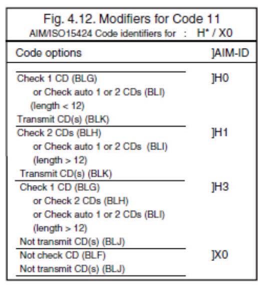
61 Options for Code 11 Code 11 is a variable length symbology with 1 or 2 optional check digits and non printable start/stop characters. If the data is 10 or less characters, one check digit is used. If the data is more then 10 characters, then 2 check digits are used. The following characters are supported: the digits 0 upto 9 the dash character '-' The first check digit is the modulo 11 sum of the weighted data character values. The second check digit is the modulo 11 sum of the weighted data character values including the first check digit. The check digits are not transmitted. For string format see figure Options for Code 11: disable check digit(s) automatic checking for 1 or 2 check digitsdepending of the number of data characters enable transmission of check digit(s) SET Not check CD BLF Check 1 CD BLG Check 2 CDs BLH Check auto 1 or 2 CDs Not transmit CD(s) BLI BLJ

62 Transmit CD(s) BLK Options for Korean Postal Authority code Korean Postal Authority code is a fixed length numeric symbology with a mandatory check digit. The check digit is not transmitted. For string format see figure Options for Korean Postal Authority code: transmit dash not transmit dash transmit CD not transmit CD Transmit dash: The dash character '-' (hex 2D) is printed between the 3rd and 4th digit SET Not transmit CD *- Transmit CD *+ Not transmit dash */ Transmit dash *

63 Options for Intelligent Mail Barcode Intelligent Mail Barcode is a symbology in four different states. It is formerly known as OneCode and is a variant of the 4-State Customer Barcode. The symbology is a height modulated and has a number of fixed lengths. For string format see figure Fixed data capacity: Numeric data: 20, 25, 29 or 31 characters Fixed data format and size: The data is built of several identifiers which follow each other in fixed order. Sizes are a predetermined amount of digits. Barcode identifier: 2 Service type identifier: 3 Mailer ID and Sequence number: maybe 6+9 digits or 9+6, always totalized to 15 Delivery point zip code: may be omitted (0), standard zip (5), zip+4 (9), zip+4 incl. delivery point digits (11) Checksum: An 11-bit CRC Frame Check Sequence is always calculated and is not transmitted. Encodable characters: digits 0 up to
64 Options for POSTNET POSTNET (Postal Numeric Encoding Technique) is a height modulated symbology with a number of fixed lengths. For string format see figure Fixed data capacity: Numeric data: 5 / 6 / 9 / 11 characters Additional data: 1 check digit Checkdigit: The start and stop pattern consist of a fixed single frame bar which is not unique inside the code. It is not transmitted. The check digit is calculated and transmitted with the barcode data. Encodable characters: digits 0 up to Options for GS1 Databar GS1 Databar is formerly known as RSS family including the RSS-14 group. Support for GS1 Databar options is reader dependent. Maximum data capacity: GS1 Databar and GS1 Databar Limited: Application Identifier "01" and 14 digits. GS1 Databar Expanded: 74 numeric or 41 alpha characters Checksums: The GS1 Databar family uses a mandatory checksum. GS1 Databar uses a modulo 79 checksum, GS1 Databar Limited uses a modulo 89 checksum GS1 Databar Expanded uses a modulo 211 checksum. The checksum is always calculated and is not transmitted
 Limited (refer to GS1 Databar Limited)")

65 Encodable characters: GS1 Databar and GS1 Databar Limited: digits 0 up to 9 GS1 Databar Expanded: subset of ISO 646: upper, lower case characters, digits, 20 punctuation characters and function character FNC1 The next GS1 Databar versions are supported Omnidirectional/Truncated/Stacked(refer to GS1 Databar) Limited (refer to GS1 Databar Limited) Expanded, Expanded stacked(refer to GS1 Databar Expanded) For string format see figure 3.39 or Options for GS1 Databar: transmission of CD transmission of Application Identifier Not transmit CD: Do not transmit the last character of GS1 Databar. SET Not transmit CD DM Transmit CD Not transmit Application Identifier Transmit Application Identifier DL DT DS

66 Options for Composite Codes CC-A is a modified MicroPDF417 version. CC-B is standard MicroPDF417. CC-C is standard PDF417. Maximum data capacity: CC-A: 56 characters CC-B: 338 characters CC-C: 2361 characters Symbol size: 1D part: see RSS and EAN codes Composite part: CC-A and CC-B same as MicroPDF417, CC-C same as PDF417 Error correction: 1D part: only error detection Composite part: Reed Solomon error correction Encodable characters: ASCII values ( ISO 646 ) ASCII values ( ISO , Latin alphabet No. 1, extended ASCII ) with ECI: many other character sets For string format of composite codes see figure 3.41 or 3.42 or Options for Composite codes: enable composite code ignore link flag output mode

67 For string format of composite codes see figure SET Not ignore composite link flag Ignore composite link flag Disable Composite on GS1-Databar Enable Composite on GS1-Databar As a single component, only 1D component is allowed As a single component, only 2D component is allowed As a single component, only 1D+2D component is allowed RQ RP BHF BHE BL0 BL1 BL2-62 -
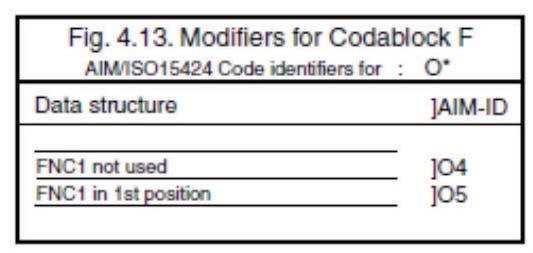
68 Options for Codablock F Codablock-F is variable size multi row (stacked) symbology based on Code 128. All features of Code 128 do apply for Codablock F. Maximum data capacity: text compaction = alphanumeric data: 2684characters numeric compaction = numeric data: 5368 Characters Symbol size: number of rows: 2 up to 44 number of columns: 1 up to 61 Error detection: Codablock has 1 additional character for the entire symbol. Codablock calculates 1 check digit that is not transmitted. Encodable characters: ASCII values ( ISO 646 ) 4 FNC values For string format see figure Options for DataMatrix Data Matrix is a variable size matrix symbology with selectable error correction levels. Maximum data capacity (ECC200): alphanumeric data: 2335 characters 8-bit data: 1556 characters numeric data: 3116 characters Symbol size: ECC : odd number of rows and columns, square shape. minimum: 9 * 9 modules, maximum: 49 * 49 modules
69 ECC200: even number of rows and columns, square or rectangular shape square: minimum 10 * 10, maximum 144 * 144 modules rectangular: minimum 8 * 18, maximum 16 * 48 modules Error correction: ECC : four levels of convolutional error correction, option for error detection only ECC200: Reed-Solomon error correction For new applications ECC200 is recommended. Additional features: extended Channel Interpretation (ECI, ECC200 only): support for different character sets and data interpretations structured append (ECC200 only): represent data in up to 16 Data Matrix symbols Support for these options is reader dependent. The supported character set and the maximum decodable number of characters are reader dependent. Encodable characters: ASCII values (ISO 646 ) ASCII values (ISO , Latin alphabet No. 1, extended ASCII ) with ECI: many other character sets For string format see figure Options for DataMatrix: Structured append time out: see chapter Read options
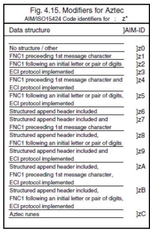
70 Options for Aztec Aztec code is a variable size matrix symbology with selectable error correction levels. Maximum data capacity: Standard Aztec: alphanumeric: 3067 characters numeric: 3832 characters byte: 1914 characters Aztec runes: values 000 up to 255 ( 3 digits ) Symbol size: Standard Aztec: minimum: 15 * 15 modules maximum: 151 * 151 modules Aztec runes: fixed: 11 * 11 modules Error correction: User selectable Reed-Solomon error correction levels from 5% to 95% of data region. Additional features: extended Channel Interpretation (ECI): support for different character sets and data interpretations structured append: represent data in up to 26 Aztec symbols mirror image: decode symbol in mirror reversal presentation Support for these options is reader dependent. The supported character set and the maximum decodable number of characters are reader dependent. Encodable characters: ASCII values ( ISO 646 ) ASCII values ( ISO , Latin alphabet No. 1, extended ASCII ) with ECI: many other character sets For string format see figure
71 Options for Aztec: structured append time out: see chapter Read options Options for Chinese Sensible code Chinese Sensible code is a matrix symbology with selectable error correction levels. The code allows 84 variable sized versions. Pattern: Each code is a square area comprised of a variable amount of nxn square symbols. A crossing alignment pattern is available in version 4 and its sequential versions. Al versions include four position detection patterns located on each corner. Maximum data capacity: The data capacity depends on the version. version 1: 205 characters sequential versions: increasing amount per version version 84: characters Symbol size: Chinese Sensible code has 84 versions, counting from version 1. Each following version has 2 more modules. minimum: version 1 = 23 * 23 modules sequentially: version 2 = 25 * 25, version 3 = 27 * 27, etc. maximum: version 84 = 189 * 189 modules Error correction: Four levels of Reed-Solomon error correction. Additional feature: Extended Channel Interpretation (ECI): support for Chinese character set, other different character sets and data interpretations. Support for this option is reader dependent. The supported character set and the maximum decodable number of characteristics is reader dependent. Encodable characters: numerical values 0-9 ASCII value ( ISO 646 ) binary byte ordinary Chinese characters ( GB Region, Double-byte, Four-byte ) with ECI: many other character sets

72 For string format see figure Options for QR Code QR code is a variable size matrix symbology with selectable error correction levels. Maximum data capacity: Model 1: alphanumeric data: 707 characters 8-bit data: 486 characters numeric data: 1167 characters kanji data: 299 characters Model 2: alphanumeric data: 4296 characters 8-bit data: 2953 characters numeric data: 7089 characters kanji data: 1817 characters Symbol size: Model 1: minimum: 21 * 21 modules maximum: 73 * 73 modules Model 2: minimum: 21 * 21 modules maximum: 177 * 177 modules Error correction: Four levels of Reed-Solomon error correction. Additional features: extended Channel Interpretation (ECI, model 2 only): support for different character sets and data interpretations. structured append: represent data in up to 16 QR Code symbols
73 Support for these options is reader dependent. The supported character set and the maximum decodable number of characters are reader dependent. Encodable characters: ASCII values ( ISO 646 ) ASCII values ( ISO , Latin alphabet No. 1, extended ASCII ) with ECI: many other character sets For string format see figure Options for QR code: structured append time out: see read mode options no further options supported Options for Micro QR Code Micro QR code is a compact version for the regular QR Code. Maximum data capacity: Model 1: numeric data: 5 characters Model 2: alphanumeric data: 6 characters numeric data: 10 characters Model 3: alphanumeric data: 11 characters 8-bit data: 9 characters numeric data: 18 characters kanji data: 6 characters Model 4: alphanumeric data: 21 characters 8-bit data: 15 characters numeric data: 35 characters kanji data: 9 characters
74 Symbol size: Model 1: 11 modules Model 2: 13 modules Model 3: 15 modules Model 4: 17 modules Error correction: Up to three levels of Reed-Solomon error correction for Model 4, no error correction for Model 1. Encodable characters: ASCII values (ISO 646) For string format see figure Options Micro QR Code no options supported Options for Maxicode Maxicode is a fixed size matrix symbology with selectable error correction levels. Maximum data capacity: alphanumeric data: 93 characters numeric data: 138 characters Symbol size: 28.14mm wide * 26.91mm high (including quiet zones) Error correction: 2 levels of Reed-Solomon error correction
75 Additional features: extended Channel Interpretation (ECI): support for different character sets and data interpretations structured append: represent data in up to 8 Maxicode symbols Support for these options is reader dependent. The supported character set and the maximum decodable number of characters, is reader dependent. Encodable characters: ASCII values (ISO 646) ASCII values (ISO , Latin alphabet No. 1, extended ASCII) with ECI: many other character sets For string format see figure Options for Maxicode: structured append time out: see read mode options no further options supported Options for PDF417 PDF417 is variable size multi row (stacked) symbology with selectable error correction levels. Maximum data capacity: text compaction: 1850 characters byte compaction: 1108 characters numeric compaction: 2710 characters Symbol size: number of row: 3 up to 90 number of columns: 1 up to 30 Error correction: 8 levels of error correction. Option for error detection only
76 Additional features: extended Channel Interpretation (ECI): support for different character sets and data interpretations macro PDF417: represent data in up to PDF417 symbols truncated PDF417: reduce some overhead to obtain smaller symbology size Support for these options is reader dependent. The supported character set and the maximum decodable number of characters, is reader dependent Encodable characters: ASCII values ( ISO 646 ) ASCII values ( ISO , Latin alphabet No. 1, extended ASCII ) for macro PDF417: many other character sets For string format see figure 3.52 Options for PDF417: macro PDF417 timeout ( same as Structured append time out ): see read mode options no further options available Options for MicroPDF417 MicroPDF417 is variable size multi row (stacked) symbology with fixed error correction levels. Maximum data capacity: text compaction: 250 characters byte compaction: 150 characters numeric compaction:366 characters Symbol size: number of row: 4 up to 44 number of columns: 1 up to 4 Error correction: Number of error correction codewords is dependent of symbol size and cannot be changed
77 Additional features: extended Channel Interpretation (ECI): support for different character sets and data interpretations macro MicroPDF417 ( structured append mode ): represent data in up to MicroPDF417 symbols Support for these options is reader dependent. The supported character set and the maximum decodable number of characters are reader dependent Encodable characters: ASCII values (ISO 646) ASCII values (ISO , Latin alphabet No. 1, extended ASCII) for macro MicroPDF417: many other character sets For string format see figure Options for MicroPDF417: macro MicroPDF417 timeout ( same as Structured append time out ): see read mode options no further options available

78 4. STRING OPTIONS This chapter describes the alterations which can be made to the format of the transmitted data string. Options available are: Case conversion conversion of bar code data The bar code data has the format as described in chapter Code Options. Set prefix and suffix transmission of a preamble (common prefix) transmission of a postamble (common suffix) transmission of a prefix transmission of a suffix The string format is transmitted as in figure The input entries are described in this chapter Case conversion The bar code data may be converted to either lower or upper case or the case may be exchanged. These options may be used if the user of a wedge has a preference to leave for instance the CAPSLOCK on or if the host requires upper case characters only. See figure
79 SET No case conversion YZ Convert to upper case YW Convert to lower case YX Exchange case YY 4.2. Set prefix and suffix A prefix and suffix of maximum 4 direct input entries each may be included in front and at the end of the string respectively. Bar code readers with an RS232 interface may be programmed with all 128 ASCII characters. Keyboard wedges may additionally be programmed with the special keys supported by the keyboard, e.g. function keys. Default settings are: - None, Suffix - ^M (CR) - None, Suffix return How to set a prefix or a suffix: To configure a prefix for example for Code-39 as C39: scan the following labels from this current chapter String Options : <SET> <Set prefix Code 39> <C> <3> <9> <:> <> Bar code readers which do not support a different prefix or suffix for each symbology have to make use of <ALL>
80 How to clear a prefix or suffix: To clear the suffix for example for Code 128 scan the following labels: <SET> <Set suffix Code 128> <> How to set a suffix for all symbologies: To configure for example the suffix <CR> for all symbologies scan the following labels: <SET> <Set suffix ALL> <^M (CR)> <> Note that this last example is for an RS232 interface. For a wedge interface a ^M (CR) results in the key combination <ctrl>m.if the direct input keyboard key <return> from this chapter is selected then the result is a <carriage return> or <Enter> key. See figure Preamble and postamble: A preamble is transmitted before the prefix and can contain up to 8 direct input characters. A postamble is transmitted after the suffix and can contain up to 8 direct input characters. A preamble and postamble will be transmitted for all symbologies. By default, the preamble and postamble is empty

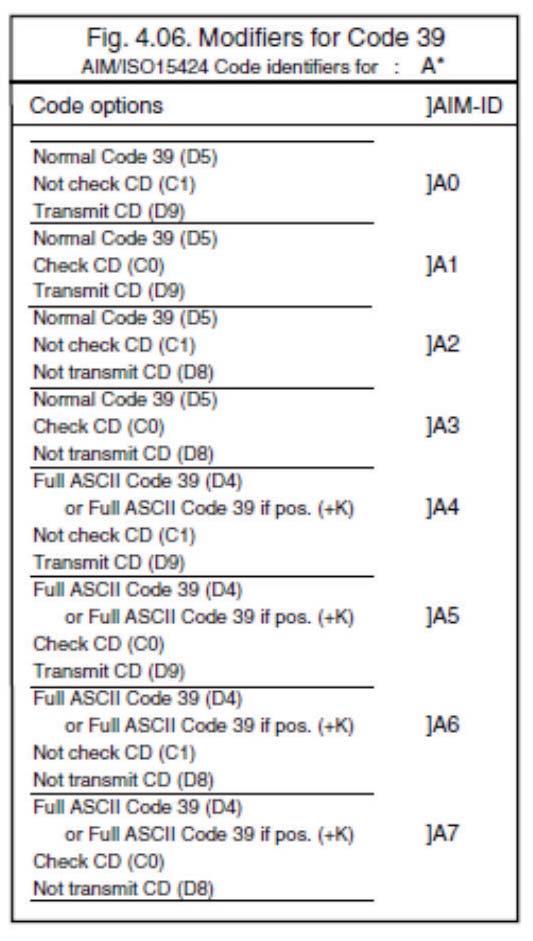
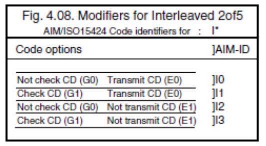
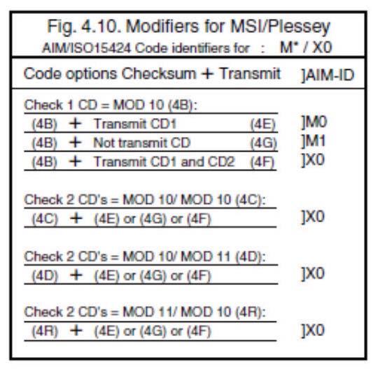
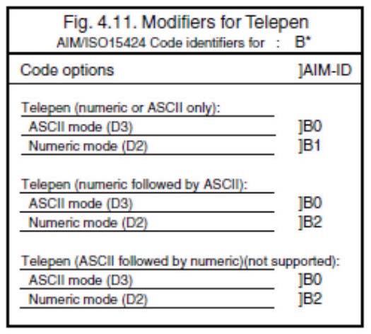
81 Code identification Opticon: A code identification and the code length may be included as a prefix or suffix. The direct input 'code identifier' provides a quick method of programming in addition to programming a separate prefix or suffix for each bar code type. See figure Code identification AIM/ISO: The Code identifier will be transmitted in the ISO format : ]cm, where: ] is ASCII value decimal 93 c is code character m is modifier character(s) For a detailed list of the modifier character 'm' and the AIM-ID s, refer to the ISO15424 standard. See figure

82 In case the modifier is an asterix (*), the value depends on the options of the symbology or on the configured Code options. For details refer to their own respective modifier tables. See figures 4.06 up to

83 - 78 -

84 - 79 -

85 - 80 -


86 - 81 -
87 Code length: The code length is transmitted as 2 digits, representing the decimal number of data characters transmitted, excluding prefix and suffix characters. For 2D bar codes the code length is transmitted as 6 digits. It is also possible to send for both 1D and 2D codes the length as 6 digits. These direct input characters count as 1 entry of the 4 permissible entries for a prefix or suffix. Example: If you want to configure the prefix <code identifier>:<code length>: scan the following labels: <SET> <Set prefix all> <Code identification> <:> <Code length> <:> <> If you want to use the code identifiers, but need another code identifier for Code 39, you scan the following labels: <SET> <Set prefix all> <Code identification> <:> <Set prefix Code 39> <$> <:> <> Set prefix SET All Codes RY UPC-A N1 UPC-A + add on M0 UPC-E N2-82 -
88 UPC-E + add on M1 EAN-13 N3 EAN-13 + add on M2 EAN-8 N4 EAN-8 + add on M3 Code 39 M4 Codabar M5 Industrial 2of5 M6 Interleaved 2of5 M7 S-Code MB Matrix 2of5 GL IATA I8 MSI/Plessey N0 Telepen L8 UK/Plessey MA Code 128 M9 Code 93 M8 Code 11 BLD
89 Korean Postal Authority *$ code Intelligent Mail Barcode D5I POSTNET D6D GS1-Databar OE Composite codes RR Codablock F D4S DataMatrix MD Aztec BF0 Chinese Sensible code D4N QR Code MK Maxicode ML PDF417 OC MicroPDF417 OD Clear all prefixes MG Preamble MZ
90 Set suffix SET All Codes RZ UPC-A N6 UPC-A + add on O0 UPC-E N7 UPC-E + add on O1 EAN-13 N8 EAN-13 + add on O2 EAN-8 N9 EAN-8 + add on O3 Code 39 O4 Codabar O5 Industrial 2of5 O6 Interleaved 2of5 O7-85 -
91 SET S-Code OB Matrix 2of5 GM IATA I9 MSI/Plessey N5 Telepen L9 UK/Plessey OA Code 128 O9 Code 93 O8 Code 11 BLE Korean Postal Authority code Intelligent Mail Barcode *% D5J POSTNET D6E GS1-Databar PQ
92 SET Composite codes RS Codablock F D4T DataMatrix PO Aztec BF1 Chinese Sensible code D4O QR Code PW Maxicode PX PDF417 PY MicroPDF417 PZ Clear all suffixes PR Postamble PS
93 Direct input keyboard keys SET F1 8J F2 8K F3 8L F4 8M F5 8N F6 8O F7 8P F8 8Q F9 8R F10 8S F11 8T F12 8U Backspace 9X
94 SET TAB 7H RETURN 7I Enter ( Numeric keypad ) 7Q ESC 7J Arrow down 7K Arrow up 7L Arrow right 7M Arrow left 7N <DEL> 7T <INSERT> VQ <HOME> VR <> VS Page up 7O
95 SET Page down 7P Left <Shift> 7U Left <Ctrl> 7W Left <Alt> 7Y Left <GUI> $8 Right <Shift> 7V Right <Ctrl> 7X Right <Alt> 7Z Right <GUI> $9 CAPSLOCK 9S
96 SET <SPACE> 5A! 5B 5C # 5D $ 5E % 5F & 5G ' 5H ( 5I ) 5J * 5K + 5L, 5M
97 SET - 5N. 5O / 5P : 6A ; 6B < 6C = 6D > 6E? 6G [ 7A \ 7B ] 7C
98 SET ^ 7D _ 7E 7F { 9T 9U } 9V ~ 9W
99 Direct input numeric SET 0 Q0 1 Q1 2 Q2 3 Q3 4 Q4 5 Q5 6 Q6 7 Q7 8 Q8 9 Q9-94 -
100 Direct input character SET A 0A B 0B C 0C D 0D E 0E F 0F G 0G H 0H I 0I J 0J K 0K L 0L M 0M
101 SET N 0N O 0O P 0P Q 0Q R 0R S 0S T 0T U 0U V 0V W 0W X 0X Y 0Y Z 0Z
102 Direct input lower case character SET a $A b $B c $C d $D e $E f $F g $G h $H i $I j $J k $K l $L m $M
103 SET n $N o $O p $P q $Q r $R s $S t $T u $U v $V w $W x $X y $Y z $Z
104 Direct input control character SET (NULL) 9G ^A (SOH) 1A ^B (STX) 1B ^C (ETX) 1C ^D (EOT) 1D ^E (ENQ) 1E ^F (ACK) 1F ^G (BEL) 1G ^H (BS) 1H ^I (HT) 1I ^J (LF) 1J ^K (VT) 1K ^L (FF) 1L
105 SET ^M (CR) 1M ^N (SO) 1N ^O (SI) 1O ^P (DLE) 1P ^Q (DC1) 1Q ^R (DC2) 1R ^S (DC3) 1S ^T (DC4) 1T ^U (NAK) 1U ^V (SYN) 1V ^W (ETB) 1W ^X (CAN) 1X ^Y (EM) 1Y
106 SET ^Z (SUB) 1Z ^[ (ESC) 9A ^\ (FS) 9B ^] (GS) 9C ^^ (RS) 9D ^_ (US) 9E DEL (ASCII 127) 9F Direct input code id/length SET Code identification $2 Code identification ISO / AIM Code length (1D = 2 digits, 2D = 6 digits) Code length (1D and 2D = 6 digits) $1 $3 $
107 5. READ OPTIONS This chapter allows to set the read mode, trigger type, redundancy and illumination Read mode options The following read modes are available: Single read: When a bar code has been decoded, the reader will be turned OFF. The reader must be triggered again to read another label. This option and 'Disable trigger' can not be programmed at the same time. Multiple read: When a bar code has been decoded, the reader will stay ON for a time as set by 'Read time options' or indefinitely if the trigger switch has been disabled. The same label can only be decoded again after the label has not been detected for a number of scans. Continuous read: The reader will produce as much data as it can decode regardless whether it is the same or not. This mode is mainly used for demonstration and diagnosis. Disable trigger: This is applicable to readers which have a trigger switch. When this option is selected, the reader will stay ON all the time. Note: Selecting this option for a laser reader means that the laser diode is ON continuously, which may reduce the lifetime of this component. Also local legislation may require that the trigger switch is always enabled. Therefore it is recommended not to disable the trigger switch for laser readers. Add-on wait mode: Used if UPC/EAN with add-on is enabled. The reader searches within the selected time for a valid add-on code. If a valid add-on code is found, the reader transmits the data immediately. If nothing is found behind the code, the reader will transmit the data without add-on. If something is found behind the code, the reader ignored the code in case it is not a valid add-on
108 Trigger repeat: This option makes it easier to select a single bar code from a sheet filled with bar codes. If the trigger switch is pressed once, the laser beam is on during the configured read time. The laser beam can now be moved to the required bar code. If the trigger switch is pressed again, the bar code is decoded and transmitted. If the read time expires, the laser switches off and the trigger sequence should be repeated. If the read time is set to 0, then if the trigger switch is pressed, the laser is on, but does not accept bar codes. As soon the trigger switch is released, the barcode is decoded and transmitted. Support for this option is reader dependent. Structured append time out: When a bar code consists of multiple physical bar codes, this time out value is used. The next bar code must be read before this time out is expired. The time out value is between 1 and 255 seconds. This value can be configured by reading 1 up to 3 direct input numeric characters from chapter: String options. Default the structured append time out is set to 30 seconds
109 SET Single read S0 Multiple read Continuous read S2 Disable trigger S7 Enable trigger S8 Add-on wait mode disabled XA Add-on wait mode 0.25 sec. XB Add-on wait mode 0.50 sec. Add-on wait mode 0.75 sec. XD Disable trigger repeat Enable trigger repeat /M

110 Multiple read reset time This option can be used in conjunction with multiple read mode. for Laser and CCD readers, it sets the time that the reader should be pointed away from the label before it can decode the same label again for Image readers, it sets the number of frames that the reader should be pointed away from the label before it can decode the same label again Indefinitely means that the next bar code must always be different, during the time the bar code reader is triggered. For the image reader the multiple reset time is not measured in ms, but in frames. The duration of each frame is variable, and is dependent of the captured image. See figure SET 50ms AH 100ms AI 200ms AJ 300ms AK 400ms AL 500ms AM 600ms AN Indefinitely AG
111 Quiet zone options With this option the reader can decode bar codes that have smaller start and/or end margins than specified for the symbology. Be careful when using this option. It may increase the possibility of partial reads and ghost reads. Do not use smaller margin checks then necessary. If possible replace the bar code labels by ones that have correct start and end margins. SET No margin check YN Margin check 1/7 nominal YO Margin check 2/7 nominal YP Margin check 3/7 nominal YQ Margin check 4/7 nominal YR Margin check 5/7 nominal YS Margin check 6/7 nominal YT Margin check normal YU Auto trigger options These options are used to activate the auto trigger option of the reader. This is only supported for reader equipped with the auto trigger option. Disable auto trigger: The auto trigger function is not activated. Enable auto trigger: The reader will be triggered if it detects changes in brightness
112 SET Disable auto trigger +F Enable auto trigger +I Detection Mode There are three methods for detecting a target code. (1) Green aiming detection When a target code falls within the aiming range while the green aiming light is emitted, the target is detected. It is recommended to use this mode indoors because the detectability is reduced in an environment of higher illuminance levels than indoor s. (2) Red illumination detection When a target code falls within the range of the field of view while the red illumination light is emitted, the target is detected. This mode can be used in a lighted environment. (3) No illumination detection A target code is detected without illumination light. The power consumption can be reduced, but the response of detection will also be reduced. Ambient light is used for detection in this mode, so this cannot be used in a dark place while it can be used in a lighted environment. SET Green aiming detection DDG Red illumination detection DDH No illumination detection DDI
113 Auto Trigger Condition The detection sensitivity can be adjusted. The sensitivity varies with ambient environment and the adjustment may be needed. SET Sensitive XMF Normal XMH Insensitive XMJ 5.2. Read time options The length of the period that the reader is ON after the trigger switch is pressed, or (in multiple or continuous read mode) after a label has been read. Selecting a read time of 0 means that the reader will stay ON as long as the trigger switch is being pressed. Selecting a read time for readers without a trigger switch, or when the trigger switch is disabled, does not have any effect. SET 0 seconds Y0 1 second Y1 2 seconds Y2 3 seconds Y3 4 seconds Y4 5 seconds Y5 6 seconds Y
114 7 seconds Y7 8 seconds Y8 9 seconds Y9 Read time * 10 YL Indefinitely YM 5.3. Redundancy This is the number of times that a label must be correctly decoded before it is transmitted. Selecting a higher redundancy count makes reading slower, but it reduces the probability of reading errors, especially when labels of poor definition are used. SET Read 1 time, redundancy = 0 X0 Read 2 times, redundancy = 1 X1 Read 3 times, redundancy = 2 X2 Read 4 times, redundancy = 3 X Positive and negative bar codes Usually bar codes are printed black on white, but sometimes white on black. These labels are called positive and negative respectively. In case the 'negative bar codes' option has been selected, positive labels may not be decoded anymore or with difficulty. This also applies to menu labels. To enable the reader to read positive labels again, a number of negative menu labels have been included
115 SET Positive bar codes V2 Negative bar codes V3 Positive and negative bar codes V4 Positive bar codes V2 Positive and negative bar codes V4 SET / ZZ 5.5. Floodlight and aiming options The floodlight and aiming options affect the light source that illuminates the area of the bar code symbol. The floodlight illuminates the full area during image capturing. When the scannable area consists of a highly reflecting surface the floodlight might need to be disabled to prevent over-exposure. If an aiming light is available, the bar code reader can generate an aiming pattern to help the user to target at the bar code symbol. The aiming pattern will only be visible between two image captures. The aiming pattern will be off when the floodlight is on. Disable floodlight: The option disable floodlight does not illuminate the area of the bar code symbol during image capturing. Alternating floodlight: The option alternating floodlight switches by turn between enabled and disabled floodlight. Prevent specular reflection Only when specular reflection of LED illumination occurs, the reading is performed
116 with illumination turned off. SET Disable floodlight D3A Enable floodlight D39 Alternating floodlight D3B Prevent specular reflection D3Q 5.6. Prevention of flicker When there is not target to be read, flicker occurs because of the LED illumination, and this flicker can be prevented with setting. However, by enabling the setting, codes on LCD screen will be difficult to be read. SET Enable LCD display reading D3J LED illumination flicker prevention D3I
117 5.7. LED aiming Green LED floodlight used for aiming can be set to enable / disable. The brightness is also configurable. SET Enable LED aiming D3D Disable LED aiming D3E Brightness High DDD Brightness Standard DDE Brightness Low DDF

118 6. INDICATOR OPTIONS This chapter describes the options for the Buzzer and Good Read LED Buzzer settings These options determine the buzzer type, tone, duration and loudness. The buzzer tone and loudness are reader dependent due to different buzzer types. Buzzer type: The buzzer may be disabled or enabled as either a hardware or software buzzer. Not all readers support both a hardware and software buzzer. Buzzer tone: If a software buzzer is used, the buzzer tone may be selected as shown in figure Buzzer duration and loudness: If a software buzzer is used, a buzzer duration of 50, 100, 200 or 400 msec. may be selected. The loudness can be adjusted in four different steps. Buzzer before transmission: The good read buzzer will be activated after decoding the bar code, but before transmission. During the transmission the buzzer sequence will be completed. The good read buzzer will be activated after transmission. Enable startup buzzer: When this options is selected, the reader will generate a single good read buzzer to indicate the reader is ready after the reader is supplied with power
119 Disable startup buzzer: When this options is selected, the reader will not sound the buzzer after the reader is supplied with power. SET Disable buzzer W0 Enable buzzer W8 Single tone buzzer W1 High - low buzzer W2 Low - high buzzer W3 Buzzer duration 50 msec W7 Buzzer duration 100msec W4 Buzzer duration 200 msec W5 Buzzer duration 400 msec W6 Buzzer loudness: Maximum T0 Buzzer loudness: Loud T1 Buzzer loudness: Normal T2 Buzzer loudness: Minimum T3 Buzzer before transmission VY Buzzer after transmission VZ
120 Disable startup buzzer GD Enable startup buzzer GC 6.2. Good read LED The Good Read LED can be disabled or set for several durations. SET Disable indicator T4 Indicator duration: 0.2 s T5 Indicator duration: 0.4 s T6 Indicator duration: 0.8 s T
121 7. MISCELLANEOUS 7.1. Diagnostics The options in this part are primarily intended for diagnostic purposes. The following options are available: Transmit software version: The software version is transmitted. Transmit settings: The reader settings are transmitted as a string of hexadecimal numbers. Transmit ASCII printable string: The printable ASCII characters Hex 20 up to Hex 7F are transmitted. Transmit ASCII control string: The non-printable ASCII control characters Hex 00 up to Hex 1F are transmitted. SET Transmit software version Z1 Transmit settings Z3 Transmit ASCII printable string ZA Transmit ASCII control string YV
122 7.2. Serial configuration support Disable configuring via RS232: The reader ignores all configuration commands from the RS232 port. The trigger and buzzer commands are still accepted. Enable configuring via RS232: The reader accepts all configuration commands from the RS232 port. Disable trigger via RS232: The reader ignores the trigger command, <Z> (Hex 5A), via the RS232 port. Enable trigger via RS232: The reader accepts the trigger command via the RS232 port. Disable buzzer via RS232: The reader ignores the buzzer command via the RS232 port. Enable buzzer via RS232: The reader accepts the buzzer command, <B> (Hex 42) for the good read buzzer and <E> (Hex 45) for the error buzzer, via the RS232 port. Disable Good read LED via RS232: The reader ignores the good read LED command via the RS232 port. Enable Good read LED via RS232: The reader accepts the good read LED command, <L>(Hex 4C), via the RS232 port. Disable ACK/NAK for RS232 commands: The reader does not transmit <ACK> nor <NAK> when a command is received. Enable ACK/NAK for RS232 commands: The reader transmits an <ACK> (Hex 06) after each valid RS232 command and a <NAK> (Hex 15) after each invalid RS232 command. Error message - No label: Following this menu label a maximum of 4 direct input characters may be read. These characters will be transmitted if during the read time of the reader no label was detected. This function is only available on readers where the trigger is enabled. If no direct input character is read following the command, the error message is disabled. The function may be combined with 'Error message - No decode'. Error message - No decode: Following this menu label a maximum of 4 direct input characters may be read. These

123 characters will be transmitted if during the read time of the reader a label was detected, but nothing could be decoded. This function is only available on readers where the trigger is enabled. If no direct input character is read following the command, the error message is disabled. The function may be combined with 'Error message - No label'. Example: The following two examples will set the messages 'NL<CR>' and 'ND<CR>' for No label and No decode respectively. The two examples may both be active at the same time. See figure
KD-3500ZB. Wireless Area-Imaging Scanner Configuration guide
 KD3500ZB Wireless AreaImaging Scanner Configuration guide bar code configuration Ui TABLE OF CONTENTS 1. Introduction...U1 2. Defaults...U3 3. Code options... U5 3.1. Setting of readable codes... U6 3.1.1.
Set up your personal configuration. Universal menu book. bar code configuration and commands manual
 Set up your personal configuration Universal menu book bar code configuration and commands manual Set up your personal configuration Universal menu book bar code configuration and commands manual revised
MP720 Presentation Imager
 MP720 Presentation Imager User Manual Version: MP720_UM_EN_V1.1.3 Notice Ensure that the optional DC adapter works at +5V, especially for the RS-232 interface cable. 1. All software, including firmware,
Product Engineering Specification Scan Utility
 Product Engineering Specification Scan Utility Overview: 1. What is Scan Utility? Scan Utility provides a user interface that communicates with the scanner. It can set up the scanner, download the scanner
Xi2000-BT Series Configuration Guide
 U.S. Default Settings Sequence Reset Scanner Xi2000-BT Series Configuration Guide Auto-Sense Mode ON UPC-A Convert to EAN-13 OFF UPC-E Lead Zero ON Save Changes POS-X, Inc. 2130 Grant St. Bellingham, WA
MP168 Screen Barcode Image Platform
 MP168 Screen Barcode Image Platform User Manual Version: MP168_UM_EN_V1.1.1 Notice Ensure that the optional DC adapter works at + 5 VDC, especially for the RS-232 interface cable. 1. All software, including
MD60xx Image Barcode Scanner
 MD60xx Image Barcode Scanner User Manual Version: MD60xx_UM_EN_V1.1.2 Notice Ensure that the optional DC adapter works at +5V, especially for the RS-232 interface cable. 1. All software, including firmware,
USER MANUAL. ZKB200 Handheld Image Scanner. Version:1.0 Date: April, 2018
 USER MANUAL ZKB200 Handheld Image Scanner Version:1.0 Date: April, 2018 Notice Ensure that the optional DC adapter works at +5 VDC, especially for the RS-232 interface cable. 1. All software, including
El5220. Image Platform. User Manual
 El5220 Image Platform User Manual Version: El5220 _UM_EN_V1.1.3 NOTICE Ensure that the optional DC adapter works at +5V, especially for the RS-232 interface cable. 1. All software, including firmware,
510-2d Complete Configuration Guide Worth Data Inc. 05/2010
 510-2d Complete Configuration Guide Worth Data Inc. 05/2010 i User Preferences Table 5-1. User Preferences Default Table Parameter Parameter Number Default Page Number User Preferences Set Default Parameter
User s Manual. Xi3000 Scanner. Table of Contents
 Xi3000 Scanner User s Manual Table of Contents Restore Default Settings... 1 Exit Setup without Changes... 1 Configure Through RS232... 1 List Setting... 1 Buzzer Settings... 2 Reading Redundancy Setting...
NCR Realscan 7837 High-Performance Scanners. User s Guide Issue A
 NCR Realscan 7837 High-Performance Scanners User s Guide 497-0427357 Issue A Table of Contents Chapter 1 - Getting Started About This Manual... 1-1 Unpacking the Scanner... 1-2 RealScan 7837 High-Performance
Introduction. Installation- Keyboard Wedge
 Introduction Installation- Keyboard Wedge 1) First of all, you must switch off power for the terminal/computer. 2) Disconnect the keyboard cable from the back of the terminal/computer. 3) Connect the appropriate
MP80xx Image Platform
 MP80xx Image Platform User Manual Version: MP80xx_UM_EN_V1.1.3 NOTICE Warning: Ensure that the optional DC adapter works at +5V, especially for the RS-232 interface cable. 1. All software, including firmware,
MD65xx Image Barcode Scanner
 MD65xx Image Barcode Scanner User Manual Version: MD65xx_UM_EN_V1.1.1 Warning: Ensure that the optional DC adapter works at +5V, especially for the RS-232 interface cable. NOTICE: 1. All software, including
User s Manual WARNING CIPHER 1000 CCD SERIES
 CIPHER 1000 CCD SERIES User s Manual WARNING This equipment has been tested and found to comply with the limits for a Class A digital device, pursuant to Part 15 of FCC Rules. These limits are designed
2D Barcode Reader User Guide V 1.2.1
 2D Barcode Reader User Guide V 1.2.1 Table of Contents 1 Getting Started... 3 1.1 About This Guide... 3 1.2 Barcode Scanning... 3 1.3 Factory Defaults... 3 1.4 Firmware Version Number... 3 2 Communication
BARCODE SCANNER. Configuration Guide - 1 -
 BARCODE SCANNER Configuration Guide - 1 - Table of Contents Chapter 1 System Information 1.1 About this manual 3 1.2 How to set up the parameter 3 1.3 How to set up the parameter - II 4 Chapter 2 System
NC-1200 BARCODE SCANNER. Configuration Guide - 1 -
 NC-1200 BARCODE SCANNER Configuration Guide - 1 - Table of Contents Chapter 1 System Information 1.1 About this manual 3 1.2 How to set up the parameter-i 3 1.3 How to set up the parameter II 4 1.4 Resetting
MD22xx Barcode Scanner
 MD22xx Barcode Scanner User Manual Version: MD2250_UM_EN_V3.2.18 NOTICE Ensure that the optional DC adapter works at +5 VDC, especially for the RS-232 interface cable. 1. All software, including firmware,
MD22xx Barcode Scanner
 MD22xx Barcode Scanner User Manual Version: MD22xx_UM_EN_V3.2.17 NOTICE Ensure that the optional DC adapter works at +5 VDC, especially for the RS-232 interface cable. 1. All software, including firmware,
MK D Imager Barcode Scanner Configuration Guide
 MK-5500 2D Imager Barcode Scanner Configuration Guide V1.4 Table of Contents 1 Getting Started... 3 1.1 About This Guide... 3 1.2 Barcode Scanning... 3 1.3 Factory Defaults... 3 2 Communication Interfaces...
Area Imager Bar Code Scanner 2 D C O N F I G U R A T I O N G U I D E
 Area Imager Bar Code Scanner 2 D C O N F I G U R A T I O N G U I D E Copyright @ 2017 This manual is copyrighted, with all right reserved. Under the copyright laws, this manual may not, in whole or in
FD-011WU. 2D Barcode Reader User Guide V1.6CC
 FD-011WU 2D Barcode Reader User Guide V1.6CC Table of Contents 1 Getting Started... 1 1.1 Factory Defaults... 1 2 Communication Interfaces...2 2.1 TTL-232 Interface... 2 2.2 Baud Rate... 3 2.3 Data Bit
Configuration Manual PULSAR C CCD SCANNER. Table of Contents
 Table of Contents PULSAR C CCD SCANNER Configuration Manual Metrologic Instruments GmbH Dornier Strasse 2 82178 Puchheim Germany Tel +49 89 890190 Fax +49 89 89019200 www.europe.metrologic.com Metrologic
Code Reader 1000/1400/8000 Configuration Guide
 Code Reader 1000/1400/8000 Configuration Guide Code Reader 1000 Code Reader 1400 Code Reader 8000 1 Table of Contents USB Settings USB Keyboard Mode...6 (A1) USB Downloader Mode...6 (A2) USB Virtual COM
CR2300 CR2600 CR3600 (DPM)
") CONFIGURATION GUIDE ENGLISH CR2300 CR2600 CR3600 (DPM) CONFIGURATION GUIDE: VERSION 12 SUPPORTED FIRMWARE: READERS 0956+, MODEM 2000+ RELEASE DATE: SEPTEMBER 2014 www.codecorp.com User Manuals YouTube.com/codecorporation
CONFIGURATION GUIDE ENGLISH CR2300 CR2600 CR3600 (DPM) CONFIGURATION GUIDE: VERSION 12 SUPPORTED FIRMWARE: READERS 0956+, MODEM 2000+ RELEASE DATE: SEPTEMBER 2014 www.codecorp.com User Manuals YouTube.com/codecorporation
marson MT8200S 2D Handheld Scanner User Manual V / 6 / 25 - I -
 marson MT8200S 2D Handheld Scanner User Manual V1.1 2018 / 6 / 25 - I - Table of Contents 1 Gettting Started...1 1.1 Introduction...1 1.2 Configuring MT8200S...1 1.2.1 Barcode Configurability...1 1.2.2
User s Manual 131 Tiny III Decoder
 User s Manual 131 Tiny III Decoder Document Number : 131-0114 Release Date : Mar 16, 1998 1998, SYNTECH INFORMATION Co., Ltd.. All rights reserved. CipherLab is a registered trademark of SYNTECH INFORMATION
MDI Serial Interface Specifications Manual. Auto Focus 2D Scan Engine
 Auto Focus 2D Scan Engine MDI-2300 This document provides the configuration specifications for the auto-focus imager scan engine, MDI-2300. Serial Interface Specifications Manual All information subject
Wireless Pocket 2D Imager Scanner
 Wireless Pocket 2D Imager Scanner - MS920P - User's Manual Version 1.0 2014 unitech Electronics Co., Ltd. All rights reserved. unitech is a registered trademark of unitech Electronics Co., Ltd. Table
2D Scan Engine Confguration Guide. 2D Barcode Scanner Configration Guide
 2D Barcode Scanner Configration Guide 1 Table of Contents USB Settings USB Keyboard Mode...6 (A1) USB Downloader Mode...6 (A2) USB Virtual COM One Way Mode...6 (A3) USB Native Two Way Mode...6 (A4) USB
Nuscan 3200 Optical Laser Barcode Scanner
 Nuscan 3200 Optical Laser Barcode Scanner Programming Manual FCC Compliance This equipment has been tested and found to comply with the limits for a Class A digital device, pursuant to Part 15 of the FCC
Table of Contents. Introduction Installation Pin Assignments Method of Programming Setup Commands... 9
 Table of Contents Introduction... 3 Installation... 4 Pin Assignments... 5 Method of Programming... 7 Setup Commands... 9 Interface selection... 10 Reading Mode... 11 RS 232 Communication Parameters...
COPYRIGHT 2009,SCSC. Manual P/No: SCCM - 80S-01A Released Date: Oct 31, 2009
 To begin the configuration procedures Thank you for purchasing the scanner. Inside each packaging box, you may find the scanner, the interface cable and user's fuide. Configuration manual might be optional
Code Reader 1000/1400/8000 Configuration Guide
 Code Reader 1000/1400/8000 Configuration Guide Code Reader 1000 Code Reader 1400 Code Reader 8000 1 Table of Contents USB Settings USB Keyboard Mode...6 (A1) USB Downloader Mode...6 (A2) USB Virtual COM
Table of Contents Sleep Settings How to Configure the Scanner. 7 Chapter 2 System Setup
 Table of Contents Chapter 1 System Information 1.1 Setup Scanner with PC 1.2 Setup Scanner with Mobile Device 1.3 Configure ios On-Screen Keyboard 1.4 Memory Mode 3 4 4 5 1.5 Sleep Settings 6 1.6 How to
ScanManager for Scanner Configuration
 ScanManager for Scanner Configuration For 1 Series Barcode Scanners: 1000, 1090+, 1100, 1105, 1166, 1200 & 1266 Version 3.01 Copyright 2006~2011 CIPHERLAB CO., LTD. All rights reserved The software contains
ES4200 Embedded Laser Barcode Scanner
 ES4200 Embedded Laser Barcode Scanner User Manual Version: ES4200_UM_EN_V1.1.7 Notice Make sure you carefully read the following information to ensure that your barcode scanner is able to perform at the
XB-8200 Hand Free Area Image Scanner Configuration Guide
 XB-8200 Hand Free Area Image Scanner Configuration Guide V1.3 Table of Contents Chapter 1 General Description... 1 Chapter 2 Introduction... 2 Chapter 3 User Preferences... 4 RETURN TO DEFAULT... 4 PARAMETER
If you want to have other configurations please refer to below programming barcodes. Check Scanner Version
 NT-1228BL V18.7.12 Quick Setup Guide This model can work both via USB cable or via bluetooth. Connection Mode Working via USB cable Get Started: Connect scanner with your device via USB cable. If you use
Configuration Guide. Code Reader C005435_02_CR1000_CR8000_ConfigurationGuide 1
 Code Reader 1000/8000 Configuration Guide Code Reader 1000 Code Reader 8000 C005435_02_CR1000_CR8000_ConfigurationGuide 1 Table of Contents USB Settings USB Keyboard Mode...6 (A1) USB Downloader Mode...6
GS500 2D Area-Imaging Scanner. User Manual
 GS500 2D Area-Imaging Scanner User Manual Table of Contents Table Of Contents... 1 Chapter 1 Getting Started... 6 About This Guide... 6 Barcode Scanning... 6 Barcode Programming... 6 Factory Defaults...
Installation- Keyboard Wedge
 0 Introduction Installation- Keyboard Wedge 1) First of all, you must switch off power for the terminal/computer. 2) Disconnect the keyboard cable from the back of the terminal/computer and connect to
Barcode BC-29. Decoder & Platform. Programming Manual
 Barcode BC-29 Decoder & Platform Programming Manual CONTENTS Getting Started...2 Setting Procedures...3 Setting Flow Chart......4 Group 1 : Multi Validation....5 Group 2 : Hold Time...6 Group 3: Scan Mode
Area Imager Bar Code Scanner
 Area Imager Bar Code Scanner 2 D C O N F I G U R A T I O N G U I D E SYMBOLOGY PROGRAMMING for POCKET SCANNERS Copyright @ 2017 This manual is copyrighted, with all right reserved. Under the copyright
ZB-8150/ZB-8110/ZB-8210 CCD BARCODE SCANNER. User s Manual. ZBA Inc 249 Homestead Rd Unit 12 Hillsborough NJ 08844
 ZB-8150/ZB-8110/ZB-8210 CCD BARCODE SCANNER User s Manual ZBA Inc 249 Homestead Rd Unit 12 Hillsborough NJ 08844 Phone: 908-359-2070 Fax: 908-359-1272 Web: http://www.zbausa.com/ Installation: Keyboard
2 D C O N F I G U R A T I O N G U I D E B T S C A N N E R
 Area Imager Bar Code Scanner 2 D C O N F I G U R A T I O N G U I D E B T S C A N N E R Copyright @ 2018 This manual is copyrighted, with all right reserved. Under the copyright laws, this manual may not,
Setup Procedures 2 Batch Setup 3. Bar Code Setup Menu 5. 1 Device Selection and Default. 2 Beep and Delay Keyboard Wedge..
 Contents Setup Procedures 2 Batch Setup 3 Bar Code Setup Menu 5 1 Device Selection and Default 5 2 Beep and Delay... 7 3 Keyboard Wedge.. 9 4 RS232 Serial Setting.... 11 5 Scanner.. 13 7 Symbologies(I):
1504 Barcode Scanner. Setup barcodes included. Version 1.00
 1504 Barcode Scanner Setup barcodes included. Version 1.00 Copyright 2011 CIPHERLAB CO., LTD. All rights reserved The software contains proprietary information of CIPHERLAB CO., LTD.; it is provided under
User s Manual WARNING. WWS800/850 Bluetooth Wireless Scanners
 WWS800/850 Bluetooth Wireless Scanners User s Manual WARNING This equipment has been tested and found to comply with the limits for a Class A digital device, pursuant to Part 15 of FCC Rules. These limits
MDI-3000 MDI Serial Interface Specifications Manual. 2D Scan Engine MDI-3x00-Serial
 2D Scan Engine MDI-3x00-Serial MDI-3000 MDI-3100 This document provides the configuration specifications for the imager scan engine, MDI-3x00 Serial Interface Specifications Manual All information subject
User's Manual CIPHER 1022 SERIES
 User's CIPHER 1022 SERIES Document Number : 1022-52 Ver. 1.520 Release Date : Apr 22, 1996 1996, SYNTECH INFORMATION Co., Ltd.. All rights reserved. CipherLab is a registered trademark of SYNTECH INFORMATION
SIMATIC Ident Handheld reading systems SIMATIC MV325 Configuration guide Compact User Manual
 SIMATIC Ident Handheld reading systems Compact User Manual Legal information Warning notice system This manual contains notices you have to observe in order to ensure your personal safety, as well as to
Code Interleaved 2 of 5. Plessey Minimum And Plessey Maximum Length. Field Size/Char. Enabled.
 Chapter 5: Configuration Decoded (HHP) Plessey Minimum And Plessey Maximum Length These parameters apply to Plessey bar codes.the length of a code refers to the number of characters (i.e., human readable
Laser Barcode Scanner ARP Nr User s Manual
 Laser Barcode Scanner ARP Nr. 853782 User s Manual FCC Compliance This equipment has been tested and found to comply with the limits for a Class B digital device, pursuant to Part 15 of the FCC Rules.
Code Reader 900FD Configuration Guide
 Code Reader 900FD Configuration Guide 1 Table of Contents Reader Settings Save Settings...5 (A1) Reader ID and Firmware Version... 5 (A2) Feedback Settings Beep On...5 (A3) Beep Off...5 (A4) Targeting
PureScan - ML1. Configuration Guide. Wireless Linear Imager Wireless Laser scanner - 1 -
 PureScan - ML1 Wireless Linear Imager Wireless Laser scanner Configuration Guide - 1 - Table of Contents Chapter 1 System Information 1.1 About this manual 3 1.2 How to set up the parameter 3 Chapter 2
C O N F I G U R A T I O N G U I D E
 C O N F I G U R A T I O N G U I D E Copyright @ 2013, This manual is copyrighted, with all right reserved. Under the copyright laws, this manual may not, in whole or in part, be copied, photocopied, reproduced,
Code Reader 2300/2600/3600/CR3600 DPM Configuration Guide
 Code Reader 2300/2600/3600/CR3600 DPM Configuration Guide 1 Table of Contents Modem Settings (for use with the Charging Station with an Embedded CodeXML Modem or the external CodeXML M3 Modem when paired
User Manual. PULSAR C CCD Hand-Held Scanner WARNING
 WARNING PULSAR C CCD Hand-Held Scanner User Manual This equipment has been tested and found to comply with the limits for a Class A digital device, pursuant to Part 15 of FCC Rules. These limits are designed
User s Guide. Linear Imager
 User s Guide 3200 Linear Imager Disclaimer Hand Held Products, Inc. ( Hand Held Products ) reserves the right to make changes in specifications and other information contained in this document without
IPDA014-2D. Embedded 2D Barcode Scan Engine. User Guide
 IPDA014-2D Embedded 2D Barcode Scan Engine User Guide 1 Table Of Contents Chapter 1 Getting Started...8 Introduction...8 About This Guide...8 Barcode Scanning...9 Barcode Programming...9 Factory Defaults...9
User s Manual WARNING. CIPHER 1160/1260 Bluetooth Wireless Scanner
 CIPHER 1160/1260 Bluetooth Wireless Scanner User s Manual WARNING This equipment has been tested and found to comply with the limits for a Class A digital device, pursuant to Part 15 of FCC Rules. These
RT209 OEM 2d Scan Engine User Guide
 RT209 OEM 2d Scan Engine User Guide Table Of Contents Chapter 1 Getting Started... 1 About This Guide... 1 Connecting EVK to PC... 1 Barcode Scanning... 1 Barcode Programming... 1 Custom Defaults... 3
MD5 Series Barcode Scanner
 MD5 Series Barcode Scanner User Manual Version: MD5_UM_EN_V1.1.7 Warning: Ensure that the optional DC adapter works at +5V, especially for the RS-232 interface cable. NOTICE: 1. All software, including
User s Manual. LGP Series Handheld CCD Scanner. 25-ULGPMU01-01 November Keyboard Wedge Interface USB Interface RS232 Interface
 User s Manual LGP Series Handheld CCD Scanner 25-ULGPMU01-01 November 2007 Keyboard Wedge Interface USB Interface RS232 Interface 8 Olympic Drive Orangeburg, NY 10962 Tel 845.365.0090 Fax 845.365.1251
If you want to do other configurations please refer to below programming barcodes.
 NT-1202 Quick Setup Guide This is 1D&2D plug and play model if you use a US keyboard. If you use other type of keyboard, plug the USB cable on your device, setup keyboard language before you use it. (refer
RT206 User Guide. RT206 OEM 2d Scan Engine User Guide
 RT206 OEM 2d Scan Engine User Guide Table Of Contents Chapter 1 Getting Started... 1 About This Guide... 1 Connecting EVK to PC... 1 Barcode Programming... 2 Factory Defaults... 2 Custom Defaults... 3
Manual de Programación
 Manual de Programación SM2410, SM2410B, SM2420 y SM2430 ESPECIFICACIONES SUJETAS A CAMBIO SIN PREVIO AVISO. Enter/Exit Programming Mode (This barcode is also found at page 8.) IMPORTANT NOTICE Every effort
530-2D-USB 2D Scanner High Speed Imaging USB Bar Code Scanner
 530-2D-USB 2D Scanner High Speed Imaging USB Bar Code Scanner Worth Data USB 2D Bar Code Scanner - Scan 1D & 2D Matrix Bar codes www.worthdata.com Owner s Manual Warning: This equipment generates, uses
User s Manual. Xi3000 Bluetooth Scanner WARNING
 Xi3000 Bluetooth Scanner WARNING This equipment has been tested and found to comply with the limits for a Class A digital device, pursuant to Part 15 of FCC Rules. These limits are designed to provide
Disclaimer. Please read through the manual carefully before using the product and operate it
 ONEBRAND,ONESOLUTI ON 2D Handhel dbar codescanner UserManual Disclaimer Please read through the manual carefully before using the product and operate it according to the manual. It is advised that you
If you want to do other configurations please refer to below programming barcodes.
 NT-W8 V18.9.1 Quick Setup Guide This model can work both via USB cable or 2.4G receiver. Connection Mode Working via USB cable Get Started: Connect scanner with your device via USB cable. If you use US
CCD-BARCODE SCANNER. Programming Manual. To program the device, scan the following codes: FIRST: start configuration %$ + / 0
 CCD-BARCODE SCANNER Programming Manual To program the device, scan the following codes: FIRST: start configuration %$ + / 3 THEN: any (one or more) programming codes for all desired functions from inside
CONFIGURATION GUIDE ID-110
 CONFIGURATION GUIDE ID-110 HSD 0320.011 / 09.17-V01de Table of content Bluetooth Settings 7 Bluetooth Radio Disconnect (Reconnect via Quick Connect Barcode) 7 () Bluetooth Auto Reconnect - Default 7 ()
C O N F I G U R A T I O N G U I D E
 C O N F I G U R A T I O N G U I D E Copyright @ 2013, This manual is copyrighted, with all right reserved. Under the copyright laws, this manual may not, in whole or in part, be copied, photocopied, reproduced,
Code Reader 2300/2600 Configuration Guide
 Code Reader 2300/2600 Configuration Guide 1 Table of Contents Modem Settings (for use with the Charging Station with an Embedded CodeXML Modem or the external CodeXML M3 Modem when paired with a CR2300/CR2600)
2D Imaging Barcode Scanner GLLS. Programming Guide. Advanced Handheld High-Speed Laser Scanner
 2D Imaging Barcode Scanner GLLS Programming Guide 1 Advanced Handheld High-Speed Laser Scanner Revision History Changes to the original manual are listed below: Version Date Description of Version 1.0
DS6707 Digital Imager Scanner. Product Reference Guide
 Symbol DS6707 Product Reference Guide Manual DS6707 Digital Imager Scanner Product Reference Guide Table of Contents Revision History... iii About This Guide Introduction... xv Configurations... xv Chapter
Preliminary draft_1. Prefix Scanned Data Suffix. Intercharacter Delay. Intercharacter Delay
 Clear One Suffix Clear All Suffixes Function Code Transmit When this selection is enabled and function codes are contained within the scanned data, the scanner transmits the function code to the terminal.
1D IMAGER MODELS - 7Ci, 7Di, D700
 COMMAND BARCODES 1D IMAGER MODELS - 7Ci, 7Di, D700 This document pertains to the following 7Ci, 7Di, D700: The part number (P/N) is labeled inside the battery compartment for the CHS 7 Series. Ci Di Model
1504 Barcode Scanner. Setup barcodes included. Version 1.11
 1504 Barcode Scanner Setup barcodes included. Version 1.11 Copyright 2011~2013 CIPHERLAB CO., LTD. All rights reserved The software contains proprietary information of CIPHERLAB CO., LTD.; it is provided
If you want to do other configurations please refer to below programming barcodes.
 NT-M3 Quick Setup Guide This is a plug and play model if you use a US keyboard. If you use other type of keyboard, plug the USB cable on your device, setup keyboard language before you use it. (refer to
Fixed mount CCD bar code reader NFT Specification Ver. 1.0
 Fixed mount CCD bar code reader NFT-2100 Specification Ver. 1.0 Version Control number : Model : SS05011 NFT-2100 Version Date Revisions Description Ver 1.0 2005/06/09 - First registration 1. About this
OPR3301 QUICK SETUP GUIDE (OS version: RBJV0211 / Application version: RFJ35530)
") CAUTION: This information is subject to change without prior notice. Copyright 2010, Opticon Sensors Europe BV, all rights reserved. This manual may not, in whole or in part, be copied, photocopied, reproduced,
CAUTION: This information is subject to change without prior notice. Copyright 2010, Opticon Sensors Europe BV, all rights reserved. This manual may not, in whole or in part, be copied, photocopied, reproduced,
2D Wired Barcode Scanner Overview. Keyboard Language In order to let scanner upload the codes in a correct way, you have to set the keyboard language.
 2D Wired Barcode Scanner Overview Netum wired 2D Plug and Play barcode scanner integrates a high-performance processer with an effective decoding board, combining a fast decoding speed.the device can easily
Getting Started Setup Procedures
 Getting Started ------------------------------------------------------------2 Setup Procedures ---------------------------------------------------------3 Setup Menu----------------------------------------------------------------
Innovation By Design
 Innovation By Design LAZERLOGIC LL2424 Programme Manual 01256 840927 @ sales@lazerlogic.com Kensington House, 21 Mill Road, Basingstoke, Hampshire RG24 9SN Enter/Exit Programming Mode ( represents the
User s Manual. MS140-3 or MS140I-3 Keyboard Wedge Slot Reader. PC Keyboard Wedge Setup Label
 User s Manual MS140-3 or MS140I-3 Keyboard Wedge Slot Reader PC Keyboard Wedge Setup Label 1 Overview There are two models of the MS140 decoded slot reader available: The MS140-3 keyboard wedge slot reader
Leitor Opticon OPR-3201 Laser
 Leitor Opticon OPR3201 Laser O conjunto optico do OPR3201 está posicionado para proporcionar estabilidade do laser com movimento da mão durante a leitura. Juntamente com a pistola ergonômica estas características
GS100. CCD Barcode Scanner. User Manual
 GS100 CCD Barcode Scanner User Manual 1 Table of Contents Ch. 1 Description... 1 1.1 General... 1 1.2 Introduction... 1 1.3 Codes Read... 1 1.4 Installation... 1 Ch. 2 Configuration... 2 2.1 Flow Chart...
Leuze electronic. Dimensioned drawing. Electrical connection. Accessories
 2D-code hand-held scanner Dimensioned drawing 4-14 V DC We reserve the right to make changes BP_IT4600_4800_GB.fm Part No. 501 06667! Hand-held scanner for Data-Matrix Codes and Bar Codes! Large reading
广州虹源电子有限公司. Guangzhou Hong yuan Electronic co.,ltd. Configuration Manual
 广州虹源电子有限公司 Guangzhou Hong yuan Electronic co.,ltd Configuration Manual 1 TABLE OF CONTENTS Barcode Scanner Install Flow Chart 3 1 SYSTEM INFORMATION 1.1 Resume Defaults...3 1.2 Software Version...3 1.3
APPENDIX E COMMAND BARCODES
 APPENDIX E COMMAND BARCODES Scan command barcode(s) to quickly configure the CHS 7X or 7XRx. By default, the CHS is in HID mode as a Keyboard device. IMPORTANT! Make sure the CHS is not connected to a
SPEECHMIKE TM PHI BARCODE READER PROGRAMMING MANUAL PRO READER
 SPEECHMIKE TM PRO READER 6184 BARCODE READER PROGRAMMING MANUAL PHI CONTENTS Getting Started -------------------------------------------------------------- 2 Setup Procedures ------------------------------------------------------------3
1504/1504SE/1504A Barcode Scanner
 1504/1504SE/1504A Barcode Scanner Setup barcodes included. Version 1.16 Copyright 2011~2016 CIPHERLAB CO., LTD. All rights reserved The software contains proprietary information of CIPHERLAB CO., LTD.;
AsReader Gun(ASR-R250G) AsReader Combo(ASR-023xD/ASR-0240D) Barcode Setting Manual
 AsReader Combo(ASR-023xD/ASR-0240D) Barcode Setting Manual") AsReader Gun(ASR-R250G) AsReader Combo(ASR-023xD/ASR-0240D) Barcode Setting Manual AsReader, Inc. Ver.1.1 This information is subject to change without prior notice. Disclaimer Asterisk, Inc.(Asterisk)
AsReader Gun(ASR-R250G) AsReader Combo(ASR-023xD/ASR-0240D) Barcode Setting Manual AsReader, Inc. Ver.1.1 This information is subject to change without prior notice. Disclaimer Asterisk, Inc.(Asterisk)
Z3S. Quick Setup Guide V Connection Mode. Working via Bluetooth. Barcode Programming. Working via USB cable
 Z3S V18.9.7 Quick Setup Guide Connection Mode Working via USB cable Get Started: Connect scanner with your device via USB cable. If you use US keyboard, it's a plug and play model. If you use other type
1504/1504SE Barcode Scanner
 1504/1504SE Barcode Scanner Setup barcodes included. Version 1.15 Copyright 2011~2014 CIPHERLAB CO., LTD. All rights reserved The software contains proprietary information of CIPHERLAB CO., LTD.; it is