Geometric camera models and calibration
|
|
|
- John White
- 5 years ago
- Views:
Transcription

1 Geometric camera models and calibration , , Computational Photography Fall 2018, Lecture 13
2 Course announcements Homework 3 is out. - Due October 12 th tonight. - Any questions? Homework 4 will be posted tonight and will be on lightfields. Due October 21 st : Project ideas posted on Piazza. Next week I ll schedule extra office hours for those of you who cannot make it to the make-up lecture, and also so that you can discuss with me about the final project. Additional guest lecture next Monday: Anat Levin, Coded photography.
3 Overview of today s lecture Leftover from lecture 12 Reminder about pinhole and lens cameras Camera matrix. Perspective distortion. Other camera models. Geometric camera calibration.
4 Slide credits Many of these slides were adapted from: Kris Kitani (15-463, Fall 2016). Srinivasa Narasimhan (16-720, Fall 2017). Noah Snavely (Cornell). Some slides inspired from: Fredo Durand (MIT).
5 Pinhole and lens cameras
6 The lens camera
7 The pinhole camera
8 The pinhole camera Central rays propagate in the same way for both models!
9 Describing both lens and pinhole cameras We can derive properties and descriptions that hold for both camera models if: We use only central rays. We assume the lens camera is in focus.
10 Important difference: focal length In a pinhole camera, focal length is distance between aperture and sensor focal length f
11 Important difference: focal length In a lens camera, focal length is distance where parallel rays intersect object distance D focal length f focus distance D
12 Describing both lens and pinhole cameras We can derive properties and descriptions that hold for both camera models if: We use only central rays. We assume the lens camera is in focus. We assume that the focus distance of the lens camera is equal to the focal length of the pinhole camera. Remember: focal length f refers to different things for lens and pinhole cameras. In this lecture, we use it to refer to the aperture-sensor distance, as in the pinhole camera case.
13 Camera matrix


14 The camera as a coordinate transformation A camera is a mapping from: the 3D world 3D object 3D to 2D transform (camera) to: 2D image 2D image a 2D image 2D to 2D transform (image warping)
15 The camera as a coordinate transformation homogeneous coordinates A camera is a mapping from: the 3D world to: a 2D image 2D image point camera matrix 3D world point What are the dimensions of each variable?
16 The camera as a coordinate transformation homogeneous image coordinates 3 x 1 camera matrix 3 x 4 homogeneous world coordinates 4 x 1
17 The pinhole camera image plane real-world object camera center focal length f

18 The (rearranged) pinhole camera image plane real-world object focal length f camera center
19 The (rearranged) pinhole camera image plane camera center principal axis What is the equation for image coordinate x in terms of X?
20 The 2D view of the (rearranged) pinhole camera image plane What is the equation for image coordinate x in terms of X?
21 The 2D view of the (rearranged) pinhole camera image plane
22 The (rearranged) pinhole camera image plane camera center principal axis What is the camera matrix P for a pinhole camera?
23 The pinhole camera matrix Relationship from similar triangles: General camera model: What does the pinhole camera projection look like?
24 The pinhole camera matrix Relationship from similar triangles: General camera model: What does the pinhole camera projection look like?
25 Generalizing the camera matrix In general, the camera and image have different coordinate systems. world point image point
26 Generalizing the camera matrix In particular, the camera origin and image origin may be different: image plane camera coordinate system How does the camera matrix change? image coordinate system

27 Generalizing the camera matrix In particular, the camera origin and image origin may be different: image plane camera coordinate system How does the camera matrix change? image coordinate system shift vector transforming camera origin to image origin
28 Camera matrix decomposition We can decompose the camera matrix like this: What does each part of the matrix represent?
 projection from 3D to 2D, assuming image plane at z = 1 and shared camera/image origin Also written as: where")
29 Camera matrix decomposition We can decompose the camera matrix like this: (homogeneous) transformation from 2D to 2D, accounting for not unit focal length and origin shift (homogeneous) projection from 3D to 2D, assuming image plane at z = 1 and shared camera/image origin Also written as: where
30 Generalizing the camera matrix In general, there are three, generally different, coordinate systems. world point image point We need to know the transformations between them.
31 World-to-camera coordinate system transformation Camera coordinate system X w tilde means heterogeneous coordinates World coordinate system
32 World-to-camera coordinate system transformation X w Camera coordinate system C Coordinate of the camera center in the world coordinate frame World coordinate system
33 World-to-camera coordinate system transformation X w Why aren t the points aligned? Camera coordinate system C Coordinate of the camera center in the world coordinate frame World coordinate system X w C translate
34 World-to-camera coordinate system transformation X w points now coincide Camera coordinate system C World coordinate system R X w C rotate translate
35 Modeling the coordinate system transformation In heterogeneous coordinates, we have: X c = R X w C How do we write this transformation in homogeneous coordinates?

36 Modeling the coordinate system transformation In heterogeneous coordinates, we have: X c = R X w C In homogeneous coordinates, we have: or X c = R R C 0 1 X w
37 Incorporating the transform in the camera matrix The previous camera matrix is for homogeneous 3D coordinates in camera coordinate system: x = PX c = K I 0 X c We also just derived: X c = R R C 0 1 X w
38 Putting it all together We can write everything into a single projection: The camera matrix now looks like: x = PX w intrinsic parameters (3 x 3): correspond to camera internals (sensor not at f = 1 and origin shift) extrinsic parameters (3 x 4): correspond to camera externals (world-to-camera transformation)
39 General pinhole camera matrix We can decompose the camera matrix like this: (translate first then rotate) Another way to write the mapping: where (rotate first then translate)


40 General pinhole camera matrix intrinsic parameters extrinsic parameters 3D rotation 3D translation
41 Recap What is the size and meaning of each term in the camera matrix?????
42 Recap What is the size and meaning of each term in the camera matrix? 3x3 intrinsics???
43 Recap What is the size and meaning of each term in the camera matrix? 3x3 intrinsics 3x3 3D rotation??
44 Recap What is the size and meaning of each term in the camera matrix? 3x3 intrinsics 3x3 3D rotation 3x3 identity?
45 Recap What is the size and meaning of each term in the camera matrix? 3x3 intrinsics 3x3 3D rotation 3x3 identity 3x1 3D translation
46 Quiz The camera matrix relates what two quantities?
47 Quiz The camera matrix relates what two quantities? homogeneous 3D points to 2D image points
48 Quiz The camera matrix relates what two quantities? homogeneous 3D points to 2D image points The camera matrix can be decomposed into?
49 Quiz The camera matrix relates what two quantities? homogeneous 3D points to 2D image points The camera matrix can be decomposed into? intrinsic and extrinsic parameters
50 More general camera matrices The following is the standard camera matrix we saw.
51 More general camera matrices CCD camera: pixels may not be square. How many degrees of freedom?

52 More general camera matrices CCD camera: pixels may not be square. How many degrees of freedom? 10 DOF
53 More general camera matrices Finite projective camera: sensor be skewed. How many degrees of freedom?
54 More general camera matrices Finite projective camera: sensor be skewed. How many degrees of freedom? 11 DOF
55 Perspective distortion
56 Finite projective camera What does this matrix look like if the camera and world have the same coordinate system?
 3D to 2D coordinates")
57 Finite projective camera The pinhole camera and all of the more general cameras we have seen so far have perspective distortion. Perspective projection from (homogeneous) 3D to 2D coordinates

58 The (rearranged) pinhole camera image plane camera center principal axis Perspective projection in 3D
59 The 2D view of the (rearranged) pinhole camera image plane Perspective distortion: magnification changes with depth Perspective projection in 2D


60 Forced perspective

61 The Ames room illusion

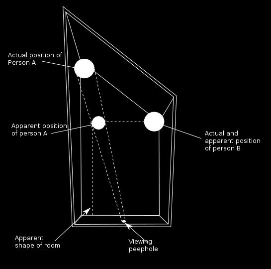
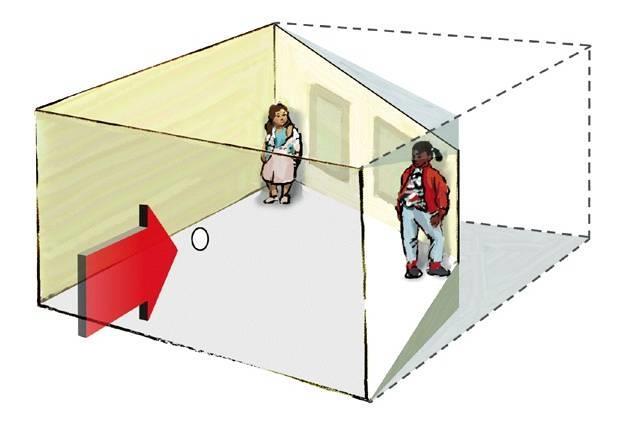
62 The Ames room illusion
63 Other camera models
64 What if real-world object we continue increasing Z and f while maintaining same magnification? depth Z focal length f f and f Z = constant

65 camera is close to object and has small focal length camera is far from object and has large focal length


66 Different cameras perspective camera weak perspective camera
67 Weak perspective vs perspective camera Z o image plane magnification does not change with depth constant magnification depending on f and Z o magnification changes with depth
68 Comparing camera matrices Let s assume that the world and camera coordinate systems are the same. The perspective camera matrix can be written as: What would the matrix of the weak perspective camera look like?

69 Comparing camera matrices Let s assume that the world and camera coordinate systems are the same. The perspective camera matrix can be written as: The weak perspective camera matrix can be written as:


70 Comparing camera matrices Let s assume that the world and camera coordinate systems are the same. The finite projective camera matrix can be written as: The affine camera matrix can be written as: where we now have the more general intrinsic matrix In both cameras, we can incorporate extrinsic parameters same as we did before.
71 When can we assume a weak perspective camera?
 is very far away.")
72 When can we assume a weak perspective camera? 1. When the scene (or parts of it) is very far away. Weak perspective projection applies to the mountains.
73 When can we assume a weak perspective camera? 2. When we use a telecentric lens. Place a pinhole at focal length, so that only rays parallel to primary ray pass through. What is the magnification factor in this case? object distance D focal length f sensor distance D
74 When can we assume a weak perspective camera? 2. When we use a telecentric lens. Place a pinhole at focal length, so that only rays parallel to primary ray pass through. object distance D focal length f sensor distance D m = D f f magnification is constant with depth remember that focal length f refers to different things in pinhole and lens cameras
75 Orthographic camera Special case of weak perspective camera where: constant magnification is equal to 1. there is no shift between camera and image origins. the world and camera coordinate systems are the same. image world What is the camera matrix in this case?
76 Orthographic camera Special case of weak perspective camera where: constant magnification is equal to 1. there is no shift between camera and image origins. the world and camera coordinate systems are the same. image world
77 Orthographic projection using a telecentric lens How do we make the telecentric lens act as an orthographic camera? object distance D focal length f sensor distance D
78 Orthographic projection using a telecentric lens How do we make the telecentric lens act as an orthographic camera? We set the sensor distance as: D = 2f in order to achieve unit magnification. object distance D focal length f sensor distance D
79 Many other types of cameras
80 Geometric camera calibration
81 Geometric camera calibration Given a set of matched points point in 3D space point in the image and camera model projection model parameters Camera matrix Find the (pose) estimate of We ll use a perspective camera model for pose estimation
82 Same setup as homography estimation (slightly different derivation here) Where did we see homography estimation in this class?
83 Mapping between 3D point and image points What are the unknowns?

 How can we make these")
84 Mapping between 3D point and image points Heterogeneous coordinates (non-linear relation between coordinates) How can we make these relations linear?
85 How can we make these relations linear? Make them linear with algebraic manipulation Now we can setup a system of linear equations with multiple point correspondences
86 How do we proceed?
87 In matrix form How do we proceed?


88 In matrix form For N points How do we solve this system?
89 Solve for camera matrix by SVD!
90 Solution x is the column of V corresponding to smallest singular value of Solve for camera matrix by


91 Solve for camera matrix by Equivalently, solution x is the Eigenvector corresponding to smallest Eigenvalue of
92 Now we have: Are we done?
93 Almost there How do you get the intrinsic and extrinsic parameters from the projection matrix?
94 Decomposition of the Camera Matrix
95 Decomposition of the Camera Matrix
96 Decomposition of the Camera Matrix
97 Decomposition of the Camera Matrix Find the camera center C Find intrinsic K and rotation R What is the projection of the camera center?
98 Decomposition of the Camera Matrix Find the camera center C Find intrinsic K and rotation R How do we compute the camera center from this?
99 Decomposition of the Camera Matrix Find the camera center C Find intrinsic K and rotation R SVD of P! c is the Eigenvector corresponding to smallest Eigenvalue
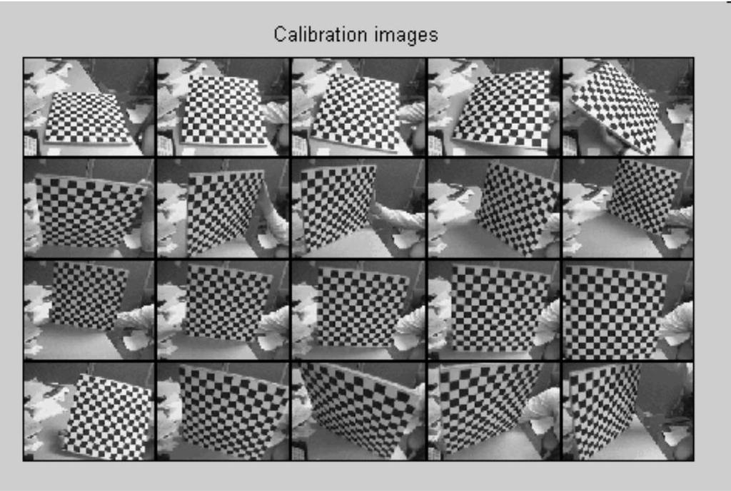
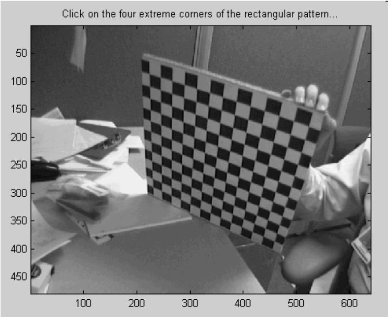
100 Decomposition of the Camera Matrix Find the camera center C Find intrinsic K and rotation R SVD of P! c is the Eigenvector corresponding to smallest Eigenvalue Any useful properties of K and R we can use?
101 Decomposition of the Camera Matrix Find the camera center C Find intrinsic K and rotation R SVD of P! c is the Eigenvector corresponding to smallest Eigenvalue right upper triangle orthogonal How do we find K and R?
102 Decomposition of the Camera Matrix Find the camera center C Find intrinsic K and rotation R SVD of P! c is the Eigenvector corresponding to smallest Eigenvalue QR decomposition
103 Geometric camera calibration Given a set of matched points point in 3D space point in the image Where do we get these matched points from? and camera model projection model parameters Camera matrix Find the (pose) estimate of We ll use a perspective camera model for pose estimation

104 Calibration using a reference object Place a known object in the scene: identify correspondences between image and scene compute mapping from scene to image Issues: must know geometry very accurately must know 3D->2D correspondence
105 Advantages: Very simple to formulate. Analytical solution. Geometric camera calibration Disadvantages: Doesn t model radial distortion. Hard to impose constraints (e.g., known f). Doesn t minimize the correct error function. For these reasons, nonlinear methods are preferred Define error function E between projected 3D points and image positions E is nonlinear function of intrinsics, extrinsics, radial distortion Minimize E using nonlinear optimization techniques
106 P 1 P i (u i,v i ) (u 1,v 1 ) MP i i i i i i i P m P m v P m P m u Minimizing reprojection error Is this equivalent to what we were doing previously?


107 no distortion barrel distortion pincushion distortion Radial distortion What causes this distortion?
108 Radial distortion model
109 Minimizing reprojection error with radial distortion P i (u 1,v 1 ) P 1 MP i (u i,v i ) Add distortions to reprojection error: u i 1 λ m 1 P i m 3 P i 2 + v i 1 λ m 2 P i m 3 P i 2


110 Correcting radial distortion before after

111 Alternative: Multi-plane calibration Advantages: Only requires a plane Don t have to know positions/orientations Great code available online! Matlab version: Also available on OpenCV. Disadvantage: Need to solve non-linear optimization problem.
112 Step-by-step demonstration
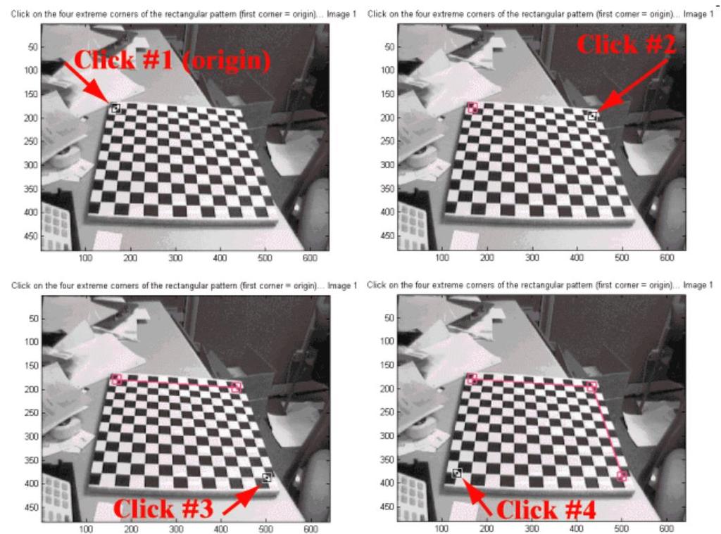
113 Step-by-step demonstration
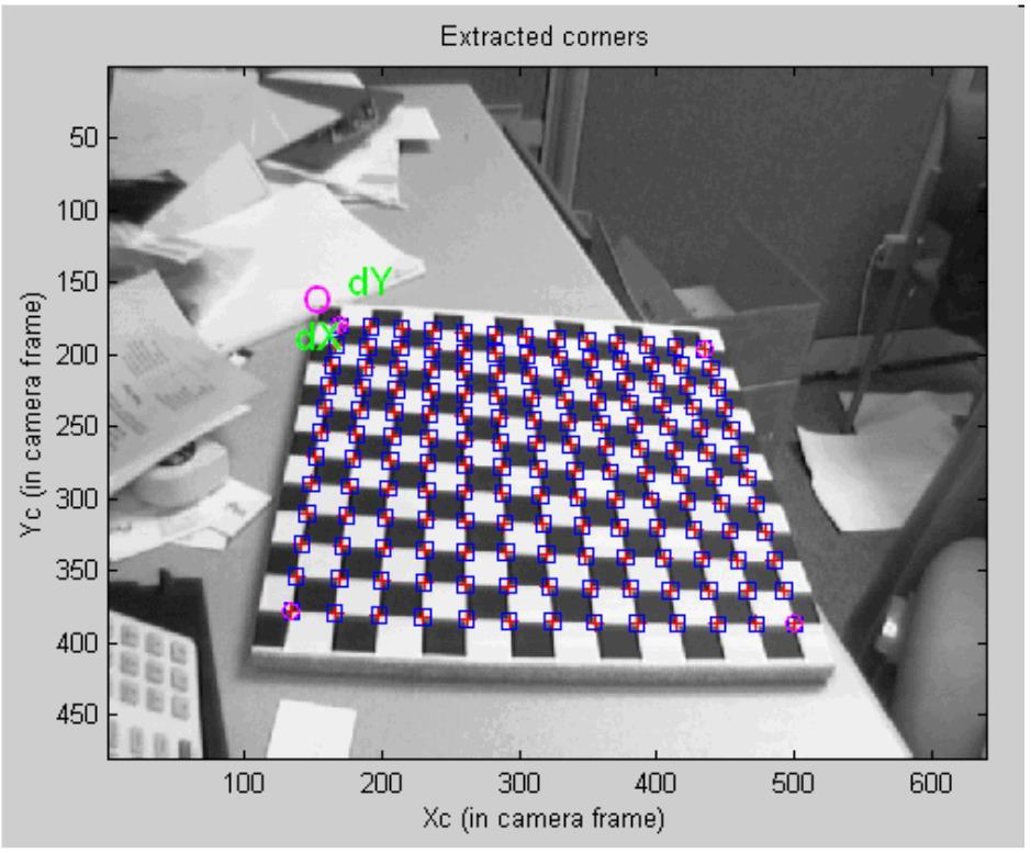
114 Step-by-step demonstration
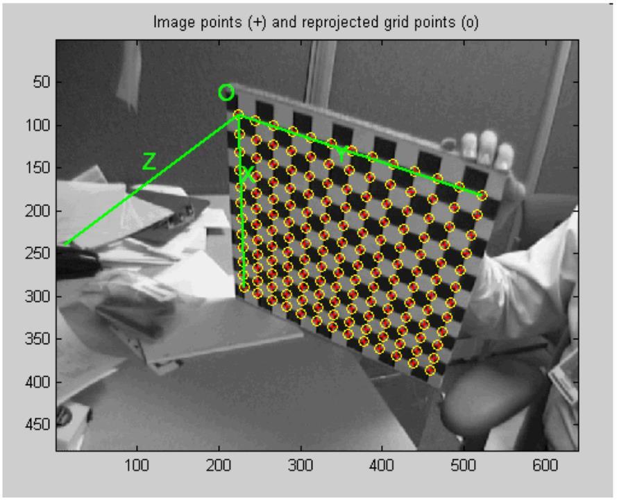
115 Step-by-step demonstration
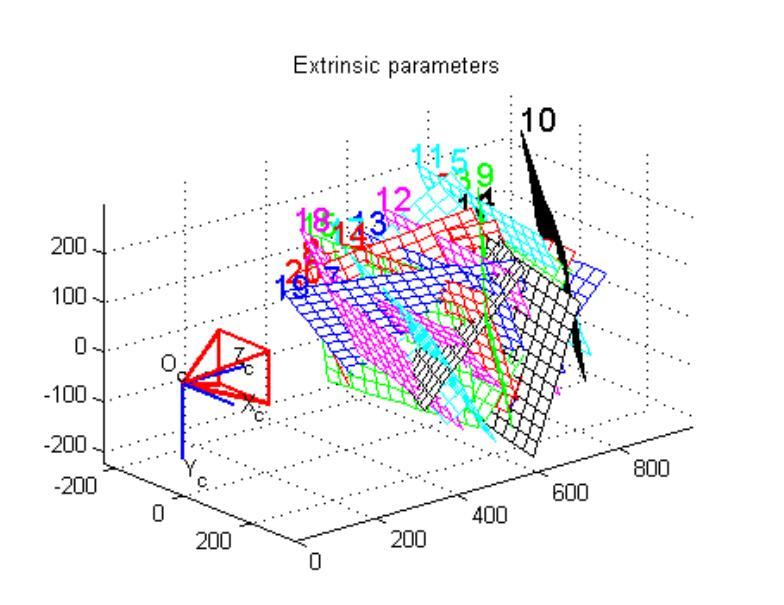
116 Step-by-step demonstration
117 What does it mean to calibrate a camera?
118 What does it mean to calibrate a camera? Many different ways to calibrate a camera: Radiometric calibration. Color calibration. Geometric calibration. Noise calibration. Lens (or aberration) calibration. lecture 5 lecture 6 lecture 13 later lecture lecture 12, (maybe) later lecture
119 References Basic reading: Szeliski textbook, Section 2.1.5, 6.2. Bouguet, Camera calibration toolbox for Matlab, available at The main resource for camera calibration in Matlab, where the screenshots in this lecture were taken from. It also has a detailed of the camera calibration algorithm and an extensive reference section. Additional reading: Hartley and Zisserman, Multiple View Geometry in Computer Vision, Cambridge University Press Chapter 6 of this book has a very thorough treatment of camera models. Gortler, Foundations of 3D Computer Graphics, MIT Press Chapter 10 of this book has a nice discussion of pinhole cameras from a graphics point of view. Zhang, A flexible new technique for camera calibration, PAMI The paper that introduced camera calibration from multiple views of a planar target.
Two-view geometry Computer Vision Spring 2018, Lecture 10
 Two-view geometry http://www.cs.cmu.edu/~16385/ 16-385 Computer Vision Spring 2018, Lecture 10 Course announcements Homework 2 is due on February 23 rd. - Any questions about the homework? - How many of
Pin Hole Cameras & Warp Functions
 Pin Hole Cameras & Warp Functions Instructor - Simon Lucey 16-423 - Designing Computer Vision Apps Today Pinhole Camera. Homogenous Coordinates. Planar Warp Functions. Motivation Taken from: http://img.gawkerassets.com/img/18w7i1umpzoa9jpg/original.jpg
Agenda. Rotations. Camera models. Camera calibration. Homographies
 Agenda Rotations Camera models Camera calibration Homographies D Rotations R Y = Z r r r r r r r r r Y Z Think of as change of basis where ri = r(i,:) are orthonormal basis vectors r rotated coordinate
Vision Review: Image Formation. Course web page:
 Vision Review: Image Formation Course web page: www.cis.udel.edu/~cer/arv September 10, 2002 Announcements Lecture on Thursday will be about Matlab; next Tuesday will be Image Processing The dates some
Pin Hole Cameras & Warp Functions
 Pin Hole Cameras & Warp Functions Instructor - Simon Lucey 16-423 - Designing Computer Vision Apps Today Pinhole Camera. Homogenous Coordinates. Planar Warp Functions. Example of SLAM for AR Taken from:
CS4670: Computer Vision
 CS467: Computer Vision Noah Snavely Lecture 13: Projection, Part 2 Perspective study of a vase by Paolo Uccello Szeliski 2.1.3-2.1.6 Reading Announcements Project 2a due Friday, 8:59pm Project 2b out Friday
calibrated coordinates Linear transformation pixel coordinates
 1 calibrated coordinates Linear transformation pixel coordinates 2 Calibration with a rig Uncalibrated epipolar geometry Ambiguities in image formation Stratified reconstruction Autocalibration with partial
CS6670: Computer Vision
 CS6670: Computer Vision Noah Snavely Lecture 5: Projection Reading: Szeliski 2.1 Projection Reading: Szeliski 2.1 Projection Müller Lyer Illusion http://www.michaelbach.de/ot/sze_muelue/index.html Modeling
Agenda. Rotations. Camera calibration. Homography. Ransac
 Agenda Rotations Camera calibration Homography Ransac Geometric Transformations y x Transformation Matrix # DoF Preserves Icon translation rigid (Euclidean) similarity affine projective h I t h R t h sr
CS6670: Computer Vision
 CS6670: Computer Vision Noah Snavely Lecture 7: Image Alignment and Panoramas What s inside your fridge? http://www.cs.washington.edu/education/courses/cse590ss/01wi/ Projection matrix intrinsics projection
Homogeneous Coordinates. Lecture18: Camera Models. Representation of Line and Point in 2D. Cross Product. Overall scaling is NOT important.
 Homogeneous Coordinates Overall scaling is NOT important. CSED44:Introduction to Computer Vision (207F) Lecture8: Camera Models Bohyung Han CSE, POSTECH bhhan@postech.ac.kr (",, ) ()", ), )) ) 0 It is
Image warping , , Computational Photography Fall 2017, Lecture 10
 Image warping http://graphics.cs.cmu.edu/courses/15-463 15-463, 15-663, 15-862 Computational Photography Fall 2017, Lecture 10 Course announcements Second make-up lecture on Friday, October 6 th, noon-1:30
CS201 Computer Vision Camera Geometry
 CS201 Computer Vision Camera Geometry John Magee 25 November, 2014 Slides Courtesy of: Diane H. Theriault (deht@bu.edu) Question of the Day: How can we represent the relationships between cameras and the
COSC579: Scene Geometry. Jeremy Bolton, PhD Assistant Teaching Professor
 COSC579: Scene Geometry Jeremy Bolton, PhD Assistant Teaching Professor Overview Linear Algebra Review Homogeneous vs non-homogeneous representations Projections and Transformations Scene Geometry The
Rigid Body Motion and Image Formation. Jana Kosecka, CS 482
 Rigid Body Motion and Image Formation Jana Kosecka, CS 482 A free vector is defined by a pair of points : Coordinates of the vector : 1 3D Rotation of Points Euler angles Rotation Matrices in 3D 3 by 3
Structure from motion
 Structure from motion Structure from motion Given a set of corresponding points in two or more images, compute the camera parameters and the 3D point coordinates?? R 1,t 1 R 2,t R 2 3,t 3 Camera 1 Camera
Augmented Reality II - Camera Calibration - Gudrun Klinker May 11, 2004
 Augmented Reality II - Camera Calibration - Gudrun Klinker May, 24 Literature Richard Hartley and Andrew Zisserman, Multiple View Geometry in Computer Vision, Cambridge University Press, 2. (Section 5,
3D Geometry and Camera Calibration
 3D Geometry and Camera Calibration 3D Coordinate Systems Right-handed vs. left-handed x x y z z y 2D Coordinate Systems 3D Geometry Basics y axis up vs. y axis down Origin at center vs. corner Will often
Image correspondences and structure from motion
 Image correspondences and structure from motion http://graphics.cs.cmu.edu/courses/15-463 15-463, 15-663, 15-862 Computational Photography Fall 2017, Lecture 20 Course announcements Homework 5 posted.
Outline. ETN-FPI Training School on Plenoptic Sensing
 Outline Introduction Part I: Basics of Mathematical Optimization Linear Least Squares Nonlinear Optimization Part II: Basics of Computer Vision Camera Model Multi-Camera Model Multi-Camera Calibration
Camera calibration. Robotic vision. Ville Kyrki
 Camera calibration Robotic vision 19.1.2017 Where are we? Images, imaging Image enhancement Feature extraction and matching Image-based tracking Camera models and calibration Pose estimation Motion analysis
Camera Calibration. Schedule. Jesus J Caban. Note: You have until next Monday to let me know. ! Today:! Camera calibration
 Camera Calibration Jesus J Caban Schedule! Today:! Camera calibration! Wednesday:! Lecture: Motion & Optical Flow! Monday:! Lecture: Medical Imaging! Final presentations:! Nov 29 th : W. Griffin! Dec 1
Camera Models and Image Formation. Srikumar Ramalingam School of Computing University of Utah
 Camera Models and Image Formation Srikumar Ramalingam School of Computing University of Utah srikumar@cs.utah.edu Reference Most slides are adapted from the following notes: Some lecture notes on geometric
Camera Models and Image Formation. Srikumar Ramalingam School of Computing University of Utah
 Camera Models and Image Formation Srikumar Ramalingam School of Computing University of Utah srikumar@cs.utah.edu VisualFunHouse.com 3D Street Art Image courtesy: Julian Beaver (VisualFunHouse.com) 3D
More Mosaic Madness. CS194: Image Manipulation & Computational Photography. Steve Seitz and Rick Szeliski. Jeffrey Martin (jeffrey-martin.
 More Mosaic Madness Jeffrey Martin (jeffrey-martin.com) CS194: Image Manipulation & Computational Photography with a lot of slides stolen from Alexei Efros, UC Berkeley, Fall 2018 Steve Seitz and Rick
Computer Vision Projective Geometry and Calibration. Pinhole cameras
 Computer Vision Projective Geometry and Calibration Professor Hager http://www.cs.jhu.edu/~hager Jason Corso http://www.cs.jhu.edu/~jcorso. Pinhole cameras Abstract camera model - box with a small hole
Two-View Geometry (Course 23, Lecture D)
") Two-View Geometry (Course 23, Lecture D) Jana Kosecka Department of Computer Science George Mason University http://www.cs.gmu.edu/~kosecka General Formulation Given two views of the scene recover the
Two-View Geometry (Course 23, Lecture D) Jana Kosecka Department of Computer Science George Mason University http://www.cs.gmu.edu/~kosecka General Formulation Given two views of the scene recover the
55:148 Digital Image Processing Chapter 11 3D Vision, Geometry
 55:148 Digital Image Processing Chapter 11 3D Vision, Geometry Topics: Basics of projective geometry Points and hyperplanes in projective space Homography Estimating homography from point correspondence
Cameras and Stereo CSE 455. Linda Shapiro
 Cameras and Stereo CSE 455 Linda Shapiro 1 Müller-Lyer Illusion http://www.michaelbach.de/ot/sze_muelue/index.html What do you know about perspective projection? Vertical lines? Other lines? 2 Image formation
Lecture 5.3 Camera calibration. Thomas Opsahl
 Lecture 5.3 Camera calibration Thomas Opsahl Introduction The image u u x X W v C z C World frame x C y C z C = 1 For finite projective cameras, the correspondence between points in the world and points
MERGING POINT CLOUDS FROM MULTIPLE KINECTS. Nishant Rai 13th July, 2016 CARIS Lab University of British Columbia
 MERGING POINT CLOUDS FROM MULTIPLE KINECTS Nishant Rai 13th July, 2016 CARIS Lab University of British Columbia Introduction What do we want to do? : Use information (point clouds) from multiple (2+) Kinects
Module 4F12: Computer Vision and Robotics Solutions to Examples Paper 2
 Engineering Tripos Part IIB FOURTH YEAR Module 4F2: Computer Vision and Robotics Solutions to Examples Paper 2. Perspective projection and vanishing points (a) Consider a line in 3D space, defined in camera-centered
Camera Geometry II. COS 429 Princeton University
 Camera Geometry II COS 429 Princeton University Outline Projective geometry Vanishing points Application: camera calibration Application: single-view metrology Epipolar geometry Application: stereo correspondence
Unit 3 Multiple View Geometry
 Unit 3 Multiple View Geometry Relations between images of a scene Recovering the cameras Recovering the scene structure http://www.robots.ox.ac.uk/~vgg/hzbook/hzbook1.html 3D structure from images Recover
Dense 3D Reconstruction. Christiano Gava
 Dense 3D Reconstruction Christiano Gava christiano.gava@dfki.de Outline Previous lecture: structure and motion II Structure and motion loop Triangulation Today: dense 3D reconstruction The matching problem
1 Projective Geometry
 CIS8, Machine Perception Review Problem - SPRING 26 Instructions. All coordinate systems are right handed. Projective Geometry Figure : Facade rectification. I took an image of a rectangular object, and
Homographies and RANSAC
 Homographies and RANSAC Computer vision 6.869 Bill Freeman and Antonio Torralba March 30, 2011 Homographies and RANSAC Homographies RANSAC Building panoramas Phototourism 2 Depth-based ambiguity of position
Structure from motion
 Structure from motion Structure from motion Given a set of corresponding points in two or more images, compute the camera parameters and the 3D point coordinates?? R 1,t 1 R 2,t 2 R 3,t 3 Camera 1 Camera
Image Formation I Chapter 2 (R. Szelisky)
") Image Formation I Chapter 2 (R. Selisky) Guido Gerig CS 632 Spring 22 cknowledgements: Slides used from Prof. Trevor Darrell, (http://www.eecs.berkeley.edu/~trevor/cs28.html) Some slides modified from
Image Formation I Chapter 2 (R. Selisky) Guido Gerig CS 632 Spring 22 cknowledgements: Slides used from Prof. Trevor Darrell, (http://www.eecs.berkeley.edu/~trevor/cs28.html) Some slides modified from
Dense 3D Reconstruction. Christiano Gava
 Dense 3D Reconstruction Christiano Gava christiano.gava@dfki.de Outline Previous lecture: structure and motion II Structure and motion loop Triangulation Wide baseline matching (SIFT) Today: dense 3D reconstruction
Camera Model and Calibration
 Camera Model and Calibration Lecture-10 Camera Calibration Determine extrinsic and intrinsic parameters of camera Extrinsic 3D location and orientation of camera Intrinsic Focal length The size of the
Camera model and multiple view geometry
 Chapter Camera model and multiple view geometry Before discussing how D information can be obtained from images it is important to know how images are formed First the camera model is introduced and then
Computer Vision: Lecture 3
 Computer Vision: Lecture 3 Carl Olsson 2019-01-29 Carl Olsson Computer Vision: Lecture 3 2019-01-29 1 / 28 Todays Lecture Camera Calibration The inner parameters - K. Projective vs. Euclidean Reconstruction.
Cameras and Radiometry. Last lecture in a nutshell. Conversion Euclidean -> Homogenous -> Euclidean. Affine Camera Model. Simplified Camera Models
 Cameras and Radiometry Last lecture in a nutshell CSE 252A Lecture 5 Conversion Euclidean -> Homogenous -> Euclidean In 2-D Euclidean -> Homogenous: (x, y) -> k (x,y,1) Homogenous -> Euclidean: (x, y,
Instance-level recognition I. - Camera geometry and image alignment
 Reconnaissance d objets et vision artificielle 2011 Instance-level recognition I. - Camera geometry and image alignment Josef Sivic http://www.di.ens.fr/~josef INRIA, WILLOW, ENS/INRIA/CNRS UMR 8548 Laboratoire
Geometry of image formation
 eometry of image formation Tomáš Svoboda, svoboda@cmp.felk.cvut.cz Czech Technical University in Prague, Center for Machine Perception http://cmp.felk.cvut.cz Last update: November 3, 2008 Talk Outline
Miniature faking. In close-up photo, the depth of field is limited.
 Miniature faking In close-up photo, the depth of field is limited. http://en.wikipedia.org/wiki/file:jodhpur_tilt_shift.jpg Miniature faking Miniature faking http://en.wikipedia.org/wiki/file:oregon_state_beavers_tilt-shift_miniature_greg_keene.jpg
Recovering structure from a single view Pinhole perspective projection
 EPIPOLAR GEOMETRY The slides are from several sources through James Hays (Brown); Silvio Savarese (U. of Michigan); Svetlana Lazebnik (U. Illinois); Bill Freeman and Antonio Torralba (MIT), including their
Image Formation I Chapter 1 (Forsyth&Ponce) Cameras
 Cameras") Image Formation I Chapter 1 (Forsyth&Ponce) Cameras Guido Gerig CS 632 Spring 215 cknowledgements: Slides used from Prof. Trevor Darrell, (http://www.eecs.berkeley.edu/~trevor/cs28.html) Some slides modified
Image Formation I Chapter 1 (Forsyth&Ponce) Cameras Guido Gerig CS 632 Spring 215 cknowledgements: Slides used from Prof. Trevor Darrell, (http://www.eecs.berkeley.edu/~trevor/cs28.html) Some slides modified
CIS 580, Machine Perception, Spring 2015 Homework 1 Due: :59AM
 CIS 580, Machine Perception, Spring 2015 Homework 1 Due: 2015.02.09. 11:59AM Instructions. Submit your answers in PDF form to Canvas. This is an individual assignment. 1 Camera Model, Focal Length and
Structure from motion
 Structure from motion Structure from motion Given a set of corresponding points in two or more images, compute the camera parameters and the 3D point coordinates?? R 1,t 1 R 2,t 2 R 3,t 3 Camera 1 Camera
Camera models and calibration
 Camera models and calibration Read tutorial chapter 2 and 3. http://www.cs.unc.edu/~marc/tutorial/ Szeliski s book pp.29-73 Schedule (tentative) 2 # date topic Sep.8 Introduction and geometry 2 Sep.25
Image Formation I Chapter 1 (Forsyth&Ponce) Cameras
 Cameras") Image Formation I Chapter 1 (Forsyth&Ponce) Cameras Guido Gerig CS 632 Spring 213 cknowledgements: Slides used from Prof. Trevor Darrell, (http://www.eecs.berkeley.edu/~trevor/cs28.html) Some slides modified
Image Formation I Chapter 1 (Forsyth&Ponce) Cameras Guido Gerig CS 632 Spring 213 cknowledgements: Slides used from Prof. Trevor Darrell, (http://www.eecs.berkeley.edu/~trevor/cs28.html) Some slides modified
Visual Recognition: Image Formation
 Visual Recognition: Image Formation Raquel Urtasun TTI Chicago Jan 5, 2012 Raquel Urtasun (TTI-C) Visual Recognition Jan 5, 2012 1 / 61 Today s lecture... Fundamentals of image formation You should know
ECE 470: Homework 5. Due Tuesday, October 27 in Seth Hutchinson. Luke A. Wendt
 ECE 47: Homework 5 Due Tuesday, October 7 in class @:3pm Seth Hutchinson Luke A Wendt ECE 47 : Homework 5 Consider a camera with focal length λ = Suppose the optical axis of the camera is aligned with
Today. Stereo (two view) reconstruction. Multiview geometry. Today. Multiview geometry. Computational Photography
 reconstruction. Multiview geometry. Today. Multiview geometry. Computational Photography") Computational Photography Matthias Zwicker University of Bern Fall 2009 Today From 2D to 3D using multiple views Introduction Geometry of two views Stereo matching Other applications Multiview geometry
Computational Photography Matthias Zwicker University of Bern Fall 2009 Today From 2D to 3D using multiple views Introduction Geometry of two views Stereo matching Other applications Multiview geometry
Image Formation. Antonino Furnari. Image Processing Lab Dipartimento di Matematica e Informatica Università degli Studi di Catania
 Image Formation Antonino Furnari Image Processing Lab Dipartimento di Matematica e Informatica Università degli Studi di Catania furnari@dmi.unict.it 18/03/2014 Outline Introduction; Geometric Primitives
Lecture 3: Camera Calibration, DLT, SVD
 Computer Vision Lecture 3 23--28 Lecture 3: Camera Calibration, DL, SVD he Inner Parameters In this section we will introduce the inner parameters of the cameras Recall from the camera equations λx = P
Reminder: Lecture 20: The Eight-Point Algorithm. Essential/Fundamental Matrix. E/F Matrix Summary. Computing F. Computing F from Point Matches
 Reminder: Lecture 20: The Eight-Point Algorithm F = -0.00310695-0.0025646 2.96584-0.028094-0.00771621 56.3813 13.1905-29.2007-9999.79 Readings T&V 7.3 and 7.4 Essential/Fundamental Matrix E/F Matrix Summary
Robot Vision: Camera calibration
 Robot Vision: Camera calibration Ass.Prof. Friedrich Fraundorfer SS 201 1 Outline Camera calibration Cameras with lenses Properties of real lenses (distortions, focal length, field-of-view) Calibration
Introduction to Computer Vision
 Introduction to Computer Vision Michael J. Black Nov 2009 Perspective projection and affine motion Goals Today Perspective projection 3D motion Wed Projects Friday Regularization and robust statistics
3-D D Euclidean Space - Vectors
 3-D D Euclidean Space - Vectors Rigid Body Motion and Image Formation A free vector is defined by a pair of points : Jana Kosecka http://cs.gmu.edu/~kosecka/cs682.html Coordinates of the vector : 3D Rotation
CSE 252B: Computer Vision II
 CSE 252B: Computer Vision II Lecturer: Serge Belongie Scribe: Sameer Agarwal LECTURE 1 Image Formation 1.1. The geometry of image formation We begin by considering the process of image formation when a
Geometry of a single camera. Odilon Redon, Cyclops, 1914
 Geometr o a single camera Odilon Redon, Cclops, 94 Our goal: Recover o 3D structure Recover o structure rom one image is inherentl ambiguous??? Single-view ambiguit Single-view ambiguit Rashad Alakbarov
Rectification and Distortion Correction
 Rectification and Distortion Correction Hagen Spies March 12, 2003 Computer Vision Laboratory Department of Electrical Engineering Linköping University, Sweden Contents Distortion Correction Rectification
Computer Vision Lecture 17
 Computer Vision Lecture 17 Epipolar Geometry & Stereo Basics 13.01.2015 Bastian Leibe RWTH Aachen http://www.vision.rwth-aachen.de leibe@vision.rwth-aachen.de Announcements Seminar in the summer semester
COMP 558 lecture 19 Nov. 17, 2010
 COMP 558 lecture 9 Nov. 7, 2 Camera calibration To estimate the geometry of 3D scenes, it helps to know the camera parameters, both external and internal. The problem of finding all these parameters is
Lecture 9: Epipolar Geometry
 Lecture 9: Epipolar Geometry Professor Fei Fei Li Stanford Vision Lab 1 What we will learn today? Why is stereo useful? Epipolar constraints Essential and fundamental matrix Estimating F (Problem Set 2
3D Vision Real Objects, Real Cameras. Chapter 11 (parts of), 12 (parts of) Computerized Image Analysis MN2 Anders Brun,
, 12 (parts of) Computerized Image Analysis MN2 Anders Brun,") 3D Vision Real Objects, Real Cameras Chapter 11 (parts of), 12 (parts of) Computerized Image Analysis MN2 Anders Brun, anders@cb.uu.se 3D Vision! Philisophy! Image formation " The pinhole camera " Projective
3D Vision Real Objects, Real Cameras Chapter 11 (parts of), 12 (parts of) Computerized Image Analysis MN2 Anders Brun, anders@cb.uu.se 3D Vision! Philisophy! Image formation " The pinhole camera " Projective
Computer Vision Lecture 17
 Announcements Computer Vision Lecture 17 Epipolar Geometry & Stereo Basics Seminar in the summer semester Current Topics in Computer Vision and Machine Learning Block seminar, presentations in 1 st week
Camera Calibration. COS 429 Princeton University
 Camera Calibration COS 429 Princeton University Point Correspondences What can you figure out from point correspondences? Noah Snavely Point Correspondences X 1 X 4 X 3 X 2 X 5 X 6 X 7 p 1,1 p 1,2 p 1,3
CS231A Course Notes 4: Stereo Systems and Structure from Motion
 CS231A Course Notes 4: Stereo Systems and Structure from Motion Kenji Hata and Silvio Savarese 1 Introduction In the previous notes, we covered how adding additional viewpoints of a scene can greatly enhance
Assignment 2 : Projection and Homography
 TECHNISCHE UNIVERSITÄT DRESDEN EINFÜHRUNGSPRAKTIKUM COMPUTER VISION Assignment 2 : Projection and Homography Hassan Abu Alhaija November 7,204 INTRODUCTION In this exercise session we will get a hands-on
The real voyage of discovery consists not in seeking new landscapes, but in having new eyes.
 The real voyage of discovery consists not in seeking new landscapes, but in having new eyes. - Marcel Proust University of Texas at Arlington Camera Calibration (or Resectioning) CSE 4392-5369 Vision-based
C18 Computer Vision. Lecture 1 Introduction: imaging geometry, camera calibration. Victor Adrian Prisacariu.
 C8 Computer Vision Lecture Introduction: imaging geometry, camera calibration Victor Adrian Prisacariu http://www.robots.ox.ac.uk/~victor InfiniTAM Demo Course Content VP: Intro, basic image features,
CS 664 Slides #9 Multi-Camera Geometry. Prof. Dan Huttenlocher Fall 2003
 CS 664 Slides #9 Multi-Camera Geometry Prof. Dan Huttenlocher Fall 2003 Pinhole Camera Geometric model of camera projection Image plane I, which rays intersect Camera center C, through which all rays pass
Hartley - Zisserman reading club. Part I: Hartley and Zisserman Appendix 6: Part II: Zhengyou Zhang: Presented by Daniel Fontijne
 Hartley - Zisserman reading club Part I: Hartley and Zisserman Appendix 6: Iterative estimation methods Part II: Zhengyou Zhang: A Flexible New Technique for Camera Calibration Presented by Daniel Fontijne
Index. 3D reconstruction, point algorithm, point algorithm, point algorithm, point algorithm, 263
 Index 3D reconstruction, 125 5+1-point algorithm, 284 5-point algorithm, 270 7-point algorithm, 265 8-point algorithm, 263 affine point, 45 affine transformation, 57 affine transformation group, 57 affine
Week 2: Two-View Geometry. Padua Summer 08 Frank Dellaert
 Week 2: Two-View Geometry Padua Summer 08 Frank Dellaert Mosaicking Outline 2D Transformation Hierarchy RANSAC Triangulation of 3D Points Cameras Triangulation via SVD Automatic Correspondence Essential
Structure from Motion. Introduction to Computer Vision CSE 152 Lecture 10
 Structure from Motion CSE 152 Lecture 10 Announcements Homework 3 is due May 9, 11:59 PM Reading: Chapter 8: Structure from Motion Optional: Multiple View Geometry in Computer Vision, 2nd edition, Hartley
DD2423 Image Analysis and Computer Vision IMAGE FORMATION. Computational Vision and Active Perception School of Computer Science and Communication
 DD2423 Image Analysis and Computer Vision IMAGE FORMATION Mårten Björkman Computational Vision and Active Perception School of Computer Science and Communication November 8, 2013 1 Image formation Goal:
Colorado School of Mines. Computer Vision. Professor William Hoff Dept of Electrical Engineering &Computer Science.
 Professor Willia Hoff Dept of Electrical Engineering &Coputer Science http://inside.ines.edu/~whoff/ 1 Caera Calibration 2 Caera Calibration Needed for ost achine vision and photograetry tasks (object
Index. 3D reconstruction, point algorithm, point algorithm, point algorithm, point algorithm, 253
 Index 3D reconstruction, 123 5+1-point algorithm, 274 5-point algorithm, 260 7-point algorithm, 255 8-point algorithm, 253 affine point, 43 affine transformation, 55 affine transformation group, 55 affine
Epipolar Geometry and Stereo Vision
 CS 1699: Intro to Computer Vision Epipolar Geometry and Stereo Vision Prof. Adriana Kovashka University of Pittsburgh October 8, 2015 Today Review Projective transforms Image stitching (homography) Epipolar
Stereo II CSE 576. Ali Farhadi. Several slides from Larry Zitnick and Steve Seitz
 Stereo II CSE 576 Ali Farhadi Several slides from Larry Zitnick and Steve Seitz Camera parameters A camera is described by several parameters Translation T of the optical center from the origin of world
Stereo CSE 576. Ali Farhadi. Several slides from Larry Zitnick and Steve Seitz
 Stereo CSE 576 Ali Farhadi Several slides from Larry Zitnick and Steve Seitz Why do we perceive depth? What do humans use as depth cues? Motion Convergence When watching an object close to us, our eyes
Projective Geometry and Camera Models
 Projective Geometry and Camera Models Computer Vision CS 43 Brown James Hays Slides from Derek Hoiem, Alexei Efros, Steve Seitz, and David Forsyth Administrative Stuff My Office hours, CIT 375 Monday and
BIL Computer Vision Apr 16, 2014
 BIL 719 - Computer Vision Apr 16, 2014 Binocular Stereo (cont d.), Structure from Motion Aykut Erdem Dept. of Computer Engineering Hacettepe University Slide credit: S. Lazebnik Basic stereo matching algorithm
Epipolar Geometry and Stereo Vision
 Epipolar Geometry and Stereo Vision Computer Vision Jia-Bin Huang, Virginia Tech Many slides from S. Seitz and D. Hoiem Last class: Image Stitching Two images with rotation/zoom but no translation. X x
Humanoid Robotics. Projective Geometry, Homogeneous Coordinates. (brief introduction) Maren Bennewitz
 Maren Bennewitz") Humanoid Robotics Projective Geometry, Homogeneous Coordinates (brief introduction) Maren Bennewitz Motivation Cameras generate a projected image of the 3D world In Euclidian geometry, the math for describing
Humanoid Robotics Projective Geometry, Homogeneous Coordinates (brief introduction) Maren Bennewitz Motivation Cameras generate a projected image of the 3D world In Euclidian geometry, the math for describing
Interlude: Solving systems of Equations
 Interlude: Solving systems of Equations Solving Ax = b What happens to x under Ax? The singular value decomposition Rotation matrices Singular matrices Condition number Null space Solving Ax = 0 under
Stereo and Epipolar geometry
 Previously Image Primitives (feature points, lines, contours) Today: Stereo and Epipolar geometry How to match primitives between two (multiple) views) Goals: 3D reconstruction, recognition Jana Kosecka
Single-view 3D Reconstruction
 Single-view 3D Reconstruction 10/12/17 Computational Photography Derek Hoiem, University of Illinois Some slides from Alyosha Efros, Steve Seitz Notes about Project 4 (Image-based Lighting) You can work
Computer Vision Projective Geometry and Calibration. Pinhole cameras
 Computer Vision Projective Geometry and Calibration Professor Hager http://www.cs.jhu.edu/~hager Jason Corso http://www.cs.jhu.edu/~jcorso. Pinhole cameras Abstract camera model - box with a small hole
Epipolar Geometry and Stereo Vision
 Epipolar Geometry and Stereo Vision Computer Vision Shiv Ram Dubey, IIIT Sri City Many slides from S. Seitz and D. Hoiem Last class: Image Stitching Two images with rotation/zoom but no translation. X
Focal stacks and lightfields
 Focal stacks and lightfields http://graphics.cs.cmu.edu/courses/15-463 15-463, 15-663, 15-862 Computational Photography Fall 2018, Lecture 11 Course announcements Homework 3 is out. - Due October 12 th.
Camera Model and Calibration. Lecture-12
 Camera Model and Calibration Lecture-12 Camera Calibration Determine extrinsic and intrinsic parameters of camera Extrinsic 3D location and orientation of camera Intrinsic Focal length The size of the
Computer Vision CSCI-GA Assignment 1.
 Computer Vision CSCI-GA.2272-001 Assignment 1. September 22, 2017 Introduction This assignment explores various methods for aligning images and feature extraction. There are four parts to the assignment:
An idea which can be used once is a trick. If it can be used more than once it becomes a method
 An idea which can be used once is a trick. If it can be used more than once it becomes a method - George Polya and Gabor Szego University of Texas at Arlington Rigid Body Transformations & Generalized
Pinhole Camera Model 10/05/17. Computational Photography Derek Hoiem, University of Illinois
 Pinhole Camera Model /5/7 Computational Photography Derek Hoiem, University of Illinois Next classes: Single-view Geometry How tall is this woman? How high is the camera? What is the camera rotation? What