Cinema Pro JR Operations Manual
|
|
|
- Jayson Harrell
- 6 years ago
- Views:
Transcription


1 Cinema Pro JR Operations Manual - 1 -
2 BEFORE YOU START, READ THESE WARNINGS 1) NEVER PLUG POWER DEVICES OTHER THAN THOSE SUPPLIED BY VARIZOOM INTO THE SYSTEM. ONLY USE VARIZOOM POWER SOURCES AND CABLES. USING DIFFERENT POWER COMPONENTS CAN LEAD TO SEVERE DAMAGE TO THE HEAD AND EVEN THE CAMERA. THIS TYPE OF DAMAGE IS NOT COVERED UNDER WARRANTY. 2) DO NOT MODIFY THE SUPPLIED CABLES OR ATTEMPT TO DISASSEMBLE THE HEAD. 3) LENS CONTROL CABLES MUST ONLY BE PLUGGED INTO THE SPECIFIED INPUT JACK ON THE LENS ITSELF NEVER PLUG A 12-PIN CONNECTOR ON A VARIZOOM LENS CONTROL CABLE INTO THE 12PIN JACK ON THE CAMERA BODY. WHEN IN DOUBT, CONSULT VARIZOOM OR YOUR LENS MANUAL. 4) THE ADVANCED CONTROLLER DOES NOT REQUIRE SEPARATE POWER, IT RECEIVES POWER THROUGH THE GREEN-CODED CONTROL CABLE THAT CONNECTS TO THE HEAD. THE AUX POWER JACK ON THE ADVANCED CONTROLLER IS ONLY UTILIZED IN WIRELESS CONFIGURATIONS AND SHOULD ONLY BE CONNECTED TO A VARIZOOM POWER SUPPLY. 5) DO NOT OPERATE THE HEAD WITH AN UNBALANCED LOAD (i.e., with the camera s weight extremely off-center either horizontally or vertically). 6) DO NOT GET THE SYSTEM WET IT IS NOT WATERPROOF. 7) ALWAYS MAKE SURE YOUR LENS AND POWER CABLES HAVE ENOUGH SLACK RUNNING THROUGH THE TILT AXIS TO PREVENT TWISTING AND TEARING OF THE CABLES. 8) MAKE SURE YOUR LENS CLEARS THE BASE OF THE HEAD WHEN TILTING. IF THE LENS DOES NOT CLEAR THE BASE, SET SOFT LIMITS (SECTION 7) TO PREVENT THE LENS FROM STRIKING THE BASE OF THE HEAD WHEN TILTING. 9) WHEN USING THE CP JR s ONBOARD LENS CONTROLS TO CONTROL YOUR CAMERA, ALWAYS POWER THE CAMERA UP LAST. OTHERWISE, THE RECORD START/STOP FEATURE MAY FALL OUT OF SYNC. TO AVOID THIS ISSUE, JUST MAKE SURE TO CONNECT XLR POWER TO THE HEAD BEFORE YOU TURN YOUR CAMERA ON
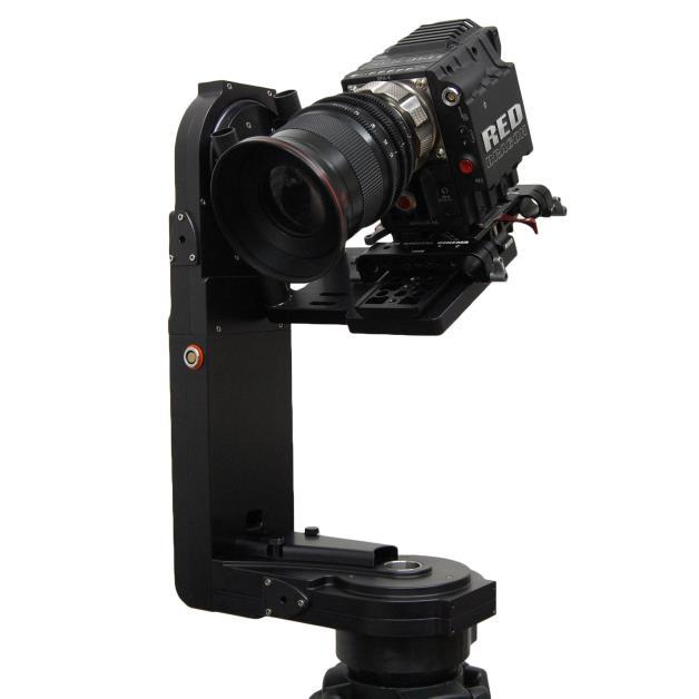
3 General Description The CinemaPro JR is a lightweight, two-axis motion control head for film and video cameras. It has a wide variety of operating modes: manual operation from joystick, motion control style record and playback, go to mark preset framing. Software upgrade options are also available for additional features such as intervalometer, camera sync, PC data share, and additional recorded takes and mark points. The Cinema Pro JR Advanced Controller gives the user all input and programming capabilities and has a joystick for pan & tilt control. The Advanced Controller also works in concert with two optional control input devices: Pan Bars for broadcast-style operation or Hand Wheels for cinemastyle operation. The Jibstick remote is a simpler, less expensive controller designed for one-man jib operation. The jibstick only offers joystick pan & tilt with smoothing and speed control. The Cinema Pro JR s lens interface controls zoom and focus. It handles several control signals: RS-232 for Fujinon digital lenses or Varizoom (TOC) motor drives, RS-422 for Canon digital lenses or Preston motor drives, position or speed based analog, pulse width type RC servos, and LANC. The following is an in-depth description of Cinema Pro JR operation and a more complete description of each of its features. Cinema Pro JR Advanced Controller Front Panel buttons: The top row of buttons default to act like a normal record - playback system; record, rewind, stop and play. The top left button, Q, is used as a Shift key. The bottom row includes: The Menu button = * The Accept button = <- The Cancel button = x The main page may always be enabled by pressing the Cancel button one to three times, depending on which sub-menu you start out from

 will also be used to change the value of selected parameters.")
4 The upper right portion of the LCD screen shows motor status and current positions for pan, tilt, zoom and focus. A check in the box to the left of the axis name indicates that that motor is enabled to run. If soft limits are enabled for the axis, the box is filled and appears white with a blue check mark. The numbers to the right of the axis names are the motor positions; pan and tilt are shown in degrees, and zoom and focus are shown as an unscaled number from 0 to Navigating the menu screens Use the knob above the joystick to navigate through the menu screen. This knob (called the setup knob) will also be used to change the value of selected parameters. Use the enter button to select an item. The Menu button is used to enter setup menu. When pressed while already in the setup menu, the Menu button will enter a second setup menu


5 The cancel button is used to cancel the last item changed, or to back out of a sub menu. Pressing cancel twice will always return to the main screen. The Q button is basically a shift key, and is used to change the function of other buttons. The Record rev stop and play are used for the motion control features. This will be addressed later on. The main menu screen will show pan, tilt, zoom, and focus positions. It will also display which take is enabled, which go to mark is enabled, as well as a few basic functionality adjustments. When changing the value of a parameter, the setup knob will increase or decrease the value in increments of 1. Hold the Q button while moving the setup knob, and the values will move in increments of 10. Hold the menu button while moving the setup knob, and values will move in increments of 100. Hold both the Q and menu buttons while moving the setup knob, and the values will change in increments of 1,000. Display Contrast can be adjusted from the second setup menu. While in the main screen, press the menu button twice. Select the contrast option. Contrast can be adjusted from Basic Setup -Secure the head to crane, tripod, or solid mounting beam -Plug the FACTORY POWER SUPPLY into AC mains -Connect XLR cable between head and FACTORY POWER SUPPLY -Plug green control cable into the head and the jack marked CTRL on the Advanced Controller (or Jibstick, if applicable) -If applicable, connect camera power (red) and lens control cables (orange) and route the cables through the tilt axis port hole to connect to your camera -Make sure to turn camera power on as the LAST step
.")
 between the orange 16-PIN lens control connector located on the head, and the grey control connector located on the TOC 3A.")

6 Feeding External Cables through the Head In some cases, you will need to feed video or other cables through the head. To do so, simply remove the cable covers (pictured at right, covers may differ slightly in appearance). 4 screws secure the long vertical cable cover, while only 2 screws secure the short horizontal cover. Run the cables through the pan base and tilt arm with enough slack, and reattach the cable covers. If using the TOC system Connect the TOC 3A (3 axis lens drive box) between the orange 16-PIN lens control connector located on the head, and the grey control connector located on the TOC 3A. Connect the Lens drive motors to the appropriate connection according to their function (zoom, focus, iris) Balance the Camera Although the head will hold position very well, it operates best when the camera is balanced on the mounting platform. With heavier cameras, it is essential, as an out-of-balance load will cause the servos to constantly fight to hold position. Make sure that the motor power is turned off before balancing. This will allow you to move the tilt axis by hand. To balance the camera horizontally, you need to place the camera s front-to-back center of mass at the center of the mounting platform slot. You can do this by trial and error, sliding the camera front-to-back on the mounting platform until it stays level. The simplest accurate way to find the camera s center of mass is to lay a pencil/pen on a table and try to balance the camera on it front-to-back. The spot on the camera where it comes closest to balancing on the pencil is the center of mass. Place the camera s center of mass at the center of the mounting slot and secure the Center of Mass camera with mounting screws (2 if possible). When horizontally balanced, the platform should stay level. To get the vertical balance right, raise or lower the platform to get the camera s vertical center of mass located on the center of tilt rotation. To adjust, loosen the platform locking lever about ½ turn. Turn the black knob on the underside of - 6 -


7 the platform to precisely raise or lower it you can use a hex key. Try to get the center of mass right on the center of tilt rotation. Rotate the platform to various angles and adjust until it holds position at any angle. If it falls down, you need to adjust the platform upward. If it drifts upward, you need to lower the platform. When balance is achieved, tighten the platform locking lever. After all connections have been made and the camera is balanced, the head is ready to be powered up. Connect the power supply to AC power. Switch on the Advanced Controller s power in sequence: start with the switch on the left. Wait for sync to be established - a spinning diamond will appear in the lower left corner of the remote. After the diamond stops spinning, sync is established between the Head and the controller. Now switch on motor power (the power switch on the right) Set inputs- You will now need to set the Head to respond to the correct controller inputs. Press the menu button to bring up the setup menu. Select the inputs option. This will bring up a controller inputs grid. Here is where you can assign how Pan, Tilt, Zoom, and Focus will be controlled. Move the cursor box to where you d like to control each axis. Note: Make sure you have the correct controller selected. I.E. if you are using the joystick, check mark all boxes next to Joystick ; if using wheels, make sure wheels is selected, etc. This will greatly affect the performance of the Head. Overslung/Underslung- Make sure this selected for the proper configuration. If this needs to be changed, simply move the cursor box over the selection, and press enter. This will change the Pan response

8 Lens- This only needs to be changed if you are using camera lens controls other than the VariZoom TOC system. In other words, if you re connecting directly to a Canon or Fujinon lens servo, or even a Preston system, you ll need to go into this menu to set things up properly. Press the menu button to enter the main setup menu. Select the Lens option. When the Current Lens box is selected, pressing enter will change the selection. Preston If you are using a Preston MDR2, press the enter button until the box reads Preston. Canon or Fujinon Analog Servos If you are using a Canon or Fujinon lens with an analog zoom motor, press the enter button until default appears. Connect the Lens Control Cable To set up the lens control, you need to first connect the lens cable to the servo jack(s) on the lens itself (NEVER connect to the jack on the camera body where the lens plugs in, or damage may occur). You will plug into the same jack(s) where you would plug in any external lens control, so consult your owner s manual if necessary. Adjust the Voltages You must then adjust the voltages in the lens menu so the lens servo responds properly you may notice the lens zooming on its own when you first connect the cable, but this is normal. Start by adjusting the middle number until the lens servo stops zooming. If the lens is all the way at one end of the range, you may have manually zoom the lens in or out to reset the position in order to see if the servo is still moving. (Some people also flip the lens servo switch to manual and just listen to hear the servomotor stop running) Once you ve set the middle number to the proper rest voltage, you need to make sure the voltages on the left and right are equally far from the middle rest voltage. In other words, if your rest voltage is 4.00, the left voltage could be 1.50 and the right If the difference is unequal, you ll notice the lens zooms faster in one direction than the other. The greater the difference, the faster the lens will zoom in that direction. The left number should always be lower than the middle number and the right number should always be higher than the middle number
9 Canon or Fujinon Digital Servos If you are using a Canon or Fujinon lens with digital servos, press enter until the lens manufacturer s name appears. Digital servos should automatically work with no setup. Head Setup You only need to enter this menu to switch the head between wired and wireless mode. Press the menu button twice to enter the secondary setup menu. Select the Head setup option. - Using the Head in Wired Mode: Select head type setting should be on Wired - Using the Head in Wireless Mode: Select head type setting should be on Wireless Warning: In the Head setup menu, there is also a set of head speed options: S- Standard, HS - High Speed and HSX Ultra Speed DO NOT CHANGE THIS SETTING FROM S Standard THE CP JR SHOULD ALWAYS BE SET TO S - Standard. 3. Basic operation and adjustments WARNING: If your lens has an optical image stabilizer (OIS), we recommend that you disable the OIS. The motion of the CP JR may cause the OIS to exhibit some strange behavior. In some cases, the OIS may create the illusion that the head is drifting at 90 degrees to the axis of motion (e.g., at the end of a pan move, the image may tilt slightly up or down). Turn off the OIS to prevent optical problems. The Head can control Pan, Tilt, Zoom, Focus, and record start/stop (when available from the camera and with optional cables attached) from the advanced controller, and has programmable parameters for each axis. Iris can also be controlled from an optional FIZ controller. Pan, tilt, and zoom can be controlled with the joystick by moving the joystick forward, backward, left, right, or twist for zoom. Focus is controlled with the knob to the left Pan and Tilt can also be controlled by using the optional encoded handwheels or with the optional panbar controller pan and tilt to be controlled as if using a fluid head. This can also be fitted with optional Pro style zoom and focus controls.. Record start/stop is done by holding the Q button and pressing the enter: button. A C (for camera) will appear next to the Go To option when camera record has started. Note that the record start/stop feature may be thrown out of sync if you connect XLR power to the head while the camera is powered up make sure the camera is off when you plug power into the head
.")
10 Speed adjustment Basic speed adjustment for pan and tilt can be made in the main menu screen. Move the cursor box to spd using the setup knob, and press enter. The setup knob will then change the speed for both pan and tilt (the number shown in the box is a percentage of the advanced speed setting). Pressing the enter button again will allow you to change the advanced speed setting. In this menu the setup knob will adjust tilt speed, and the focus knob will adjust pan speed. The number shown in the box is a percentage of full speed capability. Press enter again to keep your selection, and return to the main screen. 4. Motion Response From the main screen press the menu button, Select the response menu. Here you can adjust parameters for Pan, Tilt, zoom, and focus. Select the axis that you d like to adjust. Smoothing will adjust how quick the axis will respond. Smoothing can be adjusted from being instant response, and 100 being the maximum delay in response. Smoothing will also affect the how quick the axis will slow down while making the move. Speed will adjust the advanced speed setting. The numbers in the box are the same numbers that appear in the advanced speed setting accessible from the main screen. Deadband only affects the joystick. It will adjust the amount the joystick must be moved before the axis responds. Deadband can be adjusted from being minimum amount of movement before response, and 100 being maximum amount of movement before response. Direction- In will change the direction in which the signal is sent to the head. It is what you will need to change to reverse axis responds. I.E. if tilt is set + turning the encoded wheel clockwise will tilt the camera up, and pressing the joystick forward will tilt the camera down. If it is changed to turning the encoded wheel clockwise will tilt the camera down, and pressing the joystick forward will tilt the camera up

11 Direction- Out will change the direction in which the head sends the signal back to the controller. This will change the axis positions on the main screen display as they relate to zero. I.E. a pan maneuver from left to right will have decrease the angle if the output direction is marked as+. Switching the output direction to will result in the angle number increasing when a pan maneuver is made from left to right. 5. Motor Enable/Disable To enable or disable control of pan, tilt, zoom, or focus, or to place pan or tilt in neutral, while in the main screen select the ENL option. The cursor box then appears in the top right corner, and lets you select one of the four axes. Move the cursor over which axis you wish to control. Pressing enter will disable, or enable that axis from the controller. When disabled, power will remain to this axis, so it will hold its position. It will just be disabled from control. While holding Menu, press the enter button. This will place the selected axis (this only works for pan or tilt) in neutral. That axis not only will be disabled from the controller, and will no longer be powered allowing you to move the axis by hand. From this menu, you can also set each axis for live playback, or manual control (this only applies when playing back a move which will be addressed in a later chapter) Note: A check mark next to the axis indicated that the axis is enabled. An x next to the axis indicates the axis is disabled. An o next to the axis indicates an axis that is in neutral. A blue check mark with a white background indicates an axis with a soft limit set If the name of the axis appears blue with a white background, this indicates an axis that is set for live control during playback of a move (this will be addressed in a later chapter)

12 6. Setting Zero You can custom set the axis position indicator to read zero wherever is necessary. Move each axis to your desired zero point**. From the main screen select the set option. Then a sup menu will appear to the right. Select the zero option. All axes will then reference their current position as zero. **If using the TOC system, Preston MDR2, or any Canon of Fujinon lens with digital servo control. Setting zero will only affect pan and tilt. Zoom, and focus will be referenced to the actual motor position. You can always return all axes to zero at any time. From the main screen, select Go To From the sub menu, select Zero All axis will then return to the zero position 7. Soft Limits Soft limits will allow you to limit the range of the pan, tilt, zoom, or focus axes. This is very useful if you have any hard wired cables that will restrict pan or tilt movement, or any lenses that limit clearance. You can set two limits per axis. From the main screen select the set option. A sub menu then will appear to the right. Select the soft limits option. Select the axis that you d like to set soft limits. When setting a limit, leave the soft limit as disabled Move the selected axis to the desired limit. Then select set limit Now move the axis in the other direction to where you need the other limit set. Select set limit

13 Now move the cursor box to Disabled, and press enter The box now shows enabled, and your soft limits are set that that particular axis. Note: If the system is set up to be in one-way mode, you can quickly enable or disable pan and tilt soft limits from the main screen. While in the main screen Hold Q and press record. This will enable or disable pan and tilt soft limits. Reset Zero will set the current position of the selected axis to read as zero. Set Default will automatically set the selected axis to +90 and 90 from its current position. This is just for a quick limit set that doesn t require the operator to have the head in any direction. Reference is the point from where the soft limits are set. For the CPJR, it can only be set to Zero. 8. Mark points Mark points will be limited to 2 with the basic remote software installed. (A software upgrade allowing for 2,000 mark points is available as an optional upgrade). Marks will set preset positions for all available axes. Setting Marks To set a mark point, select Mark on the main screen. The number in the box will indicate where your mark will be stored. As you scroll through the numbers, the lower right will display the current positions recorded for each mark. Once you choose where you want to store the mark, press enter Move the axes to the position that you wish them to set for this mark position. Select the set option. From the sub menu select Mark This will then record all current axes positions to the mark displayed in the upper left
 Select the Go To option From the sub menu, select Mark All axes will go to the position that is recorded for this mark.")
14 Recalling Marks To recall a mark position, select the Mark number you wish to recall from the main screen. (The axis positions will be displayed in the lower right) Select the Go To option From the sub menu, select Mark All axes will go to the position that is recorded for this mark. Note: A quick way to scroll through marks. While holding the Q key, press Play and the mark numbers will increase. Press Stop and the mark numbers will decrease. This is much faster than scrolling with the setup knob. Jog Time is the speed and time that the Head will take to move to and from a mark, or to and from zero. This can be adjusted for linear ramping, and will be addressed in more detail in a later chapter. 9. Recording moves The Head can record up 4,650 seconds of motion. Takes can be played back in real time, or stretched in time-lapse with the optional intervalometer (The intervalometer will be addressed in more detail in a later chapter) Recording a move- Select the take where you want to store the move. From the main screen, move the cursor box to the number next to the take option. From here, you can select the take where you want to store your move
15 The bottom left will display how long the existing take is (if it is empty it will display 0 ), and how many seconds are available for recording in the system s memory. Press the record button. If a move is already stored it will read overwrite take? Press enter to overwrite. It will then read hit record to start Once you hit record, it will instantly begin recording the moves for all applicable axes (pan, tilt, zoom, focus, and iris) When you are done, press the stop button Note: You can record a go to mark maneuver. Before you begin recording, make sure that the desired mark is already displayed in the upper left. Begin recording. Any time during the recording hold the Q button and press play. The Head will then automatically move from the current position to the mark point displayed in the upper left. This can be done as many times as necessary during the recording. Playing back a move- Select the take that you wish to play back Press the play button. All recorded axes will then move to the starting point of the selected take. After the all axes have returned to the start point, press play again, and the Head will play back the recorded move. Note: During playback of a move, the joystick, panbars, or handwheels, will be disabled until the axes are done playing back the move. Manual control on axes during playback- It is possible to isolate a specific axis or axes to be disabled from playing back while the other axes play back the move. From the main screen select the enl option. Then select which axis you d like to disable from playback On the lower left, next to playback it will display either active or live When active is displayed, the axis will be played back during a move. When Live is selected, the axis will be disabled from playback, but you will be able to control that axis with the controller while the other axes playback the move. Note: When selecting a take for playback, or recording, hold the stop button while turning the setup knob. This will skip to the next take that has a move recorded. I.E. if you have a move recorded on take 2, and a move recorded on take 12, and moves 3-11 are blank, this will scroll the numbers directly from take 2 to take 12. Delete a take- Select the take that you want to erase. While holding stop press record This will then erase the move that is stored on the selected take

16 10. The Intervalometer The intervalometer allows recorded moves to be played back over a specified time and, when camera sync is enables, will control the number of frames that will be taken during that time. To activate the intervalometer, select the record/play option from the setup screen. Select playback time. The intervalometer has three modes. Playback Time Mode, Playback Ratio Mode, and Stop Motion Mode. -Playback Time Mode This mode allows you to select a specific time that the head will take to play out a recorded move. Adjust the time you wish for the move to be played back. (the playback time selected must be greater than the move time) Move the cursor box over disabled, and select it. It will then change to enabled, and all moves will be played back according to these settings. If you have camera sync enabled, you can select the number of frames that will be taken during the selected time. The Start Frame setting will allow you to start in the middle of a take, if you ever need to replay a move, but don t need to replay if from the beginning. Setting the Start Frame to anything other than one will start the move from the position that corresponds to the selected frame. Note: all of these settings will be applied to all recorded moves. If a move has a greater recorded time than what the intervalometer is set to, the move will not play until the intervalometer is either disabled, changed to a different mode, or the playback time is adjusted to be greater than that of the selected take
17 -PB Ratio Mode This mode allows you to change the playback of a move according to the frame rate. The Rec FPS will adjust the invervalometer to record the move at this specified frame rate. The Play FPS will adjust how the move is played back. For example; if a move is recorded at 30Fps, and the Playback is set to 15Fps, the move will play back at half speed. This mode will also allow you to play a move faster than it was recorded. If the Play Fps is set higher than the Rec Fps, the move will be faster than is was recorded. -Stop Motion Mode This mode allows you to play back a move by triggering it frame by frame. This works much like a frame mode on a camera. When this mode is selected, the move will be scaled down according to the playback frames. After you set the number of playback frames, return to the main menu, and select your desired move, and press the play button. The head will then move to the start position. From now on, each time you press the play button, the head will move to the position that corresponds to the next frame until the total number of frames is reached. If camera sync is enabled, the head will trigger the shutter each time the play button is pressed. ***You can also adjust the delay between when the shutter is triggered and when the head moves to the next frame. If you change the intervalometer back to Playback Time Mode, the time specified here will be the shutter delay time when operated in Stop Motion Mode. After you select the desired shutter delay time, change the intervalometer back to Stop Motion Mode. The shutter delay will now be set. (set it to 0 if no shutter delay is desired) 11. Bloop Delay/Camera Sync Bloop delay will allow you to choose the number of seconds before it will take for the head to begin playing back a move after the play button is pressed. This can be used in conjunction with a bloop light or trigger. Sync allows you to synchronize move playback with your camera shutter pulse. If have a shutter (or frame ) signal connected to the head, the camera shutter pulse is recorded with the move, and all axes played back will be synchronized to the shutter pulse during the move s playback. When sync is turned on, the head will synchronize the move to any shutter or frame pulse. Whey sync is activated the main screen will show a small diamond next to the move time. To record a move in sync, select the take that you want to record, then press the record button. Once the menu reads press record to start hold shift then press record. The move will then be recorded with camera sync. Cam Phase is used when the playback needs a time shift. This setting will shift the playback time. Virtual sync is used to generate a virtual frame pulse when a real camera pulse isn t available. When virtual sync is enabled during recording, a move will be recorded with shutter pulses that are generated by the internal timebase. When this option is enabled during playback, you can use the virtual playback frame rate to play the move at any

18 speed relative to the recorded frame rate. This is the only option that lets you play back a move more quickly than the recorded time. 12. Jog Time Jog time is the time the Head will take to or from a mark or zero. Select Jog Time from the setup menu Under the jog time option, you can set the number of seconds the Head will take to go from mark to mark, from zero to mark, or from mark to zero. Under jog motion you can choose either s-curve or linear. This is how the speed will vary throughout the motion. s-curve will start slow, speed up, then slow down before all axes reach their destination. Linear will start slow, and then increase speed. Maximum speed will be reached at no more than 50% of the move. linear ramp will adjust the percentage of the move the Head will take to reach full speed in while linear is selected. 13. Camera This is related to the camera run (aka record start/stop) feature available through the lens control interface. If you are connecting to your lens from the CP JR s orange-coded jack, you may be able to start and stop recording by pressing the Q (shift) button along with the < (enter) button. The camera menu allows you to change the settings for the start/stop feature. If start/stop is already working properly, you don t need to change anything in this menu. If the feature isn t working, you can try changing the settings of Camera Trigger. If the C prompt is showing up out of sync with the camera record state, you can change the Run Feedback setting. Select camera is just a preset and should remain on Custom unless you re using a Red One

19 14. PT-Z PT-Z is the menu where you can change the Pan/Tilt sensitivity according to the position of the zoom axis. PT-Z can be adjusted between The greater the number the slower the pan and tilt axes will respond according to the position of the zoom axis. When 0 is selected, zoom will not affect the pan and tilt axes. Note: This is only accurate when using the Varizoom TOC system, Preston MDR2, Canon lens with digital servos, or Fujinon lens with digital servos. If you are using a Canon or Fujinon lens with Analog Servos, the zoom positions will not be accurate, and with feature will not function properly. 15. Servo Tuning Servo tuning should not be changed from the factory settings. If the settings have been changed from the factory settings or you suspect they may have changed, go to the second menu (hit Menu twice) and select Reset All These settings are factory preset, and should never be changed. If you think they may have changed, hit Menu twice and select Reset All. 16. Troubleshooting No Response from head 1) Check the inputs settings to make sure that the controller (joystick, handwheels, or panbars) you re using is selected. 2) Make sure that the motor power switch is turned on, and the light above it is green
20 3) If using a wireless module, check the head setup menu to make sure that wireless is selected 4) If using handwheels, or Panbars, first make sure that they re selected in the inputs menu, then make sure that they are plugged into the PB-W connector on the back of the console. 5) Make sure all motors are enabled. Go to the main screen, and make sure that there is a white checkmark next to Pan, Tilt, Zoom, and Focus. 6) Check to make sure that there aren t any soft limits set too close together. Disable all soft limits, and then try again. 7) Power down the system, unplug the XLR connector, wait for a few seconds, re-plug everything back in, power it back up, then try again. 8) Perform all of the system resets. Pan and Tilt moves too slowly or PanBar range is limited 1) If using handwheels or panbars, check the inputs menu, and make sure that the proper controller is selected *note. When reset all is selected, this setting defaults to wheels 2) Check the PT-Z setting. This will slow down all pan and tilt moves if the controller thinks that the lens is zoomed in. 3) Check both speed settings. The global speed setting located on the main screen as well as the individual speed settings located in the response menu. Head is jerky or too responsive 1) If using handwheels or panbars, check the inputs menu, and make sure that the proper controller is selected 2) If using a wireless module, make sure that the head is set for wireless. Also make sure that the two wireless transceivers are at least 15 feet away from each other, and the antennae are not pointing directly at each other. 3) In the response menu, increase the smoothing setting for each axis. 4) Turn down motor speed. 5) Check to make sure that the servo tuning in the tuning menu is set to the factory setting. Selecting reset all will return this to the factory preset. 6) Perform all system resets Soft limits aren t accurate 1) If the head has been moved while powered down, the reference position will be lost and you will have to reset the soft limits. Head moves on its own Cycle power and do not touch the joystick when powering up the system. The joystick has to calibrate on power-up, so if it s off-center then it will calibrate incorrectly. My jib or crane sways, swims, moves around when the head is rotating 1) This is a problem of imbalance in rotational inertia. If the jib moves when panning, you need to attach the optional counterweight. If the jib move around when tilting, you need to adjust the vertical balance (adjust the camera platform until the camera s center of gravity is on the center of tilt rotation
21 17. System resets The reset all option is found in the second setup menu screen. When selected this will reset all parameters only. All stored marks, and takes will not be effected. To reset all motor parameters only, turn the console power off Hold the cancel and stop button simultaneously. While holding both buttons turn console power on. The screen will then read Accept = reset all motors Press the enter button, and all motor parameters will be reset. To erase all takes turn console power off. Hold the cancel and record buttons simultaneously. While holding both buttons turn console power on. The screen will then read Accept = erase all takes Press the enter button, and all takes will be erased. To erase all marks turn console power off. Hold the cancel and play buttons simultaneously. While holding both buttons turn console power on. The screen will then read Accept = erase all marks Press the enter button, and all marks will be erased Note: resetting all motor parameters is recommended after updating system software. It is also recommended if the systems memory ends up corrupted. 18. Options and Specs Additional Software- The controller can be upgraded to have more position marks, intervalometer mode, and additional recorded moves. Additional Head options- The Head can be fitted with either a 100mm half ball or Mitchell mount. A Mitchell ring adapter is available for old style Mitchell mount. An adapter is also available to adapt Mitchell mount to Jimmy Jib style mount. Wireless control is available, and operates up to ¼ mile. (1 mile with line of sight)
22 Additional controller cables are available in 50, 100, or 150 increments. A coupler is available to join the cables, or we will make a cable of any reasonable length as a custom item on request. Head XLR power cables are available in standard 30 or 75 increments, or longer as a custom item on request. External Lens Drive Motors available for separate purchase Specs- Head construction: Primarily Aluminum, with carbon fiber platform rails and some stainless steel, steel, brass, bronze and delrin components Height: 20.5 Width: 11.3 Depth: 6 Weight: 13lbs Camera weight limit: 35lbs Maximum speed: 130 deg/sec (limited for optimal performance) Power Supply (included): 24VDC, 5A Head Power Requirements: 24 VDC regulated, 120 watts max WARNING: Do not connect the head to any power supply other than the one supplied. If you must power the head another way, make sure you clear it with VariZoom first
23 Connectors- Head Base connectors Controller - 7pin LEMO (green) XLR 4-pin Head/Camera Power Passageway for external cables (video, lens control, etc.) Head Top connectors Lens Control Out to camera/lens/lens drive - 16pin LEMO (orange) Camera Power Out - 2pin LEMO (red) Controller connectors CTRL - 7Pin LEMO Head control cable (green) SERIAL - 8pin LEMO TOC or Preston Lens Drive Hand Units (gray) ANALOG - 5pin LEMO Pan Bars zoom & focus controls (white) WHEELS - 6pin LEMO Handwheels or Pan Bars Control Input (blue) BLOOP - 6pin Fischer (not active on CP JR) VIDEO SYNC BNC connector (only active if software upgrade purchased)


24 Jib Counterweight Option Some lightweight jibs may not have enough mass to neutralize the high acceleration and torque of the CP Jr head. If the motion of the head causes your jib to sway from side to side in a way you want to eliminate, we have a counterweight option that will effectively eliminate the problem. Heavier jibs will not be affected much, and the effect is only significant during sudden moves. Adding our counterweight to the CP Jr balances out the rotational inertia so even lightweight jibs will not be susceptible to the swaying effect caused by sudden moves. Attaching the counterweight is simple. Before attaching the counterweight, fix the head to your jib. (1) Start by attaching the interface plate to the head with the 4 small screws (supplied). Now fix the support arm to the interface plate using the supplied thumbscrews, lockwashers, and flat washers. Put the flat washers between the support arm and the lockwashers to prevent scratching. Tighten the thumbscrews thoroughly. (2) (1) (2) Now attach the square weight to the support arm, using the same type of thumbscrews, lockwashers and washers. Tighten the thumbscrews thoroughly. The counterweight adds about 7 lbs total weight to the system, so if you don t need it, try operating without it first. Also note that some swaying may be caused by the camera platform being out of vertical balance remedy this by adjusting the camera platform up or down so the camera s center of mass is on the center of tilt rotation
25 Appendix 24VDC Power Supply Connector 1) Power Supply Connector XLR 4-pin Female Pin Function Wire Color 1 N.C. 2 CP JR Neg. Black & Green 3 CP JR Pos. White & Red 4 N.C. * 2) Optional XLR Y-adapter for running head AND camera power through single XLR extension Y-1 Camera Power Input Male XLR Connector Pin Function 1 Camera Neg. 2 N.C 3 N.C. 4 Camera Pos. Y-2 Head Power Input Male XLR Connector Pin Function 1 N.C. 2 CP JR Neg. 3 CP JR Pos. 4 N.C. Y-Single Female XLR Output Connector (combines Camera & Head Power into one XLR cable run connect to 30 XLR extension that plugs into CP JR head) Pin Function 1 Camera Neg. 2 CP JR Neg. 3 CP JR Pos. 4 Camera Pos
 Power Input Connector XLR 4-pin Male Pin Function Wire Color 1 Camera Neg. Black 2 Cinema Pro Neg.")
26 CP JR Head - Base Connectors 1) Head Control Connector (Green) LEMO EGG1B307CLL Pin Function Wire Color (Cable) 1 Common Brown 2 RS-422 RXD Red 3 RS-422 RXD! Orange 4 RS-422 TXD Yellow 5 RS-422 TXD! Green 6 24 VDC + Blue Power to Remote or Jibstick 7 24 VDC - Violet Power to Remote or Jibstick 2) Power Input Connector XLR 4-pin Male Pin Function Wire Color 1 Camera Neg. Black 2 Cinema Pro Neg. White 3 Cinema Pro Pos. Red 4 Camera Pos. Green *** WARNING: DO NOT POWER THE CINEMAPRO JR WITH ANYTHING OTHER THAN THE INCLUDED FACTORY POWER SUPPLY OR YOUR WARRANTY MAY BE VOIDED. THE UNIT MAY BE SEVERELY DAMAGED AND CAUSE DAMAGE TO YOUR CAMERA IF YOU USE A NON-APPROVED POWER SUPPLY. IF YOU MUST POWER IT USING A BATTERY SYSTEM, MAKE SURE THE SETUP IS APPROVED BY VARIZOOM AND EXECUTED BY A QUALIFIED TECHNICIAN. CP JR Head - Top Connectors 1) Camera Power (Red) LEMO EGG2B302CLL Pin Function 1 Camera Power + 2 Camera Power

27 2) Lens Control (Orange) LEMO EGG2B316CLL (Final Version) Pin Function Lens Connection 1 RS-232 RXD Fuji Digital 2 RS-232 TXD Fuji Digital 3 +5 VDC Iso Fuji Digital 4 Common Iso Fuji Digital 5 RS-422 RXD Canon Digital 6 RS-422 RXD! Canon Digital 7 RS-422 TXD Canon Digital 8 RS-422 TXD! Canon Digital 9 Common VDC 11 Analog #1 Focus 12 Analog #2 Zoom 13 RC Servo #1 Focus 14 RC Servo #2 Zoom VDC VDC Lens Connection Table Lens Control, 16 pin LEMO FGG2B316CLAD Fujinon Digital Fujinon Analog Fujinon Telecon Canon Digital Canon Analog HR10A-10P-10P HR10A-10P-12P HR10A-10J-12P HR25-9P-20P HR25-9P-20P 1 RS-232 RXD 3 2 RS-232 TXD 2 3 Iso Vcc 4 4 IsoCom & IsoCom & 20 - Green 5 RS-422 RXD 17 - Orange 6 RS-422 RXD! 18 - Yellow 7 RS-422 TXD 15 - Brown 8 RS-422 TXD! 16 - Red 9 Common Vcc (5 volts) 11 Analog #1 out 7 (If zoom) 9 (Zoom) 2 12 Analog #2 out 7 (If focus) 8 (focus) 3 13 RC Servo Out 1 14 RC Servo Out 2 15 Head power + out 16 Head power - out Tie pins 1 & 2 to 7 for position control
28 Advanced Controller Connectors (if applicable) 1) Auxiliary power input 1 Center 18 to 36 volts input 2 Common 2) CTRL - Head Control (Green) LEMO EGG1B307CLL Pin Function Wire Color (Cable) 1 Common Brown 2 RS-422 RXD Red 3 RS-422 RXD! Orange 4 RS-422 TXD Yellow 5 RS-422 TXD! Green 6 24 VDC + Blue Power from Cinema Pro 7 24 VDC - Violet Power from Cinema Pro 2) SERIAL - Peripheral Connector (Gray) EGG1B308CLL Pin Function 1 Common 2 #1 RS-232 RXD 3 #1 RS-232 TXD 4 +5 VDC 5 24 VDC - 6 #2 RS-232 RXD 7 #2 RS-232 TXD 8 24 VDC + 3) ANALOG - Panbars Option Zoom & Focus Input (White) EGG1B305CLL 1 Common 2 Motor disable 3 Zoom analog signal 4 Focus analog signal 5 +5 VDC
29 4) WHEELS - Wheels and Panbars Option Input (Blue) EGG1B306CLL 1 Common 2 +5 VDC 3 Pan encoder signal A 4 Pan encoder signal B 5 Tilt encoder signal A 6 Tilt encoder signal B 5) BLOOP - Sync & Bloop Fischer D103A Common Isolated 2 +5 VDC Isolated 3 Sync In 5 Bloop out #1 7 Bloop out #2 6) VIDEO SYNC - BNC 1 BNC signal 2 Isolated common Jibstick Connectors (if applicable) 1) Cinema Pro Control (Green) LEMO EGG1B307CLL Pin Function Wire Color (Cable) 1 Common Brown 2 RS-422 RXD Red 3 RS-422 RXD! Orange 4 RS-422 TXD Yellow 5 RS-422 TXD! Green 6 24 VDC + Blue Power from Cinema Pro 7 24 VDC - Violet Power from Cinema Pro 2) Focus Input Fischer D103A Common 2 +5 VDC 3 Focus analog signal 4 Zoom analog signal (unused) 5 Common
Cinema Pro JR-K5. Operations Manual
 Cinema Pro JR-K5 Operations Manual BEFORE YOU START, READ THESE WARNINGS 1) NEVER PLUG POWER DEVICES OTHER THAN THOSE SUPPLIED BY VARIZOOM INTO THE SYSTEM. ONLY USE VARIZOOM POWER SOURCES AND CABLES. USING
Cinema Pro-K5. Operations Manual
 Cinema Pro-K5 Operations Manual BEFORE YOU START, READ THESE WARNINGS 1) NEVER PLUG POWER DEVICES OTHER THAN THOSE SUPPLIED BY VARIZOOM INTO THE SYSTEM. ONLY USE VARIZOOM POWER SOURCES AND CABLES. USING
Cinema Pro Operations Manual
 Cinema Pro Operations Manual - 0 - BEFORE YOU START, READ THESE WARNINGS 1) NEVER PLUG POWER DEVICES OTHER THAN THOSE SUPPLIED BY VARIZOOM INTO THE SYSTEM. ONLY USE VARIZOOM POWER SOURCES AND CABLES. USING
TOC F1 Operations Manual
 TOC F1 Operations Manual - 1 - General Description The TOC F1 is a single channel wireless lens control system. The system can be used on most broadcast or cinema lenses. The TOC F1 includes a hand held
SCORPIO 30 User s manual
 SCORPIO 30 User s manual 1 INDEX 1-. Description 3 2-. The Electronic Control Box.....5 2-.1 Functions....11 2.1.1 Start up Prodecure.....11 2.1.2 Settings Settings...15 2.1.3 Límits Limits....23 2.1.4
TOC DX1-K Operations Manual
 TOC DX1-K Operations Manual - 1 - General Description The TOC DX1-K is a single channel wireless lens control system. The system can be used on most broadcast or cinema lenses. The TOC DX1-K includes a
Boxer HD-2X Motorized Pan Tilt Head (P-BXR-HD-2X)
") Boxer HD-2X Motorized Pan Tilt Head (P-BXR-HD-2X) I N STR UC TI ON MANUAL All rights reserved No part of this document may be reproduced, stored in a retrieval system, or transmitted by any form or by
Boxer HD-2X Motorized Pan Tilt Head (P-BXR-HD-2X) I N STR UC TI ON MANUAL All rights reserved No part of this document may be reproduced, stored in a retrieval system, or transmitted by any form or by
MANUAL. Set-up and Operations Guide Glidecam Industries, Inc. 23 Joseph Street, Kingston, MA Customer Service Line
 MANUAL Set-up and Operations Guide Glidecam Industries, Inc. 23 Joseph Street, Kingston, MA 02364 Customer Service Line 1-781-585-7900 Manufactured in the U.S.A. COPYRIGHT 2015 GLIDECAM INDUSTRIES,Inc.
Instruction Manual. Gold Pan Tilt Head with 12V Joystick Control Box (PT-GOLD)
") Instruction Manual Gold Pan Tilt Head with 12V Joystick Control Box (PT-GOLD) All rights reserved No part of this document may be reproduced, stored in a retrieval system, or transmitted by any form or
Instruction Manual Gold Pan Tilt Head with 12V Joystick Control Box (PT-GOLD) All rights reserved No part of this document may be reproduced, stored in a retrieval system, or transmitted by any form or
Operation & Installation Manual Serial Receiver Driver Model CP-SRD
 92 53600 000-11 Operation & Installation Manual Serial Receiver Driver Model CP-SRD 92 53600 000 Table of Contents 1.0 Scope...1 2.0 Introduction...1 3.0 Specifications...1 4.0 Control Commands...2 5.0
PEE-POD 500 (FOR SOFTWARE VERSIONS OR LATER) USER'S GUIDE. The PEE POD 500 is a sophisticated tool and extreme care must be taken in its use.
 USER'S GUIDE. The PEE POD 500 is a sophisticated tool and extreme care must be taken in its use.") ref.500userguide.9 PEE-POD 500 (FOR SOFTWARE VERSIONS 2.32.3 OR LATER) USER'S GUIDE IMPORTANT!! The PEE POD 500 is a sophisticated tool and extreme care must be taken in its use. Before the equipment is
ref.500userguide.9 PEE-POD 500 (FOR SOFTWARE VERSIONS 2.32.3 OR LATER) USER'S GUIDE IMPORTANT!! The PEE POD 500 is a sophisticated tool and extreme care must be taken in its use. Before the equipment is
9ft Jib Arm with Tripod (P-9-TS)
") 9ft Jib Arm with Tripod (P-9-TS) I NSTRUC TI ON MANUA L All rights reserved. No part of this document may be reproduced, stored in a retrieval system, or transmitted by any form or by any means, electronic,
9ft Jib Arm with Tripod (P-9-TS) I NSTRUC TI ON MANUA L All rights reserved. No part of this document may be reproduced, stored in a retrieval system, or transmitted by any form or by any means, electronic,
Lynx Instruction Manual
 Lynx Instruction Manual 1.0 INTRODUCTION 2.0 HARDWARE - 2.1 Slider 3.0 USER INTERFACE - 3.1 Main Menu - 3.2 Fire Test Shot - 3.3 Backlight - 3.4 Bluetooth - 3.5 Reset - 3.6 Motor Sleep - 3.7 Torque 4.0
Jr. Pan Tilt Head (PT-JR) Instruction Manual
 Instruction Manual") 1 Jr. Pan Tilt Head (PT-JR) Instruction Manual 2 At Proaim, our goal is to ensure 100% Customer Satisfaction in all that we do. We back our sales with a 1 year warranty from the date of purchase and work
1 Jr. Pan Tilt Head (PT-JR) Instruction Manual 2 At Proaim, our goal is to ensure 100% Customer Satisfaction in all that we do. We back our sales with a 1 year warranty from the date of purchase and work
FlowPod Stabilizer / MonoPod / Low Mode
 FlowPod Stabilizer / MonoPod / Low Mode FlowPod Operating Manual Thank you for purchasing the versatile FlowPod, our patented stabilizer/support. The FlowPod offers several shooting options that will help
Focus Command Hand UNIT MANUAL
 1. DESCRIPTION OF THE FRONT PANEL To change the unit of measure (feets/meters). PCMCIA board for radio Focus Motor Control Zoom Motor Control Focus-Iris-Zoom selection Iris Motor Control To change the
Planar Model A480-PL Professional Grade Home Cinema Conversion Lens System
 AKPro system with ATH1 transport shown Planar Model A480-PL Professional Grade Home Cinema Conversion Lens System USER MANUAL AND INSTALLATION GUIDE Including the UH480 Lens, ATH1 Transport and AKPro Projector
Zero Gravity Rig Operating Instructions
 Welcome to our new top-of-the-line shoulder support system for cameras up to 15 lbs - the ZG Rig. In addition to its totally unique vertical balancing mechanism, this system is designed to be configurable
FILM & VIDEO SETUP MANUAL
 FILM & VIDEO SETUP MANUAL Tyler Nose Mount II for Film or Video cameras. PLEASE RETURN THIS MANUAL WITH EQUIPMENT This manual is available for download from our web site. Tyler Camera Systems 14218 Aetna
AVT Model Tripod.
 AVT Model Tripod www.ravelliphoto.com Product Overview: The Ravelli AVT professional tripod is a high performance, fluid drag tripod that provides smooth continuous drag control and operates on both pan
GH-50. Gimbal Head. You re on steady ground
 GH-50 Gimbal Head You re on steady ground 1 INTRODUCTION Thank You for choosing Oben! The Oben GH-50 is a gimbal-type tripod head designed to balance a lens along its vertical and horizontal axes. Ideal
P/N Operation & Installation Manual Teleprompter Pan/Tilt Head Model PT-LP
 P/N 92 53785 000-11 Operation & Installation Manual Teleprompter Pan/Tilt Head Model PT-LP 92 53785 000 Table of Contents 1.0 Scope...2 2.0 Introduction...2 3.0 Specifications...3 4.0 Installation...4
JIB EPT USER MANUAL. Please read this manual carefully before using the Alphatron JIB ETP unit! JIB & MOTORISED PAN AND TILT UNIT
 JIB EPT JIB & MOTORISED PAN AND TILT UNIT USER MANUAL EN Please read this manual carefully before using the Alphatron JIB ETP unit! Thank you for purchasing a Alphatron product The EPT head is developed
Quick Start Guide. Basic set-up for your Axis360 system
 Quick Start Guide Basic set-up for your Axis360 system Table of Contents 1 Setting up Slide slider assembly attach belt to cart attach ballhead to cart connect motor to controller attach slider to tripod(s)
VZ-SnapCrane-16 Professional Modular Camera Crane Instruction Manuall
 VZ-SnapCrane-16 Professional Modular Camera Crane Instruction Manuall WEIGHTS NOT INCLUDED STANDARD 1 -HOLE BARBELL WEIGHTS ARE AVAILABLE AT MOST SPORTING GOODS STORES For a video tutorial SnapCrane Build,
DOWNLOADING THE APP FOR APPLE PHONES: DOWNLOADING THE APP FOR ANDROID PHONES: For Android Phones go to Google Play or the Android Store.
 DOWNLOADING THE APP FOR APPLE PHONES: DOWNLOADING THE APP FOR ANDROID PHONES: For Android Phones go to Google Play or the Android Store. For Apple Phones go to the app store and click GET. Make sure your
DATASHEET STYPE KIT - TRACKING SYSTEM FOR CAMERA CRANES A SYSTEM FOR HIGH-END VIRTUAL AND AUGMENTED REALITY BROADCAST
 WWW.STYPEGRIP.COM DATASHEET STYPE KIT - TRACKING SYSTEM FOR CAMERA CRANES A SYSTEM FOR HIGH-END VIRTUAL AND AUGMENTED REALITY BROADCAST PAGE 2 STYPE KIT OVERVIEW Stype Kit is a mechanical tracking system
A Axis M-Functions Level 1 A Axis Standard A Axis SMT Level 2. Each console includes the following:
 Hardware List The 3000M Crusader II Upgrade system has been custom configured to provide the necessary hardware required for installation on your machine. Verify that you have received all the correct
3-Axis Stabilized Handheld Gimbal for Camera. Instructions. Guilin Feiyu Technology Incorporated Company
 3-Axis Stabilized Handheld Gimbal for Camera Instructions Guilin Feiyu Technology Incorporated Company User Manual E N V. 0 Catalogue. G6 Plus Overview 2. Quick Start Guide 3 3. Balance the Gimbal 4 Balance
Breeze Film Shooting Equipment (P-W5P-BRZ) I N STR UC TI ON MANUAL
 I N STR UC TI ON MANUAL") Breeze Film Shooting Equipment (P-W5P-BRZ) I N STR UC TI ON MANUAL All rights reserved No part of this document may be reproduced, stored in a retrieval system, or transmitted by any form or by any means,
Breeze Film Shooting Equipment (P-W5P-BRZ) I N STR UC TI ON MANUAL All rights reserved No part of this document may be reproduced, stored in a retrieval system, or transmitted by any form or by any means,
Digital Camera Controller
 SHUTTERBUG PRO Digital Camera Controller ShutterBug Pro is a tiny accessory that helps take digital or film camera snapshots. It is ideal for photographers that need to remotely snap photos or to time
HP Servo Pan/Tilt Head Model PT-HP-S4
 HP Servo Pan/Tilt Head Model PT-HP-S4 User s Manual rev 05/15 www.telemetricsinc.com Revision History Manual Software Version Firmware Version Description May 2015 XXXX XXXX Initial issue. Copyright Copyright
FTM 131 CANON EOS C100 WALKTHROUGH, PART I: 10 Steps to Record a Moving Image
 FTM 131 CANON EOS C100 WALKTHROUGH, PART I: 10 Steps to Record a Moving Image Step 1: TRIPOD - Perform the following steps on your tripod, before you place the camera on it: - Extend the legs to set the
REMOTE CONTROLLED HEAD. User Manual. pdf version of the manual available for download: 9/2016
 REMOTE CONTROLLED HEAD 9/016 User Manual pdf version of the manual available for download: www.slidekamera.com Before you start your work with Slidekamera BULL HEAD remote controlled head we strongly recommend
Micro Force V+F3 ver. 1.1
 Micro Force V+F3 ver. 1.1 Preston Cinema Systems 1659 Eleventh Street Santa Monica, CA 90404 fig 1. V+F3 Controls LEMO receptacle Threaded well for bracket Camera Run Switch Zap Switch Zoom Sensitivity
Pan/Tilt Head with 4K UHD support, IP control, full-carbon body and high loading capability
 Pan/Tilt Head with 4K UHD support, IP control, full-carbon body and high loading capability Featuring a state of the art carbon fiber design, rich connectivity with SDI, Fiber and Ethernet and of course
User Manual V K Camera with an Integrated 3-axis Gimbal
 User Manual V 1.1 4K Camera with an Integrated 3-axis Gimbal Table of Contents Introduction 3 At a Glance 3 Charging the Battery 4 Status Battery LED Indicator Description 4 Check the Battery Level 5 Insert
THE CONTROLLER. e) f) g) h) i) j) k) a) Menu Button Navigate backwards to the previous menu with this button.
 f) g) h) i) j) k) a) Menu Button Navigate backwards to the previous menu with this button.") SECOND SHOOTER USER GUIDE TABLE OF CONTENTS The Controller... 2 Getting Started: Hardware Set-Up... 3 - Slider Motor... 3-5 - Pan & Tilt Axis... 6 - Intervalometer Connect... 6 Powering Up... 7 Setting
SECOND SHOOTER USER GUIDE TABLE OF CONTENTS The Controller... 2 Getting Started: Hardware Set-Up... 3 - Slider Motor... 3-5 - Pan & Tilt Axis... 6 - Intervalometer Connect... 6 Powering Up... 7 Setting
M-Navigator-EX User Guide
 M-Navigator-EX User Guide Thank you for choosing Ascendent s Marine Deployment Kit (Shark MDK) M-Navigator-EX - PAL Video Format - 100mm Fixed f/1.6 Thermal Imager - 43x High-Res Optical Camera - Gryo-stablized
Apollo III INSTALLATION MANUAL
 Apollo III INSTALLATION MANUAL 2 P a g e 5/1/14 N0112 This manual covers the setup and configuration of the Apollo III motion controller connected to the control using Mach3. Formatting Overview: Menus,
TG VR Gimbal User Manual V Accsoon. All Rights Reserved.
 TG20 360 VR Gimbal User Manual V1.0 20161209 www.accsoon.com E-mail: salse@accsoon.com 0 Disclaimers and Warnings Congratulations on purchasing you new VR Gimbal. Please read this manual and disclaimer
VZ-SnapCrane-12 Professional Modular Camera Crane Instruction Manuall
 VZ-SnapCrane-12 Professional Modular Camera Crane Instruction Manuall WEIGHTS NOT INCLUDED STANDARD 1 -HOLE BARBELL WEIGHTS ARE AVAILABLE AT MOST SPORTING GOODS STORES For a video tutorial SnapCrane Build,
Setup Information Panosaurus May 3, 2011
 Setup Information Panosaurus 2.0 www.gregwired.com May 3, 2011 Please take the time to read all of the setup information to ensure success and ease of use of this tripod head. Much of the setup is a one
Show Designer 1. Software Revision 3.11
 Show Designer 1 Software Revision 3.11 OVERVIEW The Show Designer 1 is a lighting controller based on the successful and simple to use Show Designer. The Show Designer 1 adds to the existing features of
V8-80HS-1 SERIES OF HIGH-SPEED MOTORIZED ZOOM LENSES
 X684 V8-80HS-1 SERIES OF HIGH-SPEED MOTORIZED ZOOM LENSES Copyright 2000 Vicon Industries Inc. All rights reserved. Product specifications subject to change without notice. Vicon and its logo are registered
To connect the AC adapter:
 Replacing the AC Adapter Replacing the AC Adapter 3 Plug the power cord into a wall outlet. The power indicator turns on. To connect the AC adapter: Connect the power cord to the AC adapter. Power indicator
MO-SYS L 40-3rd Axis Quick Set-up Guide
 MO-SYS L 40-3rd Axis Quick Set-up Guide WILLIAM F. WHITE INTERNATIONAL INC. Manual Version 1.0 Questions or concerns, please contact Michael Darby 416.707.1549, mdarby@gmail.com MO-SYS L 40 3rd Axis Intro
List Price (GBP) 545 1,345
 545 1,345") SYRP-0030-0001 Syrp Genie motion control Syrp Genie Motion Control Time-Lapse Device. The Genie is a simple, portable solution for motion control Time-lapse Real-time video. Designed to be part of your
SYRP-0030-0001 Syrp Genie motion control Syrp Genie Motion Control Time-Lapse Device. The Genie is a simple, portable solution for motion control Time-lapse Real-time video. Designed to be part of your
STEDDIEPOD. Instruction Booklet
 STEDDIEPOD Instruction Booklet The STEDDIEPOD is easy to setup and use, this booklet is your guide to help you get started so you can get those fantastic shots right now! Ph. 818-982-7775 BarberTVP.com
LET S FOCUS ON FOCUSING
 LET S FOCUS ON FOCUSING How A Lens Works The distance between the center of the lens and the focal point is called the FOCAL LENGTH. Images are only sharp where the focal plane meets the focal point. To
VPC-64/ VPX-64 VIDEO POLE CAMERA OPERATION MANUAL
 VPC-64/ VPX-64 VIDEO POLE CAMERA OPERATION MANUAL RESEARCH ELECTRONICS INTERNATIONAL 455 Security Drive Algood, TN 38506 U.S.A. +1 931-537-6032 http://www.reiusa.net/ COPYRIGHT RESEARCH ELECTRONICS INTERNATIONAL
FG-02 FG-02 LR PICTURED
 FG-02 Fluid-Gimbal Head FG-02 LR PICTURED FG-02 Fluid-Gimbal Head VERTICAL ARM HORIZONTAL BAR SPECIFICATIONS: FG-02 Load Capacity...50 pounds (23kg) Damped Load Capacity...15 pounds (6.8kg) Pan & Tilt
3-Axis Stabilized Handheld Gimbal for Smartphone. Instructions. Guilin Feiyu Technology Incorporated Company. User Manual EN V1.0
 -Axis Stabilized Handheld Gimbal for Smartphone Instructions Guilin Feiyu Technology Incorporated Company User Manual EN V.0 Catalogue. SPG Overview. Quick Start Guide. Charging 5 4. Function operation
Eternal Lighting. Premier150 Spot. User Manual
 Eternal Lighting Premier150 Spot User Manual Introduction: Thank you for your purchase of the Premier150 Spot. When unpacking and before disposing of the carton, check there is no transportation damage
Navigator II INstallatIoN MaNUal For static and PaN/tIlt configurations
 Navigator II Installation MANUAL For Static and Pan/Tilt Configurations Document Number: 432-0001-00-12, rev 100 FLIR Systems, Inc., 2008. All rights reserved worldwide. No parts of this manual, in whole
DEFAULT SCREEN. Button and Screen Layout DRILLING WIDTH TARGET RATE HOPPER NUMBER CROP NAME DRILLING ACTION CROP NUMBER. HOPPER selection POWER On/Off
 DEFAULT SCREEN Button and Screen Layout DRILLING WIDTH TARGET RATE CROP NAME HOPPER NUMBER DRILLING ACTION CROP NUMBER HOPPER selection POWER On/Off AREA / DISTANCE TARGET RATE Increase CROP Scroll / Up
PORTA-JIB EXPLORER. Jib Arm details and assembly instructions
 Our lightest, most versatile Jib for camera systems with front weight of 22 lbs (10 kg.) or less. Canon 7D Camera with matte box, follow focus, external battery, Marshall monitor, balanced monitor bracket,
Avigilon Control Center Web Client User Guide
 Avigilon Control Center Web Client User Guide Version: 4.12 Standard PDF-WEBCLIENT-S-E-Rev2 Copyright 2013 Avigilon. All rights reserved. The information presented is subject to change without notice.
HuddleCamHD Serial Joystick Controller Model Number: HC-JOY-G3
 HuddleCamHD Serial Joystick Controller Model Number: HC-JOY-G3 Joystick Keyboard Installation & Operation Manual Easy pan, tilt & zoom controls for any RS-232, RS485, RS422 VISCA, Pelco-P or Pelco-D protocol
The Discrete DAC. User Guide. Check our website for the most recent user guides, firmware, and drivers:
 The Discrete DAC User Guide Check our website for the most recent user guides, firmware, and drivers: www.msbtechnology.com Technical support email is: techsupport@msbtech.com 05.21.18 Technical specifications
ZLog Z6R Altitude Data Recording and Monitoring System
 ZLog Z6R Altitude Data Recording and Monitoring System 2014-04-28 Page 1 of 24 Introduction ZLog was designed to provide a lightweight, compact device for measuring and recording altitude over time. It
STEP 1: MODULE MOUNTING / WIRING:
 VER1.0 PINOUT DIAGRAM: PORT 1 - INPUT 1 (S.BUS, PWM, PPM INPUT) PORT 2 - INPUT 2 (PWM MODE INPUT OR AUX OUTPUT DEFINED IN SOFTWARE) PORT 3 - OUTPUT 1 (S.BUS OUTPUT) PORT 4 - OUTPUT 2 (SERVO OUTPUT) PORT
USER MANUAL. 17R Spot\Beam Light. Please Read Over This Manual Before Operating The Light Fixture
 USER MANUAL 17R Spot\Beam Light Please Read Over This Manual Before Operating The Light Fixture 1 PRODUCT SPECIFICATIONS 1.1 PRODUCT SPECIFICATIONS The 17R Spot\Beam light is an improved version of Beam
USER MANUAL. 10R Spot\Beam Light. Please Read Over This Manual Before Operating The Light Fixture
 USER MANUAL 10R Spot\Beam Light Please Read Over This Manual Before Operating The Light Fixture 1 PRODUCT SPECIFICATIONS 1.1 PRODUCT SPECIFICATIONS The 10R Spot\Beam light is an improved version of Beam
Proteân XMi. Configurable Remote Head
 Configurable Remote Head Proteân XMi Compact version Width & Height Extension options RS485 with Fibre & IP options Loads >10kg (with 2 nd side) Multiple Head Control from 1 controller Integrated Motion
3-Axis Stabilized Handheld Gimbal for Camera. Instructions. Guilin Feiyu Technology Incorporated Company
 3-Axis Stabilized Handheld Gimbal for Camera Instructions Guilin Feiyu Technology Incorporated Company User Manual E N V2.0 Catalogue 1.Product Overview 1 2.Installation 2.1Battery Charging 2.2Battery
KTC-XP1 UltraView Camera With Xposure Technology
 KTC-XP1 UltraView Camera With Xposure Technology 2004 GE Security All Rights Reserved. Any GE Security software supplied with GE Security products is proprietary and furnished under license and can be
Cheap Control Systems. Cheap Twelve Channel (C12C) Servo Controller Version 1.0 OVERVIEW
 Servo Controller Version 1.0 OVERVIEW") Cheap Control Systems Cheap Twelve Channel (C12C) Servo Controller Version 1.0 The Cheap Twelve Channel (C12C) Servo Controller is a low cost embedded controller that allows a Sony Playstation 2 (PS2)
Cheap Control Systems Cheap Twelve Channel (C12C) Servo Controller Version 1.0 The Cheap Twelve Channel (C12C) Servo Controller is a low cost embedded controller that allows a Sony Playstation 2 (PS2)
Digital Camcorder Basics
 PART Digital Camcorder Basics Making great digital movies requires knowing some of the basics about digital video cameras. Electronics stores tend to advertise features with exciting statistics, hoping
MDR3 New Features 10/23/13
 MDR3 New Features 10/23/13 I. Motor Status Display A. Activate the Motor Status Display by pressing any of the red buttons. B. Change the Torque and Direction setting of a motor by pressing the button
What s in the Box? REAR VIEW SAFETY
 TM 1 What s in the Box? 1 Full HD Color Infra-red Weather Proof Camera 1 Full HD 7" TFT LCD Color Monitor w/monitor Mount 1 Power Harness 1 66 Camera Cable 1 Power Connection Wire 1 Screw Kit for installation
MINI-HEAD. If any of the following items are missing please contact Stanton Video at (602)
") RATE ZOOM CENTER ZOOM DIRECTION GAIN TALLY LITE TRAVEL DIRECTION STANTON LENS CENTERING DIRECTION MINI-HEAD TRIANGLE HEAD CENTERING DIRECTION MINI-HEAD Sept 99 If any of the following items are missing
RATE ZOOM CENTER ZOOM DIRECTION GAIN TALLY LITE TRAVEL DIRECTION STANTON LENS CENTERING DIRECTION MINI-HEAD TRIANGLE HEAD CENTERING DIRECTION MINI-HEAD Sept 99 If any of the following items are missing
Eye-Pal Vision Quick Start Rev. A
 Eye-Pal Vision Quick Start 440793-001 Rev. A Setting Up the Unit 1. Place the Eye-Pal Vision on a flat surface with the front panel and buttons, facing toward you. 2. Unfold the camera. Pull the camera
DUTCH LITE. April 03. If you are missing any of the following items, please contact Stanton Video immediately (602)
") DUTCH LITE April 0 If you are missing any of the following items, please contact Stanton Video immediately (602) 49-9505 1. Dutch Axis Assembly 1. Dutch Lite Motor Assembly 1. Motor Controller MAXIMUM
DUTCH LITE April 0 If you are missing any of the following items, please contact Stanton Video immediately (602) 49-9505 1. Dutch Axis Assembly 1. Dutch Lite Motor Assembly 1. Motor Controller MAXIMUM
E3 CNC Router Troubleshooting Guide
 Simple Cost Effective Designs. E3 CNC Router Troubleshooting Guide The purpose of this document is to give those new to CNC routing is a quick reference for the common issues of getting the E3 CNC router
X-CAM A10-3H 3 Axis Gimbal for GOPRO. User Manual ( V2.00 )
") X-CAM A10-3H 3 Axis Gimbal for GOPRO User Manual ( V2.00 ) The X-CAM A10-3H 3 Axis Gimbal has been setup and calibrated for use with GOPRO cameras, it is ready to use straight from the box. Specifications:
X-CAM A10-3H 3 Axis Gimbal for GOPRO User Manual ( V2.00 ) The X-CAM A10-3H 3 Axis Gimbal has been setup and calibrated for use with GOPRO cameras, it is ready to use straight from the box. Specifications:
NEWTON S USER MANUAL INTUITIVE AERIAL AB
 NEWTON S 1.1.0 INTUITIVE AERIAL AB 2019-01-09 NEWTON S i CONTENTS 1 Introduction 1 1.1 Overview......................................... 1 1.2 Warnings and reservations................................
KTD-405/405A/405-2D Keypad. Quick Guide
 Introduction This contains step-by-step instructions for performing basic functions on a. This quick guide helps operators use the to control cameras, digital recorders, matrixes, and multiplexers. Included
Cheap Control Systems. Cheap Six Channel (C6C) Servo Controller Version 2.3 OVERVIEW
 Servo Controller Version 2.3 OVERVIEW") Cheap Control Systems Cheap Six Channel (C6C) Servo Controller Version 2.3 The Cheap Six Channel (C6C) Servo Controller is a low cost embedded controller that allows the Sony Playstation 2 (PS2) game pad
Cheap Control Systems Cheap Six Channel (C6C) Servo Controller Version 2.3 The Cheap Six Channel (C6C) Servo Controller is a low cost embedded controller that allows the Sony Playstation 2 (PS2) game pad
Instruction Manuall. Flowcam Series. Professional dual-arm Camera Stabilizer System 5-15 lbs
 Flowcam Series Professional dual-arm Camera Stabilizer System 5-15 lbs Instruction Manuall Please read the instruction manual thoroughly before operating your aviator stabilizer for the first time to avoid
25 Sport Scope Instruction Manual
 25 Sport Scope Instruction Manual Dear Customer, We appreciate your business and value your support for our product. At Sport Scope, we strive to provide our customers with quality, easy to use, and affordable
Introduction. Features and Highlights
 Introduction The Nodal Ninja Ultimate M2 Giga (M2G) manual pano head is an ideal solution for capturing high resolution Gigapixel or mosaic type imagery. The M2G will accommodate telephoto lenses up to
The Nureva Span ideation system. Installation guide. Single panoramic system
 The Nureva Span ideation system Installation guide Single panoramic system Important SAFETY WARNINGS Prior to the installation of this product, the installation instructions should be completely read and
705 INSTALLATION MANUAL
 705 INSTALLATION MANUAL 2 Table of Contents Features...03 Specifications...04 Quick - Start...05 Remote Control...07 Hardware Installation...10 705 Models Additional Info...14 Owner s Record...15 3 Features
DUAL-ARM MONITOR MOUNT For in. ( cm) desktop computer monitors
 desktop computer monitors") LeviTouch DM-502 DUAL-ARM MONITOR MOUNT For 15 27 in. (38.1 68.6 cm) desktop computer monitors User Manual Thank you for choosing Gabor. The Gabor Dual-Arm Desktop Mount can securely support two monitors
LeviTouch DM-502 DUAL-ARM MONITOR MOUNT For 15 27 in. (38.1 68.6 cm) desktop computer monitors User Manual Thank you for choosing Gabor. The Gabor Dual-Arm Desktop Mount can securely support two monitors
SDI Speed Dome Camera OSD Menu
 SDI Speed Dome Camera OSD Menu Indoor/ Outdoor Ver 1.2 00P9SH720ZXSEA2 Table of Contents 1. OSD Menu Tree...4 2. Configuration Menu...7 2.1 VIDEO TYPE...8 2.2 DEFAULT CAMERA...8 2.3 BACKLIGHT...8 2.4 FOCUS...8
Dynamic Perception Stage Zero Dolly Owners Manual
 matthias a. uhlig Dynamic Perception Stage Zero Dolly Owners Manual camera obscura verlag matthias a. uhlig Matthias A. Uhlig Dynamic Perception Stage Zero Dolly Owners Manual Waschow: Camera Obscura Verlag,
DIGITAL OBSERVATION GUARD LOW PROFILE PAN TILT KIT USER MANUAL
 DIGITAL OBSERVATION GUARD LOW PROFILE PAN TILT KIT USER MANUAL Version 2.1 June 4, 2013 0 Table of Contents Low Profile Pan Tilt Kit Description... 3 Low Profile Pan Tilt Unit Basic Operation... 4 Mounting
PROAIM KITE-22 POPULAR PACKAGE 2 NOTE :
 PROAIM KITE-22 POPULAR PACKAGE 2 IT IS IMPORTANT THAT YOU READ AND UNDERSTAND THIS GUIDE BEFORE ATTEMPTING TO ASSEMBLE OR USE YOUR PROAIM KITE-22 POPULAR PACKAGE. SHOULD YOU NEED ADDITIONAL INFORMATION,
Winthrop University - Using the Video Camera for your edtpa Folio
 Prior to Filming Check out a Video Camera and Other Items for your edtpa Video from the Instructional Technology Center (ITC) in 307 Withers Purchase a 16 GB SD Card from the ITC. SD Card will cost about
Revised: Page 1
 Brought To You By And Designed By: Revised: 2017-05-07 Page 1 Features Of The Universal PSU Kit: Fits all standard Apple II and /// Power Supply Enclosures. (all parts included, user supplies household
PTZ Optics Affordable HDMI, HD-SDI, IP and USB video conferencing cameras
 PTZ Optics Affordable HDMI, HD-SDI, IP and USB video conferencing cameras as 12X SDI (GEN2) Model Number: PT12X-SDI-GY-G2 (gray) PT12X-SDI-WH-G2 (white) http://ptzoptics.com/12x-sdi/ PTZ OPTICS Video
DL7S Profile. Light source 800 W 7 colours LED engine. Light output lm. Zoom range 7-43
 DL7S Profile The DL7S Profile is the first DL range fixture to receive a powerful new 800W version of the LED engine with seven colours for unprecedented smooth, stable and even colour mixing and a very
MCx-xxxAx Installation. Contents. Mounting: Short Instruction MCx-xxxAx Connecting Power and Signal
 MCx-xxxAx-8.09 Contents Installation pg1-3 Mounting Wiring Connecting Power and Signal Operation pg4-6 DIP Switch settings Controlling the Actuator Torque Settings Signal loss and Calibration Troubleshooting
PA7R / PA7S Pavilion Bollard Installation Instructions
 17760 Rowland Street City of Industry, CA 91748 626/968-5666 FAX 626/968-5716 PA7R / PA7S Pavilion Bollard Installation Instructions! WARNING: Fixtures must be grounded in accordance with local codes or
User Guide MLC 128R MOTORIZED LIGHTING CONTROLLER. Software revision 2.06 and above. Device Group 1 2. Solo Power. Blackout. Default. Record.
 MLC 128R MOTORIZED LIGHTING CONTROLLER Software revision 2.06 and above Device Group 1 2 3 4 5 6 7 8 Solo Power Scene Pattern Show 9 10 11 12 13 14 15 16 Add Copy Blackout Page More Record Default Hold
SL-35 MARK III INSTRUCTION MANUAL
 SL-35 MARK III INSTRUCTION MANUAL INTRODUCTION The SL-35 Mark III camera is built specifically as a lightweight 35mm Motion Picture Camera. Weighing less than 2.4 kg this new camera is ideal for Steadicam,
3-Axis Wearable Gimbal for Action Camera. Instructions. Guilin Feiyu Technology Incorporated Company
 -Axis Wearable Gimbal for Action Camera Instructions Guilin Feiyu Technology Incorporated Company User Manual E N V. Catalogue. WGX Overview. Quick Start Guide. Function operation 4 Working Mode 4 Function
PRODUCT SPECIFICATIONS
 FOS Spot 90W 1 PRODUCT SPECIFICATIONS TECHNICAL SPECIFICATION Voltage: 100/240 Volt AC, 50/60 Hz. Power Consumption: 135 Watt. Light Source: 90 Watt LED, 8000K Beam angle: 18 Colors: 7 dichroic color filters.
V40 Videoboom MAIN OPERATING INSTRUCTIONS INDEX 5. SPECIFICATIONS V40 1. INTRODUCTION 2. LIST OF FUNCTIONS AND PARTS
 MAIN OPERATING INSTRUCTIONS V40 Videoboom INDEX 1. INTRODUCTION 2. LIST OF FUNCTIONS AND PARTS 3. INSTRUCTIONS V40 3.1 ASSEMBLY & SETTING UP 3.2 WEIGHT SYSTEM 3.3 MOUNTING THE VIDEO CAMERA 4. USING THE