Spalding AllSky Camera Assembly Instructions
|
|
|
- Osborne Austin
- 6 years ago
- Views:
Transcription
 958 Shaw Circle Melbourne, FL 32940 (321) 405-2477")
1 Spalding AllSky Camera Assembly Instructions SkySentinel, LLC (SSL) 958 Shaw Circle Melbourne, FL (321) Version: 2.0
2 Table of Contents List of Figures... iii 1 Introduction Parts List Housing ii
3 Figure List of Figures Page 1.1 Twin-camera configuration on a rooftop Previous version Current version Step Step Step Step Step Step Step Step Step Step Step Step Step Step Step Step
4 3.17 Step Step Step Step Step

5 Disclaimer Fabricating this camera unit will involve the use of mechanical hand/electrical tools, which may be dangerous in their use. A clear understanding of these tools and their safe use are to be followed. Use of certain chemicals, adhesives, and the health risks involved with their application are to be understood and proper safety precautions followed. Mention of certain tools, chemical adhesives, etc. are only suggested by SSL and is in no way responsible for misuse or abuse, or injury as a result of the use of the mentioned tools/chemicals. The Spalding Allsky Camera was originally designed and developed by Mr. R. E. Dick Spalding of Albuquerque, NM. Dick is the Founder of the SkySentinel, Allsky Camera Network and continues to act as the Principal Investigator and Senior Scientist for the program through collaboration with SkySentinel, LLC. 1


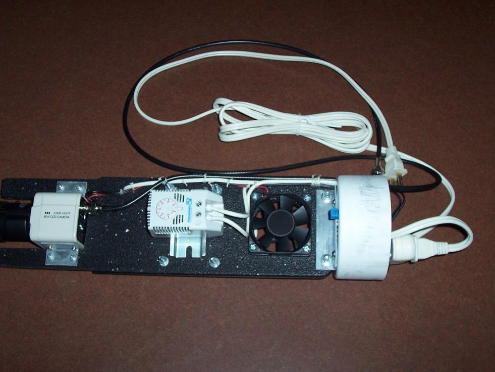
6 1 Introduction The main components of the system include a Sony black and white CCD video camera, camera lens, 12 Volt DC power adapter, resistive heaters, thermostat, DC fan, a video capture card, and a weatherproof optical dome and housing. The housing consists of PVC pipe and flanges. It is a requirement for the AllSky Camera system to be operational 24 hours a day, 365 days a year, therefore, it must be able to work in all weather conditions. The heaters, thermostat, and fan are to maintain a reasonable thermal environment for the camera system to operate within. This thermal environment is mainly to help ensure that the dome remains condensation free no matter what the moisture level is outside the housing. The camera mounting is the responsibility of the host user, since we have no control over the cameras physical mounting location. At some locations, the cameras were mounted on all-weather simulated wood. This allowed for a flat surface to mount the camera by the flanges using lag screws. Attaching the cameras to the platform made it easy to install the camera at almost any location utilizing a couple of bricks. This is a simple method that is cost effective and doesn t require drilling to the actual roof surface and can be relocated easily. (d) (e) Figure 1: Twin-camera configuration on a rooftop *NOTE: Normal Installation Does Not Require Two Cameras Below in Figures 2 and 3 are cut-away views of the camera and the environmental electronics. There are no user serviceable parts inside. There are two versions of the AllSky Camera Systems that have been distributed, they are slightly different in configuration, but are functionally the same. 2

7 Figure 2: Previous A l l s k y version 3

8 Figure 3: Current version 4
9 2 Parts List Electrical HB-710E Star Light B/W CCD Camera (1) L163VDC4P Rainbow Camera Lens (1), Fujinon YV22X14ASA Lens (1) Dale RH-50 50W resister/ heater (2) Fully Regulated 12 Volt DC 500Ma Adapter (1) Flight LT Brushless DC Fan (1) Plannenberg 30 F F Thermostat (1) Hauppauge ImpactVCB 64900, Model 188 Frame Grabber Board (1), or USB-Live2 video capture RCA interface 3 75 ohm BNC Coaxial Cable (1) 3 125V-15Amp Extension Cord(2) Housing 1 /8 X 4 1 /4 Dia. X 2 1 /8 High W/1/4 Flange Acrylic Dome, Global Plastics 4 Cap (SCH 40) (2) 17 1 /4 x 4 PVC section (SCH 40) (1) 4 closet flange (5) 4 male adapter Hub x MPT (1) Other Materials Cutting board (1) #4-40 Pan Head Machine Screws, 3 (4) #6-32 Pan Head Wood Screws, 3 /4 (4) #8-32 Pan Head Machine Screws, 1 (8) #8-32 Pan Head Machine Screw, 3 1 /2 (2) Box of 4-40 Washers (1) Box of 4-40 Lock-washers (1) 5
10 Box of 4-40 Nuts (1) 6
11 Box of 8-32 Washers (1) Box of 8-32 Lock-washers (1) Box of 8-32 Nuts (1) Reel of Weather Stripping (1) Tube of White Caulking (1) Roll of 22 AWG. Stranded Wire Red (1) Roll of 22 AWG. Stranded Wire Black (1) 10 or 12 inch Zip-Tie (6) 1 inch Heat Shrink (4) 7

12 3 Housing Step 1: Cut the 4 PVC pipe 17 1 /4 long, making sure the edge is as perpendicular as possible. See Figure 3.1. Figure 3.1: Step 1 8


13 Step 2: Using PVC Primer and Cement, prime the ends of the tube and the in- sides of the toilet flange and coupler. Then apply the cement on one end of the PVC tube and insert into the toilet flange, give it a small twist at the end to ensure a spreading of the cement and thus a good seal. Then cement the threaded coupler at the other end following the same method. Allow to dry and set. See Figure 3.2. Note: PVC Primer and Cement vapors can be irritating or harmful to some persons. A well-ventilated area, mask, and gloves should be used while applying these chemicals. See product warning label. (a) (b) Figure 3.2: Step 2 9


14 Step 3: Drill a 1 /4 hole and slot at the bottom of the flange/tube to allow the BNC cable and power cord to pass to the outside of the unit. Some filing may be needed to make the hole/slot clean and uniform. See Figure 3.3. Note: PVC dust should not be inhaled. It can be irritating or harmful to persons with allergies, a mask should be used as a precaution. (a) (b) Figure 3.3: Step 3 10


15 Step 4: Attach the acrylic dome to the 4 female coupler using clear or white RTV cement. Be cautious to not get any on the dome. Apply to the rim of the coupler, then lower the dome onto the coupler evenly. Center as well as possible. See Figure 3.4. Note: RTV Cement vapors can be irritating or harmful to some persons. A well-ventilated area, mask, and gloves should be used while applying this chemical adhesive. See product warning label. (a) (b) Figure 3.4: Step 4 11

16 Step 5: The environmental control components are held in a webbing material. This is simply a cutting board. This material was selected because it can handle the high operating temperatures without burning, melting, or deforming. Cut out the inner web to hold the environmental control components using a bandsaw or other cutting equipment as indicated in thedrawing. See Safety Warning Label. See Figure 3.5 Figure 3.5: Step 5 12


17 Step 6: Drill out the inner web to hold the enviromental control componets using a drillpress or hand drill as indicated in the drawing. See Safety Warning Label. See Figures 3.6, 3.7, 3.8. (a) (b) Figure 3.6: Step 6 13
18 14
19 15
20 Figure 3.7: Step 6 16
21 17
22 Figure 3.8: Step 6 18

23 Step 7: Gather the internal components to be mounted. Figure 3.9: Step 7 19

24 Step 8: Mount the brushless fan to the four mounting holes with the 2 hole cutout. Be sure to place the fan such that the wires are closest to the hole immediately above and to the side of the four fan mounting holes. See Figure Figure 3.10: Step 8 20

25 Step 9: Mount the bracket to hold the thermostat using two /4 machine screws with lock-washer, washer, and nut. Then snap connet the thermostat to the bracket. See Figure Figure 3.11: Step 9 21
26 Step 10: Mount the heat resistors/metal plate using four machine screws with lock-washer, washer, and nut. Then solder the wires form the thermostat to the resistors as shown. See Figure Additional wiring instructions for the resisters/thermostat are shown in Figure Figure 3.12: Step 10 22
27 Step 11: Modify the caps with a hole/slot to allow for the wires from the power supply and camera to pass and exit the bottom of the camera housing. Use the brackets as guides to make mounting holes. See Figure 3.13 Figure 3.13: Step 11 23
28 Step 12: Mount the power supply for the camera as shown in Figure 3.14 and Figure Make sure to mount so that the wire will enter the hole/slot in the cap. Secure using a zip tie. Then run the wire up the side of the web backing till you reach the area where the camera will be mounted. Cut the wires at about 15 inches long, and strip the insulation so that you can connect the camera power supply connector. Figure 3.14: Step 12 24

29 Step 13: The 120V AC/DC power adapter is attached to the inside of the close out cap using a 10 or 12 inch zip ties. The cord runs along the side with the other wires to the top area of the assembly with the fan power line. Measure the ends of the fan power cord and the AC/DC power adapter to the same length and cut the end off of the AC/DC adapter and discard. Then split the wires about 1 1 /2 inches and strip the individual wires. See Figure Figure 3.15: Step 13 Note: Wire with White Dash, and the red wire from the fan power, are to be connected in the inner screw hole on the camera power con- nector (green). The two remaining black wires connect to the outside of the camera power connector (green). Figure Cut a 13A heavy duty power cord so that it can run from the exten- sion cord up to the hole for the top and bottom resistors. Split the cord so that one end goes to the thermostat, #1 and screw it in. The other end to the top of the resistors through the hole just beside the resistor plate. Then cut from the excess wire and connect from #2 on the thermostat, to the bottom of the resistors, in the hole just above the fan. See Figure 25
30

31 Figure 3.16: Step 13 27


 Camera (b) Camera Connection (c) Resistor")
32 Step 14: Mount the camera onto the camera brackets. The edge of the connector should line up along the middle of the camera housing. Then mount the camera onto the webbing and connect the power for the fan and the camera. Connect the BNC cable for the camera output. See Figures 3.17 and (a) Camera (b) Camera Connection (c) Resistor Connection (d) Thermometer Connection Figure 3.17: Step 14 28


33 (a) (b) Figure 3.18: Step 14 24
34 (c) Figure 3.18: Step 14 24
35 Step 15: The internal components on the webbing are then inserted into the tube housing until the camera lens is just above the distortions on the dome from the bend of the flange at the bottom. Make note of its physical location. Drill a pilot hole for the small pan screw. This will hold the camera lens/internal components on the webbing at the correct height. See Figures 3.19 and Figure 3.19: Step 15 25

36 Figure 3.20: Step 15 26


37 Step 16: Insert the end cap and secure with a screw on the side. A piece of weatherstripping can be used to fill the hole made to allow the wires to pass. This will prevent water, dust, bugs, etc. from entering the camera housing. See Figure (a) (b) (c) Figure 3.21: Step 16 27
Supplemental guide on Camera Fabrication
 Supplemental guide on Camera Fabrication This document describes the steps for fabricating your camera and lighting system. 1 Materials needed Gather all your materials. You will need the small lexan sheet
MBE Mounts and Adapters
 MBE Mounts and Adapters MBE Series en Installation Guide MBE Mounts and Adapters Table of Contents en 3 Table of Contents 1 Important safety instructions 4 2 MBE Series Mounts and Adapters 6 2.1 Unpacking
INSTALLATION INSTRUCTIONS
 2015 F-150 8 MyTouch factory display 360º Vision System (Kit # AVMS-3618) DUE TO THE COMPLEXITY OF THIS KIT PROFESSIONAL INSTALLATION IS REQUIRED CALIBRATION KIT IS REQUIRED FOR FINAL PROGRAMMING -Must
Operating voltages up to 40 kvdc Operating current up to 30 Amps Advanced contact technology Silver plated and gold plated contacts available High
 Operating voltages up to 40 kvdc Operating current up to 30 Amps Advanced contact technology Silver plated and contacts available High performance insulation material General characteristics and technical
CONSOLE CONNECTOR KIT 9501 INSTALLATION INSTRUCTIONS
 CONSOLE CONNECTOR KIT 9501 INSTALLATION INSTRUCTIONS FOR USE WITH: HAMMOND Organ Models L-100, M-100 Series, M-l, M-2, M-3 LESLIE Speaker Models 760, 770, 825 KIT CONTENT Console Connector Assembly 043075
Constructing a Low-Cost Mobile Eye Tracker
 ==== Constructing a Low-Cost Mobile Eye Tracker ==== Section 1: Introduction This is a detailed set of instructions on how to build a low-cost mobile eye-tracking system from off-the-shelf components.
MCH WIRE HARNESS WITH QUICK DISCONNECT REPLACEMENT Initial Release 1/31/2013
 1. Table of Contents 1. Table of Contents Page 1 2. Remove Failed MCH-103.2 Page 1 3. Install MCH-103.2 to MCH-102NW Page 2 4. Install NC3FX-HD to MCH-103.2 Page 3 5. Install MCH-103.2 Battery Terminal
DSI-4. DMX Optically Isolated 1x4 Splitter. D Series. DSI_4 Users Manual r3.lwp copyright 2009, 2010, 2011 ELM V. T. Inc.
 DSI-4 DMX Optically Isolated 1x4 Splitter D Series 1 Table Of Contents IMPORTANT SAFEGUARDS... DSI-4 OVERVIEW... CONNECTION... PCB BLOCK DIAGRAM... SERVICING... TROUBLESHOOTING... SPECIFICATIONS... 2 3
INSPECTION TOOL. Inspection Video Camera with Color LCD Monitor. EU Environmental Protection. Model: 8802LE,8803LE. Model: 8802LE,8803LE
 INSPECTION TOOL Inspection Video Camera with Color LCD Monitor Model: 8802LE,8803LE EU Environmental Protection Waste electrical products should not be disposed of with household waste. Please recycle
Constructing a Newtonian Achromatic Refracting Telescope Dr. Larry Browning, SDSU Physics Department
 Constructing a Newtonian Achromatic Refracting Telescope Dr. Larry Browning, SDSU Physics Department These are plans to construct a Newtonian achromatic refractor telescope with a 70-mm aperture and an
ZC-OH5 TAMPER-RESISTANT INDOOR/OUTDOOR HOUSING INSTRUCTION MANUAL FOR USE WITH GANZ ZC-D5000 SERIES MINIDOME CAMERAS
 ZC-OH5 TAMPER-RESISTANT INDOOR/OUTDOOR HOUSING INSTRUCTION MANUAL FOR USE WITH GANZ ZC-D5000 SERIES MINIDOME CAMERAS Please carefully read and observe all instructions and warnings contained in this manual
B&W RearView Camera Installation & Operation
 B&W RearView Camera Installation & Operation CA52 (Camera) FOR MORE INFORMATION WWW.STRATEGICVISTA.COM BEFORE OPERATING THIS SYSTEM, PLEASE READ THIS MANUAL THOROUGHLY AND RETAIN IT FOR FUTURE REFERENCE
High Resolution Indoor Dome Camera
 INSTRUCTION MANUAL High Resolution Indoor Dome Camera Model: DBD14 Please read this manual thoroughly before use and keep it handy for future reference. -2- INTRODUCTION Features Model Features: 1/3 Sony
COMPLETE S YSTEM SHELTER
 COMPLETE S YSTEM SHELTER The weather-resistant Complete System Shelter (CSS) provides protection from the elements for system components such as the console, Solar Power Kit components, sensor interface
CONTENTS PRODUCT FEATURES... EG-2 SAFETY PRECAUTIONS... EG-2 PARTS DESCRIPTION... EG-3 INSTALLATION AND ADJUSTMENT... EG-4 SPECIFICATIONS...
 Thank you for your purchase of this product. Before operating the product, please read this instruction manual carefully to ensure proper use of the product. Please store this instruction manual in a safe
Assembly of the TACOS WAT-910BD Housing v2
 1) Circuit Diagram 2) Assembly of PCB a)tools Required. Only simple hand tools are necessary to complete the assembly of the PCB. - Soldering Iron and solder - Needle nose pliers - Wire clippers/trimmers
TECHKNOW, INC. Kiosk Order Confirmation System INSTALLATION MANUAL. Revision Date: July 11, 2012 Part # Version 3.2
 document Page 1 of 18 TECHKNOW, INC Kiosk Order Confirmation System INSTALLATION MANUAL Revision Date: July 11, 2012 Part # Version 3.2 Techknow, Inc. 393 Mayfield Road Duncan, SC 29334 www.gotechknow.com
Outdoor PTZ. Mounting on the Ceiling Using Pendant Mount. Installation Guide. For Models: I93, I94, I95, I96, KCM /12/03
 Outdoor PTZ Mounting on the Ceiling Using Pendant Mount For Models: I93, I94, I95, I96, KCM-8211 2013/12/03 Table of Contents Mounting Solutions... 3 Straight Tube Installation Procedures... 4 Step 1:
DaNI Robot Camera. User Guide V0512
 DaNI Robot Camera User Guide 60018 V0512 Materials Included Camera (includes hardware that will not be used) Modem (with power supply that will not be used) Power converter 6" Velcro strip Adhesive tab
INSTALLATION TIPS AND MAINTENANCE Manual Number
 KD6 Z-SERIES DOME Buy Ultrak Cameras & Parts @ TLS Electronics INSTALLATION TIPS AND MAINTENANCE Manual Number 518854-2960 Ultrak 4465 Coonpath Road Carroll, OH 43112 (800) 443-6680 (740) 756-9222 FAX
CM-Z2212GY. Outdoor IR Speed Dome PTZ Camera
 Outdoor IR Speed Dome PTZ Camera User s Guide CM-Z2212GY 1201-1205, Sangda Mansion, High Technology Park, SAFETY PRECAUTIONS WARNING 1. Be sure to use only the standard adapter that is specified in the
Product Specifications (for connectors), and (for headers), provides product performance requirements and test result information.
, and (for headers), provides product performance requirements and test result information.") This specification covers the requirements for application of Universal MATE N LOK Housings, Contacts, and Printed Circuit (PC) Board Headers. The housings are available in 1 through 15 circuit versions
This specification covers the requirements for application of Universal MATE N LOK Housings, Contacts, and Printed Circuit (PC) Board Headers. The housings are available in 1 through 15 circuit versions
Thanks for shopping with Improvements! Lighted Canterbury Christmas Greenery Doorway Arch Item #548443
 Thanks for shopping with Improvements! Lighted Canterbury Christmas Greenery Doorway Arch Item #548443 IMPORTANT, RETAIN FOR FUTURE REFERENCE: READ CAREFULLY. PARTS LIST: 2 Metal Plate Stands 5 Greenery
5 B&W Rear View System Camera
 5 B&W Rear View System Camera Instruction Manual MODEL: CA453 www.lorexcctv.com Copyright 2007 LOREX Technology Inc. Thank you for purchasing the Lorex 5 Black & White Rear View System Camera. This system
Installing a Power over Ethernet injector
 Installing a Power over Ethernet injector AlphaEclipse StreetSmart and RoadStar signs The instructions in this document explain how to install/replace a Power over Ethernet (PoE) injector in a StreetSmart
**** Never plug in your LED driver to AC power until all wiring is complete ****
 1 RapidLED Plug-n-Play Solderless Retrofit Kit Contents Overview... 1 Warnings Read Me First!... 1 Dimmable Driver Controller and Driver Output Current Adjustment... 2 Kit Assembly... 2 Attaching Your
V-MUX CONNECTOR and ACCESSORY SPEC
 P V-MUX V-MUXP CONNECTOR AND ACCESSORY REFERENCE SPECIFICATION August 2007 8/2/07 Page 1 of 26 V-MUX nodes for all multiplex applications: Hercules #6000-0000-03 (16) wired switch Inputs (3) wired 0-5V
Computer Temperature Interface model CTI-2. Description. Installation. Control Module
 Description The Sine Systems model CTI-2 Computer-Temperature Interface allows a computer to monitor the outside air temperature. It consists of a 2.75 x 3 x 0.75 control module with 8 screw-terminal connections.
C-POWER AC AUTOMATIC CONTROL
 Issue 1 Print 1 C-POWER AC AUTOMATIC CONTROL INSTALLATION INSTRUCTIONS & OWNER S MANUAL Model: 93 ACMC100I A Charles Industries, Ltd. All rights reserved. Printed in the United States of America. Issue
IS-DM220/IR/HB IS-DM220
 IS-DM220/IR/HB IS-DM220 Installation Guide Indoor/Outdoor Ver. 1.2 00P6NX223ZXSEA2 Table of Contents 1. Indoor Camera Installation... 3 1.1 Hard Ceiling... 3 1.2 In-Ceiling (T-Bar) Mounting... 13 1.3 4S
Solarlok PV BAR Junction Box Assemblies
 Application Specification 114-137167 8 October 2018 Rev. C Solarlok PV BAR Junction Box Assemblies Application Specification 1. Introduction This specification covers the installation of the TE Connectivity
Model: ACA400 & ACA500 Reverse Camera Installation Manual
 Model: ACA400 & ACA500 Reverse Camera Installation Manual ACA400 ACA500 FEATURES: High Resolution: 1/4 CMOS Color Camera Compact Zinc Alloy Die Cast Body Waterproof Housing 150 Degree Wide View Angle Minimum
Conductor and Cable Marking Description and Handling
 Conductor and Cable Marking Description and Handling 566 Wire marking The following markers are available: Markers for plotter marking. Markers on roll for thermal transfer printing. Remove the printed
Metham Aviation Design Limited Station Approach, Four Marks, Alton. Hants. GU34 5HN Tel +44 (0) Fax +44 (0)
 Fax +44 (0)") Contents Page General Information 1 Items Supplied 1 Variants 1 Compatibility with other products 2 Mounting the Housing assembly 2 Mounting the Camera/Lens assembly 3 Safety Precautions 4 Control Connections
Contents Page General Information 1 Items Supplied 1 Variants 1 Compatibility with other products 2 Mounting the Housing assembly 2 Mounting the Camera/Lens assembly 3 Safety Precautions 4 Control Connections
Compact Medium SOLARLOK Junction Box. Application Specification
 Application Specification 114-106003 10OCT. 2010 Rev. A2 Compact Medium SOLARLOK Junction Box Application Specification CONTENT 1. Introduction...2 2. Supporting Documents...2 2.1 Drawings...3 2.2 Product
IR Varifocal IP66 Weatherproof Cameras
 IR Varifocal IP66 Weatherproof Cameras Products: CFC6067VF, CFC6067VF2 Please read this manual before using your camera, and always follow the instructions for safety and proper use. Save this manual for
Landmark Upgrade Kit Installation Instructions
 Landmark Upgrade Kit Installation Instructions REMOVING THE LANDMARK BOARD 1 REMOVE POWER FROM UNIT. 2 Disconnect ALL board connections by removing the associated blue blocks (see Figure 1). Include the
MC-1 OPERATION MANUAL MINI CAMERA JW FISHERS MFG INC 1953 COUNTY ST. E. TAUNTON, MA USA
 MC-1 MINI CAMERA OPERATION MANUAL JW FISHERS MFG INC 1953 COUNTY ST. E. TAUNTON, MA 02718 USA (508) 822-7330; (800) 822-4744; FAX (508) 880-8949 Email: info@jwfishers.com WEB: www.jwfishers.com SPECIFICATIONS
INSTALLATION INSTRUCTIONS
 TT-40 9/0 INSTALLATION INSTRUCTIONS Original Issue Date: 9/0 Model: Automatic Transfer Switches Equipped with the Programmable Controller Market: ATS Subject: External Battery Supply Module Kit GM69-KP
LED Lighting Kit For Elara NanoEdge Fixed Frame. Installation Guide. Attention: Read this guide before assembling your screen.
 LED Lighting Kit For Elara NanoEdge Fixed Frame Installation Guide Attention: Read this guide before assembling your screen. INTRODUCTION GETTING STARTED WARNING - Sharp Edges This product may contain
EQ573 Assembly guide. EQ573 Assembly guide Main board 1. Diodes. 2. Resistors (1) 3. Test pins. 4. Ceramic capacitors.
 3. Test pins. 4. Ceramic capacitors.") EQ573 Assembly guide Safety warning The kits are main powered and use potentially lethal voltages. Under no circumstance should someone undertake the realisation of a kit unless he has full knowledge about
EQ573 Assembly guide Safety warning The kits are main powered and use potentially lethal voltages. Under no circumstance should someone undertake the realisation of a kit unless he has full knowledge about
Navigator II INstallatIoN MaNUal For static and PaN/tIlt configurations
 Navigator II Installation MANUAL For Static and Pan/Tilt Configurations Document Number: 432-0001-00-12, rev 100 FLIR Systems, Inc., 2008. All rights reserved worldwide. No parts of this manual, in whole
M215 (M215-60) Safety
 Safety") M215 QUICK INSTALL GUIDE M215 (M215-60) Safety Important Safety Information This document contains important instructions to use during installation and maintenance of the Enphase M215 Microinverter. To
M215 QUICK INSTALL GUIDE M215 (M215-60) Safety Important Safety Information This document contains important instructions to use during installation and maintenance of the Enphase M215 Microinverter. To
DirectCommand Installation RoGator Model Year Ag Leader Technology
 Note: Indented items indicate parts included in an assembly listed above Part Name/Description Part Number Quantity Direct Command Kit 4100801 1 Dual Lock 2000052-9 1 Dual Lock 2000053-9 1 Quick Reference
RCC45 ➁ Overview / /
 RCC45 ➁ Overview 010.2936 More future and modularity Integration of POF and power Guaranteed modularity Long-term investment protection Flexible cabling solution Fast and convenient installation 1 010.2721
onlinecomponents.com
 0.9 For FPC FPC connectors (0.3mm pitch) Back lock Y3B Series New FEATURES 1. Slim and low profile design (Pitch: 0.3 mm) The use of a back lock mechanism enables a 3.15 mm (with lever) low profile design.
wire guards PLAST D FUSERS FLUORESCENT LIGHTING FIXTURE PROTECTION Wire Guards / Fluorescent lighting fixture protection / Product Description:
 Wire Guards FLUORESCENT LIGHTING FIXTURE PROTECTION Wire Guard units offer an inexpensive way to protect light fixtures from excessive abuse. Wire Guard units can be fabricated to fit most shapes of light
Full HD Speed Dome IP Camera
 Full HD Speed Dome IP Camera Installation Guide Indoor / Outdoor Ver. 1.6 Preface The information given in this manual was current when published. The company reserves the right to revise and improve its
Your Global Flow Control Partner. Series 50 Valve Status Monitor Operation and Maintenance Manual
 Your Global Flow Control Partner Series 50 Valve Status Monitor Table of Contents 1. Definition of Terms... 2 2. Safety... 2 3. Storage... 3 4. Commissioning... 3 4.1. Mounting your VSM... 3 4.2. Wiring
Han PCB termination. Han-Fast Lock PCB adapter for Han DD PCB adapter for Han DDD module
 Han termination Contents Page Han-Fast Lock... 20.11 adapter for Han DD... 20.13 adapter for Han DDD module... 20.16 adapter for Han 40 A Axial module... 20.18 adapter for Han E... 20.20 adapter for Han
HD-CVI Camera User s Manual
 HD-CVI Camera User s Manual Welcome Thank you for purchasing our HD-CVI camera! This user s manual is designed to be a reference tool for your system. Please read the following safeguards and warnings
Revised: Page 1
 Brought To You By And Designed By: Revised: 2017-05-07 Page 1 Features Of The Universal PSU Kit: Fits all standard Apple II and /// Power Supply Enclosures. (all parts included, user supplies household
Model: CAM430MV Wired Multi-View Camera with License Plate / Rear Surface Mount Installation Manual Features
 Model: CAM430MV Wired Multi-View Camera with License Plate / Rear Surface Mount Installation Manual Features Fully Adjustable, Multiple Viewing Angle Smart Camera. High Resolution, 1/2 CMOS Color Camera
SITRANS F. Flowmeters SysCom Upgrade Kit IP65 (NEMA 4X) Multi-Channel. Introduction 1. Installing/Mounting 2. Hardware Installation Instructions
 Multi-Channel. Introduction 1. Installing/Mounting 2. Hardware Installation Instructions") Introduction 1 Installing/Mounting 2 SITRANS F Flowmeters SysCom Upgrade Kit IP65 (NEMA 4X) Multi-Channel Hardware Installation Instructions 1/2010 A5E02518333A Revision 04 Legal information Warning notice
Introduction 1 Installing/Mounting 2 SITRANS F Flowmeters SysCom Upgrade Kit IP65 (NEMA 4X) Multi-Channel Hardware Installation Instructions 1/2010 A5E02518333A Revision 04 Legal information Warning notice
It is very important that you read the entire presentation before you start, common mistakes are highlighted at the end. By Jim McDonnell 6/15
 It is very important that you read the entire presentation before you start, common mistakes are highlighted at the end. By Jim McDonnell 6/15 1 More Art than Science Over the years MATE has developed
Weatherproof IR Color Day/Night Cameras
 Weatherproof IR Color Day/Night Cameras Products: CFC6042IR, CFC6042IR2, CFC6042IR3, CFC6043IR, CFC6043IR2, CFC6043IR3 Please read this manual before installing and using this camera and always follow
Exterior Dot-HP User Manual
 Exterior Dot-HP User Manual Dimensions Exterior Dot-HP, clear front 34 55 177 Ø72 177 55 Ø18 Input Throughput Ø16 Exterior Dot-HP, diffuser dome front 49 33 55 177 Ø72 177 55 Ø18 Ø16 Input Throughput Exterior
BENSON VARIANTE² TUBULAR HEATER NEW FAN CONTROL/LIMIT STAT RETROFIT NATURAL GAS (G20 I 2 H), PROPANE GAS (G31 I 3 P)
, PROPANE GAS (G31 I 3 P)") Technical Bulletin BENSON VARIANTE² TUBULAR HEATER NEW FAN CONTROL/LIMIT STAT RETROFIT NATURAL GAS (G20 I 2 H), PROPANE GAS (G31 I 3 P) WARNINGS Benson equipment must be installed and maintained in accordance
Technical Bulletin BENSON VARIANTE² TUBULAR HEATER NEW FAN CONTROL/LIMIT STAT RETROFIT NATURAL GAS (G20 I 2 H), PROPANE GAS (G31 I 3 P) WARNINGS Benson equipment must be installed and maintained in accordance
Arecont Vision MegaDome 2 Installation Manual (DN Models Only)
") recont Vision MegaDome 2 Installation Manual (DN Models Only) 0 P age recont Vision MegaDome 2 Installation Manual (DN Models Only) MegaDome 2 Installation Manual (DN Models Only). recont Vision MegaDome
recont Vision MegaDome 2 Installation Manual (DN Models Only) 0 P age recont Vision MegaDome 2 Installation Manual (DN Models Only) MegaDome 2 Installation Manual (DN Models Only). recont Vision MegaDome
BreezeMAX Wi² and BreezeACCESS Wi² Quick Installation Guide
 This Quick Installation Guide is intended for experienced installers. For more information refer to the relevant sections in the BreezeMAX Wi² and BreezeACCESS Wi² System Manual. Wi² Package Content Check
COSEE-TEK ~ University of Connecticut Underwater Camera for the SeaPerch ROV
 COSEE-TEK ~ University of Connecticut Underwater Camera for the SeaPerch ROV Material List and Fabrication Instructions Version 1.0d (6/12/2016) by Kevin Joy, John Hamilton, Matthew Jewell & Ivar Babb
Mounting on the Ceiling Using Flush Mount (Face Down)
") Mounting on the Ceiling Using Flush Mount (Face Down) Installation Guide 2014/02/14 Table of Contents Safety Information... 3 Installation Procedures... 5 Step 1: Drill a Hole on the Ceiling... 5 Step
Mounting on the Ceiling Using Flush Mount (Face Down) Installation Guide 2014/02/14 Table of Contents Safety Information... 3 Installation Procedures... 5 Step 1: Drill a Hole on the Ceiling... 5 Step
ABM International, Inc. Lightning Stitch Checklist 9/13/2013
 ABM International, Inc. Lightning Stitch Checklist 9/13/2013 1) Piggy backed board assembly (1) Piggy back board assembly tested? Yes No 24v passed XB passed XA passed YB passed YA passed SAFE passed S/S
imac Intel 27" EMC 2639 Hard Drive
 imac Intel 27" EMC 2639 Hard Drive Replacement Replace the Hard Drive in your imac Intel 27" EMC 2639. Written By: Walter Galan ifixit CC BY-NC-SA www.ifixit.com Page 1 of 26 INTRODUCTION Replacing the
XDBKITS5 Bus / DB Terminal Kit (Size 5) Installation Manual DPD00116
 Installation Manual DPD00116") XDBKITS5 Bus / DB Terminal Kit (Size 5) Installation Manual DPD00116 XDBKITS5 Option Kit Installation Manual vacon 3 Installing the Bus / DB Terminal Option Kit Introduction The XDBKITS5 option kit is
XDBKITS5 Bus / DB Terminal Kit (Size 5) Installation Manual DPD00116 XDBKITS5 Option Kit Installation Manual vacon 3 Installing the Bus / DB Terminal Option Kit Introduction The XDBKITS5 option kit is
Installation Guide V290 (Color) This guide provides basic information for Unitronics LCD color touchscreen models V C30B and V T40B.
 This guide provides basic information for Unitronics LCD color touchscreen models V C30B and V T40B.") Vision OPLC Installation Guide V290 (Color) This guide provides basic information for Unitronics LCD color touchscreen models V290-19-C30B and V290-19-T40B. General Description Vision OPLCs are programmable
Vision OPLC Installation Guide V290 (Color) This guide provides basic information for Unitronics LCD color touchscreen models V290-19-C30B and V290-19-T40B. General Description Vision OPLCs are programmable
FPC connectors (0.2mm pitch) Back lock
 Back lock") 0.9 AYF21 For FPC FPC connectors (0.2mm pitch) Back lock Y2B Series New FEATURES 1. Slim and low profile design (Pitch: 0.2 mm) 0.2 mm pitch back lock design and the slim body with a 3.15 mm depth (with
0.9 AYF21 For FPC FPC connectors (0.2mm pitch) Back lock Y2B Series New FEATURES 1. Slim and low profile design (Pitch: 0.2 mm) 0.2 mm pitch back lock design and the slim body with a 3.15 mm depth (with
Wiring Best Practices
 Form Number F-2825 Issue Date Jan 3, 2018 Revision Date Jun 5, 2018 Wiring Best Practices Selecting, planning, and routing wires. Waterous Company 125 Hardman Avenue South South Saint Paul, MN 55075 (651)
PHOENIX CONTACT - 05/2007
 Ex Universal Module Carrier (Motherboard) for Accommodating 3-Wire Measuring Transducers, Intrinsically Safe, for a Maximum of 8 PI Ex Modules INTERFACE Data Sheet 103030_00_en PHOENIX CONTACT - 05/2007
ipad Mini Wi-Fi Front Facing Camera Replacement
 ipad Mini Wi-Fi Front Facing Camera Replacement Replace the Front Facing Camera in your ipad Mini Wi-Fi. Written By: Andrew Optimus Goldberg ifixit CC BY-NC-SA www.ifixit.com Page 1 of 42 INTRODUCTION
Warning Before Installation
 Warning Before Installation English Power off the Network Camera as soon as smoke or unusual odors are detected. Refer to your user's manual for the operating temperature. Contact your distributor in the
Eaton Heat Containment System (HCS) Installation Guide
 Installation Guide") Eaton Heat Containment System (HCS) Installation Guide Copyright 2011 Eaton Corporation, Worcester, MA, USA. All rights reserved. Information in this document is subject to change without notice. No part
Eaton Heat Containment System (HCS) Installation Guide Copyright 2011 Eaton Corporation, Worcester, MA, USA. All rights reserved. Information in this document is subject to change without notice. No part
F1000 User's Manual. (Version: V1.01)
") (Version: V1.01) Contents Chapter 1 Overview... 2 Chapter 2 Installation... 3 2.1 Installation guide... 3 2.1.1 Installation position... 3 2.1.2 NEMA4 standard installation... 3 2.1.3 Environment precautions...
(Version: V1.01) Contents Chapter 1 Overview... 2 Chapter 2 Installation... 3 2.1 Installation guide... 3 2.1.1 Installation position... 3 2.1.2 NEMA4 standard installation... 3 2.1.3 Environment precautions...
Float Pod Installation Manual
 Float Pod Installation Manual TABLE OF CONTENTS What to do before receiving the pod..page 3 Receiving the pod...page 5 Installing UV..Page 9 Control Box. Page 12 Intercom....Page 14 Audio.. Page 16 Pod
Adapter Kit for PanelView 1200/1200e Touch Screen Terminal Cutout
 Installation Instructions Adapter Kit for PanelView 1200/1200e Touch Screen Terminal Cutout Catalog Numbers 2711-NR5T, 2711P-RAT12E2 Topic Page About This Publication 1 Important User Information 2 About
Installation Guide. Retrofit Kit for USB Ready Intraoral Systems
 Installation Guide Retrofit Kit for USB Ready Intraoral Systems Table of Contents Wall-Mount Retrofit Kit... 2 Introduction... 2 Connecting the Articulating and Horizontal Arm Cables... 2 Installing the
Heat Containment System (HCS)
") Heat Containment System (HCS) Revision Number 1 Wright Line LLC 160 Gold Star Boulevard Worcester, MA 01606 Tel: 800-225-7348 508-852-4300 Fax: 508-365-6178 www.wrightline.com info@wrightline.com All products
Heat Containment System (HCS) Revision Number 1 Wright Line LLC 160 Gold Star Boulevard Worcester, MA 01606 Tel: 800-225-7348 508-852-4300 Fax: 508-365-6178 www.wrightline.com info@wrightline.com All products
Limanda. Technical data
 Polyamide hand held enclosures for data acquisition, MCR and automation engineering 2 sizes - 270 x 248 x 64 mm to 311 x 281 x 72 mm Large fitting area For installations and command devices mobile and
Installation Guide V290 (Color) This guide provides basic information for Unitronics LCD color touchscreen models V C30B and V T40B.
 This guide provides basic information for Unitronics LCD color touchscreen models V C30B and V T40B.") Vision OPLC Installation Guide V290 (Color) This guide provides basic information for Unitronics LCD color touchscreen models V290-19-C30B and V290-19-T40B. General Description Vision OPLCs are programmable
Vision OPLC Installation Guide V290 (Color) This guide provides basic information for Unitronics LCD color touchscreen models V290-19-C30B and V290-19-T40B. General Description Vision OPLCs are programmable
Fiber-Optic System for Sensing Under Vacuum. Vacuum chamber E39-F1V Lens Unit
 R Fiber-Optic System for Sensing Under Vacuum Omron s First Complete System for Sensing Under Vacuum H Vacuumratedto1x10-1 0 Pa S m /s max. (.5 x 10-10 torr S l/s) H The industry s First -Channel Snap-On
Mini Wall-mount Building Terminal (WBM)
") Corning Cable Systems Standard Recommended Procedure (SRP) 003-516 Issue 2, October 2004 Page 1 of 8 Contents Figure 1 WBM 1. General...1 2. Description...2 3. Precautions...2 4. Tools and Materials...3
Corning Cable Systems Standard Recommended Procedure (SRP) 003-516 Issue 2, October 2004 Page 1 of 8 Contents Figure 1 WBM 1. General...1 2. Description...2 3. Precautions...2 4. Tools and Materials...3
Insert the male, 90 angled, 2x10 connectors into the corresponding 2x10 sockets and put them in place, flat under the PCB. Solder.
 MC624 Assembly guide Safety warning The kits are main powered and use potentially lethal voltages. Under no circumstance should someone undertake the realisation of a kit unless he has full knowledge about
Dual Mount Universal Kit Aftermarket CMOS Camera with Optional Parking Gridlines Installation Instructions (Kit # )
") Please read thoroughly before starting installation and check that kit contents are complete. Items Included in Kit: Chassis Harness Power Harness with RCA connectors Camera mounted on license plate bracket
Please read thoroughly before starting installation and check that kit contents are complete. Items Included in Kit: Chassis Harness Power Harness with RCA connectors Camera mounted on license plate bracket
Arecont Vision MegaDome Installation Manual
 0 P age MegaDome Installation Manual. recont Vision MegaDome B. Mounting template C. Magnetic core D. Pack of four (4) wood screws and four (4) dry wall anchors E. One double sided hex key F. One single
SENC 150 REFERENCE MANUAL
 SENC 50 REFERENCE MANUAL SENC 50 Table of Contents / Warnings Page Introduction / Supplied items... 4 2 Preparing the mounting / Mounting information... 5 3 Encoder dimensions... 8 4 Backup spar dimensions...
Ideal protection for your electrics: häwa cable ducts
 Ideal protection for your electrics: häwa cable ducts Well Conceived The häwa group has established itself as an innovative and highly competent supplier to machinery and facility equipment companies in
Manual. Network Expansion Port 2 NEP-2. English. Brands by Navico - Leader in Marine Electronics
 Manual Network Expansion Port 2 NEP-2 English www.lowrance.com www.simrad-yachting.com Brands by Navico - Leader in Marine Electronics Disclaimer As Navico is continuously improving this product, we retain
INSTALLATION INSTRUCTIONS
 Wired Remote Controller 7 Day Programmable Ductless Systems KSACN0401AAA (High Wall Models) KSACN0501AAA (Ducted/Cassette Models) INSTALLATION INSTRUCTIONS NOTE: Read the entire instruction manual before
JAN 16 Rev B
 ANSI C136.41-2013 Rotatable Dimming Receptacles Application Specification 20 JAN 16 Rev B NOTE All numerical values are in metric units [with U.S. customary units in brackets]. Dimensions are in millimeters
Standard Buccaneer BUCCANEER FOR POWER
 IP8 rating tested at 1.05kg/sq cm (15lb/sq in) 10m depth for weeks and.8kg/sq cm (10lb/sq in) 100m depth for hours IPK, Tested in accordance with DIN 0050/Part IPkk Water and dustproof to IP8 when mated,,,,,,
2 PIECE BOARD-TO-BOARD
 2 PIECE BOARD-TO-BOARD 201-01-123 1. SPECIFICATION DISTRIBUTION No restrictions for issue 2. SCOPE This specification contains the application notes for the 9159 two part connectors. 3. PRODUCTS 10-9159
SUN2000-(33KTL, 36KTL, 40KTL)-US Quick Guide (Mounting Bracket Supplied with the SUN2000, Amphenol Helios H4)
-US Quick Guide (Mounting Bracket Supplied with the SUN2000, Amphenol Helios H4)") SUN2000-(33KTL, 36KTL, 40KTL)-US Quick Guide (Mounting Bracket Supplied with the SUN2000, Amphenol Helios H4) Issue: 03 Part Number: 31508086 Date: 2017-11-06 HUAWEI TECHNOLOGIES CO., LTD. NOTICE 1. The
SUN2000-(33KTL, 36KTL, 40KTL)-US Quick Guide (Mounting Bracket Supplied with the SUN2000, Amphenol Helios H4) Issue: 03 Part Number: 31508086 Date: 2017-11-06 HUAWEI TECHNOLOGIES CO., LTD. NOTICE 1. The
Desktop housing AZ/EL Kit V1.2 for ERC-M Instructions. Instructions
 Instructions Desktop housing AZ/EL it V1.2 for ERC-M Instructions Congratulations for buying your Desktop housing AZ/EL for ERC-M. This document will guide you through the needed steps for assembly of
CAMERA ASSEMBLY. Removal/Replacement of the Camera Box Assembly APR-CA. Install Camera Assembly. Remove Camera Assembly
 CAMERA ASSEMBLY Removal/Replacement of the Camera Box Assembly APR-CA REQUIRED TOOLS: 9/64 hex key Small flat-tip screwdriver Remove Camera Assembly camera 1. Locate the camera assembly underneath the
Sapling Converter Box
 Installation Manual Sapling Converter Box SCB-100-000-1 Version Number 1.2 Current as of March 15, 2015 The Sapling Company, Inc. (+1) 215.322.6063 P. (+1) 215.322.8498 F. 2-Wire Converter Box (SCB-100-000-1)
FUSION MS-RA70/MS-RA70N Installation Instructions
 FUSION MS-RA70/MS-RA70N Installation Instructions Important Safety Information WARNING Failure to follow these warnings and cautions could result in personal injury, damage to the vessel, or poor product
MK-101 TILE SAW OWNER S MANUAL & OPERATING INSTRUCTIONS SERIAL NUMBER:
 MK-0 TILE SAW OWNER S MANUAL & OPERATING INSTRUCTIONS CAUTION: Read all safety and operating instructions before using this equipment Enter the Serial Number of your new saw in the space below. The Serial
Wireless Video Intercom System VL-WD812BX
 Wireless Video Intercom System VL-WD812BX Specifications Model name and number Wireless Sensor Camera VL-WD812BX * The product label reads as follows: VL-WD812EX 118 mm Dimensions 290 mm 160 mm 142 mm
AIR TERMINALS: COPPER
 AIR TERMINALS: COPPER A ADAPTER TYPE B LESS ADAPTER LA TYPE A B C A B C A B C 3 8 COPPER POINTS (CLASS I ONLY) 1 2 COPPER POINTS (CLASS I OR II) 5 8 COPPER POINTS (CLASS I OR II) THE 3 8 COPPER AND ALUMINUM
Now with Picture Memory
 Intrasonic Technology, Inc. Color Video Door Phone / Intercom Installer s Manual Model No.V304KIT-R Now with Picture Memory Please read this manual carefully before the products are installed.technical