ZEISS CT Solutions Computer tomography in the plastics industry
|
|
|
- Megan Lambert
- 5 years ago
- Views:
Transcription


1 ZEISS CT Solutions Computer tomography in the plastics industry

2 When you improve your production process substantially. ZEISS CT Solutions // RELIABILITY MADE BY ZEISS 2
3 Optimization for the entire process ZEISS CT solutions for the plastics industry In order to achieve sustainable quality improvement in the manufacture of plastic parts, it is not sufficient to perform assessment at just one point in the value creation process. Every process step influences quality, beginning with development through tool manufacture, mold making and injection molding all the way to the assembly of different components. As the specific quality requirements vary from one step to the next, the quality inspection methods do as well. With its wide range of computer tomographs, software products and inspection services, ZEISS makes available solutions for all these different jobs tailored to the particular process step and embedded in the overall process. Effectively ensuring overall quality means having an eye on each individual part of the process chain and understanding how each stage is dependent on the other. Computer tomography is an inspection technology which can be networked and used along the entire process chain. It offers many advantages as compared with other measuring procedures, particularly in the plastics industry. Benefits of CT technology CTs work without destroying the workpiece. The properties of the specimen are not changed by the testing process. Nothing is hidden from CTs. Components can be captured completely, including inner structures and irregularities in the material. CTs work quickly. All selected characteristics can be evaluated together with just a single scan. A lot of information can be obtained in a comparatively short period of time. CTs capture data in 3D, meaning they provide more information than ultrasound or 2D X-ray scans. 3

4 ZEISS CT technology in the industrial process General research Product and process development Exchanging CT quality data ZEISS Xradia X-ray microscopes Material analysis P. 6-7 ZEISS METROTOM Computer tomographs Tool correction P ZEISS VoluMax Computer tomographs Resolution high-resolution detail analysis CT in research and development ZEISS high-resolution X-ray microscopes are used in the development of plastic workpieces. These microscopes can resolve the fibers of composite materials or microstructures of polymer foam in the sub-micrometer range. This enables the examination of materials under simulated external conditions such as tension or compression in order to better understand the development of defects under real-world conditions. CT for tool correction For optimal modeling, highly accurate, traceable ZEISS CT measuring machines are used which can display the dimensional stability of a workpiece completely. ZEISS REVERSE ENGINEERING software converts the deviations from the CAD model captured using CT into a corrected tool shape. This significantly accelerates the tool correction process and greatly reduces time-to-market. 4

5 Parts manufacturing Performance test P Statistical process inspection P In-line inspection P Speed inspection with high throughput CT in plastic casting For the in-line inspection of critical plastic components, fast CT systems are used which fully automate the particular inspection job and automatically identify defective components. Unlike other processes, ZEISS VoluMax CT technology allows multiple characteristics such as dimensions, wall thicknesses, burrs and pores to be tested at the same time. The integrated software ensures that inspection results are traceably documented and archived for safetyrelevant components. Moreover, ZEISS quality data management enables easy access to all inspection results at different sites and in real time, opening up new possibilities for the statistical and correlative analysis of production processes. Defects and their causes in production can be identified more quickly and resolved. 5


6 Material analysis Example: high-resolution examination of a multi-material composite material Background Fiber-reinforced plastic materials are being used more frequently in the aerospace, automotive, shipping and construction industries. The reasons for this development are the the high load capacity, stability and light weight of the fibers. For example: a compound plastic material consisting of polypropylene and glass fibers which have been poured into a polymer matrix are used for the hull of a canoe. The material offers excellent shock resistance, general stability and durability while still being lightweight. It also costs significantly less than plastics reinforced with carbon fibers, making the canoe: more resistant to water pressure and the impact resulting from hitting rocks lightweight and easy to maneuver affordable Understanding the causes of defects The interior structure of compound materials exerts a strong influence over their material properties. In order to study the characteristics of different materials, engineers must be able to make the interior structure visible and measure it. ZEISS Xradia Versa X-ray microscopes enable quantitative, high-resolution 3D analyses of the microstructure in relatively large material specimens, creating the necessary preconditions for understanding the causes of stability and the vulnerability of different material structures. The X-ray does not influence the material properties. This is the only way to examine material specimens before and after stress tests performed using tension or compression so that the changes in the microstructure are visible. 6

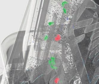
, and voids (white).")


7 A segmented 3D rending of the compound material shows glass fibers (green), polypropylene fibers (orange), and voids (white). The sub-micron 3D data shows that the distribution of glass fibers through the matrix does not appear uniform, which may have an effect on material property. The occurrence of air voids with a variety of size could also affect material strength. Courtesy of Professor Abbas S. Milani, University of British Columbia. Benefits of the ZEISS Xradia Versa System used Software used ZEISS Xradia Versa systems feature a spatial resolution in the submicrometer range, high contrast and the possibil- ZEISS Xradia 520 Versa S+S ZEISS Xradia Scout and Scan ity of maintaining high resolution at a System software great working distance, ensuring that even relatively large, in-tact specimens are imaged in detail. ORS DragonflyPro Visualization and analysis software Results High-resolution 3D visualization and subsequent analysis of composite materials can provide valuable information on porosity, fiber orientation and fiber distribution, resulting in a better understanding of core material properties. 7


8 Tool correction using ZEISS REVERSE ENGINEERING Example: housing for a tank venting valve The fastest route to the perfect tool Plastics manufacturers must meet everincreasing quality standards. Installing defective parts requires considerably more time and effort and for this reason is to be avoided. This is why quality criteria need to be observed when engineering and constructing the tool shape without making any compromises. At the same time, developers and mold makers are usually under time pressure because the time to market is one of the decisive factors in determining the success of a product launch. Influencing factors for quality The quality of plastic parts manufactured using plastic injection molding depends on many influencing factors: from the injection mold itself, the various process parameters to the type of plastic used. For example: the shrinkage behavior influences the dimensions of the injection molded part. Shrinking, in turn, depends on the other aforementioned influencing variables and cannot be predicted with great accuracy. The quality of the injection molding tool cannot be assessed by a simple measurement. Whether or not an injection mold will provide good results can only be determined by inspecting the parts manufactured using it. The tool correction process Due to the difficulty in predicting the quality of an injection mold process, tools must often be reworked multiple times until the molded parts meet the quality standards. The components must be measured completely and exactly in every correction loop, and the molding tool must then be modified in line with these results. The challenges 8


9 The color-coded display in ZEISS REVERSE ENGINEERING shows you at a glance where and by how much the component diverges from the nominal data. A shift into the blue spectrum indicates undersize whereas a shift into the red spectrum indicates oversize. when performing any correction loop are: capturing as many evenlydistributed and exact measuring points as possible transferring the measuring results to the CAD data of the tool shape ensuring an accurate fit for integrating the corrected segments into the overall shape System used ZEISS METROTOM kV/225kV Software used ZEISS METROTOM OS MOS System software ZEISS REVERSE RE ENGINEERING Reverse engineering and tool correction 9

10 Only the area marked in blue is considered for tool correction because this is decisive for fit accuracy. ZEISS METROTOM CT ZEISS offers coordinated solutions to ensure the entire tool correction process is efficient. This begins with determining dimensional stability using a ZEISS METROTOM computer tomograph, which captures all internal and external structures of the component completely. In contrast to other standard processes where the component is actually dissected and the individual segments are measured, computer tomography offers important benefits: The inspection process does not destroy the component. The amount of time required is drastically reduced. The process is reliable: there is no risk of deforming within the scope of the inspection process. The amount of information provided is greater because the entire component is captured, and not just individual sections. This can significantly reduce the number of correction loops required. The CT systems from ZEISS are also highly accurate and the results are traceable. ZEISS REVERSE ENGINEERING With ZEISS REVERSE ENGINEERING software, the CAD model of the injection molding tool can be corrected using the nominal data of a plastic component and the actual-data generated using the ZEISS METROTOM. The software corrects defective component segments in the tool data set and ensures that the selected segments fit appropriately. ZEISS REVERSE ENGINEERING detects the underlying geometries using CT volume data. The mathematically calculated surfaces are then merged 10
 are negligible.")
11 Color-coded nominal/actual comparison of the selected sub-area The nominal data of the product (yellow), the current tool shape (green) and the areas which must be corrected (white) in one display Display of the corrected and smoothed tool shape. The shape has been corrected in such a way that punctual deviations (red and blue) are negligible. to create a watertight model, meaning that there are ideally no gaps or overlaps between the surfaces. Stipulated continuity conditions can be guaranteed extremely conveniently and reliably using ZEISS REVERSE ENGINEERING. With practically no intervention, the algorithms automatically smooth the surfaces to such an extent that the transitions are as tangentially constant and curvature-constant as possible a must for optimal milling paths. In particular the automatic functions ensure continuous transitions of the corrected segments to the rest of the tool shape without crevices or kinks. Faster product manufacture Thanks to the fast and informative capture of the actual condition with the ZEISS METROTOM and efficient tool correction using ZEISS REVERSE ENGINEERING, iteration loops can be significantly reduced and shortened for tool correction while still meeting premium quality standards. Modified CAD model Tool CAD model: current tool CAD model: product Actual data: product ZEISS REVERSE ENGINEERING inverts the component deviations and transfers them to the tool data set. 11


12 Assembly inspection in product development Example: fit accuracy of a plastic screw-cap Successful model: PET bottle Bottles made from polyethylene terephthalate, also known as PET bottles, are the most commonly used beverage packaging. About one-third of all drinks worldwide are bottled in PET containers. Glass is the second most-popular material for bottles, but only makes up approximately one-sixth of the packaging currently used. The shapes of PET bottles have changed many times since their introduction in the 1980s and become increasingly diverse. Advances in production technology have made it possible to significantly reduce the weight and the quantity of materials used. Customized shapes have helped beverage producers better position their products on the market. It s the cap that counts The cap is a particularly critical area when developing a new bottle shape because it is vital for the function and safety of the PET bottle. The impermeability must be guaranteed in order to prevent both the beverage from flowing out of the bottle and germs from getting in. An additional security feature is the so-called tamper evident band which is designed to tear open or tear off when the cap is twisted. Thanks to the tamper evident band, consumers know that the bottle has not been opened after being filled. Conventional inspection If a CT system is not available, destructive testing is a standard process for inspecting the fit accuracy of the seal and the bottle. The area around the cap on a sealed bottle is embedded in resin. When cured, the resin gives 12


13 The CT data display using ZEISS NEO insights software shows if the seal is properly positioned on the bottle. the molded plastic stability, which is necessary for preventing deformations during sectioning. After being cut into many thin sections, the cross sections are checked optically to ensure defect-free contact between the cap and the bottle. Disadvantages of destructive testing The greatest drawback to the aforementioned process is the significant amount of time required. Moreover, destructive inspection is always incomplete: only those defects which appear on the cut System used ZEISS METROTOM kV/225kV Software used ZEISS METROTOM OS MOS System software ZEISS NEO insights NI Volume visualization and analysis 13

14 Different material densities are used for the color display of the bottle and cap. surfaces are spotted. Defects in the areas in between the sections remain hidden. Although the 2D cut makes it easy to identify defects, information about the spatial dimensions of the defects is lacking. It is not possible to know where and how the molding tools need to be corrected without taking further steps. This process also poses the risk that the resin warms up when hardening, deforming the plastic. This distorts the inspection result because the introduction of heat can reconnect areas which originally had not been joined. Inspections with the ZEISS METROTOM CT With a ZEISS METROTOM CT system, it is possible to examine the quality and function of the cap in its original, screwed-on state without cutting apart the bottle. Using the CT data obtained, the cap can be cross sectioned at random on the computer using ZEISS NEO insights software so that the analysis is as complete as possible. A freely rotatable, semi-transparent 3D view facilitates orientation and interpretation. The different material density of the cap and the bottle can also be used for differentiated color rendition, further simplifying analysis. The complete 3D visualization makes it possible to locate all parts on the screw thread with missing material contact so that the origin of potential leakage can be determined. Moreover, the different display formats show where and how the tool shapes of the screw top or the bottle must be corrected. Random sampling in production Highly precise inspecting and measuring computer tomographs such as the ZEISS METROTOM are not only used for 14
15 examining prototypes in product development, but also are equally suitable for performing random sampling in volume production later. The test parts are not only inspected on a purely visual basis in 3D, but also measured precisely using ZEISS CALYPSO CT. Regular random sampling and statistical evaluation using ZEISS PiWeb makes it possible to discover potential reductions in quality, e.g. caused by tool wear even as the component is being manufactured. The benefits: tool endurance can be better planned, preventing the production of rejects and the resulting subsequent costs. Information obtained using a ZEISS METROTOM in volume production can also be used later in development to design new bottles. The necessary data and analyses can be conveniently made available at different locations in the production process via ZEISS PiWeb. 15


16 Random sampling for statistical process control Example: button for a seat belt buckle Background The button on a seat belt buckle in the car must meet high quality standards to ensure that this safety-relevant component works faultlessly. Even though it is subjected to frequent mechanical stress in daily use, the button's stability over the lifetime of the car must be 100% guaranteed. Together with the other seat belt buckle components, the button also affects safety. Dimensional accuracy and mechanical stability are required for a perfectly functioning seat belt button. Quality assurance requirements Quality assurance for the button should ideally be as comprehensive as possible and should be performed immediately after its manufacture in the plastic injection mold. Otherwise, defects are only identified after the button has been installed, leading to high subsequent costs because the entire safety-relevant module must be exchanged. In a worst-case scenario, this defect can impair safety, e.g. because the seatbelt can no longer be used. Statistical process control Regular random sampling guarantees the quality of the production process because, for financial and technical reasons, it is not possible to inspect every seat belt button. Defined component dimensions are captured regularly and deviations are monitored exactly over time. Statistical analysis enables the process to be stopped at the ideal moment as well as the early identification of gradual deterioration in the process. The shape of the value progression also provides information about potential defect causes. 16
 and")


17 Best fit of CT data (blue) and CAD data (gray). Measuring values outside tolerance are marked in red. System used Software used ZEISS METROTOM kV/225kV MOS ZEISS METROTOM OS System software VGStudio Max from Volume Graphics Software for volume visualization CY ZEISS CALYPSO Analysis of standard geometries Pi ZEISS PiWeb Networked quality data management 17


18 Detail analysis of a curve form on the component using ZEISS CALYPSO CT Characteristics These features predominantly determine the quality of the button: The dimensional stability of the shape, i.e. the correspondence to the defined nominal values in the CAD model. Stability which could be potentially limited by cavities, if applicable. dimensions to be captured, the more time is required for inspection. In some cases the component must also be reclamped. Moreover, it is difficult or even impossible to measure the concealed structures using a coordinate measuring machine without destroying the component. Pores in the interior cannot be inspected. reducing both the number of rejects and the subsequent costs of defective production. Conventional inspection with a coordinate measuring machine The stability is typically inspected using a coordinate measuring machine with contact or optical sensors. The more The time required for regular inspections increases with the frequency of random inspections. However, more frequent measurements help stabilize the process and minimize tolerance deviations, 18


19 Color-coded display of dimensional stability Inspection of pores CT inspection with the ZEISS METROTOM With a ZEISS METROTOM computer tomograph, all dimensions to be captured within the scope of process control can be inspected with just a single scan. It is even possible to insert multiple components into the CT system at once and inspect them. Depending on the component size, a complete shot is also possible. Moreover, additional dimensions can be inspected at any time using the voxel data generated to perform supplementary analyses. If necessary, a color-coded display of the nominal/actual comparison provides an overview of the dimensional accuracy of the entire component. The particular strength of the ZEISS METROTOM: the measuring results are traceable and dependably meet the current metrology standards. CT material inspection In addition to dimensional stability, the ZEISS METROTOM also provides CT volume data to inspect possible pores in the material, providing information on the stability of the seatbelt button. Networked process control with ZEISS PiWeb With the ZEISS PiWeb solution, ZEISS provides a tool for statistical process control which is ideally matched to the ZEISS METROTOM. ZEISS PiWeb bundles the data captured by the ZEISS METROTOM and other measuring machines and makes them available at other sites via a secure web connection. The analyses necessary for process control are available in ZEISS PiWeb. 19


20 Inspection in volume production with large quantities Example: connector housing Background The connector housing to be inspected is combined with other components to form a plug over the course of the production process. This plug is ultimately integrated into machines and systems. Defects in the connector housing which are only identified in later process steps can lead to high additional costs. Thus quality defects in the plastic casting should be identified as quickly as possible and with 100% reliability. Characteristics Defects which can occur in the plastic casting and must be inspected are: cavities deformations deviating dimensions and wall thicknesses burrs Standard inspection methods Standard, non-destructive inspection methods such as visual inspections or gage testing only enable particular aspects of the total quality to be monitored. In order to achieve an overall picture of the object, multiple processes must be combined and the results merged. Materialography is a destructive inspection process which provides information about the interior structures. However, it requires a lot of time and effort, making it unsuitable for regular inspections. 20


21 The 3D dimensional stability can be ideally inspected using ZEISS CALYPSO CT. System used Software used ZEISS VoluMax MOS ZEISS METROTOM OS System software Pi ZEISS PiWeb Networked quality data management VOL CY Simplified user interface for ZEISS VoluMax ZEISS CALYPSO Analysis of standard geometries VGStudio Max from Volume Graphics Software for volume visualization 21


22 Inspection of pores using VGStudio Max Color-coded display of dimensional stability in ZEISS CALYPSO CT Detection of a material overhang (red) in ZEISS CALYPSO CT Benefits: ZEISS VoluMax With the ZEISS VoluMax, all required quality features can be checked on the basis of just a single scan. As a single procedure, computer tomography enables destruction-free 3D inspection of hidden structures. This largely prevents subjective evaluations or operator influences. A particular strength of the ZEISS VoluMax is the dimensional analysis. The entire component can be compared in terms of its dimensional stability using CAD data or a reference section. Deviations are, for example, comprehensively displayed using color-coding. Inspection in practice Generally a shot of injection molded parts is taken from each injection molding machine during every shift and inspected using the CT machine. In special cases, multiple random samples are taken each shift. The components are recognized automatically, and prepared inspection programs perform an automated analysis. The number of cavities in the component can be read so that a detected defect can easily be attributed to an injection mold and a manufacturing cluster. Based on the inspection results, the operators decide to what extent components in the shift are approved for additional processing. Quality data management using ZEISS PiWeb software ZEISS VoluMax automatically generates a large quantity of valuable quality data which can be documented using ZEISS PiWeb software, made available anywhere in the world and evaluated. 22


23 Virtual component cross-section using VGStudio Max For example: ZEISS PiWeb offers the option of visualizing the captured data in chronological order. Gradual changes in quality, e.g. because of wear, can be made visible and monitored. ZEISS PiWeb is also an ideal solution for the automatic and professional documentation of quality data. Stored centrally, these data can be accessed via a secure internet connection in real time and at any time, further processed and analyzed in relation to other data. The ZEISS PiWeb report shows which cavity is defective. 23
24 Using ZEISS CT technology in the industrial process General research Product and process development Exchanging CT quality data ZEISS Xradia X-ray microscopes ZEISS METROTOM Computer tomographs Analysis with ZEISS CALYPSO CT or ZEISS NEO insig Application High-resolution detail analysis Measuring and analyzing entire components Particular strengths Resolution in the submicron and nano ranges Standard-compliant and traceable precision Acceptance as per VDI/VDE 2630 Place of use Lab Measuring lab Resolution Under 700 nm (Versa), 50 nm (Ultra) μm Speed Hours Minutes 24
25 Parts manufacturing Assembly in volume production ZEISS VoluMax Computer tomographs sights Inspection with high throughput Customized product design Comprehensive project experience Fully automated evaluation In production and near production μm Seconds 25


26 ZEISS NEO insights offers comprehensive visualization possibilities in 2D and 3D as well as user-specific views and reports. Easily visualize and analyze CT volume data ZEISS NEO insights CT analysis made easy ZEISS NEO insights is the new software from ZEISS for visualizing and measuring CT volume data from ZEISS CT systems. Visual inspection, dimensional nominal/ actual comparisons and reporting results all these jobs can be performed with minimal previous knowledge thanks to the system's clear design, process-oriented user-navigation and different automatic functions. In particular, ZEISS NEO insights accelerates the work with its straight-forward operation: for many jobs, you can work directly in the image window by using the mouse instead of spending comparatively more time and effort clicking through different menus. Automatic material detection ZEISS NEO insights features comprehensive visualization options for voxel data in 2D and 3D views. A highlight is automated material separation: multiple material components are detected automatically with one click according to their density and can then be overlaid with contrasting colors. SnapViews Once found, informative visualizations can be stored in SnapViews. With just a quick click, they are available immediately or ready for use in later reports. Automatic alignment With ZEISS NEO insights, measuring in CT volume data has never been this fast or easy. Automatic alignment helps make this possible. Both the pre-alignment and fine alignment can be performed conveniently with a click, making metrology knowhow unnecessary. 26


27 Create inspection plans easily via Click&Pick Inspection plans for measuring jobs are created effortlessly with ZEISS NEO insights. Measuring elements such as circles or lines are automatically recognized by the software and can be easily selected by clicking on them. ZEISS NEO insights then suggests possible characteristics based on the context, e.g. the distance between two circle centers. All it takes is one more click to select and program the feature. Inspection plans are created with a few clicks and picks in next to no time. Integrated ZEISS PiWeb reporting ZEISS PiWeb reporting is already integrated into the software, quickly compiling professional measuring reports, including informative displays. A design module for a company-specific report design is available as an add-on. If necessary, ZEISS PiWeb reporting can be extended with comprehensive statistics functions and can be embedded in networked ZEISS PiWeb quality data management systems. Free ZEISS NEO viewer The free ZEISS NEO viewer makes the inspection results obtained with ZEISS NEO insights available to anyone. Results can be presented interactively in the original software environment. ZEISS NEO viewer also gives anyone the option of opening CT volume data and having different 2D and 3D views displayed. 27
28 ZEISS CT Solutions After sales services Manufacturing sites Sales and service companies Competence Center Sales partners Strong service Over 750 service and application technicians work for ZEISS worldwide. Thanks to our regional structure, experts and spare parts are available quickly. When it comes to service, you will benefit from our more than 90 years of experience in industrial metrology and our one-stop service offering. Well maintained optimally installed Keep your ZEISS computer tomograph ready for use and your software up to date. ZEISS offers maintenance agreements for machine service and ongoing software updates. This way you ensure that you always work optimally and productively. 28
29 Invest in knowledge ZEISS offers a wide range of training courses for both metrology in general and CT technology in particular. These include training courses for effectively using your CT machines as well as training courses for performing your own maintenance. You can also book our proven training programs for all software products from ZEISS. Our multi-step, manufacturer-neutral AUKOM training courses also teach general metrological know-how. Service program for the ZEISS VoluMax Uptime is crucial because the ZEISS VoluMax is used directly in the production environment. That is why ZEISS offers its own service program for VoluMax CT machines with three different service levels: intensive training and consultation for in-house maintenance a telephone hotline fast on-site service By providing you with intensive training for on-site maintenance and a telephone hotline, we do our best to ensure that you can help yourself should the need arise. This is the most effective method for preventing downtime. In exceptional cases where a ZEISS application technician needs to come to your site, our extensive service network ensures that we will be there quickly. We offer customized maintenance strategies based on the required machine uptime. We perform scheduled maintenance on a day that is suitable for you and in line with your shift model. 29
30 ZEISS CT Solutions CT inspection services You do not need to have a ZEISS computer tomograph to be able to benefit from ZEISS CT technology. Our measuring centers can perform different CT inspection services for you. Try out ZEISS CT solutions risk free. Dimensional measuring technology with the ZEISS METROTOM We create metrological evaluations for the interior and exterior structures of a component. That is why we use ZEISS METROTOM CT machines and ZEISS CALYPSO CT software. Our services include: Measuring standard geometries and freeform surfaces Nominal/actual geometry comparison with a color-coded 3D visualization Complete initial sample test report ZEISS METROTOM CT scans We create ZEISS METROTOM volume data as a separate service for those who use our ZEISS NEO insights, CALYPSO or REVERSE ENGINEERING software products. This ensures that various defects can be analyzed, metrological evaluations can be performed and reverse surface engineering can be created at any time. Detecting and analyzing defects with the ZEISS VoluMax On the basis of a CT scan performed with a ZEISS VoluMax, we search and examine defects in plastic and light metal components without destroying them. Our services include: Porosity and inclusion analysis Damage and failure analysis Mounting checks Assembly checks Reverse engineering with the ZEISS METROTOM Computer tomography with the ZEISS METROTOM enables you to completely and precisely capture the deviation of a workpiece from the CAD nominal data. These differential data can be used for the targeted correction of tool geometry. Our specialists will help you generate corrected CAD data for your injection molding or casting tools which are in line with your specifications and particular needs. X-ray microscopy with the ZEISS Xradia Versa From the layers of a thermal shield coating to individual fibers in carbon fiber components we visualize minuscule structures for you with ZEISS Xradia Versa X-ray microscopes. Xradia Versa machines offer a resolution from 0.7 μm and a minimal voxel size from 70 nm. This allows 3D analyses in the submicron range. The special thing about these machines: the resolution of the ZEISS Xradia Versa does not diminish, even for components with a diameter up to 300 mm and a correspondingly large working distance. 30

31 31
32 Carl Zeiss Industrielle Messtechnik GmbH Oberkochen/Germany Sales: Service: Fax: Carl Zeiss Industrial Metrology, LLC 6250 Sycamore Lane North Maple Grove, MN 55369/USA Phone: Fax: EN_60_020_162I Printed in Germany CM-CZ-IX/2016 Poo Subject to change in design and scope of delivery and as a result of ongoing technical development.
Multisensor Coordinate Measuring Machines ZEISS O-INSPECT
 Multisensor Coordinate Measuring Machines ZEISS O-INSPECT Having all the necessary options for reliable measurements. ZEISS O-INSPECT // RELIABILITY MADE BY ZEISS 2 The O-INSPECT multisensor measuring
Multisensor Coordinate Measuring Machines ZEISS O-INSPECT
 Multisensor Coordinate Measuring Machines ZEISS O-INSPECT Having all the necessary options for reliable measurements. ZEISS O-INSPECT // RELIABILITY MADE BY ZEISS 2 The O-INSPECT multisensor measuring
ZEISS O-SELECT Digital Measuring Projector
 ZEISS O-SELECT Digital Measuring Projector 2 Certainty at the push of a button. ZEISS O-SELECT // PRECISION MADE BY ZEISS 3 4 Measure reliably at the push of a button ZEISS O-SELECT makes the optical measurement
Traceable 3D X-Ray Measurements ZEISS METROTOM
 20 Traceable 3D X-Ray Measurements With a computer tomograph, you can successfully perform measuring and inspection jobs yourself with only one X-ray scan. The standard acceptance test, the precision engineering
Industrial Metrology. Multisensor Measuring Machines O-INSPECT 322/442
 Industrial Metrology Multisensor Measuring Machines O-INSPECT 322/442 The moment the answer is right in front of your eyes. This is the moment we work for. // Certainty Made By Zeiss 2 Table of Contents
HIGH RESOLUTION COMPUTED TOMOGRAPHY FOR METROLOGY
 HIGH RESOLUTION COMPUTED TOMOGRAPHY FOR METROLOGY David K. Lehmann 1, Kathleen Brockdorf 1 and Dirk Neuber 2 1 phoenix x-ray Systems + Services Inc. St. Petersburg, FL, USA 2 phoenix x-ray Systems + Services
Multi-sensor measuring technology. O-INSPECT The best of optical and contact measuring technology for true 3D measurements.
 Multi-sensor measuring technology O-INSPECT The best of optical and contact measuring technology for true 3D measurements. 2 // multifunctionality made BY CarL Zeiss The moment you realize that new requirements
Calypso the Easy Way to Create Part Programs
 Industrial Measuring Technology from Carl Zeiss Calypso the Easy Way to Create Part Programs We make it visible. Philosophy Visual Metrology TM CAD model feature characteristics Elements are selected to
Optiv CT160 Accurate measurement for every detail. Computed Tomography System
 Optiv CT160 Accurate measurement for every detail Computed Tomography System Computed Tomography CT Technology. New prospects for metrology. Computed tomography (CT), a technology with unique advantages,
The new generation of industrial computed tomography. The Desktop CT exact S
 The new generation of industrial computed tomography The Desktop CT S Volume scanning technology Innovation with a family tradition Founded in 1968, the family-owned, WEN- ZEL Metrology Group is one of
ZEISS O-SELECT Digital Measuring Projector
 ZEISS O-SELECT Digital Measuring Projector // O-SELECT MADE BY ZEISS 2 The moment you get total certainty at the push of a button. This is the moment we work for. 3 4 Reliably measure at the push of a
PWO: Faster to Finished Sheet Metal Forming Tools with Optical Metrology
 Application Note PWO: Faster to Finished Sheet Metal Forming Tools with Optical Metrology Company s place of business: Oberkirch GOM system: ATOS Triple Scan GOM software: GOM Inspect Professional Sector:
Coordinate Measuring Machines with Computed Tomography
 Always a Step Ahead with Quality Coordinate Measuring Machines with Computed Tomography Multisensor Coordinate Measuring Machines with Computed Tomography Computed Tomography in Coordinate Measuring Machines
Product Information Version 1.1. ZEISS Xradia 510 Versa Submicron X-ray Imaging: Maintain High Resolution Even at Large Working Distances
 Product Information Version 1.1 ZEISS Xradia 510 Versa Submicron X-ray Imaging: Maintain High Resolution Even at Large Working Distances Breakthrough Flexibility for 3D Submicron Imaging Achieve new levels
Roger Wende Acknowledgements: Lu McCarty, Johannes Fieres, Christof Reinhart. Volume Graphics Inc. Charlotte, NC USA Volume Graphics
 Roger Wende Acknowledgements: Lu McCarty, Johannes Fieres, Christof Reinhart Volume Graphics Inc. Charlotte, NC USA 2018 Volume Graphics VGSTUDIO MAX Modules Inline Fiber Orientation Analysis Nominal/Actual
A new Concept for High-Speed atline and inlinect for up to 100% Mass Production Process Control
 18th World Conference on Nondestructive Testing, 16-20 April 2012, Durban, South Africa A new Concept for High-Speed atline and inlinect for up to 100% Mass Production Process Control Oliver BRUNKE 1,
A new Concept for High-Speed atline and inlinect for up to 100% Mass Production Process Control
 6 th International Congress of Metrology, 06003 (203) DOI: 0.05/ metrology/20306003 C Owned by the authors, published by EDP Sciences, 203 A new Concept for High-Speed atline and inlinect for up to 00%
Seifferth GmbH: Faster Prototyping with 3D Scanners
 Application Note Seifferth GmbH: Faster Prototyping with 3D Scanners Site / Country: Spechtsbrunn, Germany GOM System: ATOS Capsule GOM Software: ATOS Professional, GOM Inspect Professional Company s field
HP-L-8.9 LASER SCANNER
 PRODUCT BROCHURE HP-L-8.9 LASER SCANNER Cost-effective laser scanning for the ROMER Absolute Arm 2 HP-L-8.9 LASER SCANNER HIGHLIGHTS MAKING LASER SCANNING ACCESSIBLE TO ALL The HP-L-8.9 is an affordable
3D X-ray Microscopy Characterization. Metal Additively Manufactured Parts. Application Note
 3D X-ray Microscopy Characterization Metal Additively Manufactured Parts Application Note 3D X-ray Microscopy Characterization Metal Additively Manufactured Parts Author: Luke Hunter ZEISS X-ray Microscopy
US foundry Bradken implements optical measuring technology
 Application Note US foundry Bradken implements optical measuring technology Location / country: Tacoma / Washington, USA GOM systems: ATOS Triple Scan, TRITOP GOM software: ATOS Professional Sector: Power
MCT225 HA Metrology CT
 MCT225 HA Metrology CT Absolute accuracy for inside metrology nikon metrology I vision beyond precision Today, manufacturers are seeking to reduce time-to-market, despite a greater variety of products
Product Information Version 2.0. ZEISS Shuttle & Find Bridge the Micro and Nano World in Materials Inspection and Analysis
 Product Information Version 2.0 ZEISS Shuttle & Find Bridge the Micro and Nano World in Materials Inspection and Analysis Bridge the Micro and Nano World in Materials Inspection and Analysis Enhance Productivity
The new generation of industrial computed tomography. The CT workstation exact M
 The new generation of industrial computed tomography The CT workstation M Volume scanning technology Innovation with a family tradition Founded in 1968, the family-owned, WEN- ZEL Metrology Group is one
Fiber Composite Material Analysis in Aerospace Using CT Data
 4th International Symposium on NDT in Aerospace 2012 - We.2.A.3 Fiber Composite Material Analysis in Aerospace Using CT Data Dr. Tobias DIERIG, Benjamin BECKER, Christof REINHART, Thomas GÜNTHER Volume
A new concept for high-speed atline and inline CT for up to 100% mass production process control allowing both 3D metrology and failure analysis
 A new concept for high-speed atline and inline CT for up to 100% mass production process control allowing both 3D metrology and failure analysis Oliver Brunke 1, Ferdinand Hansen 2, Ingo Stuke 3, Friedrich
Wieblinger Weg 92a, Heidelberg, Germany, Phone: , Fax: ;
 HOW INDUSTRIAL COMPUTER TOMOGRAPHY ACCELERATES PRODUCT DEVELOPMENT IN THE LIGHT METAL CASTING AND INJECTION MOULDING INDUSTRY. Christof REINHART 1, Christoph POLIWODA 1, Thomas GÜNTHER 1 1 Volume Graphics
See Beyond the Surface. CT Scanning Redefining Industrial Metrology
 See Beyond the Surface CT Scanning Redefining Industrial Metrology Table of Contents Table of Contents 1. What is Computed Tomography (CT) Scanning? 2. How CT Scanning Works 3. Advantages of CT Scanning
Liebherr-Aerospace: Optical Metrology from GOM Accelerates Certification Tests for New Landing Gears
 Application Note Liebherr-Aerospace: Optical Metrology from GOM Accelerates Certification Tests for New Landing Gears Location/Country: Lindenberg, Deutschland GOM system: ARAMIS GOM software: ARAMIS Professional
Application Note. Oechsler: Fewer Loops for Better Tools
 Application Note Oechsler: Fewer Loops for Better Tools Site / Country: Ansbach / Germany GOM System: ATOS Triple Scan, GOM Inspect Company s field of work: Injection molding and plastic industries Oechsler
3D scanning verifies the precision of objects printed on 3D printers
 3D scanning verifies the precision of objects printed on 3D printers Quality control: inspection of 3D printed supercar part 3D scanner: MICRON3D green 10 MPix 3D printer: Factory 2.0 Production System
Boosting the Efficiency of Wind Power Plants. Stringent Demands for Boosting the Efficiency of Wind Power Plants
 Case Study Boosting the Efficiency of Wind Power Plants By Steffen Schenk and Wolfgang Steindorf Three-dimensional measurement and analysis of rotor blades and their production facility are highly complex
VGMETROLOGY. Maximum Precision, Minimal CT Data Set Sizes
 VGMETROLOGY Maximum Precision, Minimal CT Data Set Sizes Full-featured but nonetheless easy-to-use VGMETROLOGY is made for metrologists. The Universal Metrology Solution VGMETROLOGY is made for metrologists.
Inductive sensors with IO-Link interface
 Ready for the future? Inductive sensors with IO-Link interface www.ipf-electronic.com Our sensors ensure your success 1 Industry 4.0 IO-Link: Your interface to the future The fourth industrial revolution
ZEISS TEMPAR Consistent measuring lab certification
 ZEISS TEMPAR Consistent measuring lab certification All-round monitoring of the measuring environment. ZEISS TEMPAR Measuring environment. Comprehensive monitoring so that you enjoy peace of mind. Exact
X=2000 Z=2000 X=2000 Z=1600. E0/E150 in µm L/ L/ L/ L/ L/ L/400. R0 in µm
 ZEISS MMZ M Specifications Version: November 2017 System description Type according to ISO 10360-1:2000 Moving bridge CMM Operating mode motorized / CNC Sensor mounts Fixed installation of ZEISS VAST gold
Axes 150 mm/s 150 mm/s. Y axis Z axis Vector 260 mm/s 260 mm/s. P in µm P in µm
 ZEISS PRO / Specifications Version: May 2016 System description ZEISS PRO Models Operating mode Sensor mounts Software Horizontal-arm measuring machine on X-axis guide for flush-floor installation Horizontal-arm
Advanced automated High Speed Computed Tomography for production process control. DGZfP 2011, Bremen
 DGZfP-Jahrestagung 2011 - Mo.3.B.3 Advanced automated High Speed Computed Tomography for production process control DGZfP 2011, Bremen Dr. Ingo Stuke* and Dr. Oliver Brunke** GE Sensing & Inspection Technologies
Industrial Measuring Technology from Carl Zeiss. Form, Contour and Surface. Measuring and Testing Precision from Carl Zeiss
 Industrial Measuring Technology from Carl Zeiss Form, Contour and Surface. Measuring and Testing Precision from Carl Zeiss Workshop Measuring Equipment from Carl Zeiss. The advantage of precision. Carl
Non-Destructive Failure Analysis and Measurement for Molded Devices and Complex Assemblies with X-ray CT and 3D Image Processing Techniques
 SINCE2013 Singapore International NDT Conference & Exhibition 2013, 19-20 July 2013 Non-Destructive Failure Analysis and Measurement for Molded Devices and Complex Assemblies with X-ray CT and 3D Image
ZEISS Launches New High-resolution 3D X-ray Imaging Solutions for Advanced Semiconductor Packaging Failure Analysis
 Press Release ZEISS Launches New High-resolution 3D X-ray Imaging Solutions for Advanced Semiconductor Packaging Failure Analysis New submicron and nanoscale XRM systems and new microct system provide
Advanced Computed Tomography System for the Inspection of Large Aluminium Car Bodies
 ECNDT 2006 - Th.3.4.2 Advanced Computed Tomography System for the Inspection of Large Aluminium Car Bodies M. SIMON, I. TISEANU, C. SAUERWEIN Hans WÄLISCHMILLER, Meersburg, Germany M. SINDEL, M. BRODMANN,
Sensor based adaptive laser micromachining using ultrashort pulse lasers for zero-failure manufacturing
 Sensor based adaptive laser micromachining using ultrashort pulse lasers for zero-failure manufacturing Fraunhofer Institute for Production Technology, Aachen M. Sc. Guilherme Mallmann Prof. Dr.-Ing. Robert
M-CAD
 www.envisiontec.com M-CAD Xtreme 3SP & Xede 3SP ULTRA 3SP & ULTRA 3SP High Definition Perfactory 4 Standard & Standard XL Perfactory 4 Mini & Mini XL Perfactory 3 Mini Multi Lens Perfactory Micro Desktop
μct for the Pharmaceutical Industries Innovation with Integrity From R&D to Production, Inspection and Failure Analysis Microtomography
 μct for the Pharmaceutical Industries From R&D to Production, Inspection and Failure Analysis Innovation with Integrity Microtomography Find out What's Inside Porosity and Pore Size Distribution Micro-cracks
SPECTRUM. Specifications and performance features. Industrial Metrology from Carl Zeiss. We make it visible.
 Industrial Metrology from Carl Zeiss SPECTRUM Specifications and performance features Carl Zeiss technology at an incredible value. Proven ZEISS design features Small footprint C99 controller technology
Non-destructive, High-resolution Fault Imaging for Package Failure Analysis. with 3D X-ray Microscopy. Application Note
 Non-destructive, High-resolution Fault Imaging for Package Failure Analysis with 3D X-ray Microscopy Application Note Non-destructive, High-resolution Fault Imaging for Package Failure Analysis with 3D
IntElect THE PRECISION MACHINE. Sumitomo (SHI) Demag Plastics Machinery GmbH
 Demag Plastics Machinery GmbH") IntElect THE PRECISION MACHINE Sumitomo (SHI) Demag Plastics Machinery GmbH info-dpde@dpg.com www.sumitomo-shi-demag.eu All data and information in this prospectus have been complied with great care. However,
IntElect THE PRECISION MACHINE Sumitomo (SHI) Demag Plastics Machinery GmbH info-dpde@dpg.com www.sumitomo-shi-demag.eu All data and information in this prospectus have been complied with great care. However,
Quality, Speed, Price: Now Pick Three
 Quality, Speed, Price: Now Pick Three Implementing Lean Principles is Easier with Advanced Metrology! We believe in using technology to make better parts/products faster with lower cost and higher confidence.
Boosting the Efficiency of Wind Power Plants. Stringent Demands for Boosting the Efficiency of Wind Power Plants
 Case Study Boosting the Efficiency of Wind Power Plants By Steffen Schenk and Wolfgang Steindorf Three-dimensional measurement and analysis of rotor blades and their production facility are highly complex
Japan Foundry Society, Inc. Application of Recent X-ray CT Technology to Investment Casting field. Kouichi Inagaki ICC / IHI Corporation
 Japan Foundry Society, Inc. Application of Recent X-ray CT Technology to Investment Casting field Kouichi Inagaki ICC / IHI Corporation 13 th WORLD CONFERENCE ON INVESTMENT CASTING Paper: T3 Copyright
Stereolithography Printers. Prototypes, tools and production parts with ProJet and ProX SLA 3D printers
 Stereolithography Printers Prototypes, tools and production parts with ProJet and ProX SLA 3D printers The Original, and Most Accurate, 3D Printing Technology, Fine Tuned for Even Greater Speed and Reliability
ZEISS Smartproof 5 Your Integrated Widefield Confocal Microscope for Surface Analysis in Quality Assurance and Quality Control
 Product Information Version 1.0 ZEISS Smartproof 5 Your Integrated Widefield Confocal Microscope for Surface Analysis in Quality Assurance and Quality Control Dedicated Design. Guided Workflow. Trusted
Case Study- Importing As-Molded Plastic Part Conditions into CAE tools
 1 IEI Innova Engineering 1 Park Plaza Suite 980 Irvine, California 92614 Case Study- Importing As-Molded Plastic Part Conditions into CAE tools 2 CONTENTS CONTENTS... 2 EXECUTIVE SUMMARY... 3 APPROACH...
X-rays see all X-ray computed microtomography (µct) a novel technique available at CERN for material and metrological inspection
 a novel technique available at CERN for material and metrological inspection") X-rays see all X-ray computed microtomography (µct) a novel technique available at CERN for material and metrological inspection Mariusz Jedrychowski EN/MME-MM Introduction of new technique at CERN 12/12/2017
X-rays see all X-ray computed microtomography (µct) a novel technique available at CERN for material and metrological inspection Mariusz Jedrychowski EN/MME-MM Introduction of new technique at CERN 12/12/2017
INTEGRATED ANISOTROPIC SIMULATION FOR COMPONENTS MADE FROM GLASS FIBER REINFORCED THERMOPLASTICS
 INTEGRATED ANISOTROPIC SIMULATION FOR COMPONENTS MADE FROM GLASS FIBER REINFORCED THERMOPLASTICS David Sheridan Ticona, Auburn Hills, Michigan Ulrich Mohr-Matuschek & Anton Grzeschik Ticona, Sulzbach,
Sumitomo (SHI) Demag Plastics Machinery GmbH
 Demag Plastics Machinery GmbH") Sumitomo (SHI) Demag Plastics Machinery GmbH info-dpde@dpg.com www.sumitomo-shi-demag.eu IntElect THE PRECISION MACHINE A brilliant idea stands at the beginning of every successful business deal. Committed
Sumitomo (SHI) Demag Plastics Machinery GmbH info-dpde@dpg.com www.sumitomo-shi-demag.eu IntElect THE PRECISION MACHINE A brilliant idea stands at the beginning of every successful business deal. Committed
OptoPulse EIL580. The benchmark for incremental encoders.
 OptoPulse EIL580 The benchmark for incremental encoders. OptoPulse EIL580 the established standard. OptoPulse EIL580 sets a benchmark in incremental encoders with 58 mm diameter. Cutting edge sensing technology
Guideways X axis Precision-manufactured, anodized extruded profile made of light metal. On stabilized, welded steel supports
 ZEISS MMZ E Specifications Version: November 2017 System description Type according to ISO 10360-1:2000 Gantry CMM Guideways X axis Precision-manufactured, anodized extruded profile made of light metal
New Method for Master Pattern Tool Correction Based on Computed Tomography Data and Intelligent Reverse Engineering
 New Method for Master Pattern Tool Correction Based on Computed Tomography Data and Intelligent Reverse Engineering Dominik Schmid 1, Jochen Merz 1, Jochen Hiller 2 1 Carl Zeiss Holometric Technologies
Contour LS-K Optical Surface Profiler
 Contour LS-K Optical Surface Profiler LightSpeed Focus Variation Provides High-Speed Metrology without Compromise Innovation with Integrity Optical & Stylus Metrology Deeper Understanding More Quickly
Separation of CT Nominal-Actual Comparisons for Compensation of Plastic Injection Molds
 Separation of CT Nominal-Actual Comparisons for Compensation of Plastic Injection Molds Robert Schmitt 1, Christopher Isenberg 1 1 WZL of RWTH Aachen University, Steinbachstr. 19, 52074 Aachen, Germany,
STEREOLITHOGRAPHY PRINTERS. Prototypes, tools and production parts with ProJet and ProX SLA 3D printers
 STEREOLITHOGRAPHY PRINTERS Prototypes, tools and production parts with ProJet and ProX SLA 3D printers The original, and most accurate, 3D printing technology, fine tuned for even greater speed and reliability
MarSurf. The new generation of contour measurement systems MarSurf XC 20 MarSurf XC 2
 MarSurf The new generation of contour measurement systems MarSurf XC 20 MarSurf XC 2 The new generation of contour measurement systems Ladies and Gentlemen, There is an increasing need in industrial production
View in Several Directions
 Multi-Sensor Machine Allows Two Measurements in One Setup View in Several Directions Measuring injection molded parts from the top and from the side in one setup has been impossible for medical device
Precision for People. SNAPFamily of Products
 Precision for People Family of Products The New Way to Measure Small Parts QVI measurement systems are designed to measure small, intricate parts right on the manufacturing fl oor. combines a high resolution
Polymer Micro-Optics for Today s Compact Photonic Devices
 Polymer Micro-Optics for Today s Compact Photonic Devices Lynn Dobosz - North America Sales & Business Development for the Opto-Electronic Systems business unit of the Optical Systems division of Jenoptik
MeVis-C, MeVis-Cm and MeVis-CF. High-Resolution Inspection Lenses
 MeVis-C, MeVis-Cm and MeVis-CF High-Resolution Inspection Lenses MeVis-C High-Resolution Lenses for Megapixel Cameras The LINOS MeVis-C lenses are speciically developed to be used with the highest resolution
Industrial Measuring Technology from Carl Zeiss CONTURA CONTURA G2 RDS G2 AKTIV
 Industrial Measuring Technology from Carl Zeiss CONTURA CONTURA G2 RDS G2 AKTIV Overview Introducing the next generation scanning platform. CONTURA G2 RDS and CONTURA G2 AKTIV: The CMM that brought Active
Software Form Control
 Measurement by mouse click. That's how easy workpiece inspection in the machining centre is with the help of FormControl measurement software. It makes no difference whether the workpiece has a freeform
envisiontec.com M-CAD
 envisiontec.com M-CAD Xtreme 3SP & Xede 3SP ULTRA 3SP & ULTRA 3SP HD Perfactory 4 Standard & Standard XL Perfactory 4 Mini & Mini XL Perfactory 3 Mini Multi Lens Perfactory Micro HiRes & EDU & XL Photosensitive
Reverse Engineering Tool to improve quality and efficiency of design, manufacture and analysis.
 Reverse Engineering Tool to improve quality and efficiency of design, manufacture and analysis. INTRODUCTION The Internet and technology in general has forever changed the world. This dawning of the technical
ScienceDirect. The use of Optical Methods for Leak Testing Dampers
 Available online at www.sciencedirect.com ScienceDirect Procedia Engineering 69 ( 2014 ) 788 794 24th DAAAM International Symposium on Intelligent Manufacturing and Automation, 2013 The use of Optical
3D SCANNER BUYER S GUIDE
 3D SCANNER BUYER S GUIDE WHAT YOU NEED TO CONSIDER WHEN PURCHASING A 3D SCANNER INTERESTED IN PURCHASING A 3D SCANNER BUT DON T KNOW WHERE TO START? The goal of this book is to help you define what you
Experimental accuracy assessment of different measuring sensors on workpieces with varying properties
 Experimental accuracy assessment of different measuring sensors on workpieces with varying properties Rauf Oezden 1,*, Metin Aclan 1 and Saliba Danho 2 1 Technical University of Cluj-Napoca, Ph.D. Stud.,
THE USE OF OPTICAL METHODS FOR LEAK TESTING DAMPERS
 DAAAM INTERNATIONAL SCIENTIFIC BOOK 2013 pp. 787-794 CHAPTER 47 THE USE OF OPTICAL METHODS FOR LEAK TESTING DAMPERS TOMASIAK, J. Abstract: The present paper presents the possible use of a portable structural
Toray Engineering Co., Ltd. Toray Engineering Co., Ltd. Injection Molding CAE Software. Dealer
 Injection Molding CAE Software Toray Engineering Co., Ltd. Engineering Division, CAE Software & Business Department e-mail : info@3dtimon.com http://www.3dtimon.com Head Office Nihonbashi Muromachi Building
FDM Lightweight Structures DESIGN GUIDE
 FDM Lightweight Structures THE 3D PRINTING SOLUTIONS COMPANY FDM Lightweight Structures Many aerospace and automotive applications require parts with a very high stiffness-to-weight ratio. Because of the
Contents. 1 CoreTech System Co., Ltd.
 Contents Advanced Support for Intelligent Workflow Improved User Interface 2 Expanded Gate Types.. 2 Enhanced Runner Wizard. 2 Customized Cooling Channel Templates. 3 Parameterized Mesh Generator... 3
Case Studies in the Use of Computed Tomography for Non-Destructive Testing, Inspection and Measurement
 SINCE2013 Singapore International NDT Conference & Exhibition 2013, 19-20 July 2013 Case Studies in the Use of Computed Tomography for Non-Destructive Testing, Inspection and Measurement Andrew A. MALCOLM,
3D-Analysis of Microstructures with Confocal Laser Scanning Microscopy
 3D-Analysis of Microstructures with Confocal Laser Scanning Microscopy Eckart Uhlmann, Dirk Oberschmidt Institute for Machine Tools and Factory Management (IWF), Technical University Berlin Gerald Kunath-Fandrei
CODE Product Solutions
 CODE Product Solutions Simulation Innovations Glass Fiber Reinforced Structural Components for a Group 1 Child Harold van Aken About Code Product Solutions Engineering service provider Specialised in Multiphysics
Autodesk Moldflow Adviser. Design plastics confidently.
 Autodesk Moldflow Adviser Design plastics confidently. Design Plastic Parts and Injection Molds with Confidence Discover, communicate, and resolve potential manufacturing defects earlier in the product
3D Computed Tomography (CT) Its Application to Aerospace Industry
 Its Application to Aerospace Industry") 3D Computed Tomography (CT) Its Application to Aerospace Industry C. Muralidhar, M. P. Subramanian, V. Ravi Shankar and G. Chandrasekhar Directorate of Non Destructive Evaluation, Defence Research & Development
3D Computed Tomography (CT) Its Application to Aerospace Industry C. Muralidhar, M. P. Subramanian, V. Ravi Shankar and G. Chandrasekhar Directorate of Non Destructive Evaluation, Defence Research & Development
Advanced Non-Destructive Testing by High Resolution Computed Tomography for 3D analysis of Automotive Components
 Advanced Non-Destructive Testing by High Resolution Computed Tomography for 3D analysis of Automotive Components J. Luebbehuesen GE Sensing & Inspection Technologies GmbH, phoenix x-ray, Niels-Bohr-Str.
QUICK START GUIDE ENTER AN ENVIRONMENT OF PROFESSIONAL 3D PRINTING
 QUICK START GUIDE ENTER AN ENVIRONMENT OF PROFESSIONAL 3D PRINTING MEET THE ZORTRAX M200 Zortrax M200 3D printer transforms virtual projects into three-dimensional reality. It is used to prototype and
Freeform makes it all more flexible, more customized and more fashionable
 Development of eyeglass lenses since 2000 Freeform makes it all more flexible, more customized and more fashionable Joachim Kuss, Director of Group Communications, Carl Zeiss Vision International GmbH
LightHinge+: Additively manufactured lightweight hood hinge with integrated pedestrian protection
 LightHinge+: Additively manufactured lightweight hood hinge with integrated pedestrian protection Sebastian Flügel EDAG Engineering GmbH HANNOVER MESSE 26.04.2018 EDAG Engineering GmbH: Portfolio Folie
Industrial Metrology from Carl Zeiss. Form Measuring Machines
 Industrial Metrology from Carl Zeiss Form Measuring Machines Overview Measuring Machines from Carl Zeiss For your benefit. Carl Zeiss offers a complete product line for industrial metrology. From the small
T-SCAN 3 3D DIGITIZING
 T-SCAN 3 3D DIGITIZING 2 T-SCAN 3: THE HANDHELD LASER SCANNER Launching the innovative concept of an intuitive-to-use high-precision laser scanner a few years ago, Steinbichler Optotechnik, as the first
Compact, fast, reliable. Inductive, capacitive and magnetic sensors.
 Compact, fast, reliable. Inductive, capacitive and magnetic sensors. Around the globe, automation would not be the same without non-contact inductive proximity sensors. For decades, millions of such metal-detecting
Industrial Measuring Technology from Carl Zeiss. `lkqro^ `lkqro^ do=oap do=^hqfs
 Industrial Measuring Technology from Carl Zeiss `lkqro^ `lkqro^ do=oap do=^hqfs lîéêîáéï fåíêççìåáåö=íüé=åéñí=öéåéê~íáçå ëå~ååáåö=éä~íñçêãk `lkqro^=do=oap=~åç=`lkqro^=do=^hqfsw=qüé=`jj=íü~í=äêçìöüí ^ÅíáîÉ=pÅ~ååáåÖ=íç=ëã~ää=~åÇ=ãáÇëáòÉ=ã~åìÑ~ÅíìêÉêë=Ü~ë=ÄÉÉå=êÉÇÉëáÖåÉÇ
VISOR vision sensors and the Eyesight vision systems
 VISOR vision sensors and the Eyesight vision systems Image processing made simple! VISOR Object Sensor VISOR Color VISOR Solar Sensor Eyesight Vision Systems from Page 112 from Page 62 from Page 80 from
INDUSTRIAL SYSTEM DEVELOPMENT FOR VOLUMETRIC INTEGRITY
 INDUSTRIAL SYSTEM DEVELOPMENT FOR VOLUMETRIC INTEGRITY VERIFICATION AND ANALYSIS M. L. Hsiao and J. W. Eberhard CR&D General Electric Company Schenectady, NY 12301 J. B. Ross Aircraft Engine - QTC General
Dr. Javier Santillan, San Carlos, CA
 X-ray diffraction as a tool for automated residual st ress analysis & a non-synchrotron based nanofocus x-ray computed tomography technique for materials characterization and metrology Dr. Javier Santillan,
Industrial Measuring Technology from Carl Zeiss. ECLIPSE Your first inexpensive step into production measuring technology
 Industrial Measuring Technology from Carl Zeiss ECLIPSE Your first inexpensive step into production measuring technology ECLIPSE. Economical measuring technology from Carl Zeiss. Carl Zeiss - 150 years
Coordinate Measuring Machines Catalog No. E16013
 Manual Coordinate Measuring Machine MICROCORD M Series Coordinate Measuring Machines Catalog No. E16013 2 M: More quality, right down to the very last detail. M 3 All-in-all the most economical solution
Development of Optical Coherence Tomography for the Measurement of the Surface Wrinkle of Composite Parts
 Development of Optical Coherence Tomography for the Measurement of the Surface Wrinkle of Composite Parts Yoshiharu KUZE Composite Laboratory Manufacturing Technology Research Department May 9, 2017 1
BLAZE 600M HIGH-ACCURACY BLUE LIGHT MEASUREMENT SYSTEM PRODUCT BROCHURE
 BLAZE 600M HIGH-ACCURACY BLUE LIGHT MEASUREMENT SYSTEM PRODUCT BROCHURE BLAZING SPEED, DAZZLING PERFORMANCE The BLAZE 600M portable blue light measurement system from Hexagon Manufacturing Intelligence
The NEWSLETTER Autumn 2014
 Advanced Thermal Measurements and Modelling to Improve Polymer Process Simulations By J.Sweeney,M.Babenko, G.Gonzalez, H.Ugail and B.R.Whiteside, S.Bigot, F.Lacan, H.Hirshy, P.V.Petkov, Polymer IRC, School