DVR Server Users Manual
|
|
|
- Karin Arleen Peters
- 5 years ago
- Views:
Transcription
1 DVR Server Users Manual
2 System Guide... 4 Precaution in Use... 4 Product Guide... 4 Live View... 5 Server Login... 7 Power Off... 7 On-Screen Display (OSD)... 8 View Screen... 8 Digital Zoom... 9 Video Event Log... 9 Image Control Date and Time Remote Connection Screen Capture Sensors Relays Audio Forced Recording Disk Usage Deinterlace PTZ Function Presets Pattern Tracking Group Run Search and Playback Backup and Restore Browse Snapshots E-map Web View Mobile View Remote View Client Login DVR Connection Remote Client OSD View Screen Digital Zoom Video Event Log Image Control Date and Time Screen Capture Forced Recording Sensors Relays Audio PTZ Function
3 Presets Pattern Tracking Group Run Search and Playback E-map Client Setup DVRs Groups Users System Display Server Setup Setup Menu Options Camera Settings Motion Audio Object Detection - Basic Object Detection - Advanced Event Settings Sensor Mapping Motion Mapping Motion PTZ Mapping Alarm Notification PTZ Settings Presets Pattern Tracking Group Run Recording Schedule PTZ Schedule System Settings Network Emap Users Storage Logs Import/Export Settings Frequently Asked Questions Hard Disk Requirements Mounting USB Devices Manual Partition of HDD Using Partition Manager Using Disk Mounter Resetting Video Display
4 System Guide Precaution in Use Please read all safety and operating instructions carefully before using the equipment. Power cords should be arranged safely. Do not touch with wet hands. Do not use loose plugs or damaged power cables. Do not use Benzene, Thinner or Alcohol for cleaning. It could damage the product. Do not touch exposed terminals. To switch off the system, turn the power off normally in the program and switch off the peripheral equipment. Do not insert conductive materials into the ventilation holes. Do not dismantle or modify the equipment. Do not place heavy objects on the equipment. Avoid mechanical shock while moving the equipment. When smoke is seen coming from the equipment, immediately unplug it from the power source to prevent fire or electric shock. Call the manufacturer or supplier for repairs. Product Guide These DVRs are Linux-based high-performance digital video recorders (DVRs). They are next-generation digital video security equipment replacing traditional analog time tape recorders. These DVRs are cost-effective solutions because the cost of replacing analog tapes is completely eliminated. Overall maintenance is minimized by storing data with very high compression rates using hardware MPEG-4 technology. 4

5 Live View Live View is the default mode when the DVR is first started. Under Live View, you can view videos from the cameras connected to the DVR. Search and Playback, PTZ and E-map functions of the DVR Server are accessible via Live View. 1. Display Screen Displays the videos from the cameras. 2. Date and Time Indicates date and time of the DVR server. 3. Help Opens the HELP window. 4. Mute/Unmute Mutes/Unmutes the alarm sound. 5. Lock/Unlock Locks/Unlocks the DVR application. When locked, all buttons are disabled except for the Lock/Unlock button. By default, the DVR server auto-locks when it has been idle for 60 minutes. 6. Camera Selector Displays the video of the selected camera in 1-camera layout. 7. Setup Opens Server Setup window. 8. Search Opens the Search and Playback window 9. E-map Opens E-map window. 5
6 10. PTZ Function Displays the PTZ control section. 11. Deinterlace Toggles the deinterlace option on/off. 12. Screen Layout Changes the screen layout of the live view. 13. Next Camera Displays video of next camera or cameras. (For instance, if screen layout is at 4-camera layout, the next 4 cameras will be displayed upon pressing this button.) 14. Cyclic Screen Displays videos in sequence. The cycle will follow the layout currently displayed and will skip those layouts that only show disabled cameras. 15. Full screen Displays current layout of cameras in full screen. 16. Remote Connections Indicates occurrence of a Remote Client connection. If there is a connection, the Remote Connection icon will blink. Left-clicking on the icon will display the IP address of the connected Remote Client. 17. Power Shuts down the DVR Server. 18. Sensor/Relay/Audio Selects Sensor/Relay/Audio device. 19. Image Control Controls to adjust Brightness, Contrast, Hue and Saturation. 20. Video Event Log Displays recent event logs. 21. Volume Control Shows current output volume and adjusts output volume. 22. History Opens a window to display a full listing of the event logs. 23. Record Starts forced or manual recording. The video quality and resolution will be based on current settings and the frame rate will be based on the With Event fps. 24. Screen Capture/Snapshot button Takes a snapshot of the image displayed on-screen. 25. Disk Usage Shows hard disk space consumption. 6
7 Server Login Users must login first to access all the functions of the DVR. All buttons are disabled by default. To Login 1. Click on the Unlock button on the upper right corner under Live View. 2. Enter username and password. 3. Click on the Login button or press ENTER to login. Click on the Cancel button to exit. NOTE: The factory default for the username is Admin and the password is password. This can be changed in the Users Setup. Power Off To shutdown or reboot the DVR, press the Power button. NOTE: Only authorized users can shutdown the DVR. 7
![On-Screen Display (OSD) 1. Camera Label Indicates camera label. To modify, please go to Camera Settings Setup. 2. Recording Status and Recording Type [REC] appears when there is an ongoing recording.](/docs-images/87/97347464/images/8-0.jpg "The [REC] label is color-coded based on the type of recording.")
8 On-Screen Display (OSD) 1. Camera Label Indicates camera label. To modify, please go to Camera Settings Setup. 2. Recording Status and Recording Type [REC] appears when there is an ongoing recording. The [REC] label is color-coded based on the type of recording. Types of Recording: Continuous Recording - Magenta Sensor-triggered Recording - Yellow Motion-triggered Recording - Cyan Object Detection-triggered Recording - Orange Forced Recording - Red 3. Motion Indicator A red border around the camera display indicates a detected motion. View Screen View Screens in Split Mode Switch from 1, 3, 4, 7, 9, 10, 13, or 16 channel views. Simply click on your selected layout to change layout. Next Camera and Cyclic Screen Click on the Next Camera button to switch to the next camera or cameras. Click on the Cyclic Screen button to display camera or cameras in sequence. Full Screen Mode Click the Full Screen button to display channel view in full screen. To exit full screen mode, right-click on the display screen. 8

9 Digital Zoom Digital zoom allows you to zoom up to 10x. Zoom In On one screen layout or full screen mode, left-click to zoom in. Zoom Out While zoomed-in, right-click to zoom out. Video Event Log The Video Event Log displays recent events that the DVR system has logged. It displays the type of event, timestamp, camera, camera label, and date for each event that occurred. To instantly play back the video, simply choose from the log and click on your selection. A smaller playback window will appear on your screen. 1. Play/Pause Plays / Pauses playback of the video. 2. Top Moves playback of the selected video to the first frame. 3. Skip Back Moves playback of the selected video 10 seconds back. 4. Previous Frame Moves playback to the previous frame and then pauses the playback. 5. Next Frame Moves playback to the next frame and then pauses the playback. 6. Skip Forward Moves playback of the selected video 10 seconds forward. 7. Playback Speed controls Increases/Decreases playback speed. 8. Playback Speed indicator Indicates playback speed. 9

10 Image Control Via Image Control, you can change brightness, contrast, hue, and saturation settings of the cameras currently displayed. 1. Simply click on + or to increase or decrease the selected image control option. 2. To apply the changes to all cameras, click on the Apply to All button. 3. Click the Restore Defaults button to return settings to the factory default settings. Date and Time Date and Time displays the current date and time of the system. 1. To change date and time, turn off the DVR first to reboot. 2. Hold LEFT-SHIFT key while the application is loading so that it stops the auto startup of the DVR. 3. Click on the Date and Time icon (on the desktop) to edit date and time of the system. 10

11 Remote Connection The Remote Connection indicator blinks when a Remote Client is connected to the DVR Server. Left-clicking on the icon will display the the IP(s) of the connected Remote Client(s). Screen Capture 1. To capture an image of the display screen, click on the Screen Capture button. 2. A separate window will open with a printable form containing the captured image, time stamp and camera information. 3. To print the page, click on Print. The page should be printed in landscape mode. 4. To save the captured image, click on Save. Then, save the file under the selected folder. 5. To unmount a mounted USB, click on the Unmount USB link at the bottom right corner. 6. Click on the Close button to exit the Screen Capture window. 11
12 Sensors To know which sensors are active, click on the Sensor button. Active sensors are represented as highlighted buttons. If the beep alarm notification is turned on, the system beep will also be heard. Relays To know which relays are active, click on the Relay button. Active relays are represented as highlighted buttons. Relays can be activated/deactivated by clicking on the respective relay button. Audio To know which audio is active, click on the Audio button. The active audio channel is highlighted. Only one audio channel can be on at any particular time. Speakers must be attached to the PC audio out to be able to hear live audio. The audio channel can be activated/deactivated by clicking on the respective audio button. 12
13 Forced Recording To manually start recording, click on the Record button. Click on Record button again to stop recording. Forced recording can also be scheduled through setup. NOTE: Pressing this button will stop any ongoing recording (Continuous / Sensor-triggered / Motion-triggered / Object Detection) and Forced recording will start. Disk Usage Disk Usage displays the hard disk usage. 13
14 Deinterlace Deinterlace is the process of creating a single frame from the two interlaced fields of a video frame. While interlaced, the video can look much better on a TV screen. On the contrary, on a VGA monitor, it can look rather bad. Interlace is the method of smoothening the video picture by having double the amount of frames than the video's FPS value suggests. When toggling the Deinterlace, there are several options to choose from. Adaptive Blend Blends the pixels of the video frames with motion to remove tearing. Continuous Blend Blends the pixels all the time, with or without motion. The "blurry" effect on live view will be constant. Adaptive Bob Displays odd and even lines in separate frames consecutively to remove the tearing effect on video frames with motion. May cause a "jumping" effect when Bob is not implemented when there is no motion. Continuous Bob Displays odd and even lines in separate frames consecutively all the time and will not cause the "jumping" effect since the Bob algorithm is used on all the video frames. None Deinterlace is turned off. 14
15 PTZ Function To use PTZ Function, ensure that your camera is a PTZ (Pan/Tilt/Zoom) camera. 1. Pan/Tilt buttons Pans/Tilts camera 2. PTZ Schedule Indicates that there is/are scheduled PTZ command(s) 3. Auto Pan Executes a pre-programmed sequence of PTZ commands 4. Camera Selector Selects camera 5. Zoom Control Zooms In/Zooms Out 6. Focus Control Adjusts focus 7. Iris Control Adjusts amount of light entering the camera 8. Pan/Tilt Speed Adjusts pan/tilt speed 9. Zoom Speed Adjusts zoom speed 10. Focus Speed Adjusts focus speed 11. Pattern Tracking Opens Pattern Tracking table 12. Preset Opens Preset table 13. Group Run Opens Group Run table 15
 to a Camera 1.")

16 Presets 1. Click on Preset to open Preset table. 2. Select the preset you wish to run and click Go. 3. Click on Setup to add/modify Preset settings. 4. Click Clear to delete selected preset. 5. Click on the X button to close the table. Add/Delete Preset(s) to a Camera 1. Define your preset by using the PTZ control buttons. Once you have defined the preset, click on Setup and then enter a Label for the preset and then click on OK. The new preset will be added to the list of presets. 2. To delete a preset, simply select the preset from the list and click on the Clear button. 3. Repeat Step 1 to add a new preset for the selected camera. 16
17 Pattern Tracking 1. Click on Pattern Tracking to open Pattern Tracking table. 2. Select the pattern you wish to run and click Go. 3. Click on Setup to add/modify Pattern Tracking settings. 4. Click on Clear to delete selected pattern. 5. Click on the X button to close the table. 17
. 4. Define your pattern by selecting presets from the Presets list. Simply click on the Right Arrow to add your selected preset.")
18 Add Pattern Tracking to a Camera 1. Enter your Pattern Label. 2. Enter the Dwell Time. The Dwell Time is the length of time before the camera moves to the next preset. 3. Enter a description (for the pattern). 4. Define your pattern by selecting presets from the Presets list. Simply click on the Right Arrow to add your selected preset. Once you have defined the pattern, click on Add. The new pattern will be added to the list of patterns. 5. Repeat steps 1 to 4 to add a new pattern for the selected camera. 6. Click on the Close button to exit window. 18
19 Group Run 1. Click on Group Run to open Group Run table. 2. Select the Group Run you wish to run and click Go. 3. Click on Setup to add/modify Group Run settings. 4. Click Clear to delete selected Group Run. 5. Click on the X button to close the table. 19
 that you wish to run by selecting from the drop list menu. Click on Add to save your settings. The new group run will then be added to the list.")
20 Add/Delete Group Run 1. Enter a label. 2. Enter a description for the group run. 3. Define your group run by selecting the cameras from the list. Choose the preset (of the camera) that you wish to run by selecting from the drop list menu. Click on Add to save your settings. The new group run will then be added to the list. Note: You must select at least 2 cameras in order to create a group run. 4. Repeat Steps 1 to 4 to add a new group run. 5. Click on Close to exit the window. 20

21 Search and Playback 1. Video Playback Displays recorded video. 2. Search Layouts Four layouts are available; 1, 4, 9, 16. Selecting a layout will automatically select the same number of cameras from the list. For example, clicking on the 4-layout will automatically select cameras Next Page Goes to the next set of cameras given the layout. 4. Full Screen Displays video(s) in full screen. 5. Panorama Displays the video in a sequence of frames. 6. Screen Capture Takes a snapshot of the image displayed on-screen. 7. Watermark Verification Verifies the existence and authenticity of the watermark within the video being played back. This can only be done in 1-channel layout playback. 8. Bookmark for Backup Enables the functionality to bookmark videos for backup at a later time. When this is turned on, zoom capability is turned off and clicking on a specific camera will place it in the bookmark list to mark it for backup later in the Backup and Restore module. The letter "B" will be displayed in the upper right corner signifying that the selected camera is bookmarked for backup. 9. Timeline Indicates occurrence of recorded video for selected camera based on selected filters. 10. Camera Selector Selects the camera(s). 11. Playback Controls Controls video playback. 12. Image and Volume Control Adjusts Brightness, Contrast, Hue, Saturation as well as the playback volume. 13. Event Filter Displays drop down list menu for type of event. 14. Calendar Displays the calendar. 21
22 15. Bookmark Opens the bookmark window to allow adding/deleting of a bookmark on the selected video and also to jump to the bookmarked video. 16. Backup and Restore Opens the Backup and Restore window. 17. Browse Snapshots Opens the Browse Snapshot window allowing the user to view previously taken snapshots. 18. Advanced Search Opens the Advanced Search window if the playback is in one camera layout. 19. Help Opens the Help window. 20. Close Closes the Search and Playback window. 22

23 Playback Recordings 1. To search and playback recorded video, choose the type of event from the Event Filter drop list menu. You may choose from ALL, CONTINUOUS, SENSOR, MOTION, OBJECT DETECTION, EVENT, or FORCED RECORDING. 2. Select the date from the Calendar. You may specify the month, year and date. 3. Select the camera or cameras by clicking on the camera number. (Simply click on the camera number again to unselect camera.) If you see colored bars on the Timeline, that means there are recordings for that particular period. 4. On the Timeline for Hours, double click on the colored bars to view recorded videos for that particular hour. If there are any, recorded videos will appear as colored bars in the Timeline for Minutes. 5. Click on the colored bars in the Minutes section to play back the recordings starting from the minute selected. Playback will continue to other recordings until the end of the selected day. 6. To zoom in (available in single playback mode), simply left-click on the playback screen. Right-click to zoom out. NOTE: Sensor-triggered recordings appear as yellow bars, motion-triggered recordings appear as blue bars, object detection-triggered recordings appear as orange bars, continuous recordings appear as purple bars and forced recordings appear as red bars. Recordings with audio appear with a green band at the bottom of the bar. Playback Controls 1. Play/Pause Plays / Pauses playback of the video 2. Top Moves playback of the selected video to the first frame 3. Skip Back Moves playback of the selected video 10 seconds back 4. Next Frame Moves playback to the next frame and then pauses the playback 5. Skip Forward Moves playback of the selected video 10 seconds forward 6. Playback Speed indicator Indicates playback speed 7. Playback Speed controls Increases/Decreases playback speed 23

24 Advanced Search 1. Search Type Select if advanced search will be for motion or object detection. 2. Camera Displays the camera currently selected for the advanced search. 3. Start Date/Time Indicates the start for the date and time range for the advanced search. 4. End Date/Time Indicates end for the date and time range for the advanced search. 5. Event Type Filter Filters the type of recording to include in the advanced search. 6. Selected Region Click and drag on the image to select the region which is to be searched. 7. Clear Clears the currently selected region. 8. Search Starts the search based on the parameter settings. 9. Bookmark Bookmarks the currently selected entry in the search result list. 10. Reset Resets the search result list back to blank. 11. Search Result List Displays the results of the advanced search. Double clicking on an entry in the list will automatically start playing it in the Search and Playback window. 24

25 Backup and Restore 1. Backup Tab Lists all video files that are ready for backup. 2. Restore Tab Lists all video files that can be restored. 3. Bookmarks Tab Lists all video files that have been previously bookmarked for backup. 4. Recording Type Filter Displays a drop down list menu of recording types that can be used to filter the video files displayed. 5. Show Backed-up Files Option to display previously backed up files in the selection list. By default. files that have already been backed up will no longer be displayed in the list. 6. Check List Options A selection option that allows the user to select a start date, end date and a list of cameras. Clicking the Check List button will then automatically select the appropriate video files for backup in the selection list. 7. Logs Indicates backup and restore logs as well as status information. 8. Add Adds the selected folder to the Destination Directory 9. Remove Removes the selected folder in the Destination Directory 10. Backup Options Options to convert files to AVI format and to include the Backup Viewer installer for Windows. 11. Backup Starts the backup process. 12. Clear Logs Clears all backup and restore logs. 13. Close Closes the Backup and Restore window. 14. Eject CD Ejects the CD from the CD tray. 15. Unmount USB Unmounts a mounted USB. 25
26 Backup Files 1. To backup recorded videos, click on the Backup and Restore button in Search and Playback. 2. Click on the Backup tab. 3. Select the files that you wish to backup from the list indicated by Video Files to Backup, by marking on the checkboxes. You may also filter files by choosing from the drop down list menu. Possible options are ALL, CONTINUOUS, SENSOR, MOTION, EVENT, or FORCED RECORDING. 4. Select the destination directory. To backup to CD or DVD, select cdrecorder. When cdrecorder is selected as the destination directory, folders cannot be created when the Create Folder button is clicked. The Create Folder button will only work when backing up to a USB or a hard disk. 5. To convert files to avi format, choose the "Convert backup files from mp4 to avi format" option. A dialog box will pop up, confirming such request. Click on OK to convert backup files to.avi format. NOTE: Video files converted to avi format cannot be restored and are not marked with the status of "backed up". 6. And then click on the Backup button to backup. NOTE: Backup of videos currently does not support saving to multi-session CDs/DVDs. To backup successfully, a new CDR/DVDR or blank CDRW/DVDRW must be used. 26

27 1. Backup Tab Lists all video files that are ready for backup. 2. Restore Tab Lists all video files that can be restored. 3. Bookmarks Tab Lists all video files that have been previously bookmarked for backup. 4. File System Lists the file system drives. 5. Destination Directory Lists the directories available for backup and restore. 6. Restore File List Lists all the files that will be restored. 7. Add - Adds selected folder to the Destination Directory. 8. Remove Removes selected folder in the Destination Directory. 9. Logs Indicates backup and restore logs as well as status information. 10. Clear Logs Clears all backup and restore logs. 11. Add File(s) Adds file(s) to Restore File list. 12. Remove File(s) Removes file(s) from the Restore File list. 13. Restore Restores all files in the Restore File list. 14. Close Closes the Backup and Restore window. 15. Eject CD Ejects the CD from the CD tray. 16. Unmount USB Unmounts a mounted USB. 27
28 Restore Files 1. To restore videos, click on the Backup and Restore button in Search and Playback. 2. Click on the Restore tab. 3. From your File System, select the files that you wish to restore from the list. Add the files that you wish to restore by clicking on the Add button. 4. And then click on the Restore button to restore the video. NOTE: Retrieving/Restoring files changes the status of the selected file(s) from offline to online, thereby making this/these file(s) available for playback. 28

29 1. Backup Tab Lists all video files that are ready for backup. 2. Restore Tab Lists all video files that can be restored. 3. Bookmarks Tab Lists all video files that have been previously bookmarked for backup. 4. Files for Backup Displays the list of files that have previously been bookmarked for backup while doing Search and Playback. 5. Add Adds the selected folder to the Destination Directory 6. Remove Removes the selected folder in the Destination Directory 7. Backup options Options to convert files to AVI format and to include the Backup Viewer installer for Windows. 8. Logs Indicates backup and restore logs as well as status information. 9. Backup Starts the backup process. 10. Clear Logs Clears all backup and restore logs. 11. Close Closes the Backup and Restore window. 12. Remove File Removes the selected video file from the Files for Backup list. 13. Clear List Clears all video files from the Files for Backup list. 14. Unmount USB Unmounts a mounted USB. 29

30 Browse Snapshots 1. Directory Paths Displays a list of available paths for easy navigation. 2. Snapshot Listing Lists the available snapshots (JPEGs only) in the current directory. 3. Image Preview Displays a preview of the snapshot selected. 4. Add Adds the current folder to the Directory Paths. 5. Remove Removes the selected folder from the Directory Paths. 6. Selected Snapshots Displays the list of selected snapshots for copying. 7. Add to List Add the selected snapshot to the list for copying. 8. Remove Removes the selected snapshot from the list for copying. 9. Unmount USB Unmounts a mounted USB. 10. Save File Save the selected snapshots to the current directory. 11. Delete File Delete the selected snapshot from the system. 12. Close Close the window. 30

31 E-map The E-map shows a geographical representation of where the cameras, sensors and relays are located. 1. Click on the E-map button to go to E-map. 2. To view the current video for a particular camera, simply double click on the camera on the map. A pop-up screen showing the video for that particular camera will appear. 3. To search for a particular camera, sensor or relay, simply double-click on the device under the devices section and the map containing the device will automatically be displayed. NOTE: Please refer to Setup for more information on how to configure the E-map function. 1. E-map Display Displays the current selected E-map 2. Maps Displays the list of available maps 3. Devices Displays list of cameras, sensors and relays 4. Help Opens the Help window 5. Close Closes E-map window 31
32 Web View Web View offers connection to the DVR Server via a web browser. 1. Ensure that Internet Explorer (IE) can download unsigned ActiveX controls. For MPEG Stream connection, ActiveX plug-ins must be downloaded. For low bandwidth networks such as dial-up or ADSL connections, there is no need to install ActiveX plug-ins. You may go directly to Step 2. For Firefox users, logging in will automatically go to the JPEG Stream option since Firefox does not support ActiveX controls. For IE: Open IE, click TOOLS, click Internet Options. Click the Security tab. Click on Custom Level. Enable download unsigned ActiveX control and click OK. Click Apply and select OK to exit. 2. Enter the IP address of the DVR Server on the address bar. 3. Enter username and password. 4. Click on Login button or press Enter to login or Cancel button to exit. 32
 5.")
33 1. Display Screen - Shows videos from the cameras 2. PTZ Function - Shows functions for PTZ control 3. Screen Layout - Displays screen layout of the selected layout 4. Next Camera - Displays video of next camera or cameras. (For instance, if screen layout is at 4-split screen, the next 4 cameras will be displayed upon pressing this button.) 5. Cyclic Screen - Displays videos in sequence in full screen, with a delay of 3 seconds in between each camera 6. Sensor/Relay/Camera - Selects Sensor/Relay/Camera device 7. Screen Capture/Snapshot button - Takes a snapshot of the image displayed on-screen 8. Date and Time - Indicates date and time 9. Close - Closes Web View window 33
34 Mobile View Mobile View allows users to access the DVR with the use of a mobile phone that is 3G-enabled. To access the live streaming video of the DVR through a mobile phone, follow the steps below. *Note: The DVR server must have a global IP address in order to view the video stream through a mobile phone. 1. Start the mobile phone's web browser. 2. Open the following URL in the browser: server global IP address]/mobile/ 3. A login screen will appear where a valid username, password and the camera to view is required. 4. Once these are validated, the browser will return a link to display the live video for that camera. 5. Open the link to start streaming the live video. The links to the streaming video expire after 15 minutes unless refreshed by a new connection. 34

35 Remote View Gain remote access to the DVR Server by installing the Remote Client (available in the CD Installer) on the PC that you wish to have remote connection to the DVR. 1. Date and Time - Displays date and time of DVR Server 2. Remote View - Displays the remote live view. 3. Screen Layout Changes the screen layout of the live view. 4. Next Camera Displays video of next camera or cameras. (For instance, if screen layout is at 4-camera layout, the next 4 cameras will be displayed upon pressing this button.) 5. Cyclic Screen Displays videos in sequence. The cycle will follow the layout currently displayed and will skip those layouts that only show disabled cameras. 6. Full screen Displays current layout of cameras in full screen. 7. Frame Limit Limits the number of frames sent from the server. This is useful if there is a bandwidth or CPU limitation for the remote user. 8. Talk Click and hold to enable 2-way communication with server. A microphone must be attached and the MIC boost option turned off. To talk, click and hold the button. Audio playback will be paused during this period. Once released, audio playback will be continued. To hear the audio from the server, the appropriate audio channel must be selected. 9. Live View Streaming Displays the video stream of what is currently being displayed on the DVR server. This is similar to the JPEG stream connection except that the video format is MPEG4. It also follows some of the limitations of the JPEG streaming but a configurable frame rate, picture quality and resolution makes the live view streaming more flexible in meeting the demands of users with low bandwidth. This feature is only available for servers with at least dual core processors. 35
36 10. Sensor/Relay/Audio Selects Sensor/Relay/Audio device. 11. Image Control Controls to adjust Brightness, Contrast, Hue and Saturation. 12. Video Event Log Displays recent event logs. 13. Record Starts forced or manual recording. 14. Screen Capture/Snapshot button Takes a snapshot of the image displayed on-screen. 15. DVR Selection Selects the active DVR when in group mode. The relay and sensor display will depend on the active server selected in this dropdown. 16. PTZ Function Shows functions for PTZ control 17. DVRs Displays list of available DVR connections. Once connected it shows the list of cameras for the DVR server. Left-clicking on a camera displays the selected camera and sets the layout to 1-camera. 18. Connect/Disconnect button Connect or disconnects to the selected DVR Server 19. FPS and KBps When connected the number bytes received as well as the FPS received and displayed are shown. 20. Client Setup Opens the Client Setup window. 21. DVR Setup Opens the DVR Server Setup window. 22. Search and Playback Opens the Search and Playback window. 23. Emap Opens the Emap window. 24. Help Opens the Help window. 25. Mute Mutes/Unmutes the alarm sound. 26. Minimize Minimizes the Remote Client application. 27. Close Closes the Remote Client application. 36

37 Client Login 1. To login, click on the DVR Client on your desktop to open the Remote Client. 2. Enter username and password. 3. Click on the Login button or press ENTER to login. Click on the Cancel button to exit. NOTE: The factory default for username is Admin and for password is password respectively. You can change the default username and password once you are logged in. 37

38 DVR Connection To connect to a DVR 1. Select a DVR from the list. 2. Click the Connect button or double-click on the DVR Name to connect to the selected DVR. 3. A menu will appear with the option for JPEG Stream connection or MPEG Stream connection. Select the desired connection and the application will then connect to the DVR Server. JPEG Stream Connection This type of connection displays the video as motion-jpeg images. The bandwidth it uses to display one camera or 16 cameras is the same but it comes with certain limitations. The limitations to this type of connection are: Display is at most 5 frames per second Live streaming audio is not available Remote recording is not available Zoom while in full screen mode is not available Image enhancements functionality is not available Video display will pause when someone is performing Search and Playback or Setup on the server The layout of the display is dependent on what is currently set on the server; changing the layout on the server will also change the displayed layout on the remote client MPEG Stream Connection This type of connection streams MPEG4 video to the Remote Client. The frames per second display follows what is set on the server just as long as the bandwidth can accommodate it. Once connected, the number of frames received, frames displayed and the size of data received per second are displayed for the user. 38
![Remote Client OSD 1. Camera label Indicates camera label. To modify, please go to Setup. 2. Recording Status and Recording Type [REC] appears when there is an ongoing recording.](/docs-images/87/97347464/images/39-0.jpg "The [REC] label is color-coded based on the type of recording.")
39 Remote Client OSD 1. Camera label Indicates camera label. To modify, please go to Setup. 2. Recording Status and Recording Type [REC] appears when there is an ongoing recording. The [REC] label is color-coded based on the type of recording. Types of Recording: Continuous Recording - Magenta Sensor-triggered Recording - Yellow Motion-triggered Recording - Cyan Object Detection-triggered Recording - Orange Forced Recording - Red 3. Motion Indicator A red border around the camera display indicates a detected motion. View Screen View Screens in Split Mode Switch from 1, 4, 9, 16, 36 or 64 channel views. Simply click on your selected layout to change the layout. Next Camera and Cyclic Screen Click on the Next Camera button to switch to the next camera or cameras. Click on the Cyclic Screen button to display camera or cameras in sequence. Full Screen Mode To display in full screen, click the Full Screen button. To exit full screen mode, right-click on the display screen. 39

40 Digital Zoom Digital zoom allows you to zoom up to 2x. Zoom In On one screen layout or full screen mode, left-click to zoom in. Zoom Out While zoomed-in, left-click again to zoom out. Video Event Log The Video Event Log displays all events that the DVR system has logged. It displays the DVR Name, DVR s IP address, date and time, and the event that occurred. To instantly play back the video, simply choose from the log and double-click on your selection. A smaller playback window will appear on your screen. This functionality is only available for PC-based DVRs. 1. Play Plays playback of the video 2. Pause Pauses playback of the video 3. Previous Frame Moves playback to the previous frame and then pauses the playback 4. Next Frame Moves playback to the next frame and then pauses the playback 5. Skip Back Moves playback of the selected video 10 seconds back 6. Skip Forward Moves playback of the selected video 10 seconds forward 7. Playback Speed indicator Indicates playback speed 8. Playback Speed controls Increases/Decreases playback speed 40
41 Image Control Via Image Control, you can change brightness, contrast, hue, and saturation settings of the cameras currently displayed. 1. Simply click on + or to increase or decrease the selected image control option on the cameras currently displayed. 2. To apply the changes to all cameras, click on the Apply to All button. 3. Click the Restore Defaults button to return settings to the factory default settings for all cameras. Date and Time Date and Time displays the current date and time of the DVR Server the Remote Client is connected to. 41

42 Screen Capture 1. To capture an image of the display screen, click on the Screen Capture button. 2. A separate window will open with a printable form containing the captured image, time stamp and camera information. 3. To print the captured image, click on Print. 4. To save the captured image, click on Save and then select the folder to save to. 5. Click on the Close button to exit the Screen Capture window. Forced Recording To manually start recording, click on the Record button. Click on Record button again to stop recording. 42
43 Sensors To know which sensors are active, click on the Sensor button. Active sensors are represented as highlighted buttons. If the beep alarm notification is turned on, the system beep will also be heard. Relays To know which relays are active, click on the Relay button. Active relays are represented as highlighted buttons. Relays can be activated/deactivated by clicking on the respective relay button. Audio To know which audio is active, click on the Audio button. The active audio channel is highlighted. Only one audio channel can be on at any particular time. Only the audio channels of the video currently being displayed are available. The audio channel can be activated/deactivated by clicking on the respective audio button. 43

44 PTZ Function To use PTZ Function, ensure that your camera is a PTZ (Pan/Tilt/Zoom) camera. 1. Pan/Tilt buttons Pans/Tilts camera 2. PTZ Schedule Indicates that there is/are scheduled PTZ command(s) 3. Auto Pan Executes a pre-programmed sequence of PTZ commands 4. Camera Selector Selects camera 5. Zoom Control Zooms In/Zooms Out 6. Focus Control Adjusts focus 7. Iris Control Adjusts amount of light entering the camera 8. Pan/Tilt Speed Adjusts pan/tilt speed 9. Zoom Speed Adjusts zoom speed 10. Focus Speed Adjusts focus speed 11. Pattern Tracking Opens Pattern Tracking table 12. Preset Opens Preset table 13. Group Run Opens Group Run table 44

45 Presets To display the list of presets available, simply click on the Preset button. Presets are predefined locations where a PTZ camera has been focused. To set up a preset, refer to the Server Setup > Presets section. 1. Select a preset from the list. 2. Click on the Go button to run the selected preset. 45
46 Pattern Tracking To display the list of pattern tracking available, simply click on the Pattern Tracking button. Pattern tracking is a functionality which allows the DVR Server to control a PTZ camera to move from one predefined preset to another. It can be used to have a PTZ camera scan a room or area by automatically focusing on different locations in a sequential manner. For details on setting up a pattern tracking sequence, refer to the Server Setup > Pattern Tracking section. 1. Select a pattern from the list. 2. Click on the Go button to run the selected pattern. 46
47 Group Run To display the list of group runs available, simply click on the Group Run button. A group run is a functionality that allows the DVR Server to simultaneously redirect the focus of several PTZ cameras to specific areas. To set up a group run, refer to the Setup > Group Run section. 1. Select a group run from the list. 2. Click on the Go button to run the selected group run. 47

48 Search and Playback 1. Calendar Displays calendar 2. Camera Selector Selects camera(s) 3. Timeline Indicates occurrence of recorded video for selected camera based on selected filters 4. Event Filter Displays drop list menu for type of event 5. Video Playback Displays recorded video 6. Playback Controls Controls video playback 7. Full Screen Displays video in full screen 8. Record button Starts forced or manual recording (Video quality and resolution will be based on existing recording settings; frame rate is based on settings for Event-FPS.) 9. Screen Capture/Snapshot button Takes a snapshot of the image displayed on-screen 10. Close Closes Search and Playback window 11. DVR Selection Selects the active DVR when in group mode 48

49 Playback Recordings 1. To search and playback recorded video, choose the type of event from the Event Filter drop list menu. You may choose from ALL, CONTINUOUS, SENSOR, MOTION, EVENT, or FORCED RECORDING. 2. Select the date from the Calendar. You may specify the month, year and date. 3. Select the camera by clicking on the camera number. (Simply click on the camera number again to unselect camera.) If you see colored bars on the Timeline, that means there are recordings for that particular period. 4. On the Timeline for Hours, double click on the colored bars to view recorded videos for that particular hour. If there are any, recorded videos will appear as colored bars in the Timeline for Minutes. 5. Click on the colored bars in the Minutes section to play back the recordings starting from the minute selected. Playback will continue to other recordings until the end of the selected hour. 6. Initially, the recorded video is displayed in its original size (CIF, 1/2 D1 or D1). Left-clicking once will maximize the display on the playback area. The second left-click will zoom in to the selected area. Another left-click will then bring the display back to its original size. NOTE: Sensor-triggered recordings appear as yellow bars, motion-triggered recordings appear as blue bars, continuous recordings appear as purple bars and forced recordings appear as red bars. Playback Recordings 1. Play/Pause Plays / Pauses playback of the video 2. Skip Back Moves playback of the selected video 10 seconds back 3. Previous Frame Moves playback to the previous frame and then pauses the playback 4. Next Frame Moves playback to the next frame and then pauses the playback 5. Skip Forward Moves playback of the selected video 10 seconds forward 6. Playback Speed indicator Indicates playback speed 7. Playback Speed controls Increases/Decreases playback speed 49

50 E-map The E-map shows a geographical representation of where the cameras, sensors and relays are located. This functionality is only available for PC-based DVRs. 1. Under the Remote View Screen, click on the E-map button to go to E-map. 2. To view the current video for a particular camera, simply double click on the camera on the map. A pop-up screen showing the video for that particular camera will appear. 3. To search for a particular camera, sensor or relay, simply double-click on the device under the devices section and the map containing the device will automatically be displayed. NOTE: Please refer to Setup for more information on how to configure the E-map function. 1. E-map Display Displays the current selected E-map 2. Maps Displays the list of available maps 3. Cycle Maps Displays maps in sequence, with a delay of 5 seconds in between each map 4. Devices Displays list of cameras, sensors and relays 5. E-map Setup Opens E-map Setup. Refer to DVR Setup>System>Emap for more information on setting up your E-map settings. 6. Close Closes E-map window 7. DVR Selection Selects the active DVR when in group mode 50
51 Client Setup In order to use the Remote Client to access DVR servers, you will first have to setup the connection settings of the DVR servers that you want to connect to. This can be done by clicking on the Client Setup button once logged in to the Remote Client application. From the Client Setup, you can manage the DVR servers that are available to connect to, the users who can log in to the application and other settings modifiable by the user. 51

.")
52 DVRs Add a DVR 1. Click on the DVR tab. 2. Click on Add button. 3. Enter the DVR Name. 4. For the connection type, pick from static IP, hostname or DDNS. Using the DDNS option requires registration to the DDNS server. Place the DDNS server followed by a slash and the client account name provided (i.e. The DVR Name should also be set to the DVR Name set in the DVR server. 5. Place the username and password for the server and then click on the OK button. 52


53 Groups Add a Group 1. Click on the Group tab. 2. Click on Add button. 3. Enter the Group Name. 4. Select from the dropdown the DVR you want to add to the group. 5. Select from camera list the camera you wish to add to the group and click on the Add button. 6. To remove a camera from the group listing, select the camera from the group listing and click on the Delete button. 7. Click on the OK button to save the group settings. 53
, Full Name and Password. Confirm your password. 4.")
54 Users Add a User 1. Under Client Setup, click on the User tab. 2. Click on Add button. 3. Enter User (User ID or username), Full Name and Password. Confirm your password. 4. Click on OK button. 54

55 System Set Alarm Sound 1. To enable Alarm Sound, select System. This will enable the system beep. 2. Or select None if otherwise. 3. Click the OK button to save your settings. Set Recording Path 1. Under the File System box, click on Browse to open the search dialog box. 2. Search for the folder where you want your video recordings to be stored/saved. 3. Once you are done, click on OK to set the path. 4. Click the OK button to save your settings. Set Cycle Dwell Time 1. To set how long the camera waits before moving on to the next camera in cycle mode, place the desired number in seconds in the text box under the label Cycle Dwell Time. 2. Click the OK button to save your settings. 55

56 Display On Screen Display Options The user has the option to display various OSD labels on the video whether in Live View or in Search and Playback. OSD modifications will take effect even while connected to a DVR. 56

57 Server Setup The DVR Server Setup can be accessed either through the DVR Server itself or through the Remote Client application. NOTE: Use of the DVR Setup function is only allowed if current user s Login ID is authorized for this function. User Login 1. Enter the username and password. 2. Click on the Login button or press ENTER to login. Click on the Cancel button to exit. NOTE: The factory default for username is Admin and for password is password respectively. You can change the default username and password once you are logged in. 57
58 Setup Menu Options The server setup is divided into several sections each with it's own sub-menu. Camera This section contains the setup for the camera settings - labels, Frames Per Second (FPS), video size, video quality, buffers, motion zones, audio quality and object detection settings. Event This section contains the setup for sensor and relay related settings - sensor-relay mappings, sensor-camera mappings, sensor-ptz mappings, motion-relay mappings and alarm notification details on these events. PTZ This section contains setup information on PTZ cameras - protocols, general communication settings, presets, pattern tracking and group run. Schedules This section contains the setup for scheduled tasks - video recording and PTZ schedules. System This section contains a variety of settings - Initial overlay screen, video signal, server settings, DDNS settings, network configuration, emap, user setup, storage setup and the server logs. Import/Export This section only contains the function for importing a previous dvr settings or exporting the current setting for backup. Close The X on the upper right-hand area of the menu is the close button for the DVR server setup. Only upon clicking this button will the DVR server reload the changes in the settings that have been applied in the setup. 58

59 Camera Settings 1. Unique settings checkbox Indicates whether unique settings are used per camera or otherwise. If checked, unique settings are used per camera. To have all cameras use the same settings, keep this option unchecked and modify the settings in Camera All. 2. Secret Status Indicates whether the secret option is on or off for the camera. If checked, it means that the video for that camera will not be displayed in live view. Any recording, however, will still take place and the recording status will still appear as an On-Screen Display (OSD). 3. Enabled Status Indicates whether the camera is enabled or otherwise. If checked, it means that the camera is enabled. 4. MPEG4 Date/Time OSD Indicates whether the date and time will be embedded on the MPEG4 recording as an OSD. The date/time OSD will be visible only on the modules that use the MPEG4 data (playback, remote client and setup). 5. Label Indicates the camera label that will be displayed as an OSD in live view. 6. Sequence Determines the display location of the specific camera in live view. 7. Normal FPS Indicates the frames per second the video will be recorded/streamed at during normal circumstances when continuous recording is set. 8. With Event FPS Indicates the frames per second the video will be recorded/streamed at when an event occurs. Events comprise of a sensor being triggered, motion being detected or when forced recording is turned on. 9. Video Quality Indicates the quality the video will be recorded/streamed at. Five settings are available from Very High, High, Medium, Low, Very Low. With higher video quality, though, the file size of the recording will also increase. 10. Video Size Indicates the resolution size the video will be recorded/streamed at. For NTSC the settings are 720x480 (D1), 720x240 (1/2 D1) and 360x240 (CIF). For PAL the settings are 720x576 (D1), 720x288 (1/2 D1) and 360x288 (CIF). The higher the resolution, the bigger the size in the recording file size. There is a limitation on the combination of settings for the Video 59
60 Size in conjunction with the With Event FPS. Please see the note below for more details on this. 11. Pre-Record Buffer Indicates how long in seconds the recording will be buffered at the start of an event recording. 12. Post-Record Buffer Indicates how long in seconds the recording will be buffered at the end of an event recording. 13. Restore Defaults Restores the default settings. 14. Apply Saves the settings. Important Note: Cameras 1 to 16 has a maximum total capture speed of 480/400 fps for NTSC/PAL. This allows 30/25 fps per camera at CIF resolution. With larger video sizes, the set fps becomes equivalent to double, for 1/2 D1 resolution, and quadruple, for D1 resolution, when calculating the total capture speed for 16 cameras. Because of this, the maximum fps that can be set when cameras 1 to 16 are all set to D1 is 7.5 fps for NTSC. 60

61 Motion Set Detection Zone(s) 1. To set detection zone(s), first select the camera desired by choosing from the Camera drop down list menu. Choosing the Camera All option will allow the settings to apply to all cameras. 2. Click on the Select button. Click and drag the mouse pointer on any area on the Video Display. Simply release the mouse button when the selection is done. The detection zone(s) are marked with a white grid. Repeat step 2 when necessary, to add more detection zone(s). 3. To erase selection, click on the Erase button and drag the mouse pointer over the detection zone(s) that are to be erased. 4. To clear all selected detection zone(s), click on the Clear All button. 5. Drag or click on the sensitivity bar to set how sensitive the motion detection should be. 6. To apply settings, click on the Apply button. 1. Camera Displays a drop down list menu listing all cameras. Choose "All" to update all cameras with the same settings. 2. Select Enables selection of detection zone(s). 3. Erase Enables the deletion of detection zone(s). 4. Select All Selects the entire video area as a zone. 5. Clear All Clears all detection zones. 6. Apply Saves the settings. 7. Sensitivity Shows the current motion sensitivity setting for the specific camera. The higher the value, the more sensitive the motion detection. 8. Video Display Shows current view of selected camera as well as the selected detection zones. Movement detected within the zones will highlight the specific area within the selected zone. 61

62 Audio 1. Audio Output volume control Shows current output volume. Click on the + or - to increase or decrease the output volume respectively. This setting does not affect the audio volume set in the live view and is used only when testing the audio during setup. 2. Unique settings checkbox Indicates whether unique settings are used per audio or otherwise. If checked, unique settings are used per audio. To have all audio use the same settings, keep this option unchecked and modify the settings in Audio All. 3. Enabled status Indicates whether the audio is enabled or otherwise. If checked, it means that the audio is enabled. If the audio is disabled, the input gain controls will not be displayed. If there are no audio inputs, disable the audio to save on storage space. 4. Input Gain volume control Shows current input gain volume. Click on the + or - to increase or decrease the input gain of the specific audio. 5. Test Audio Tests current input gain settings. NOTE: Test button will only appear if setup is done on the server. You will need speakers attached to the audio out of the PC to be able to hear the live audio. 6. Restore Defaults Restores the default settings. 7. Apply Saves the settings. 62

63 Object Detection - Basic Set Object Detection Zone(s) 1. To set object detection zone(s), first select the camera desired by choosing from the Camera drop down list menu. Choosing the Camera All option will allow the settings to apply to all cameras. 2. Click and drag the mouse pointer on any area on the Video Display. Simply release the mouse button when the selection is done. The object detection zone(s) are marked with a white grid. Repeat step 2 when necessary, to add more detection zone(s). Zones should not overlap one another and there is a maximum of eight (8) zones per camera. 3. To clear all selected detection zone(s), click on the Clear All button. 4. To apply settings, click on the Apply button. 1. Camera Displays a drop down list menu listing all cameras. Choose "All" to update all cameras with the same settings. 2. Select All Selects the entire video area as one zone. 3. Clear All Clears all object detection zones. 4. Apply Saves the settings. 5. Video Display Shows current view of selected camera as well as the selected detection zones. 6. Minimum Object Size Displays the minimum object size to be detected within the selected zone(s). The size detected follows the area size indicated and not the shape displayed. For customized object size, select Other and place the desired block size. NOTE: This setup page will only appear if the server specifications meet the minimum hardware requirements of at least a Dual Core processor and 1GB memory. 63

64 Object Detection - Advanced Objection detection depends on two pictures - the background picture and the foreground picture. The difference between the two pictures are the missing objects, new objects or displaced objects. These advanced settings allows the user to tweak the performance of the feature. 1. Unique settings checkbox Indicates whether unique settings are used per camera or otherwise. If checked, unique settings are used per camera. To have all cameras use the same settings, keep this option unchecked and modify the settings in Camera All. 2. Activity Level This parameter describes the general activity of the scenario. The options are High. Medium and Low. Examples of scenes with high activity are mall entrances, train stations and airport lobbies. High activity scenes can be described as scenes that are always or almost always in a state of flux - people come and go fairly quickly. Examples of scenes with low activity are jewelry stores, secluded areas and stock rooms. Low activity scenes can be described as scenes that people don't visit often. 3. Movement Movement is a parameter that describes how people in a scene moves. The options are Very Fast, Fast, Medium, Slow and Very Slow. Examples of scenes where people move quickly are corridors, mall entrances and fire exits. In these scenarios, people don't stay at one place for even a small amount of time - they move continuously. On the other end, scenes where people don't move too much are conference rooms, restaurants and private offices. In these places, people tend to stay where they are for some time. Note, however, that it is possible for people to keep still for a long time that the computer may consider them an inanimate object. Anywhere in between are scenes like people waiting for an elevator, people lining up to buy tickets and people waiting for a green line so they can cross the street. The important consideration here is how long people tend to stay where they are. Below is a rough 64
65 equivalence: Very fast would be constantly moving. Fast would be "pausing for a moment". Medium would be "staying in place for a few seconds". Slow would be "staying in place for a couple of seconds". Very slow would be "keeping still for about half a minute". 4. Sensitivity This parameter controls how the computer responds to changes in scenes. The options are High, Medium and Low. 5. Video Clarity This parameter controls how the computer handles video noise. Select what most closely describes the video clarity. The options are Excellent, Good, Fair, Poor and Noisy. 6. Restore Defaults Restores the default settings. 7. Apply Saves the settings. NOTE: This setup page will only appear if the server specifications meet the minimum hardware requirements of at least a Dual Core processor and 1GB memory. 65

66 Event Settings 1. Sensor/Relay Operation Indicates if sensors and relays operation are enabled or disabled. If there are none attached to the DVR Server, make sure that this is set to disabled. To be able to map sensors to relays or cameras and cameras to relays, this option has to be enabled. 2. Relay Reset Time Indicates the time in seconds it takes for relays to reset back to normal mode if the reset mode is time-based. 3. Restore Defaults Restores the default settings. 4. Apply Saves the settings. 66

67 Sensor Mapping Map Sensors 1. To map the sensors to cameras, simply select Cameras in the Sensor Mapping option. Click on the grid to place an "O" to mark the sensor-camera mapping. Once a sensor has been mapped to a camera, this means that when that particular sensor is triggered, such as when a smoke detector detects smoke, the camera which is mapped to that sensor will start to record. NOTE: You can map one sensor to more than one camera and vice versa. When applied, this means that when a smoke detector or an infrared proximity sensor are triggered, the camera that is mapped to these sensors will start to record. 2. To map the sensors to relays, simply select Relays in the Sensor Mapping option. Click on the grid to place a mapping. Depending on what reset mode is selected in the drop down list menu, the appropriate mark will appear on the grid. A "T" for time-based reset mode, an "S" for sensor synchronized reset mode or an "X" for manual reset mode. Once a sensor has been mapped to a relay, this means that when that particular sensor is triggered, such as when a smoke sensor detects smoke, the relay which is mapped to that sensor will either open or close. NOTE: You can map one sensor to more than one relay and vice versa. When applied, this means that when a smoke detector or an infrared proximity sensor are triggered, the relay that is mapped to these sensors will open or close, i.e. light will turn on. 3. To apply settings, click on the Apply button. 1. Sensor Mapping Indicates what sensor mapping is currently displayed; mapping to cameras or relays. The active mapping is also indicated above the mapping area. 2. Reset Mode Indicates the reset mode for sensor-relay mappings. This is disabled when the sensor mapping is set to cameras. The reset mode options are Time, Sensor Synchronized 67
68 and Manual. Time-based reset mode follows the relay reset time set in the General Event Settings. Sensor synchronized reset mode follows the status of the sensor. If the sensor turns off, then so does the relay. Manual reset mode means the relay will not reset back to normal unless manually reset. 3. Normal State Indicates what the normal state of the sensor is set to. If the sensor is normally set to ON, then click on the normal state to set it on. 4. Map PTZ Indicates if the sensor will be mapped to a PTZ action when it is triggered. If this is unchecked, then the PTZ On, PTZ Off and Dwell Time options are also disabled. 5. PTZ On Displays a drop down list menu of available PTZ presets and group runs that can be called when the sensor is triggered. 6. PTZ Off Displays a drop down list menu of available PTZ presets and group runs that can be called when the Dwell Time length has been reached. 7. Dwell Time Indicates the length in seconds on how long the PTZ will remain in the PTZ On position before going to the PTZ Off position. 8. Mapping Indicates the mapping that have been set. For sensor-camera mappings, an "O" signifies that there is a mapping there. For sensor-relay mappings, a "T" signifies a mapping that has a time-based relay reset mode. An "S" signifies a mapping that has a sensor-synchronized relay reset mode. An "X" signifies a mapping that has a manual relay reset mode. 9. Restore Defaults Restores the default settings. 10. Apply Saves the settings. 68

69 Motion Mapping Map Camera Motion 1. To map the cameras to relays, click on the grid to place a mapping. Depending on what reset mode is selected in the drop down list menu, the appropriate mark will appear on the grid. A "T" for time-based reset mode, an "M" for motion synchronized reset mode or an "X" for manual reset mode. Once a camera has been mapped to a relay, this means that when that particular camera detects motion, the relay which is mapped to that camera will either open or close. NOTE: You can map one camera to more than one relay and vice versa. When applied, this means that when motion is detected in any of the cameras, the relay that is mapped to these cameras will open or close, i.e. light will turn on. 2. To apply settings, click on the Apply button. 1. Reset Mode Indicates the reset mode for camera-relay mappings. The reset mode options are Time, Motion Synchronized and Manual. Time-based reset mode follows the relay reset time set in the General Event Settings. Motion synchronized reset mode follows the status of the camera. If the camera no longer detects motion, then the relay turns off. Manual reset mode means the relay will not reset back to normal unless manually reset. 2. Mapping Indicates the mapping that have been set. For camera-relay mappings, a "T" signifies a mapping that has a time-based relay reset mode. An "M" signifies a mapping that has a motion-synchronized relay reset mode. An "X" signifies a mapping that has a manual relay reset mode. 69
70 3. Restore Defaults Restores the default settings. 4. Apply Saves the settings. 70

71 Motion PTZ Mapping Set Motion PTZ Mapping Zone(s) 1. To set detection zone(s), first select the camera desired by choosing from the Camera drop down list menu. 2. Select one of the nine (9) mappings. Select the preset you want associated to the mapping and also how long the PTZ will stay in that preset when triggered. 3. Click and drag the mouse pointer on any area on the Video Display. Simply release the mouse button when the selection is done. The detection zone(s) are marked with the color of the chosen mapping. Repeat step 2 and 3 when necessary, to add more zone(s). 4. To clear all selected detection zone(s), click on the Clear All button. 5. To apply settings, click on the Apply button. 1. Camera Displays a drop down list menu listing all cameras. 2. Clear All Clears all mapping zones. 3. Apply Saves the settings. 4. Video Display Shows current view of selected camera as well as the mapped zones. 5. Selected Mapping Displays the currently selected mapping. 6. Preset Display the selected preset for the specific mapping. When motion is detected in the specific zone mapping, this preset will be triggered. 7. Home Preset Displays the selected preset for the specific home mapping. After the dwell time passes, this preset will be triggered. 8. Dwell Time Shows how long the PTZ will stay focused in the area when triggered. 71

72 Alarm Notification 1. Port Displays a drop down list menu for port settings. 2. Data Bit Displays a drop down list menu for data bit settings. 3. Baud Rate Displays a drop down list menu for baud rate settings. 4. Parity Displays a drop down list menu for parity settings. 5. Stop Bit Displays a drop down list menu for stop bit settings. 6. Unique settings checkbox Indicates whether unique settings are used per camera or otherwise. If checked, unique settings are used per camera. To have all cameras use the same settings, keep this option unchecked and modify the settings in Camera All. 7. Motion Border Indicates whether the motion border alarm notification is enabled or not. If checked, it means that a red border will appear around the video in live view if motion is detected. 8. Object Detection Mask Indicates whether the object detection mask alarm notification is enabled or not. If checked, it means that a transparent blue mask will appear around the area in live view where a new object was placed or where an object was removed. 9. Emap Indicates whether the e-map alarm notification is enabled or not. If checked, it means that when motion is detected for that camera the camera icon in the emap will then blink. 10. Beep Enables/disables the system beep when an alarm is triggered Indicates whether alarm notification is enabled or not. If checked, it means that an notification will be sent to the specified along with a jpeg screenshot attached to it when an alarm occurs for that specific camera Address Displays address used for the alarm notification. 13. SMS Indicates whether SMS alarm notification is enabled or not. If checked, it means that an SMS notification will be sent to the specified cell number when an alarm occurs for that specific camera. 14. Cell No. Displays cell phone number used for the SMS alarm notification. The country code must be included in the entry. 72
73 15. and SMS Notification Delay Sets the minimum delay between and SMS notifications. If an alarm is triggered for a specific camera and an or an SMS notification has already been sent, an or SMS will not be sent again for that camera if the same type of alarm is triggered within the delay period. This is to prevent the spamming of and SMS notifications. 16. Restore Defaults Restores the default settings. 17. Apply Saves the settings. 73

74 PTZ Settings 1. Port Displays a drop down list menu for port settings. 2. Data Bit Displays a drop down list menu for data bit settings. 3. Baud Rate Displays a drop down list menu for baud rate settings. 4. Parity Displays a drop down list menu for parity settings. 5. Stop Bit Displays a drop down list menu for stop bit settings. 6. With PTZ Indicates the PTZ status of the camera. If checked, it means that the camera is equipped with PTZ capabilities. 7. Protocol Displays a drop down list menu for supported PTZ protocols. Currently supported PTZ protocols include Pelco D, Pelco P, Merit Li-Lin, DynaColor (DSCP), and VISCA SNC-R225. NOTE: VISCA SNC-R225 protocol does not have autopan or iris functionality. It also only supports 6 preset positions. 8. Address Indicates the address to be used for the PTZ camera. This address has to be unique across all enabled PTZ cameras. 9. Motion Tracking Indicates if motion tracking for the PTZ is enabled. If enabled, the PTZ will track motion that is detected within it's field of vision. 10. Tracking Speed Displays the tracking speed the PTZ camera uses to track detected motion. Increasing or decreasing this value will allow the user to calibrate the PTZ to track more smoothly. 11. PTZ Speed Displays the movement speed of the PTZ camera. Increasing or decreasing this 74
75 value will allow the user to calibrate the PTZ to track more smoothly. 12. Home Preset Displays the preset location that the PTZ camera will move back to once a certain length of inactivity is reached. 13. Inactivity Reset Displays how long in seconds the PTZ camera will wait before going back to the home preset location once there is no more motion activity detected. 14. Restore Defaults Restores the default settings. 15. Apply Saves the settings. 75
 from the preset list. 4. PTZ Control buttons Controls the PTZ camera. 5.")
76 Presets Presets are predefined locations where a PTZ camera has been focused. 1. Camera Displays a drop down list menu of cameras. Only PTZ cameras enabled in PTZ Settings will be displayed. 2. Preset List Displays the list of presets that have been defined for the selected camera. 3. Delete Deletes a selected preset(s) from the preset list. 4. PTZ Control buttons Controls the PTZ camera. 5. Add Adds the current PTZ position as a preset for the current camera. The name of the preset will be based on what is placed in the text box. 6. Video Display Displays the camera view. 76

77 Pattern Tracking Pattern tracking is a functionality which allows the DVR Server to control a PTZ camera to move from one predefined preset to another. It can be used to have a PTZ camera scan a room or area by automatically focusing on different locations in a sequential manner. 1. Camera Displays a drop down list menu of cameras. Only PTZ cameras enabled in PTZ Settings will be displayed. 2. Pattern selector Selects the specific pattern for deletion. 3. Delete Deletes the selected pattern(s). 4. Pattern Label The label to be used for the pattern. 5. Dwell Time The length in seconds the pattern will wait in between preset settings before moving to the next preset. 6. Description The description to be used for the pattern. 7. Presets list Displays the list of presets available for the current camera. 8. Preset selector Adds/Removes presets to/from the selected preset list. To add a preset to the pattern, simply select a preset or several presets from the Presets list and click on the right arrow. To remove a preset or several presets from the pattern, select the preset(s) from th Selected Presets list and click on the left arrow. The order of the selected presets will be the order that the pattern will be run. 9. Selected Presets list Displays the list of selected presets to be used for the pattern. 10. Add Adds a new pattern based on the fields set. 77
78 Group Run A group run is a functionality that allows the DVR Server to simultaneously redirect the focus of several PTZ cameras to specific areas. 1. Group selector Selects the specific group for edit or deletion. 2. Add Opens the "Add Group Run Settings" setup page to allow the user to add a new group run. 3. Edit Opens the "Edit Group Run Settings" setup page to allow the user to edit the selected group. 4. Delete Deletes the selected group(s). Add/Edit Group Run 1. Group Name The group name to be used for the group run. 2. Description The description to be used for the group run. 3. Camera selector Cameras that have defined presets will be enabled and can be selected to be part of a group run. In order to create a group run, at least two cameras have to be selected. 4. Preset list Displays a drop down list menu of presets available for the specific camera. 5. Set Adds/Edits the group run based on the fields set. 6. Close Closes the "Add/Edit Group Run Settings" setup page. 78

79 Recording Schedule Set Recording Schedule 1. To set recording schedules, first select the camera desired by choosing from the Camera drop down list menu. Choosing the Camera All option will allow the settings to apply to all cameras. 2. Click and drag the mouse pointer over the grid to select the area to schedule for recording. Once you release the mouse pointer, a menu will appear, indicating the recording options: C Continuous, M Motion, D Object Detection, S Sensor, F Forced, E Event = Sensor and Motion and Object Detection, X No Recording or Cancel to cancel the selection. When the recording is set to sensor, then only sensor triggered events are recorded. When motion recording is set, only motion detected events are recorded. Event recordings allow for motion, sensor and object detection events. However, if all of these events are triggered, sensor recording takes priority, then object detection and lastly motion. Continuous recording simply sets the camera to record all the time but should a sensor, motion or object detection event be triggered, the recording will be changed according to the event type triggered. The Forced recording option, is similar to the Continuous recording option except that it will ignore all triggered events. 3. To apply settings, click on the Apply button. 1. Camera Displays a drop down list menu listing all cameras. Choose "All" to update all cameras with the same settings. 2. Recording Schedule grid Displays the complete recording schedule. 3. Recording Type menu After selecting a time period, this menu will appear where the user can select what type of recording will be assigned to the selected time period. Possible recording options are Continuous, Motion, Object Detection, Sensor, Forced, Event or No Recording. 4. Restore Defaults Restores the default settings. 5. Apply Saves the settings. 79

80 PTZ Schedule Add/Delete PTZ Schedule 1. Under PTZ Schedule, select the groups, presets or patterns from the PTZ Type and List menus. 2. Select your Start day and time. 3. Select your End day and time. To select until the end of a particular day, set the day to the succeeding day and set the time to 00:00. For example, to set the entire day for Monday, set the Start to Monday 00:00 and then set the End to Tuesday 00:00. If the Start day and time is less than the End day and time, then the schedule will wrap around the week. For example, if the Start is set to Wednesday 00:00 and the End is set to Monday 00:00, then the schedule will take effect on all days except Monday and Tuesday. 4. Then, click on Add. The new schedule will then be added to the list. Pink bars indicate group runs, blue bars indicate presets, and red bars indicate patterns. 5. To delete a schedule, make a selection on the timeline in order to display the schedule(s) in the bottom left area for that particular day and hour. Select the schedules to delete by checking the checkbox next to the desired schedules and then click on Delete. A dialog box will pop up, confirming if you wish to delete the schedule. Click on OK to delete the schedule or click on Cancel if you choose otherwise. 1. PTZ Schedule status Indicates if PTZ schedule is enabled or otherwise. If checked, it means that the PTZ schedule function is enabled. 2. Schedule selector Displays the list of scheduled PTZ functions in a given period. To select a PTZ schedule for deletion, simply check the checkbox next to the desired schedule. To select all listed schedules, check the topmost checkbox. 3. Delete Deletes the selected ptz schedule(s). 80
81 4. PTZ Type Displays a drop down list menu for the types of PTZ functions to be scheduled: presets, pattern tracking, group. 5. List Displays a drop down list menu of the selected PTZ Type. If in the PTZ type, preset was selected, then this list will display a complete list of all the presets available. 6. Start/End Displays a drop down list menu for the start/end day and time of the PTZ schedule. 7. Add Adds a new ptz schedule based on the fields set. Should there be any conflicts in the PTZ schedules, the system will not insert the schedule and inform the user of the conflict. 8. PTZ Schedule Display Displays all scheduled PTZ functions 9. Apply Saves the settings. 81
 when in cyclic screen mode. 6.")
82 System Settings 1. DVR Name This is the name to be used by the DVR server. 2. Location The location of where the DVR server is. 3. Description The description of the specific DVR server. 4. Initial Overlay Screen Displays the default screen layout when the DVR server starts. 5. Cycle Dwell Time The time the system waits before moving to the next camera(s) when in cyclic screen mode. 6. Auto-lock Duration The time the system waits before locking the application due to user inactivity. 7. Auto-enhance Display Enables/Disables the auto-enhance of the live view display. 8. Live View Streaming Displays the settings for the live view streaming functionality in the remote client. Different combinations of these settings allows the user to set the quality of the video and the amount of bandwidth to be used. The DVR server does not need to be restarted to have the settings take effect, although all remote clients must first disconnect from the live view stream before the new settings take effect. This feature is only available for servers with at least dual core processors. 82
83 9. Enable Watermark Enables/Disables incorporation of a watermark into the video recording. The user can verify in Search and Playback the video recordings that could have been modified or altered. When the application determines that a video has been modified, a window will pop-up indicating that the specific image has been altered. 10. Video Signal Displays the current video signal. 11. SMTP Server Displays the SMTP server address. 12. Username Displays the username to be used when validating for the SMTP server. 13. Password Displays the password to be used when validating for the SMTP server. 14. Restore Defaults Restores the default settings. 15. Apply Saves the settings. 83

84 Network 1. DVR Name This is the name to be used by the DVR server. If the DVR server will be registered to the DDNS server, then the DVR Name must be unique per client account. DDNS Server Settings The DDNS server setup allows the DVR server to be globally accessible by the Remote Client even if the DVR Server has a dynamic IP address. The DDNS server is a separate application which should be installed on a different machine. 2. DDNS Server The IP Address or domain name of the DDNS server. 3. Port The port to be used for the DDNS server. 4. Username The username to be used to validate the account in the DDNS server. 5. Password The password to be used to validate the account in the DDNS server. 6. Client Account The client account name given by the administrator of the DDNS server. 7. Auto Connect to DDNS To set the server to automatically update the DDNS server of any changes in the IP address of the DVR server, check this option. Network Configuration 8. Use DHCP To use Dynamic Host Configuration Protocol (DHCP) check this option. By 84
85 default the DVR server uses DHCP. When unchecked a static IP for the server can be set and the options for IP Address, Subnet Mask and Gateway Address are enabled. 9. IP Address If DHCP is enabled, then this displays the IP currently set for the DVR server. If DHCP is disabled, use this field to enter the static IP address. 10. Subnet Mask The subnet mask to be used for the static IP. 11. Gateway Address The gateway address to be used for the static IP. 12. Primary DNS The primary DNS to be used for the static IP. 13. Secondary DNS The primary DNS to be used for the static IP. 14. Ports Displays the various ports used by the DVR and related applications. 15. Restore Defaults Restores the default settings. 16. Apply Saves the settings. 85

86 Emap Set Camera, Sensor and Relay Locations 1. To set the locations for cameras, sensors and relays, select the map first from the Map List. 2. Drag the device icons onto the map to set the location. 3. Click on the Apply button to apply and save your settings. 4. To remove the device icons, simply drag the device icons out of the map and they will return to the device icon list. 1. Map List Displays the list of available maps. 2. Emap Display Displays the current selected E-map with the device icons placed in user-specified locations. 3. Device Icons Displays the list of device icons. Yellow icons are for cameras, blue icons are for sensors and green icons are for relays. 4. Add Displays a section to allow the user to add more maps. 5. Edit Displays a section to edit the map s name and description. 6. Delete Deletes the selected map from the map list. 7. Apply Saves the settings. 86
87 Add Emap When the Add button is clicked, the lower part of the emap displays a section to allow the user to upload additional electronic maps. Click on Browse to select a JPEG image for upload. Enter the name of the map and its description. To upload the map, click on the OK button. Otherwise, click cancel to hide the Add Emap section. Edit Emap When the Edit button is clicked, the lower part of the emap displays a section to allow the user to modify the name and description of the selected emap. 87
. 5. Edit Access Opens a new page to edit the access rights of the specific user.")

88 Users 1. User selector Selects the specific user either for editing or deletion. 2. Add Opens a new page to add a new user. 3. Edit Opens a new page to edit the selected user. 4. Delete Deletes the selected user(s). 5. Edit Access Opens a new page to edit the access rights of the specific user. NOTE: The Admin s address indicated on the Users Settings table is also used when sending an alarm notification. The Admin account also cannot be deleted. Add/Edit User To add a user, just click on the Add button in the users setup page and a new page will open up where the user information can be added/edited. Saving the data will then display the list of users once again. When editing an existing user, the Login Name of the user can no longer be modified. 88

89 Edit User Access Clicking on the Edit User Access button will display the page where the access rights of the user can be modified. Here, access to specific functionalities can be set per user. When the Remote View or Web View functionality is selected then the Remote Surveillance permissions are enabled, allowing the setup for specific cameras only. Users can also be limited based on specific hours of a day. Simply click and drag to change the status of access rights. Red blocks mean that remote client access for this user is restricted. Green means there is no restriction to that hour. NOTE: For the Admin account, the setup functionality cannot be removed. 89

90 Storage 1. Drive Information Displays the name of the partition, total space, used space, available space, used space in percentage, and mount directory of the available partitions in the DVR server. 2. Delete old files This option allows the deletion of old files when all Video DBs are full. If this is unchecked and all the space in Video DBs are full, then the DVR server will stop recording. 3. Path Displays the directory where recorded videos are stored. This cannot be modified. 4. Auto-allocate New harddisks formatted and mounted on the DVR server will not automatically be used as storage space by the DVR server. The auto-allocate function will make use of these harddisks by allocating a Video DB for each new device detected. 5. Apply Saves the settings. 90
91 Logs 1. Log Option Indicates what logs are currently displayed; System Events or System Logs. 2. Search category Displays a drop down list menu of the different search categories. For System Events the search categories are Camera No, Event Type and Event Time. For System Logs the search categories are Audit Time, Status, Action and Remarks. 3. Search description Keywords for searching within the Search Category. "%" can be used as a wild card but keep in mind that the search is case-sensitive. 4. Page size limit Indicates the limit of the page size of the search results. 5. Go Starts the search based on the search criteria. 6. Search results Displays the results of the executed search. Columns in the search results vary depending on the type of log selected. 7. Search page navigation Navigates the results pages. 91

92 Import/Export Settings User's can export the setup settings of the DVR in case they want to back it up. Exported DVR settings are saved as settings-yyyymmdd.dvr. They can use the import facility to load previously exported settings. Export DVR Settings 1. Click on Browse button. A window will open showing the file directory of Server. 2. Browse for destination folder 3. Click Export button Import DVR Settings 1. Click Browse button and locate the.dvr file you want to import 2. Click the Import button 1. Import Imports DVR settings. Click on the Browse button to search for a dvr settings file to upload to the server. 2. Export Exports DVR settings. Click on the Browse button to select the location of where the DVR settings file will be saved. 3. File Directory of Server Displays the location of where the DVR settings file will be saved. Note: The Import/Export menu is only available when performing setup on the DVR Server. 92
93 Frequently Asked Questions Hard Disk Requirements How do I determine how much hard disk space I need? There are a number of factors to consider when calculating storage needs. They following factors are: Number of cameras Number of hours per day the camera(s) will be recording Length of storage (how long the data must be stored) Type of recording (motion detection, event/sensor-triggered, scheduled or continuous) Other parameters such as frame rate, resolution and compression Calculating your hard disk requirements on a DVR using hardware MPEG-4 compression: In MPEG-4, the images are received in a continuous data stream. It is the bit rate which determines the corresponding storage requirements. The bit rate is a result of a specific frame rate, resolution and compression, as well as the level of motion. Hardware MPEG-4 compression has an approximate file size from 1-5Kb per frame (CIF) 360x240. Let's say you have 4 cameras and you need to continuously record video at real-time 30fps at 360x240 resolution. How much hard disk do you need for one month of continuous recording? Calculation: 5 x F (frame rate) x 60 (sec) x 60 (min) x C (number of cameras) Ex: 5Kb x 30fps = 150Kbps = 9,000 Kb per min = 540Mb per hour 540Mb x 4 (number of cameras) = 2,160Mb x 24 (hours) = 51,840Mb in one day In one month, you would need 1,555,200Mb or 1,555Gb of hard disk space Storage Requirements in GB, Continuous Recording for High Quality 30fps CIF Retention Cameras Period (in weeks) ,110 1, ,189 1,427 1,665 1, ,268 1,585 1,903 2,220 2, ,189 1,585 1,982 2,378 2,775 3, ,427 1,903 2,378 2,854 3,329 3, ,110 1,665 2,220 2,775 3,329 3,884 4, ,268 1,903 2,537 3,171 3,805 4,439 5, ,427 2,140 2,854 3,567 4,281 4,994 5, ,585 2,378 3,171 3,964 4,756 5,549 6, ,744 2,616 3,488 4,360 5,232 6,104 6, ,903 2,854 3,805 4,756 5,708 6,659 7,610 93
94 Storage Requirements in GB, Continuous Recording for High Quality 30fps 1/2 D1 Retention Cameras Period (in weeks) ,110 1, ,268 1,585 1,903 2,220 2, ,427 1,903 2,378 2,854 3,329 3, ,268 1,903 2,537 3,171 3,805 4,439 5, ,585 2,378 3,171 3,964 4,756 5,549 6, ,903 2,854 3,805 4,756 5,708 6,659 7, ,110 2,220 3,329 4,439 5,549 6,659 7,769 8, ,268 2,537 3,805 5,073 6,342 7,610 8,879 10, ,427 2,854 4,281 5,708 7,135 8,561 9,988 11, ,585 3,171 4,756 6,342 7,927 9,513 11,098 12, ,744 3,488 5,232 6,976 8,720 10,464 12,208 13, ,903 3,805 5,708 7,610 9,513 11,415 13,318 15,220 *Estimated values shown. Actual hard disk consumption may still vary. 94
95 Mounting USB Devices How do I mount USB Devices? USB devices should automatically be mounted. However, if for some reason, they are not, simply follow the steps below to mount them manually. 1. Attach the device into the USB port. 2. Click on CTRL + ALT + F1 to enter command window. 3. Log-in using the root account. Type in password. 4. Type in dmesg. 5. Look for the file system name that is assigned to the device. This varies for many systems, but usually it s sda, sda1, sdb or sdb1. 6. Type in mount <space> /dev/<file system> <space> /<name of new folder>, for example, mount /dev/sdb /mnt or mount /dev/sdb1 /mnt. 7. Type cd /mnt to go to the folder that you had just created. 8. Type ls to list all files in that folder. 9. To unmount, type in umount /dev/<file system>, for example, umount/dev/sdb Click on CTRL + ALT + F7 to exit command prompt. 95


96 Manual Partition of HDD How can I partition several hard disks during installation? If you are installing using one hard drive only, please use the Automatically partition option under DVR Installation Setup. Please refer to the DVR Server Installation Manual for more information. If you are installing using several hard drives and you want to have them as separate hard disks, please follow the steps below: 1. Select Create custom layout. 2. All partitions must be removed. To delete, click on YES. Or select the partitions and then click on the DELETE button to delete partition. 96

 on the Size textbox.")
97 3. Once you have deleted all partitions, your screen will look something like below. 4. Click on NEW to add a new partition. Choose swap as your File System Type. And enter 1024 (MB) on the Size textbox. Choose the Fixed Size radio button. Finally, click on OK. 97
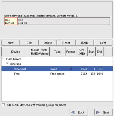
98 98
99 5. Click on NEW to add a new partition. Enter backslash on the Mount Point, as shown. Choose ext3 as your File System Type. Enter size for partition, for example 2000 MB. Choose the Fixed Size radio button. Check "Force to be primary partition". Finally, click on OK. 99

 Choose ext3 as your File System Type.")
100 6. Click on NEW to add a new partition. Enter a Mount Point, for example /data1. (Ensure that you input a backslash before entering the Mount Point.) Choose ext3 as your File System Type. Enter size for partition, for example 100 MB. Choose the Fill to maximum allowable size radio button. Finally, click on OK. 100
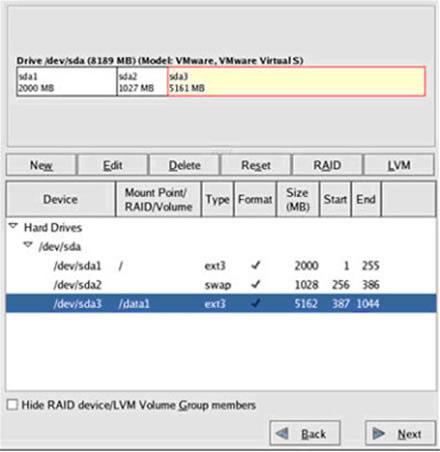
101 101

102 Using Partition Manager How do I format or partition new hard disks once the DVR application has been installed? To format or partition additional hard disks for DVR storage, follow these steps: 1. Double-click the PARTITION MANAGER icon on the Desktop. 2. Enter the root password to open the application window. Please follow the instructions below to avoid damaging the hard disks during partitioning and formatting. 3. On Detection: Hard disk devices are sda, sdb... A display of sda1 and sda2 means there are 2 partitions in hard disk 0. sdb will be hard disk 1. Devices (e.g. sda, sdb) without number suffixes means unpartitioned devices. Detected hard disk devices are seen at the left side of the screen. Select only disk drives with Drive Info - status: available. Do not make any operation on disk drives with the busy status. A busy disk drive means that partition is currently mounted and can not be modified. 102

103 4. On Disk Partition: To make a new partition table follow these steps: a. Select an available disk drive and right-click on it, then select "&Make a new Partition Table". Click Yes on message confirmation. b. At the right side of the screen - list of partitions, right-click the first free entry and select "&Create". c. Set the label and size of the new partition. Set the partition as Primary Partition and an ext3 partition type. Only OS disks need a partition of type swap, so there is no need to create any swap partitions on non-os disks. d. To execute, click the save or commit icon (with diskette image) or click - File Menu &commit then click Yes for confirmation and OK on progress completion. e. If an error appears after committing, format the new partition following the steps outlined in the section below. f. To make a new partition on remaining hard disk space, repeat instructions (b) to (e). 103

104 5. On Formatting a Disk: To format a partition listed at the right side of the screen follow these steps: a. Right-click the partition entry of a selected disk drive and select "&Format". b. Set the label of partition and set an ext3 partition type then click OK. c. To execute/apply, click the save or commit icon (with diskette image) or click - File Menu &commit then click Yes for confirmation and OK on progress completion. d. For another format operation, repeat instructions (a) to (c). 6. To mount a newly formatted partition or hard disk, note the device path of the disk partition (e.g /dev/sdb1) and use the DISK MOUNTER application on the Desktop. 7. Close the application. 104
 editor window will be shown.")
105 Using Disk Mounter How do I mount additional hard disks once the DVR application has been installed? To mount or unmount additional hard disks for DVR storage, follow these steps: 1. Double-click the DISK MOUNTER icon on Desktop. 2. Enter root password. Click YES for backup file message confirmation. The filesystem table (fstab) editor window will be shown. This contains information on all the partitions and storage devices in your computer. Ex. device mountpoint filesystem options dump fsck /dev/sda2 / ext3 defaults 1 1 This means that SDA partition 2 is mounted automatically during boot time at / (root) folder having ext3 filesystem. 105
.")
106 3. To mount a new hard disk, follow these steps: a. Click New button. b. Set the type with disk partition type ext3. DVR uses the ext3 filesystem of Linux. The ext3 file system provides stronger data integrity in the event that an unclean system shutdown occurs. c. Set the device path of additional disk partitions(e.g /dev/sdb1). You can find the device path using the PARTITION MANAGER on the Desktop and select the disk device with drive info - status:available then the partition device path is shown at the right side of the tool window. Please refer to the PARTITION MANAGER usage instructions for details. d. Set the mount point path by selecting an existing directory or creating a new one for the mount point (e.g. /disk2). This just means that your new device or disk is accessible in that specified directory. e. Set the following: *fsck order = last checked. *dump check box = checked. g. Place a comment for that mount point for easier identification of the mounted partition. h. Click Valid and the latest entry will be added at the bottom of the list. i. Select the latest entry added and click Mount button. To check if the mount is successful, click again the Mount button and a message that the disk is mounted already or busy will pop up, click OK then. j. Do steps (a) to (i) to mount another disk partition. k. Click Save button or File Menu Save to mount the newly added partition automatically at boot time. 106
PTZ FUNCTION Presets. 13 Pattern Tracking. 14 Group Run SEARCH & PLAYBACK 17 EMAP. 18 CLIENT SETUP 19 DVR(s). 20 Groups.
. 20 Groups.") 1 REMOTE VIEW 3 Client Login. 5 DVR Connection. 6 Remote Client OSD 7 View Screen 7 Digital Zoom 8 Video Event Log. 8 Image Control. 9 Date & Time 9 Screen Capture.. 10 Forced Recording... 10 Sensors 11
1 REMOTE VIEW 3 Client Login. 5 DVR Connection. 6 Remote Client OSD 7 View Screen 7 Digital Zoom 8 Video Event Log. 8 Image Control. 9 Date & Time 9 Screen Capture.. 10 Forced Recording... 10 Sensors 11
REMOTE CLIENT LX SERIES.
 REMOTE CLIENT LX SERIES Remote View... 4 Client Login... 6 DVR Connection... 7 Remote Client OSD... 8 View Screen... 8 Digital Zoom... 9 Video Event Log... 9 Image Control... 10 Date and Time... 10 Screen
Video Management Software
 Video Management Software User Manual Web: europesecurity.eu Mail: info@europesecurity.eu Tel.: 0541 352 952 User s Manual 2 Contents CHAPTER : XMS CENTRAL USER MANUAL 1 PC REQUIREMENT 3 2 INSTALL 3 3
NetClient software user manual
 NetClient software user manual 1-1. General information Net Client is an application which provides users not only viewing and controling remote DVRs, but also receiving realtime event data or alarm signals
USER MANUAL. Mac Version
 USER MANUAL Mac Version Contents 1 Software Introduction... 1 1.1 Summary... 1 1.2 Install and Uninstall... 1 1.2.1 Install the Software... 1 2 Login Software... 3 2.1 Login... 3 2.2 Control Panel Instruction...
Before Setting. GMS is an integrated security management system that provides a useful solution for central monitoring station operation.
 GMS MANUAL Before Setting What What is is GMS? GMS? GMS is an integrated security management system that provides a useful solution for central monitoring station operation. Minimum Minimum System System
Unisight DVR System. Unisight DVR Manual. Ver rev1.3.4
 Unisight DVR Manual Ver2.7.1027 rev1.3.4 1 Table of Contents System Requirements.8 Unisight DVR Server.. 8 Server Hardware Requirements...8 Server Software Requirements 8 Client Hardware Requirements...
SKY l SYS DVR USER S MANUAL TABLE OF CONTENTS. Skydreamers Systems DVR Page 1
 TABLE OF CONTENTS Main System Application (Control) SERVER Startup Screen 6 Login/Logout/Shutdown 7 Control Screen 7 Setup 7 System Power Management 8 Auto Switching Interval 8 E-map 8 TV-Out 8 On-screen
SAFEGUARD CONTENTS. Digital Video Recorder. Version 1.3. Page. DVR Server S A F E G U A R D
 S A F E G U A R D SAFEGUARD Digital Video Recorder Version 1.3 CONTENTS Chapter 1 Chapter 2 Chapter 3 3.1 3.2 3.3 3.4 3.5 3.6 3.7 3.8 3.9 Chapter 4 4.1 4.2 Remote Client Chapter 5 Chapter 6 Chapter 7 7.1
AVerMedia. AverDiGi EH5116 PRO. Quick Installation Guide
 AVerMedia AverDiGi EH5116 PRO Quick Installation Guide i SPECIFICATIONS ARE SUBJECT TO CHANGE WITHOUT PRIOR NOTICE THE INFORMATION CONTAINED HEREIN IS TO BE CONSIDERED FOR REFERENCE ONLY WARNING TO REDUCE
DVR RANGE ENGINEER MANUAL
 INSPIRE DVR RANGE ENGINEER MANUAL Contents Hardware Inspire DVR range Connections Connecting a mouse Connecting keyboard Connecting PTZ cameras Connecting Keyboard/PTZ Alarm connections Using front panel
Quick User Guide to Linux DVR (V2.0)
") Quick User Guide to Linux DVR (V2.0) 1 Contents Main GUI Setup GUI Preview PTZ Control Manual Recording Schedule Recording Continuous Recording Schedule Recording Motion Detection Recording Playback File-list
Quick User Guide to Linux DVR (V2.0) 1 Contents Main GUI Setup GUI Preview PTZ Control Manual Recording Schedule Recording Continuous Recording Schedule Recording Motion Detection Recording Playback File-list
User Manual. Central Monitoring Software for TER-series recorders. CenPro
 EN User Manual Central Monitoring Software for TER-series recorders CenPro Contents CENPRO USER MANUAL 1 PC REQUIREMENT 3 2 INSTALL 3 3 UNINSTALL 5 4 BASIC OPERATION 7 4.1 Log In 7 4.2 Screen Layout 8
NVMS User Manual. Version 2.1.0
 NVMS-1000 User Manual Version 2.1.0 Contents 1 Software Introduction... 1 1.1 Summary... 1 1.2 Operation Environment... 1 1.3 Install and Uninstall... 2 1.3.1 Install the Software... 2 1.3.2 Uninstall
AVerMedia IWH3216 Touch Quick Installation Guide
 AVerMedia IWH3216 Touch Quick Installation Guide NOTICE SPECIFICATIONS ARE SUBJECT TO CHANGE WITHOUT PRIOR NOTICE. THE INFORMATION CONTAINED HEREIN IS TO BE CONSIDERED FOR REFERENCE ONLY. WARNING TO REDUCE
NVMS User Manual
 NVMS-1000 User Manual Contents 1 Software Introduction...1 1.1 Summary... 1 1.2 Operation Environment... 1 1.3 Install and Uninstall... 2 1.3.1 Install the Software... 2 1.3.2 Uninstall the Software...
eview Network Video Recorder User s Manual
 eview Network Video Recorder User s Manual Version 1.02 2010/02/09 Copyright 2010, All rights reserved. Contents 1. Starting / Closing...1 2. Monitoring...4 2.1. Monitoring Windows Layout...4 2.2. Full
PIVOT CMS CLIENT SOFTWARE USER MANUAL
 PIVOT CMS CLIENT SOFTWARE USER MANUAL 1 CMS USER GUIDE 1.1 PC REQUIREMENT Recommended PC Requirement OS CPU VGA RAM HDD Graphics Card OS CPU VGA RAM HDD Windows Vista, 7 or higher Intel Core2Quad Q9400
User`s Manual. CMS Pro. Professional Central Monitoring Software. Full-featured Enterprise Class Surveillance Solution
 Professional Central Monitoring Software CMS Pro Full-featured Enterprise Class Surveillance Solution User`s Manual This document contains preliminary information and is subject to change without notice.
Unisight Digital Technologies. Unisight DVR Manual Client
 Unisight DVR Manual Client 1 Table of Contents Initial Startup...4 Initial Startup...4 Channel Grid...6 DVR Information Window...6 Grid Layout Buttons...7 Camera Status LEDs...7 Extra Function Buttons...7
Chapter 1 Features FEATURES
 Chapter 1 Features Operation Playback, recording and network transmission simultaneously Real time full screen or quad screen display 2X digital zoom and Picture-in-picture display Easy operations by shuttle
Digital Recorder End User Guide. Official UK distribution partner
 Digital Recorder End User Guide Official UK distribution partner 2 Installer Information Contents General Operation Mouse Operation Logging into the System Quick Menu PTZ Control 4 5 5 6 Playback Operation
NVMS User Manual
 NVMS-1000 User Manual Contents 1 Software Introduction...1 1.1 Summary... 1 1.2 Operation Environment... 1 1.3 Install and Uninstall... 2 1.3.1 Install the Software... 2 1.3.2 Uninstall the Software...
JVS-D7216 Standalone DVR User Manual
 Menu JVS-D7216 Standalone DVR User Manual JVS-D7216 Standalone DVR Instructions 1. Introduction..4 1.1 Product Description...4 1.2 Features..4 1.3 Specifications...4 2. Product Features....6 2.1 Panel
QSD2308L/QSD2316L DVR User s Manual
 QSD2308L/QSD2316L DVR User s Manual NOTE: We use two different front panel designs on these models. They have the same function buttons but they are arranged differently. Please match the front panel on
Lite H.264 DVR Setup Guide
 Package Content Lite H.264 DVR Setup Guide Inspect the packaging carton. Make sure the Lite H.264 DVR is properly delivered. Remove all items from the box and make sure the box contains the following items.
TruVision DVR 60 Quick Start Guide
 Content Package contents 1 Installation environment 1 Setting up the TVR 60 1 Connecting the devices 2 Turning on and off the TVR 60 2 Operating the TVR 60 3 DDNS settings 5 Live mode 5 Quick Archive 5
Contents Contents. Chapter 1. Program Installation. Chapter 2. For the start of CMS. Chapter 3. Monitoring. Chapter 4. E-Map Mode
 CMS User's Manual Contents 0 Contents Chapter 1. Program Installation 1.1 PC specifications 1.2 Program Installation Chapter 2. For the start of CMS 2.1 Site Registration Setup (Network Camera Registration)
Digital Recorder End User Guide
 Digital Recorder End User Guide metcalfeallen www.metcalfeallen.co.uk - 01884 38222 - admin@metcalfeallen.co.uk Installer Information Metcalfe Allen Ltd Unit 7 Saunders Way Kingsmill Industrial Estate
960H H.264 DVR Setup Guide
 Package Content 960H H.264 DVR Setup Guide Inspect the packaging carton. Make sure the 960H H.264 DVR is properly delivered. Remove all items from the box and make sure the box contains the following items.
Lorex Client 7.0 & Lorex Message Master
 Lorex Client 7.0 & Lorex Message Master Software Manual English Version 1.0 MODELS: L19WD Series www.lorexcctv.com Includes L19WD800 & L19WD1600 Copyright 2008 Lorex Technology Inc. Table of Contents Table
Quick Start Guide 4/8/16-CH DVR.
 Quick Start Guide 4/8/16-CH DVR 1. Install Hard Drive &DVD Writer 1.1 Install Hard Drive Notice: 1. Support two SATA hard drives. Please use the hard drive the manufacturers recommend specially for security
icms Pro USER S Manual Ver 1.4
 icms Pro USER S Manual Ver 1.4 Contents Panes... 7 How Can User Rights Affect Your Use of icms Pro SW?... 10 Minimum System Requirements... 11 Installing the icms Pro SW... 12 Download icms Pro from icatchinc
NVMS1000. User Manual
 NVMS1000 User Manual Contents 1 Software Introduction... 1 1.1 Summary... 1 1.2 Operation Environment... 1 1.3 Install and Uninstall... 2 1.3.1 Install the Software... 2 1.3.2 Uninstall the Software...
Avigilon Control Center Web Client User Guide
 Avigilon Control Center Web Client User Guide Version: 4.12 Standard PDF-WEBCLIENT-S-E-Rev2 Copyright 2013 Avigilon. All rights reserved. The information presented is subject to change without notice.
NUBIX H.264 DVR Setup Guide
 Package Content NUBIX H.264 DVR Setup Guide Inspect the packaging carton. Make sure the NUBIX H.264 DVR is properly delivered. Remove all items from the box and make sure the box contains the following
Chapter 3 Operating instructions
 Chapter 3 Operating instructions Summary This chapter describes the how to control and navigate through the TVR 30 s menus and options. Content Control interfaces 10 Controlling the TVR 30 10 Front panel
EH6000H series EH6108H + /EH6216H + Quick User Guide
 EH6000H series EH6108H + /EH6216H + Quick User Guide COPYRIGHT COPYRIGHT 2011 AVer Information Inc. All rights reserved. No part of this document may be reproduced or transmitted in any form, or by any
RAS (Remote Administration System)
") RAS (Remote Administration System) Digital Video Recorder Software User Guide Document 900.0314 Rev 2.00 RAS User Guide Revisions Issue Date Revisions 1.00 08/04 New document. 1.01 04/05 Update template,
RAS (Remote Administration System) Digital Video Recorder Software User Guide Document 900.0314 Rev 2.00 RAS User Guide Revisions Issue Date Revisions 1.00 08/04 New document. 1.01 04/05 Update template,
PROFESSIONAL PROTECTION INCORPORATED
 PROFESSIONAL PROTECTION INCORPORATED EAGLE EYE DIGITAL VIDEO RECORDING AND SURVEILLANCE SYSTEMS 1101 Tyvola Road Suite 202 Charlotte North Carolina 28217-3515 Business: (704) 523-1660 Facsimile: (704)
User s Manual of DVR ULTIMAX. Remote Client Software V wersja 2.40
 User s Manual of DVR ULTIMAX Remote Client Software V 4.0.1 ULTIMAX-304 ULTIMAX-308 ULTIMAX-316 ULTIMAX-504 ULTIMAX-508 ULTIMAX-516 ULTIMAX-704 ULTIMAX-708 ULTIMAX-716 wersja 2.40 Index 1 Software Install,
DVR SYSTEM User s Manual
 DVR SYSTEM User s Manual Manual Revision : Version 5.3 above Release Date : July 1. 2004 INDEX Chapter. Main Screen -1. Explanation of Main Screen A ~ N Functions per button -2. Pan/Tilt Control O Pan/Tilt
SmartWatch Eco/Eco Compact
 SmartWatch Eco/Eco Compact Digital Video Recorders SmartWatch Eco SmartWatch Eco Compact Quick User Guide Index Box Contents...3 Front Panel Controls...4-5 SmartWatch Eco Compact...4 SmartWatch Eco...5
Vegas Valley Video Systems. Vegas Valley DVR Manual TZHC Series Server
 Vegas Valley DVR Manual TZHC Series Server 1 Table of Contents Initial Startup...4 Initial Setup...4 Live Preview Mode...5 DVR Information Window...6 Camera Status LEDs...6 Channel Grid...7 Grid Layout
DiViS Net (Integration)
") DiViS Net (Integration) Installation and User s Guide Ver 12.12.0 Digital Video Security System Digital Video Recorder www.divisdvr.com DiViS DVR.com *All contents of this document may change without prior
DiViS Net (Integration) Installation and User s Guide Ver 12.12.0 Digital Video Security System Digital Video Recorder www.divisdvr.com DiViS DVR.com *All contents of this document may change without prior
Analog High Definition DVR. Stand alone digital video recorder. User Manual H.264 AHD DVR
 Analog High Definition DVR Stand alone digital video recorder User Manual H.264 AHD DVR WARNING To reduce the risk of fire or electric shock, do not expose this appliance to rain or moisture. All the safety
Table of Contents Surveillance Center Overview...3 Log...30 Live Camera Panel...31 Live Camera Panel Explained I...32
 Surveillance Center Overview...3 Introduction...3 System Requirements... 4 Features... 5 Checking the Hardware Requirements... 6 Installing and Accessing the Module... 8 Connecting a Camera to the Network...
Central Management Software. Cam Viewer 3 Lite. User Manual
 Central Management Software Cam Viewer 3 Lite User Manual Version 1.0.0 Table of Contents 1. System Requirement...4 2. Software Installation...5 3. Configuration Wizard...9 3.1 Channel...10 3.1.1 Adding
VMS-A1 Client Software. User Manual
 VMS-A1 Client Software User Manual Contents Contents... 2 Chapter1. Overview... 4 1.1 Description... 4 1.2 Features & Functions... 4 Chapter2. Update Info... 6 Chapter3. Starting VMS-A1... 7 3.1 Installing
HLong Asia Industrial
 SDI DVR Stand alone digital video recorder HLong Asia Industrial Thank you for using the company's products! This manual describes only the host functions basic operation. Product design and specification
Table of Contents. Tops Digital Solutions DVS 2000 Series Users Manual Ver.2.0 2
 DVS 2000 Series Table of Contents Ch. 1. Preface 4 How to Use This Guide... 4 Conventions 4 Related Documents... 4 Support.. 5 Safety Warnings and Information.. 5 Ch. 2. Overview. 6 Overview 6 Features..
YesCam View User Manual For Easy Connection YesCam Series
 YesCam View User Manual For Easy Connection YesCam Series Seeing the video from anywhere Version:1.2.4 Date:2015.02.3 1 Table of Content 1. Introduction...4 2. System Requirement...4 3. Install YesCam
Network Video Recorder Quick Operation Guide
 Network Video Recorder Quick Operation Guide UD.6L0202B1351A01 TABLE OF CONTENTS NVR Pre-Installation... 2 NVR Installation... 2 Hard Disk Installation... 2 Front Panels... 6 DS-9500NI-ST/RT Front Panel...
Multi-NVR Manager. Quick Start Configuration Usage
 Multi-NVR Manager Quick Start Configuration Usage 2014. All rights are reserved. No portion of this document may be reproduced without permission. All trademarks and brand names mentioned in this publication
DVR User s Manual. For H FPS /8-channel digital video recorder All rights reserved. Rev
 QSDT8DP DVR User s Manual For H.264-240 FPS /8-channel digital video recorder All rights reserved Rev 120209 i QSDT8DP User s Manual CAUTION Please read this user manual carefully to ensure that you can
Blue v2 INSPIRE DVR RANGE USER MANUAL
 INSPIRE Blue v2 DVR RANGE USER MANUAL Contents Logging into the DVR Mouse menu Live viewing Playback Smartphone viewing setup Smartphone viewing Copy to USB/Disc Using Cop player 2 playback software Using
SPECIFICATIONS ARE SUBJECT TO CHANGE WITHOUT PRIOR NOTICE. THE INFORMATION CONTAINED HEREIN IS TO BE CONSIDERED FOR REFERENCE ONLY.
 COPYRIGHT 2010 by AVerMedia Information, Inc. All right reserved. Reproduction without permission is prohibited. No part of this document may be reproduced or transmitted in any form, or by any means without
DiViS Net (Integration)
") DiViS Net (Integration) Installation and User s Guide Ver 12.00.1 Digital Video Security System Digital Video Recorder www.divisdvr.com Chance-i USA Corp. *All contents of this document may change without
DiViS Net (Integration) Installation and User s Guide Ver 12.00.1 Digital Video Security System Digital Video Recorder www.divisdvr.com Chance-i USA Corp. *All contents of this document may change without
Appendix A. esync DVR Manual Appendix A. FCC Compliance Statement WARNING. Revision A esync Manual esync
 Appendix A Appendix A FCC Compliance Statement Model Name: esync Series (SSA-1648e, SSA-0824e, SSA-0424e). This device complies with Part 15 of the FCC Rules. Operation is Subject to the following two
NVMS1000. User Manual
 NVMS1000 User Manual Contents 1 Software Introduction... 1 1.1 Summary... 1 1.2 Operation Environment... 1 1.3 Install and Uninstall... 2 1.3.1 Install the Software... 2 1.3.2 Uninstall the Software...
Central Management Software for NVR-915 / NVR-1615 CV5-M256
 Central Management Software for NVR-915 / NVR-1615 Table of Contents Chapter 1. Main Console... 4 1.1 Tool Bar... 4 1.2 NVR List... 5 1.3 Division List... 7 1.4 Group List... 9 1.5 PTZ Panel...11 1.6 Operation
H.264 4/8/10/16-Channel High-Definition DVR Quick Start Guide
 H.264 4/8/10/16-Channel High-Definition DVR Quick Start Guide Products: BLK-HD4D, BLK-HD4E, BLK-HD8D, BLK-HD10D, BLK-HD16D BLK-HD4E (upper) BLK-HD4D and BLK-HD8D (middle) BLK-HD10D and BLK-HD16D (lower)
VIPER. Quick User Guide
 VIPER Quick User Guide 1 2 Please read this manual thoroughly before use and keep it handy for future reference. Contents 1. Overview... 1 1.1 DVR Description... 1 1.2 DVR power up... 1 1.2.1 Login...
LOREX CLIENT 3.0 SOFTWARE MANUAL IRMS Integrated Remote Management Software
 LOREX CLIENT 3.0 SOFTWARE MANUAL IRMS Integrated Remote Management Software Instruction Manual English Version 2.0 Copyright 2007 Lorex Technology Inc. www.lorexcctv.com Table of Contents Overview... -
Quick Start Guide. Menu Structure. Startup and Shutdown. Using the Setup Wizard. DS-8100-S Series DVR (V2.0.1)
") Quick Start Guide DS-8100-S Series DVR (V2.0.1) Menu Structure The menu structure of the DS-8100-S Series DVR is as followed: 1. Enter the Shutdown menu by clicking on Menu > Shut down. 2. Select the Shutdown
Quick Start Guide DS-8100-S Series DVR (V2.0.1) Menu Structure The menu structure of the DS-8100-S Series DVR is as followed: 1. Enter the Shutdown menu by clicking on Menu > Shut down. 2. Select the Shutdown
R4, R8, R16 Digital Video Recorders Quick Setup Guide
 R4, R8, R16 Digital Video Recorders Quick Setup Guide This guide provides instructions to initially setup the R16 (16 channel) digital video recorders (DVR). The DVR supports these advanced features: 2
Quick Start Guide 4/8/16-Ch DVR
 Quick Start Guide 4/8/16-Ch DVR 1 1. Install Hard Drive &DVD Writer 1.1Install Hard Drive Notice: 1. Support two SATA hard drives. Please use the hard drive the manufacturers recommend specially for security
TruVision DVR 30 Quick Start Guide
 TruVision DVR 30 Quick Start Guide Content Contact information 1 Package contents 1 Installation environment 1 Setting up the TVR 30 1 Connecting the devices 2 Turning on the TVR 30 2 Operating the TVR
H.264 Network DVR. Quick Start
 341Z H.264 Network DVR Quick Start GUI Display with USB Mouse Control Please read instructions thoroughly before operation and retain it for future reference. For the actual display & operation, please
icms Pro USER s MANUAL Ver 1.0
 icms Pro USER s MANUAL Ver 1.0 Contents Target Audience for this Document... 5 Copyright, Trademarks and Important Information... 5 Copyright... 5 Disclaimer... 5 Introduction... 6 Tabs... 6 Panes... 7
The ULTIMA series DVR can be operated with a mouse or remote controller under the four main modes listed below:
 HD-SDI User Manual 13433 NE 20 th ST # T, Bellevue, WA 98005 Tel : 425-457-7790 Toll Free : 1-866-966-6766 Fax : 425-457-7791 Web : http://www.moosoo.com email : moosoo@moosoo.com CH3. How to Use 3-1.
Ver HDxViewer. Manual
 Ver. 13.09.06 HDxViewer Manual Symbols and Letters used in this Manual Importance mark : Arrangement of items to be considered for completing work Additional information or tip to avoid in order to completing
SDI Digital Video Recorder. Quick Operation Guide
 SDI Digital Video Recorder Quick Operation Guide Thank you for purchasing our product. If there is any question or request, please do not hesitate to contact dealer. This manual is applicable to HDDVRXXXX-SDI
Quick Start Guide 4/8/16/24-Ch DVR
 Quick Start Guide 4/8/16/24-Ch DVR 1.1 Install Hard Drive 4/8/16/24-CH DVR Quick Start Guide Notice: 1.4/3/16-ch DVR supports one SATA hard drive. 24-ch DVR supports three SATA hard drives. Please use
W Box VMS BOX T E C H N O L O G I E S.
 W Box VMS BOX T E C H N O L O G I E S www.wboxtech.eu Contents Contents... 1 Overview... 3 1.1 Description... 3 1.2 Running Environment... 3 1.3 Function Modules... 3 Live view... 6 2.1 User Registration
IWH3216 Touch/Touch II
 IWH3216 Touch/Touch II 16CH Embedded Hybrid DVR Quick User Guide COPYRIGHT 2012 AVer Information Inc. All rights reserved. No part of this document may be reproduced or transmitted in any form, or by any
CMS User's Manual. Version 1.9
 CMS User's Manual Version 1.9 Introduction 0 Introduction [ Principal function ] This CMS Interlocked with megapixel camera. This CMS supports easy connection and registration of the site(camera) This
Quick Start Guide. Plug n Play NVR DS-7604NI-SE/P DS-7608NI-SE/8P.
 Quick Start Guide Plug n Play NVR DS-7604NI-SE/P DS-7608NI-SE/8P Note: For more information refer to the complete User Manual located on the CD-ROM OVERVIEW 1. Overview 2. Main Menu Layout 3. Formatting
Unisight DVR System. Unisight DVR Manual. Version Rev 1.0
 Unisight DVR Manual Version 1.8.0131 Rev 1.0 1 Table of Contents System Requirements...5 Server Hardware Requirements...5 Server Software Requirements...5 Client Hardware Requirements...5 Client Software
Table of Contents. Chapter 1 Introduction Features System Diagram... 2 Multi-Server... 2 Single-Server... 3
 inex Standard Table of Contents Chapter 1 Introduction... 1 1.1 Features... 1 1.2 System Diagram... 2 Multi-Server... 2 Single-Server... 3 Chapter 2 Installation... 5 2.1 Product Information... 5 Package
Pro71600N3 NVR User Manual
 Pro71600N3 NVR User Manual User Information Admin User Name: Admin Password: IP Address: System Name: Table Of Contents 1. Menu Operation...4 1.1 Main Menu...4 2. Start & Shutdown System...5 2.1 Start
Digital Video Recorder User Manual. DVR User Manual. For H channe/ 8-channel/16-channel Digital Video Recorder All rights reserved
 DVR User Manual For H.264-4-channe/ 8-channel/16-channel Digital Video Recorder All rights reserved i CAUTION Please read this user manual carefully to ensure that you can use the device correctly and
CCTV42 System2 DVR Quick Start Guide 4/8/16-Ch DVR
 CCTV42 System2 DVR Quick Start Guide 4/8/16-Ch DVR If you have purchased a DVR / Hard drive package from us then we will have already installed the hard drive(s) and configured the basic settings on your
QSTD2404/QSTD2408/QSTD2416 Digital Video Recorders User s Manual
 QSTD2400 Series DVR User s Manual QSTD2404/QSTD2408/QSTD2416 Digital Video Recorders User s Manual For H.264-4-channel/ 8-channel/16-channel Digital Video Recorders All rights reserved Rev 091708 i QSTD2400
Quick Start Guide 4/8-CH DVR
 Quick Start Guide 4/8-CH DVR 1 1. Install Hard Drive &DVD Writer 1.1 Install Hard Drive Notice: 1. this series support one SATA hard drives. Please use the hard drive the manufacturers recommend specially
RemoteManager Software
 RMS RemoteManager Software User Manual Contents of this user manual are protected under copyrights and computer program laws. Functions or configurations are subject to be changed or modified without prior
USER GUIDE STAND-ALONE. 4 channel MPEG-4 Triplex DVR V Stand-Alone DVR User Guide
 USER GUIDE STAND-ALONE 4 channel MPEG-4 Triplex DVR V. 1.4 This document contains preliminary information and subject to change without notice. SAFETY PRECAUTIONS EXPLANATION OF SYMBOLS This symbol is
VIP Kit 16 channel software manual. Set up and user manual for Vista s VIP Kit software IP CCTV system
 VIP Kit 16 channel software manual Set up and user manual for Vista s VIP Kit software IP CCTV system Table of Contents 1. Introduction of Program... 1 2. Preparations before operating... 1 2.1 Minimum
SecuGuard. Basic 5.0. User s manual. Dec Version: 5.0.x
 SecuGuard Basic 5.0 User s manual Dec. 2009 Version: 5.0.x SecuGuard Basic System Requirement...5 Installation...6 Before Installing the Software... 6 Starting the Installation... 6 Quick Start...9 Install
Exxi Net (Integration)
") Exxi Net (Integration) Installation and User s Guide Ver 11.06.x Digital Video Security System Digital Video Recorder www.exxicom.com *All contents of this document may change without prior notice. INDEX
Exxi Net (Integration) Installation and User s Guide Ver 11.06.x Digital Video Security System Digital Video Recorder www.exxicom.com *All contents of this document may change without prior notice. INDEX
Table of Contents. Chapter 1 Overview In This Manual ATVision Pro Features Product Information... 1
 Remote Management Software (ATVision Pro) Table of Contents Chapter 1 Overview... 1 1.1 In This Manual... 1 1.2 ATVision Pro Features... 1 1.3 Product Information... 1 Chapter 2 Installation... 3 Chapter
TruVision Recorder Operator Guide
 TruVision Recorder Operator Guide Live view In the viewer you can see displayed on the live image the current date and time, camera name, and whether a recording is in progress. Information on the system
Pro7804N1 NVR User Manual
 Pro7804N1 NVR User Manual Pro7804N1 User Manual BW R6.indd 1 User Information Admin User Name: Admin Password: IP Address: System Name: Table Of Contents 1. Menu Operation...4 1.1 Main Menu...4 2. Start
HD SDI DVR & Analog (960H) DVR User s Guide (Ver. 3.2)
 DVR User s Guide (Ver. 3.2)") HD SDI DVR & Analog (960H) DVR User s Guide (Ver. 3.2) HD-SDI DVR Models: HDH4, HDH8, HDH16, HDR4, HDR8, HDR16 Analog (960H) DVR Models: HR4, HR8, HR16 About This User s Guide Before operating the unit,
HD SDI DVR & Analog (960H) DVR User s Guide (Ver. 3.2) HD-SDI DVR Models: HDH4, HDH8, HDH16, HDR4, HDR8, HDR16 Analog (960H) DVR Models: HR4, HR8, HR16 About This User s Guide Before operating the unit,
ART. IPSWI000A USER S MANUAL
 ART. IPSWI000A USER S MANUAL Via Don Arrigoni, 5 24020 Rovetta S. Lorenzo (Bergamo) http://www.comelitgroup.com e-mail: export.department@comelit.it inex Basic Table of Contents Chapter 1 Introduction...1
Table of Contents. Index
 Index Table of Contents Chapter 1 Notice for All Users...1-1 Chapter 2 Installation...2-1 2-1 HD NVR Manager Setup...2-1 2-1-1 Installation Steps...2-2 2-1-2 License Activation...2-9 Chapter 3 SCM Program...3-1
Digital Video Recorder User Manual. DVR User Manual. For H channel/ 8-channel/16-channel Digital Video Recorder All rights reserved
 DVR User Manual For H.264-4-channel/ 8-channel/16-channel Digital Video Recorder All rights reserved i CAUTION ii Please read this user manual carefully to ensure that you can use the device correctly
The Intelligent Surveillance Solution. User manual
 The Intelligent Surveillance Solution User manual CONTENTS 1.1 System Requirement... 1 1.2 Installation... 1 1.3 Quick Start... 5 2.1 Start Menu... 10 2.2 Information Window:... 12 2.3 PTZ Config:... 12
MPEG4 4 Channel Digital Recording System VXM4-4. User Manual
 MPEG4 4 Channel Digital Recording System VXM4-4 User Manual CONTENTS Before installing 1 Key features 2 Front panel description 3 Rear panel description 4 Getting started 5 Connect and switch on 5 Configuring
Hybrid DVR Quick Start Guide
 Hybrid DVR Quick Start Guide Thank you for purchasing our product. If there is any question or request, please do not hesitate to contact dealer. This manual is applicable to most Hybrid DVR models. DVR