Various Emerging Time- Triggered Protocols for Driveby-Wire
|
|
|
- Donald Welch
- 5 years ago
- Views:
Transcription
1 Various Emerging Time- Triggered for Driveby-Wire Applications Syed Masud Mahmud, Ph.D. Electrical and Computer Engg. Dept. Wayne State University Detroit MI January 11, th Annual Winter Workshop U.S. Army Tank-Automotive RD&E Center, Warren, MI
2 Speaker s Background Received Ph.D. in Electrical Engineering from the University of Washington, Seattle (1984). Worked for Oakland University, Rochester, Michigan, during Has been working for Wayne State University since Published over 90 technical papers in referred journals and conference proceedings. 2
3 Speaker s Current Areas of Interest Intelligent Vehicles, Intelligent Transportation Systems, In-Vehicle Networking, Time Triggered for Real-Time Applications, Collision Warning and Collision Avoidance systems, Security in Wireless Communications, and Embedded Systems. 3
4 Outline of the Talk Event-Triggered versus Time-Triggered Operations. Need for Time-Triggered. Time-Triggered Protocol (TTP). A Quick Overview of the CAN Protocol. Time-Triggered CAN (TTCAN) Protocol. The FlexRay Protocol. Comparison of TTP, TTCAN and FlexRay. 4
5 Event-Triggered Operations TIME Brake Message Steering- Wheel Message Brake Message Steering- Wheel Message Brake Event Steering Wheel Event Brake Event Steering Wheel Event 5
6 Problems with Event-Triggered Communications Message latency is not deterministic. Though the maximum latency could be quantified, the latency jitter can t be eliminated. Lower bus utilization to avoid high latencies. Babbling idiot problems due to faulty nodes. A higher priority faulty node can monopolize the bus. 6
7 Time-Triggered Operations TIME Brake Message Steering- Wheel Message Vehicle Speed Brake Message Steering- Wheel Message Vehicle Speed 7
8 Benefits of Time-Triggered Communications Deterministic latency. No latency jitter. Very high bus utilization. High system throughput due to high bus utilization. A faulty node can t monopolize the bus. Thus, there is no Babbling Idiot problem. 8
9 Need for Time Triggered 9
10 Hard Real-Time Distributed Control System Hard real-time systems such as x-bywire systems need deterministic latencies. In an event-triggered communication, though the safety-critical messages can be prioritized to keep the latencies under a bound, the latency jitters of these messages can t be eliminated. 10
11 Latency Jitter 11
12 Effect of Latency Jitters on Hard Real- Time Distributed Control System Control applications do not run well under latency jitters. Latency jitters produce overshoots in the output of a control application. If the latency jitter is too high, then the control system may even become unstable. Thus, Time-Triggered protocols are appropriate for hard real-time systems. 12
13 Time-Triggered Protocol (TTP) 13
14 A TTP/C Cluster CNI: Communication Network Interface 14
15 TTP/C Network Topology 15
16 TTP/C Network Topology (contd.) 16
17 TTP/C Network Topology (contd.) 17

18 Overview of an Electronic Module MEDL: Message Descriptor List 18
19 Structure of the Message Descriptor List (MEDL) Each TTP node includes a globally known MEDL that controls the cluster s scheduling policy. (A detailed description of the MEDL is given later.) 19
20 Frame-Application Data-Message 20
21 Media Access Scheme 21

22 Multiplexed Slot Assignment 22
23 Slot Timing A TDMA slot begin with the start of the Transmission Phase (TP). The time at which TP begins is called the Action Time (AT). The evaluation of received data and execution of protocol services are done at Post Receive Phase (PRP). 23
24 Slot Timing The Pre-Send Phase (PSP) is necessary to load the schedule information of the next slot from the MEDL and to prepare the transmission/reception of data at the next AT. Thus, the start of PSP is the start of node slot. The Idle Phase is used as tolerance if extra time is need for PRP. 24
25 Slot Timing A node performs all house keeping operations during the Inter-Frame Gap (IFG). During IFG there is no traffic on the bus. 25
26 Controller State (C-state) It describes the internal state of a TTP/C controller. Although the C-state is calculated locally by each controller, it represents a global view of the cluster and must agree with the calculated C-states of the other nodes. A C-state disagreement between a node and the majority of the other nodes will mark this node as faulty. 26
27 Controller State (C-state) The C-state consists of the following items: Global Time The global time of the transmission of the current node slot at the start of PSP. Round Slot Position The current slot in the cluster cycle updated at the start of the node slot (begin of PSP). Cluster Mode The current active cluster mode the controller is operating in, updated at the start of the node slot. (Examples of cluster modes for an aircraft are on ground, take off, cruising and landing.) 27
28 Controller State (C-state) Deferred Pending Mode Changes (DMC) If a mode change is requested for the start of the next cluster cycle, the pending request is saved in the C-state, updated at the end of the PRP after the request is received. Membership Information Consistent view of the activity of all nodes in the cluster. A node is in the membership after having correctly sent in its last slot. A node is outside the membership, if having not sent or sent incorrectly. 28
29 Frame Types and Formats A frame consists of the following parts: Application data prepared by the host. Explicit C-state for agreement check between the nodes. Mode change requests. 29
30 Frame Types and Formats Additional frame description data, e.g. a frame type identifier. CRC calculated over the frame for detection of errors. 30
31 Frame Types and Formats Implicit C-state calculated into the frame CRC, if no explicit C-state is transmitted Unique cluster schedule ID to guarantee that only nodes with the same schedule can communicate with each other. 31
32 Cold Start Frame This frame is used for the cluster startup and must contain the following information: Global time of sending (C-state time) Round slot position of the sender (must be located in the first TDMA round in the first cluster mode) 32
33 Cold Start Frame Frame type identifier, which indicates this frame as cold start frame CRC calculated over the frame. 33
34 Cold Start Frame Unique cluster schedule ID is also calculated into the frame s CRC Other nodes may integrate on this frame by taking over the C-state time and the schedule position. The sender is identified by the round slot position and is set into the membership. 34
35 Explicit versus Implicit C-state Implicit C-states improves performance, because no bandwidth on the channel is spent for the C-state transmission. The saved bandwidth can be used to send more application data. On the other hand the logic for comparing the local C-state with the received implicit one is more complex at the receiver and may take a longer processing time. Explicit C-states are required for the integration process and cluster startup. 35
36 Startup of a Node The startup of each node consists of three steps: Initialization of the host and the TTP/C controller. Listening on the channels for frames with explicit C-state for the duration of the listen timeout. If such a frame is received, the controller starts the integration to adopt the C-state. 36
37 Startup of a Node The startup of each node consists of three steps: If no running cluster is detected, it checks the conditions for performing a cold start: the host has updated its life-sign the Cold Start Allowed flag (CF) is set in the MEDL the maximum number of allowed cold starts for this node is not reached If these conditions are fulfilled, the node sends a cold start frame, increases the cold start counter and processes the TDMA scheme. 37
38 Integration Integration is the process of a node to synchronize with a running cluster. The node listens on the channels to receive a frame with explicit C-state or a cold start frame and then integrates on it. The cluster schedule must provide at least a minimum of one frame per channel with explicit C-state every two TDMA rounds (minimum listen timeout). 38
39 Integration 39 Observed Channel: Channel on which traffic is detected first.
40 Big Bang A mechanism that ensures that in case of a startup collision between two cold start nodes no node will integrate on any of the collided frames. If Propagation Delay > Cold Start Frame Duration different nodes may integrate on different cold starters. To prevent this problem the first received cold start frame is rejected by all nodes and the listen timeout is restarted. 40
41 Big Bang (contd.) The cold start nodes will not detect any traffic during their TDMA round and start their startup timeouts after they get a Communication Blackout 1 error. Because the difference between any startup timeouts is at least a slot duration and therefore longer than the maximum propagation delay, no further inconsistent collision will appear. 1 Communication Blackout: Error raised by the controller if no traffic was observed on any channel during one TDMA round 41
42 Startup 42
43 Startup Collision Scenario Without Big Bang 43

44 Startup Collision Scenario Using Big Bang 44
45 Host/Controller Life-Sign The host must provide the controller with a life-sign before each sending slot of the node. If the life-sign is not updated by the host, the controller does not send but remains synchronized with the cluster. An updated host life-sign is also a precondition for a controller to startup a cluster by sending a cold start frame. 45
46 Membership The membership service informs all nodes of a cluster about the operational state of each node within a latency of about one TDMA round. A node is operational at time now If the host computer of the node has updated its life-sign within the last TDMA round and the communication controller is operating and synchronized with the rest of the cluster. 46
47 Membership Vector The membership status of each member node is recorded in the membership vector. The membership vector is an array of flags with a length to equal to the number of member nodes in the cluster. The membership flag of a node indicates whether or not the node is alive. Membership Flag Nodes MEMB(A) A MEMB(B) B MEMB(C) C Membership Vector
48 Acknowledgment Scheme The TTP/C acknowledgment service is based on the membership service. Acknowledgment of the receipt of a frame by the successor of the sender is performed implicitly through the node membership in the C-state. During a sending slot a node sends two frames. If any of these two frames is received correctly by a receiver, the receiver considers the sender to be active. 48
49 Acknowledgment Scheme If the successor of node A, say node B, has received a correct frame from A, MEMB(A) is TRUE in B s transmission. Thus A can use B s frame for acknowledgment. During normal operation, A performs two CRC checks over B s frame. Check Ia: A sets MEMB(A) to TRUE and MEMB(B) to TRUE. It then performs the CRC check over the received frame, concatenated with its local C-state. Check Ib: A sets MEMB(A) to FALSE and MEMB(B) to TRUE. Then it performs the CRC check over the received frame, concatenated with its local C-state. 49
50 Acknowledgment Scheme If the CRC check Ia is OK, node A assumes that the transmission was correct and remains in the membership. If the CRC check Ia is not OK, then at least one failure has occurred. If both checks (check Ia and check Ib) fail, it is assumed that a transient disturbance has corrupted B s frames or B is not operational at all. 50
51 Acknowledgment Scheme If check Ia to fail and check Ib to pass, then it is not certain whether A or B is correct. A final decision of the cause is made after receiving the next frame from A s second successor, say node C. 51
52 Acknowledgment Scheme 52
53 Acknowledgment Scheme In the next slot, A performs two CRC checks over the frames received from C. Check IIa: A sets MEMB(A) to TRUE and MEMB(B) to FALSE. It then performs the CRC check over the received frame from C. Check IIb: A sets MEMB(A) to FALSE and MEMB(B) to TRUE. It then performs the CRC check over the received frame from C. 53
54 Acknowledgment Scheme 54
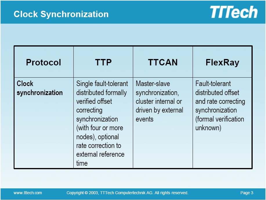
55 Message Descriptor List (MEDL) Each controller has an MEDL whose layout looks like the one shown below. 55
56 Schedule Parameters Cold Start Allowed Flag (CF) If this flag is set the node can enter the cold start state. Cold Start Integration Allowed Flag (CIA) The controller may only integrate on a cold start frame if this flag is set. Otherwise the controller must wait for a regular frame with explicit C-state to integrate. 56
57 Schedule Parameters (contd.) Minimum Integration Count (MIC) A controller needs a frame with explicit C-state from another node to integrate into a cluster. To ensure that controllers do not integrate on faulty frames and re-transmit the faulty C- state in their own subsequent transmissions, a specific number of correct frames (only the first one has to have an explicit C-state) has to be received before a node can transmit actively. 57
58 Schedule Parameters (contd.) Maximum Cold Start Entry This field specifies the maximum number of cold start attempts by the controller. Maximum Acknowledgment Failure Count (MAFC) This field specifies the number of successive acknowledgment failures at which the controller freezes. 58
59 Schedule Parameters (contd.) Communication Bit Rates Used to define the bit rates on the two channels of the cluster. Startup Timeout Startup timeout for the node. Listen Timeout Listen timeout for the node. Flag Position in Membership Vector Own flag position in the membership vector. 59
60 Identification Section Cluster Schedule Identification This field contains an identifier of the cluster design. The cluster designer (tool) has to ensure that the schedule IDs differ for different designs. Only nodes based on the same cluster design can participate in the same cluster. Application Identification Unique ID used by the host application to verify the actual MEDL is compatible to it. 60
61 Round Slot Selection Sending Slot Flag (SS) Marks that the node is allowed to send in this slot. CNI Addresses of Frames Defines the address of the application data transmitted in the slot. Slot Duration The slot duration entry contains the duration of the current node slot in units of macroticks. 61
62 Round Slot Selection Frame Types Marks the type of the frames transmitted in the round slot (e.g. with implicit or explicit C-state). Application Data Length of Frames Defines the length of the application data in the frames. Clock Synchronization (ClkSyn) Flag If this flag is set, the clock synchronization algorithm is executed in this slot. 62
63 Round Slot Selection (contd.) Synchronization Frame (SYF) Flag If the synchronization frame flag is set, the frames arriving in the slot are used by the clock synchronization algorithm: For these frames the deviation between the expected and the actual arrival time of the frame is measured and put onto the clock synchronization stack. Mode Change Permissions (MCP) Permission for a mode change request to a specified cluster mode. Flag Position in Membership Vector This entry contains the flag position of the sender in the membership vector. 63
64 Protocol States Freeze (0) The execution of the protocol is halted until the controller is turned on by setting the Controller On (CO) flag. Init (1) The controller enters the init state after it is switched on (CO flag is set by the host). Listen (2) The controller enters the listen state when the initialization has been completed and tries to integrate on a received frame. Cold Start (3) The controller enters the cold start state if it is allowed to (CF flag set and host alive). 64
65 Protocol States (contd.) Active (4) The controller transmits frames. Passive (5) The controller is synchronized but has not yet acquire a node slot or it has lost the slot acquirement due to a fault. Reasons for that are: The host is inactive (no life-sign update). A failed host (Host Error). Loss of membership due to acknowledgment algorithm decision. The node has just integrated but not yet sent. The node is permanently passive. 65
66 Protocol States (contd.) Await (6) Upon request of the host, the controller is waiting for download or other implementation dependent asynchronous services instead of executing the TTP/C protocol. Test (7) The controller is performing self tests upon a request of the host processor. Download (8) The controller executes download, i.e., it retrieves a new MEDL or new application data for the host processor via the TTP/C bus. It does not execute the TTP/C protocol at that time. 66
67 Summary of Protocol States 67
68 Protocol State Transitions 68
69 State Transition Events 69
70 State Transition Events (contd.) 70
71 State Transition Events (contd.) 71
72 A Quick Overview of the CAN Protocol 72
73 CAN Protocol CAN is a serial protocol. It supports distributed real-time control with high level of data integrity. 73
74 Dominant and Recessive Bits Bus Values 0: Dominant bit, 1: Recessive bit. During simultaneous transmission of dominant and recessive bits, the resulting bus value will be dominant. 74
75 CAN Message Frames Data Frame: It carries data from a transmitter to the receivers. Remote Frame: It is transmitted by a node to request the transmission of a Data frame with the same identifier. Error Frame: It is transmitted by any node after detecting a bus error. Overload Frame: It is used to provide additional delay between two data or remote frames. 75
76 Data Frame There are seven fields in a Data frame. Start of Frame (SOF): It marks the beginning of a data or remote frame. It consists of only one dominant bit. 76
77 Arbitration Field of Data Frame Arbitration Field: This field consists of the identifier and the RTR bit. Identifier: There are 11 or 29 bits in the identifier. 77
78 Arbitration Field of Data Frame The Identifier performs the following operations: Determines the type of a message. Performs acceptance test of a message. Arbitrates & determines the priority of the message. 78
79 RTR Bit RTR bit (Remote Transmission Request Bit): In Data frames the RTR bit must be dominant. In Remote frames it must be recessive. RTR bit Type of Frame d Data Frame r Remote Frame 79
80 Control Field Out of the 6 bits, 4 bits are used to indicate the length of the data and the other two bits are reserved for future expansion. Reserved bits must be sent as dominant bits. 80

81 Data Field The data field contains the data to be transmitted. The data field can contain 0 to 8 bytes. 81
 CRC")
82 CRC Field It contains a 15-bit CRC Sequence followed by a 1-bit (a recessive bit) CRC Delimiter. 82
83 Acknowledge Field The ACK field consists of two bits. One bit for ACK slot and another bit for ACK delimiter. The TRANSMITTING node sends two recessive bits through the ACK field. 83
84 Acknowledge Field The RECEIVING node sends a dominant bit through the ACK slot after receiving a valid message. Since the CRC and ACK delimiters are both recessive bits, the ACK slot is always surrounded by two recessive bits. 84
85 End of Frame Each data frame and remote frame is delimited by a flag sequence consisting of seven recessive bits. This is a contradiction to the Bit Stuffing technique. 85
86 Time Triggered CAN: TTCAN 86
87 Time Triggered CAN (TTCAN) TTCAN is a higher layer protocol above the standard CAN protocol. A message that needs a guaranteed latency can be transmitted at a specific time slot, without competing with other messages for the bus. 87
88 Time Triggered CAN (TTCAN) The activities of a TTCAN system are determined by the progression of a globally synchronized time. 88

89 TTCAN Principle Message a is sent if the system clock reaches 3 and 6 while message b is sent at 5, and message d is sent at 9. 89
90 TTCAN Time Windows There are three time windows in a TTCAN system: Exclusive Window. Arbitrating Window. Free Window 90
91 Exclusive Window It is used by a message that needs guaranteed latencies. A particular Exclusive Window is reserved for a particular message. Thus, the message does not have to compete for the bus. 91
92 Arbitrating Window It is used by messages that can tolerate latency jitters. Like the standard CAN system, various messages compete for the bus during this time window. The highest priority message (among the competing messages) get the bus. 92
 some Free Windows can be converted to new Exclusive Windows and")
93 Free Window It is reserved for the future expansion of the system. Depending upon the need (during system expansion) some Free Windows can be converted to new Exclusive Windows and others can be converted to new Arbitrating Windows. 93
94 Master Node A node called the Master Node is responsible for maintaining global time. The Master Node periodically broadcasts its local time (global time for the entire system) through a message called the Reference Message. 94
95 Reference Message All nodes read the global time from the reference message and then synchronize their own local time with the global time. 95
96 Potential Master Nodes There are several potential master nodes in a TTCAN system. If the potential master nodes detect the absence of the Reference Message within a timeout period, then they understand that the Master Node is dead. 96
97 Potential Master Nodes The potential masters then compete for the bus to become the new master. The highest priority active potential master will become the new master of the system. The new master will then start broadcasting reference messages. 97

98 Basic Cycle The period between two consecutive reference messages is called the basic cycle. 98
99 The System Matrix of a TTCAN System Several basic cycles are connected to build a matrix cycle called the System Matrix. This allows to combine multiple sending patterns, e.g. sending every basic cycle, sending every second basic cycle, or sending only once within the whole system matrix. 99

100 System Matrix 100
101 Retransmission of a Faulty Message is not allowed in a TTCAN System In case of a fault, retransmission of a message is not allowed through any windows (Exclusive or Arbitrating). This is due to the fact that the retransmitted message may cross over the boundary of the current window. 101
102 Retransmission of a Faulty Message.... Thus, in a TTCAN system, if a safety critical message cannot go through its Exclusive Window, then it will be delayed significantly. (Note: In TTP the message always goes through two channels. Thus, TTP can tolerate single channel fault.) In TTCAN, the message that could not go will have to wait until its next Exclusive Window. 102
103 Length of a TTCAN Window A TTCAN window must be long enough to carry its message plus possible error flags 103

104 104
105 Core Partners of the FlexRay Consortium BMW, DaimlerChrysler, General Motors Corporation, Freescale GmbH, Philips GmbH, Robert Bosch GmbH, and Volkswagen. 105
106 FlexRay: Basic Characteristics Synchronous and asynchronous frame transfer. Guaranteed frame latency. Prioritization of frames during asynchronous transfer. Multi-master clock synchronization. Error detection and signaling. Error containment on the physical layer. Scalable fault tolerance. 106
107 A Differential Voltage Link Signal Voltage = Volt BP - Volt BM 107
108 Electrical Signaling Idle_LP: The Bus is in Idle Low Power Mode. Both BP and BM pins are at 0v. Idle: The Bus is in Idle Mode. Both BP and BM pins are biased to a certain voltage. 108
109 Point to Point Terminated Connection 109
110 Network Topology Single Channel Passive Bus Dual Channel Passive Bus Single Channel Passive Star Dual Channel Passive Star Single Channel Active Star Dual Channel Active Star Various Combinations of Bus and Star Topologies 110

111 A Single Channel Passive Bus 111

112 A Dual Channel Passive Bus 112

113 A Single Channel Passive Star 113

114 A Single Channel Active Star 114

115 A Single Channel Cascaded Active Stars 115

116 A Single Channel Hybrid Topology 116

117 A Dual Channel Active Star Network 117
118 A Dual Channel Cascaded Active Star Network 118
119 A Dual Channel Hybrid Network 119
120 Node Architecture 120
121 Host Communication Controller Interface The host provides control and configuration information to the CC, and provides payload data that is transmitted during the communication cycle. The CC provides status information to the host and delivers payload data received from communication frames. 121
122 Bus Guardian The bus guardian (BG) has a-priori knowledge of the transmission times of the node. If the bus guardian detects any mismatch between the schedules of the communication controller and the bus guardian, it signals an error condition to the host and inhibits any further transmission attempts. 122

123 FlexRay Frame Format 123
124 Frame ID (11 bits) The frame ID defines the slot in which the frame should be transmitted. (Performs Arbitration) Each frame that may be transmitted in a cluster has a frame ID assigned to it. The frame ID ranges from 1 to The frame ID 0 is an invalid frame ID. 124

125 Payload Length (7 bits) The payload length indicates the number of 16- bit words in the payload segment. Thus, the payload segment can contain 0 to 127 words or 0 to 254 bytes. 125
126 Header CRC (11 bits) The Header CRC is computed over the Sync Frame Indicator, Startup Frame Indicator, Frame ID and Payload Length. 126

127 Cycle Count (6 bits) This field indicates the current cycle number. A FlexRay communication cycle is similar to the TTCAN basic cycle and TTP TDMA round. 127
128 Trailer Segment: Frame CRC The Frame CRC field is computed over the header segment and the payload segment of the frame. 128
129 Trailer Segment: Frame CRC The frame CRC has a Hamming distance of six for payload lengths up to and including 248 bytes. For payload lengths greater than 248 bytes the CRC has a Hamming distance of four. 129
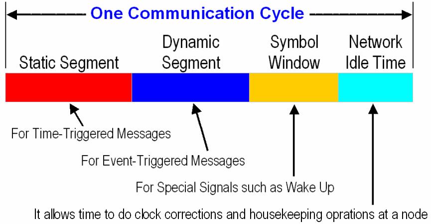
130 Communication Cycle 130
131 Communication Cycle 131
132 Timing Hierarchy 132
133 Microtick Microticks are local time units of a node. The granularity of a node s local time is a microtick. Microticks may have different durations in different nodes. (For example, in one node a mictrotick may be 10 ns and in another node it may be 5 ns.) The microtick is derived directly from the node s oscillator clock tick, optionally making use of a prescaler. 133
134 Macrotick The duration of a macrotick is equal throughout all synchronized nodes in a cluster. Each local macrotick is an integer number of local microticks. The number of microticks per macrotick may vary within the same node due to rate corrections. The number of microticks per macrotick may also differ between nodes, and depends on the oscillator frequency and the prescaler. 134
135 Length of a Communication Cycle (Cycle) A cycle consists of an integer number of macroticks. The number of macroticks per cycle shall be identical in all nodes in a cluster, and remains the same from cycle to cycle. At any given time all nodes should have the same cycle number. 135
136 Timing Hierarchy in a Communication Cycle An action point (AP) is a time instant at which a node performs a specific action, e.g. transmits a frame. 136
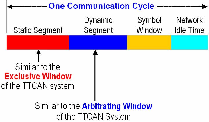
137 Structure of the Static Segment The static segment contains a number of static slots. For a given system, the number of static slots in the static segment is a global constant. All static slots are of same length in terms of macroticks. 137
138 Structure of the Static Segment Every node maintains two slot counters: one for Channel A and one for Channel B. The node simultaneously increments both counters at the end of each static slot. 138
139 Arbitration in the Static Segment Static Slot N is reserved for Frame ID N. If a node detects that its slot counters contain the same value as the Frame ID of one of its queued messages, then it sends that message. Static Slot N of the current cycle will remain idle if the node that contains Frame ID N has no message to send now. 139
140 Fault-Tolerant Transmission in the Static Segment If a node is connected to both channels, then the node can simultaneously send a time-triggered message through both channels. However, if a node is connected to only one channel (say Channel A), then Channel B will remain idle when the node sends a time-triggered message through Channel A. 140
141 Timing within the Static Segment 141
142 Static Slot Length Appropriate configuration of the static slot length (gdstaticslot) must assure that the frame and the channel idle delimiter and any potential safety margin fit within the static slot under worst-case assumptions. 142
143 Structure of the Dynamic Segment The dynamic segment contains a number of minislots. For a given system, the number of minislots in the dynamic segment is a global constant. 143
144 Structure of the Dynamic Segment All minislots are of same length in terms of macroticks. In the dynamic segment the duration of a communication slot depends upon the frame length. 144
145 Arbitration in the Dynamic Segment Each node continues to maintain the two slot counters one for each channel. The slot counters are incremented independently according to the arbitration scheme within the dynamic segment. The slot number of the first minislot in the dynamic segment is the last static slot number plus
146 Timing within the Dynamic Segment 146
147 Timing within the symbol window. Arbitration is not provided by the protocol for the symbol window. The arbitration has to be performed by means of a higher-level protocol. 147
148 Network Idle Time During the network idle time a node calculates and applies clock corrections. The network idle time also serves as a phase during which the node performs implementation specific housekeeping operations. The network idle time contains the remaining number of macroticks within the communication cycle not allocated to the static segment, dynamic segment, or symbol window. 148
149 Frame Encoding in the Static Segment The transmitting node generates a Transmission Start Sequence (TSS) that consists of a continuous LOW for a given period. The Frame Start Sequence (FSS) consists of one HIGH bit. The Byte Start Sequence (BSS) is used to provide timing information to the receiver. The BSS consists of one HIGH bit followed by one LOW bit. The BSS is followed by eight data bits. The Frame End Sequence (FES) marks the last byte of a frame. The FES consists of one LOW bit followed by one HIGH bit. 149
150 Frame Encoding in the Dynamic Segment The Dynamic Trailing Sequence (DTS) is used to indicate the exact point in time of the transmitter s minislot action point. After sending the FES, the transmitter keeps the TxD line low until the next minislot action point. The transmitter then moves the line to the HIGH level. (DTS Variable number of LOW bits + one HIGH bit). 150
151 Sync Nodes and Sync Frames At least three nodes shall be configured to be sync nodes. Sync nodes must be connected to both channels. The sync frames shall be sent in the same static slot in each cycle. Non sync nodes must not transmit frames with the sync frame indicator set. 151
152 Rate Correction The Rate Correction determines by how many microticks the node s cycle length should be increased or decreased. A node determines the length of a communication cycle by taking the difference between the arrival times of a pair of Sync Frames, with the same Frame ID, on consecutive cycles. 152

153 Rate Correction If there are two pairs for a given Sync Frame ID (one pair for channel A and another pair for channel B) the average of the differences is used. The process is repeated for all Sync Frames, and a faulttolerant midpoint algorithm is executed for the correction. 153
.")
154 Offset Correction The offset correction value indicates how many microticks the node should shift the start of its cycle. Negative values mean the NIT should be shortened (making the next cycle start earlier). Positive values mean the NIT should be lengthened (making the next cycle start later). Example: NIT has been shortened 154
155 Offset Correction A node determines the offset of a communication cycle by taking the difference (deviation) between the actual arrival times of a given Sync Frame ID and its expected arrival time. If a given Sync Frame ID has two deviation values (one for channel A and one for channel B) the smaller value is selected. The process is repeated for all Sync Frames, and a faulttolerant midpoint algorithm is executed for the correction. 155
156 Fault-Tolerant Midpoint Algorithm The algorithm determines the value of a parameter, k, based on the number of values in the sorted list. 156
157 Fault-Tolerant Midpoint Algorithm The measured values are sorted and the k largest and the k smallest values are discarded. The largest and the smallest of the remaining values are averaged for the calculation of the midpoint value 157
158 Clock Correction The correction terms are used to adjust the number of microticks in each macrotick 158

159 Wake-Up Signal 159
160 Wakeup of two Channels in a Fault-Tolerant way by Coldstart Nodes 160
161 Startup Wakeup procedure has to be completed before startup can commence. The startup is performed on all channels synchronously. The action of initiating a startup process is called a coldstart. Only a limited number of nodes may initiate a startup, they are called the coldstart nodes. 161
162 Startup When a coldstart node enters startup, it listens to its attached channels and attempts to receive FlexRay frames. If no communication is received, the node commences a coldstart attempt. A coldstart attempt begins with the transmission of a collision avoidance symbol (CAS). The CAS is succeeded by the first regular cycle (Cycle 0: a startup frame). From Cycle 0 on, the node transmits its startup frame. 162
163 Collision Avoidance Symbol (CAS) The Collision Avoidance Symbol (CAS) contains a long train of LOW bits. 163
164 Startup Since each coldstart node is allowed to perform a coldstart attempt, it may occur that several nodes simultaneously transmit the CAS symbol and enter the coldstart path. This situation is resolved during the first four cycles after CAS transmission. As soon as a node that initiates a coldstart attempt receives a CAS symbol or a frame header during these four cycles, it reenters the listen state. Consequently, only one node remains in this path. 164
165 Startup In Cycle 4, other coldstart nodes begin to transmit their startup frames. The node that initiated the coldstart collects all startup frames from Cycle 4 and 5 and performs clock correction. Then the node leaves startup and enters operation. 165
166 Path of the Integrating Coldstart Nodes When a coldstart node enters the startup, it listens to its attached channels and attempts to receive FlexRay frames. If communication is received, it tries to integrate to a transmitting coldstart node. It tries to receive a valid pair of startup frames. If these frame receptions have been successful, it performs clock correction in the following double-cycle. 166
167 Path of the Integrating Coldstart Nodes If clock correction does not signal any errors, it begins to transmit its startup frame; otherwise it reenters the listen state. If for the following three cycles the clock correction does not signal any errors and at least one other coldstart node is visible, the node leaves startup and enters operation. Thereby, it leaves startup at least one cycle after the node that initiated the coldstart. 167
168 Path of a Non-Coldstart Node When a non-coldstart node enters startup, it listens to its attached channels and tries to receive FlexRay frames. If communication is received, it tries to integrate to a transmitting coldstart node. It tries to receive a valid pair of startup frames to derive its schedule and clock correction. 168
169 Path of a Non-Coldstart Node In the following double-cycles, it tries to find at least two coldstart nodes that transmit startup frames. If this fails or if clock correction signals an error, the node aborts the integration attempt and tries anew. 169
170 Path of a Non-Coldstart Node After receiving valid startup frame pairs for two consecutive double-cycles from at least two coldstart nodes, the node leaves startup and enters operation. Thereby, it leaves startup at least two cycles after the node that initiated the coldstart. This means that all nodes of the cluster can leave startup at the end of cycle 7, just before entering cycle
171 State Transitions for the Fault-Free Startup 171
172 172
173 173
174 174
175 175
176 176
177 177
178 THE END 178
179 References 1. Time-Triggered Protocol TTP/C High-Level Specification Document Protocol Version 1.1, TTTech Document Number D-032-S Network Compete for Highway Supremacy, EDN Europe, June Comparison TTP, TTCAN, Flexray by Dr. Markus Plankensteiner, TTTech CAN Protocol Standard, Motorola, Document Number: BCANPSV Overview of CAN, Motorola. 6. Thomas Fuehrer, Bernd Mueller, Florian Hartwich and Robert Hugel, Time-Triggered CAN (TTCAN), Proc. of the SAE 2001 World Congress, Detroit, Michigan, March 5-8, 2001, paper number:
180 References 7. Holger Zeltwanger, Time-Triggered Communication on CAN, Proc. of the SAE 2002 World Congress, Detroit, Michigan, March 4-7, 2002, paper number: FlexRay Communications System Protocol Specification, Version 2.0, June 30, FlexRay Communications System Electrical Physical Layer Specification, Version 2.0, June 30, FlexRay Communications System Bus Guardian Specification, Version 2.0, June 30, Philip Koopman, The FlexRay Protocol, Electrical and Computer Engineering, Carnegie Mellon University. 180
Communication Networks for the Next-Generation Vehicles
 Communication Networks for the, Ph.D. Electrical and Computer Engg. Dept. Wayne State University Detroit MI 48202 (313) 577-3855, smahmud@eng.wayne.edu January 13, 2005 4 th Annual Winter Workshop U.S.
FlexRay International Workshop. Protocol Overview
 FlexRay International Workshop 4 th March 2003 Detroit Protocol Overview Dr. Christopher Temple - Motorola FlexRay principles Provide a communication infrastructure for future generation highspeed control
Comparison of In-Vehicle Communication Protocols for Critical Applications
 IVSS-2005-ARC-03 Comparison of In-Vehicle Communication Protocols for Critical Applications Edward Robert Gundlach and Syed Masud Mahmud Electrical and Computer Engineering Department, Wayne State University,
Distributed Embedded Systems and realtime networks
 STREAM01 / Mastère SE Distributed Embedded Systems and realtime networks Embedded network TTP Marie-Agnès Peraldi-Frati AOSTE Project UNSA- CNRS-INRIA January 2008 1 Abstract Requirements for TT Systems
Field buses (part 2): time triggered protocols
: time triggered protocols") Field buses (part 2): time triggered protocols Nico Fritz Universität des Saarlandes Embedded Systems 2002/2003 (c) Daniel Kästner. 1 CAN and LIN LIN CAN Type Arbitration Transfer rate Serial communication
Field buses (part 2): time triggered protocols Nico Fritz Universität des Saarlandes Embedded Systems 2002/2003 (c) Daniel Kästner. 1 CAN and LIN LIN CAN Type Arbitration Transfer rate Serial communication
FlexRay and Automotive Networking Future
 FlexRay and Automotive Networking Future Chris Quigley Warwick Control Technologies Presentation Overview High Speed and High Integrity Networking Why FlexRay? CAN Problems Time Triggered Network Principles
Systems. Roland Kammerer. 10. November Institute of Computer Engineering Vienna University of Technology. Communication Protocols for Embedded
 Communication Roland Institute of Computer Engineering Vienna University of Technology 10. November 2010 Overview 1. Definition of a protocol 2. Protocol properties 3. Basic Principles 4. system communication
ISO INTERNATIONAL STANDARD. Road vehicles FlexRay communications system Part 2: Data link layer specification
 INTERNATIONAL STANDARD ISO 17458-2 First edition 2013-02-01 Road vehicles FlexRay communications system Part 2: Data link layer specification Véhicules routiers Système de communications FlexRay Partie
16 Time Triggered Protocol
 16 Time Triggered Protocol [TTtech04] (TTP) 18-549 Distributed Embedded Systems Philip Koopman October 25, 2004 Significant material drawn from: Prof. H. Kopetz [Kopetz] TTP Specification v 1.1 [TTTech]
An Introduction to FlexRay as an Industrial Network
 An Introduction to FlexRay as an Industrial Network Robert Shaw, Brendan Jackman Automotive Control Group, Waterford Institute of Technology, Waterford, Ireland. E-mail: rshaw@wit.ie, bjackman@wit.ie Website:
In-Vehicle Network Architecture for the Next-Generation Vehicles SAE TECHNICAL PAPER SERIES
 2005-01-1531 SAE TECHNICAL PAPER SERIES In- Network Architecture for the Next-Generation s Syed Masud Mahmud Department of Electrical & Computer Engineering, Wayne State University Sheran Alles Ford Motor
Today. Last Time. Motivation. CAN Bus. More about CAN. What is CAN?
 Embedded networks Characteristics Requirements Simple embedded LANs Bit banged SPI I2C LIN Ethernet Last Time CAN Bus Intro Low-level stuff Frame types Arbitration Filtering Higher-level protocols Today
Controller Area Network (CAN)
") Controller Area Network (CAN) EECS 461, Fall 2008 J. A. Cook J. S. Freudenberg 1 Introduction Up until now, we ve considered our embedded control system to be self-contained: an algorithm implemented in
Controller Area Network (CAN) EECS 461, Fall 2008 J. A. Cook J. S. Freudenberg 1 Introduction Up until now, we ve considered our embedded control system to be self-contained: an algorithm implemented in
A Fault Management Protocol for TTP/C
 A Fault Management Protocol for TTP/C Juan R. Pimentel Teodoro Sacristan Kettering University Dept. Ingenieria y Arquitecturas Telematicas 1700 W. Third Ave. Polytechnic University of Madrid Flint, Michigan
FlexRay Communications System. Preliminary Central Bus Guardian Specification. Version 2.0.9
 FlexRay Communications System Preliminary Central Bus Guardian Specification Version 2.0.9 Disclaimer This specification as released by the FlexRay Consortium is intended for the purpose of information
FlexRay Requirements Specification
 FlexRay - Requirements Specification FlexRay Requirements Specification Authors: Ralf Belschner 2, Josef Berwanger 1, Christian Ebner 1, Harald Eisele 4, Sven Fluhrer 2, Thomas Forest 4, Thomas Führer
BOSCH. CAN Specification. Version , Robert Bosch GmbH, Postfach , D Stuttgart
 CAN Specification Version 2.0 1991, Robert Bosch GmbH, Postfach 30 02 40, D-70442 Stuttgart CAN Specification 2.0 page 1 Recital The acceptance and introduction of serial communication to more and more
FlexRay. Requirements Specification. Version 2.1
 FlexRay Requirements Specification Version 2.1. Revision History DISCLAIMER This specification as released by the FlexRay Consortium is intended for the purpose of information only. The use of material
Real-Time (Paradigms) (47)
 (47)") Real-Time (Paradigms) (47) Memory: Memory Access Protocols Tasks competing for exclusive memory access (critical sections, semaphores) become interdependent, a common phenomenon especially in distributed
Real-Time (Paradigms) (47) Memory: Memory Access Protocols Tasks competing for exclusive memory access (critical sections, semaphores) become interdependent, a common phenomenon especially in distributed
Course Introduction. Purpose. Objectives. Content. Learning Time
 Course Introduction Purpose This training course provides an overview of Message Frames and hardware issues of the Controller Area Network (CAN) technology used to build networked, multiprocessor embedded
Fault tolerant TTCAN networks
 Fault tolerant TTCAN networks B. MŸller, T. FŸhrer, F. Hartwich, R. Hugel, H. Weiler, Robert Bosch GmbH TTCAN is a time triggered layer using the CAN protocol to communicate in a time triggered fashion.
Content. Deterministic Access Polling(1) Master-Slave principles: Introduction Layer 2: Media Access Control
 Master-Slave principles: Introduction Layer 2: Media Access Control") Content Introduction Layer 2: Frames Error Handling Media Access Control General approaches and terms Network Topologies Media Access Principles (Random) Aloha Principles CSMA, CSMA/CD, CSMA / CA Media
Content Introduction Layer 2: Frames Error Handling Media Access Control General approaches and terms Network Topologies Media Access Principles (Random) Aloha Principles CSMA, CSMA/CD, CSMA / CA Media
Sharif University of Technology, Tehran, Iran
 EVALUATION OF BABBLING IDIOT FAILURES IN FLEXRAY-BASED NETWORKES * Vahid Lari, Mehdi Dehbashi, Seyed Ghassem Miremadi, Mojtaba Amiri Sharif University of Technology, Tehran, Iran Abstract: This paper evaluates
APPLICATIONS FLEXRAY AND ITS WILEY REAL TIME MULTIPLEXED NETWORK. Dominique Paret. dp-consulting, Paris, France. Claygate, Esher, UK
 FLEXRAY AND ITS APPLICATIONS REAL TIME MULTIPLEXED NETWORK Dominique Paret dpconsulting, Paris, France Translated by Bill Chilcott Fellow of the Institute of Translation and Interpreting Claygate, Esher,
Flexray Communication Controller for Intra-Vehicular Communication and Its Realization in FPGA
 2016 IJSRSET Volume 2 Issue 1 Print ISSN : 2395-1990 Online ISSN : 2394-4099 Themed Section: Engineering and Technology Flexray Communication Controller for Intra-Vehicular Communication and Its Realization
Dependable Computer Systems
 Dependable Computer Systems Part 6b: System Aspects Contents Synchronous vs. Asynchronous Systems Consensus Fault-tolerance by self-stabilization Examples Time-Triggered Ethernet (FT Clock Synchronization)
CAN-FD Flexible Data Rate CAN
 FD CAN-FD Flexible Data Rate CAN A Short Primer and Update V. 202-08-27 Agenda > Why CAN-FD? What is CAN-FD? Basic Concepts CAN-FD Specifics Data Frame Operating Modes/States Physical Layer Considerations
EP A1 (19) (11) EP A1 (12) EUROPEAN PATENT APPLICATION. (43) Date of publication: Bulletin 2012/45
 (11) EP A1 (12) EUROPEAN PATENT APPLICATION. (43) Date of publication: Bulletin 2012/45") (19) (12) EUROPEAN PATENT APPLICATION (11) EP 2 521 319 A1 (43) Date of publication: 07.11.2012 Bulletin 2012/45 (51) Int Cl.: H04L 12/40 (2006.01) H04L 1/00 (2006.01) (21) Application number: 11164445.6
(19) (12) EUROPEAN PATENT APPLICATION (11) EP 2 521 319 A1 (43) Date of publication: 07.11.2012 Bulletin 2012/45 (51) Int Cl.: H04L 12/40 (2006.01) H04L 1/00 (2006.01) (21) Application number: 11164445.6
Operating Systems, Concurrency and Time. real-time communication and CAN. Johan Lukkien
 Operating Systems, Concurrency and Time real-time communication and CAN Johan Lukkien (Courtesy: Damir Isovic, Reinder Bril) Question Which requirements to communication arise from real-time systems? How
Controller area network
 Controller area network From Wikipedia, the free encyclopedia (Redirected from Controller area network) Controller area network (CAN or CAN-bus) is a vehicle bus standard designed to allow microcontrollers
Recommended readings
 Recommended readings Dominique Paret, Multiplexed Networks for Embedded Systems: CAN, LIN, FlexRay, Safe-by-Wire..., ISBN: 978-0- 470-03416-3, 434 pages, WILEY, UK, 2007. Wolfhard Lawrenz, CAN System Engineering:
Using CAN Arbitration for Electrical Layer Testing
 Using CAN Arbitration for Electrical Layer Testing Sam Broyles and Steve Corrigan, Texas Instruments, Inc. The Controller Area Network (CAN) protocol incorporates a powerful means of seamlessly preventing
Controller Area Network
 Controller Area Network 1 CAN FUNDAMENTALS...3 1.1 USER BENEFITS...3 1.1.1 CAN is low cost...3 1.1.2 CAN is reliable...3 1.1.3 CAN means real-time...3 1.1.4 CAN is flexible...3 1.1.5 CAN means Multicast
Automotive and highly dependable Networks!
 Automotive and highly dependable Networks H. Kopetz, TU Wien (see references in the introduction) Excellent surveys: TTP: Hermann Kopetz, Günther Bauer: "The Time-Triggered Architecture" http://www.tttech.com/technology/docs/history/hk_2002-10-tta.pdf
Understanding and Using the Controller Area Network Communication Protocol
 Marco Di Natale Haibo Zeng Paolo Giusto Arkadeb Ghosal Understanding and Using the Controller Area Network Communication Protocol Theory and Practice ^Spri ringer Contents..? 1 The CAN 2.0b Standard 1
Timing in the TTCAN Network
 Timing in the Network Florian Hartwich, Bernd Müller, Thomas Führer, Robert Hugel, Robert Bosch GmbH ISO TC22/SC3/WG1/TF6 has standardised (as ISO CD 11898-4) an additional layer to the CAN protocol, Time
Communication in Avionics
 Communication in Avionics 1 Outline Basic Overview Communication architectures Event Triggered Time Triggered Communication architecture examples Case Study: How Data Communication Affects Scheduling 2
ISO INTERNATIONAL STANDARD. Road vehicles FlexRay communications system Part 4: Electrical physical layer specification
 INTERNATIONAL STANDARD ISO 17458-4 First edition 2013-02-01 Road vehicles FlexRay communications system Part 4: Electrical physical layer specification Véhicules routiers Système de communications FlexRay
Institutionen för datavetenskap Department of Computer and Information Science
 Institutionen för datavetenskap Department of Computer and Information Science Final thesis A SystemC simulator for the dynamic segment of the FlexRay protocol by Venkata Rama Krishna Reddy Podduturi LIU-IDA/LITH-EX-A--/9--SE
FlexRay controller. Author: Martin Paták
 FlexRay controller Author: Martin Paták Prague, 2012 Contents 1 FlexRay controller 1 1.1 Overview.................................... 1 1.2 Interface.................................... 2 1.2.1 Overview...............................
DEFINITION AND IMPLEMENTATION OF AN ARCHITECTURAL CONCEPT FOR CONFIGURING A CAN NETWORK
 Bachelor's thesis Degree Programme in Information Technology Internet Technology 2015 Daria Shevchenko DEFINITION AND IMPLEMENTATION OF AN ARCHITECTURAL CONCEPT FOR CONFIGURING A CAN NETWORK BACHELOR S
Fault Effects in FlexRay-Based Networks with Hybrid Topology
 The Third International Conference on Availability, Reliability and Security Fault Effects in -Based Networks with Hybrid Topology Mehdi Dehbashi, Vahid Lari, Seyed Ghassem Miremadi, Mohammad Shokrollah-Shirazi
Probabilistic Worst-Case Response-Time Analysis for the Controller Area Network
 Probabilistic Worst-Case Response-Time Analysis for the Controller Area Network Thomas Nolte, Hans Hansson, and Christer Norström Mälardalen Real-Time Research Centre Department of Computer Engineering
Serial Buses in Industrial and Automotive Applications
 Serial Buses in Industrial and Automotive Applications Presented by Neelima Chaurasia Class: #368 1 Overview As consumer electronics, computer peripherals, vehicles and industrial applications add embedded
Embedded Systems. 8. Communication
 Embedded Systems 8. Communication Lothar Thiele 8-1 Contents of Course 1. Embedded Systems Introduction 2. Software Introduction 7. System Components 10. Models 3. Real-Time Models 4. Periodic/Aperiodic
Automotive and industrial use cases for CAN FD
 Improved CAN Automotive and industrial use cases for CAN FD Dr. Tobias Lorenz Author Dr. Tobias Lorenz Etas GmbH PO Box 300220 DE-70442 Stuttgart Tel.: +49-711-89661-0 Fax: +49-711-89661-107 tobias.lorenz@etas.com
Chapter 39: Concepts of Time-Triggered Communication. Wenbo Qiao
 Chapter 39: Concepts of Time-Triggered Communication Wenbo Qiao Outline Time and Event Triggered Communication Fundamental Services of a Time-Triggered Communication Protocol Clock Synchronization Periodic
This document is a preview generated by EVS
 INTERNATIONAL STANDARD ISO 17458-2 First edition 2013-02-01 Road vehicles FlexRay communications system Part 2: Data link layer specification Véhicules routiers Système de communications FlexRay Partie
CAN protocol enhancement
 Protocols CAN protocol enhancement This article describes the enhanced CAN protocol called CAN-HG and the features of the IC circuitry from Canis that implement it. CAN-HG has been designed to meet two
Performance improvements of automobile communication protocols in electromagnetic interference environments
 Scholars' Mine Masters Theses Student Research & Creative Works Fall 2007 Performance improvements of automobile communication protocols in electromagnetic interference environments Fei Ren Follow this
FlexRay Analysis, Configuration Parameter Estimation, and Adversaries
 FlexRay Analysis, Configuration Parameter Estimation, and Adversaries Markus Iversen Huse Master of Science in Cybernetics and Robotics Submission date: June 2017 Supervisor: Sverre Hendseth, ITK Norwegian
Additional Slides (informative)
") Automation Systems Discrete Event Control Systems and Networked Automation Systems Additional Slides (informative) Application Automotive Networks (LIN, CAN, FlexRay, MOST) Vorlesungstitel Vehicle Bus
Automation Systems Discrete Event Control Systems and Networked Automation Systems Additional Slides (informative) Application Automotive Networks (LIN, CAN, FlexRay, MOST) Vorlesungstitel Vehicle Bus
An Introduction to CAN by Peter Bagschik (I+ME ACTIA)
") 1 of 11 24.10.00 14:36 An Introduction to CAN by Peter Bagschik (I+ME ACTIA) The CAN (Controller Area Network) protocol was developed in Europe for the use in passenger cars. Through the successful use
1 of 11 24.10.00 14:36 An Introduction to CAN by Peter Bagschik (I+ME ACTIA) The CAN (Controller Area Network) protocol was developed in Europe for the use in passenger cars. Through the successful use
MCP2510. MCP2510 Rev. AA Silicon Errata Sheet. 3. Module: Error Flags. 1. Module: Configuration Mode State Machine. 4. Module: Bus Timing Logic
 M MCP2510 MCP2510 Rev. AA Silicon Errata Sheet The MCP2510 parts you have received conform functionally to the Device Data Sheet (DS21291C), except for the anomalies described below. All of the problems
Time-Triggered Ethernet
 Time-Triggered Ethernet Chapters 42 in the Textbook Professor: HONGWEI ZHANG CSC8260 Winter 2016 Presented By: Priyank Baxi (fr0630) fr0630@wayne.edu Outline History Overview TTEthernet Traffic Classes
ESCAN An Open Source, High Bandwidth, Event Scheduled Controller Area Network
 ESCAN An Open Source, High Bandwidth, Event Scheduled Controller Area Network A. Williams, C. Quigley, R. McLaughlin, Warwick Control Event Scheduled CAN (ESCAN) is an open source, scheduling protocol
CAN Network with Time Triggered Communication
 CAN Network with Time Triggered Communication Florian Hartwich Bernd Müller Thomas Führer Robert Hugel Robert Bosch GmbH The communication in the classic CAN network is event triggered; peak loads may
CAN with Flexible Data-Rate
 CAN with Flexible Data-Rate Florian Hartwich, Robert Bosch GmbH Ever increasing bandwidth requirements in automotive networks impede the applicability of CAN due to its bit rate limitation to 1 MBit/s.
An Encapsulated Communication System for Integrated Architectures
 An Encapsulated Communication System for Integrated Architectures Architectural Support for Temporal Composability Roman Obermaisser Overview Introduction Federated and Integrated Architectures DECOS Architecture
Freescale Semiconductor, I. SECTION 13 CAN 2.0B CONTROLLER MODULE (TouCAN)
") nc. SECTION 13 CAN 2.0B CONTROLLER MODULE (TouCAN) This section is an overview of the TouCAN module. Refer to D.10 TouCAN Module for information concerning TouCAN address map and register structure. 13.1
nc. SECTION 13 CAN 2.0B CONTROLLER MODULE (TouCAN) This section is an overview of the TouCAN module. Refer to D.10 TouCAN Module for information concerning TouCAN address map and register structure. 13.1
Workshop on In Vehicle Network using CAN By
 Workshop on In Vehicle Network using CAN By Modern CAR Modern CAR INTRODUCTION 1. Controller Area Network (CAN) was initially created by German automotive system supplier Robert Bosch in the mid-1980s.
A Reliable Gateway for In-vehicle Networks
 Proceedings of the 17th World Congress The International Federation of Automatic Control A Reliable Gateway for In-vehicle Networks S. H. Seo*, J. H. Kim*, T. Y. Moon* S. H. Hwang**, K. H. Kwon*, J. W.
A CAN-Based Architecture for Highly Reliable Communication Systems
 A CAN-Based Architecture for Highly Reliable Communication Systems H. Hilmer Prof. Dr.-Ing. H.-D. Kochs Gerhard-Mercator-Universität Duisburg, Germany E. Dittmar ABB Network Control and Protection, Ladenburg,
Your favorite blog :www.vijay-jotani.weebly.com (popularly known as VIJAY JOTANI S BLOG..now in facebook.join ON FB VIJAY
 VISIT: Course Code : MCS-042 Course Title : Data Communication and Computer Network Assignment Number : MCA (4)/042/Assign/2014-15 Maximum Marks : 100 Weightage : 25% Last Dates for Submission : 15 th
CAN Protocol Implementation
 CAN Protocol Implementation Arun Pasupathi, Gaurav Agalave Electrical and Computer Engineering Department School of Engineering and Computer Science Oakland University, Rochester, MI e-mails: apasupathi@oakland.edu,
Communication (III) Kai Huang
 Kai Huang") Communication (III) Kai Huang Ethernet Turns 40 12/17/2013 Kai.Huang@tum 2 Outline Bus basics Multiple Master Bus Network-on-Chip Examples o SPI o CAN o FlexRay o Ethernet Basic OSI model Real-Time Ethernet
Communication (III) Kai Huang Ethernet Turns 40 12/17/2013 Kai.Huang@tum 2 Outline Bus basics Multiple Master Bus Network-on-Chip Examples o SPI o CAN o FlexRay o Ethernet Basic OSI model Real-Time Ethernet
Real-Time Communications. LS 12, TU Dortmund
 Real-Time Communications Prof. Dr. Jian-Jia Chen LS 12, TU Dortmund 20, Jan., 2016 Prof. Dr. Jian-Jia Chen (LS 12, TU Dortmund) 1 / 29 Random Access no access control; requires low medium utilization Prof.
CS 123: Lecture 12, LANs, and Ethernet. George Varghese. October 24, 2006
 CS 123: Lecture 12, LANs, and Ethernet George Varghese October 24, 2006 Selective Reject Modulus failure Example w = 2, Max = 3 0 0 1 3 0 A(1) A(2) 1 0 retransmit A(1) A(2) buffer Case 1 Case 2 reject
Gryphon Hardware Information: Dual SJA1000 Fault Tolerant CAN card
 Gryphon Hardware Information: Dual SJA1000 Fault Tolerant CAN card External HD-15 connector pinout Note: We recommend that you not hot swap the connector on this module. We recommend that you turn off
A Time-Triggered Ethernet (TTE) Switch
 Switch") A Time-Triggered Ethernet () Switch Klaus Steinhammer Petr Grillinger Astrit Ademaj Hermann Kopetz Vienna University of Technology Real-Time Systems Group Treitlstr. 3/182-1, A-1040 Vienna, Austria E-mail:{klaus,grilling,ademaj,hk}@vmars.tuwien.ac.at
A Time-Triggered Ethernet () Switch Klaus Steinhammer Petr Grillinger Astrit Ademaj Hermann Kopetz Vienna University of Technology Real-Time Systems Group Treitlstr. 3/182-1, A-1040 Vienna, Austria E-mail:{klaus,grilling,ademaj,hk}@vmars.tuwien.ac.at
The House Intelligent Switch Control Network based On CAN bus
 The House Intelligent Switch Control Network based On CAN bus A.S.Jagadish Department Electronics and Telecommunication Engineering, Bharath University Abstract The Embedded Technology is now in its prime
Links. CS125 - mylinks 1 1/22/14
 Links 1 Goals of Today s Lecture Link-layer services Encoding, framing, and error detection Error correction and flow control Sharing a shared media Channel partitioning Taking turns Random access Shared
Medium Access Control. IEEE , Token Rings. CSMA/CD in WLANs? Ethernet MAC Algorithm. MACA Solution for Hidden Terminal Problem
 Medium Access Control IEEE 802.11, Token Rings Wireless channel is a shared medium Need access control mechanism to avoid interference Why not CSMA/CD? 9/15/06 CS/ECE 438 - UIUC, Fall 2006 1 9/15/06 CS/ECE
Flexray Protocol in Automotive Network Communications
 Flexray Protocol in Automotive Network Communications 1. Anjan Kumar B S, 2. Arpitha Rani R, 3. Keya Priyambada, 4. Arti Kumari 1. Asst.Professor, Department of Instrumentation Technology, Bangalore Institute
Model Checking the FlexRay Physical Layer Protocol
 Model Checking the FlexRay Physical Layer Protocol Michael Gerke Reactive Systems Group Saarland University Germany 25.09.2013 If you hit the brakes... ... and they don t work: Brakes should work! Drive-by-Wire
A Comparison of TTP/C and FlexRay
 1 A Comparison of TTP/C and FlexRay Research Report 10/2001 5 10 H. Kopetz hk@vmars.tuwien.ac.at Institut für Technische Informatik Technische Universität Wien, Austria May 9, 2001 15 20 25 30 Abstract:
Multiple Access Protocols
 Multiple Access Protocols Computer Networks Lecture 2 http://goo.gl/pze5o8 Multiple Access to a Shared Channel The medium (or its sub-channel) may be shared by multiple stations (dynamic allocation) just
Data Link Layer Technologies
 Chapter 2.2 La 2 Data Link La Technologies 1 Content Introduction La 2: Frames Error Handling 2 Media Access Control General approaches and terms Aloha Principles CSMA, CSMA/CD, CSMA / CA Master-Slave
Introduction to Controller Area Network (CAN)
") Introduction to Controller Area Network (CAN) 2003 Microchip Technology Incorporated. All Rights Reserved. Introduction to Controller Area Network (CAN) 1 Topics CAN Protocol Overview What is CAN? CAN
Introduction to Controller Area Network (CAN) 2003 Microchip Technology Incorporated. All Rights Reserved. Introduction to Controller Area Network (CAN) 1 Topics CAN Protocol Overview What is CAN? CAN
Intelligent Transportation Systems. Medium Access Control. Prof. Dr. Thomas Strang
 Intelligent Transportation Systems Medium Access Control Prof. Dr. Thomas Strang Recap: Wireless Interconnections Networking types + Scalability + Range Delay Individuality Broadcast o Scalability o Range
IEEE , Token Rings. 10/11/06 CS/ECE UIUC, Fall
 IEEE 802.11, Token Rings 10/11/06 CS/ECE 438 - UIUC, Fall 2006 1 Medium Access Control Wireless channel is a shared medium Need access control mechanism to avoid interference Why not CSMA/CD? 10/11/06
Data Link Layer: Overview, operations
 Data Link Layer: Overview, operations Chapter 3 1 Outlines 1. Data Link Layer Functions. Data Link Services 3. Framing 4. Error Detection/Correction. Flow Control 6. Medium Access 1 1. Data Link Layer
Fault Tolerance Tradeoffs in Moving from Decentralized to Centralized Embedded Systems
 Fault Tolerance Tradeoffs in Moving from Decentralized to Centralized Embedded Systems Jennifer Morris ECE Department Carnegie Mellon University jenmorris@cmu.edu Daniel Kroening CS Department Carnegie
CAN in Space workshop
 CAN in Space workshop Holger Zeltwanger www.can-cia.org The next generation of CAN technology: Chances and challenges of CAN FD Presentation outline u Introduction into CAN FD u CAN FD physical layer u
High Level View. EE 122: Ethernet and Random Access protocols. Medium Access Protocols
 High Level View EE 122: Ethernet and 802.11 Ion Stoica September 18, 2002 Goal: share a communication medium among multiple hosts connected to it Problem: arbitrate between connected hosts Solution goals:
Topics. Link Layer Services (more) Link Layer Services LECTURE 5 MULTIPLE ACCESS AND LOCAL AREA NETWORKS. flow control: error detection:
 Link Layer Services LECTURE 5 MULTIPLE ACCESS AND LOCAL AREA NETWORKS. flow control: error detection:") 1 Topics 2 LECTURE 5 MULTIPLE ACCESS AND LOCAL AREA NETWORKS Multiple access: CSMA/CD, CSMA/CA, token passing, channelization LAN: characteristics, i basic principles i Protocol architecture Topologies
1 Topics 2 LECTURE 5 MULTIPLE ACCESS AND LOCAL AREA NETWORKS Multiple access: CSMA/CD, CSMA/CA, token passing, channelization LAN: characteristics, i basic principles i Protocol architecture Topologies
Theory, Concepts and Applications
 Theory, Concepts and Applications ETR 2015 Rennes August, the 27 th Jean-Baptiste Chaudron jean-baptiste.chaudron@tttech.com Copyright TTTech Computertechnik AG. All rights reserved. Page 1 AGENDA Introduction
Links Reading: Chapter 2. Goals of Todayʼs Lecture. Message, Segment, Packet, and Frame
 Links Reading: Chapter 2 CS 375: Computer Networks Thomas Bressoud 1 Goals of Todayʼs Lecture Link-layer services Encoding, framing, and error detection Error correction and flow control Sharing a shared
DeviceNet - CIP on CAN Technology
 The CIP Advantage Technology Overview Series DeviceNet - CIP on CAN Technology DeviceNet has been solving manufacturing automation applications since the mid-1990's, and today boasts an installed base
Lecture 2. Basics of networking in automotive systems: Network. topologies, communication principles and standardised protocols
 Lecture 2. Basics of networking in automotive systems: Network topologies, communication principles and standardised protocols Objectives Introduce basic concepts used in building networks for automotive
Multiple Access Links and Protocols
 Multiple Access Links and Protocols Two types of links : point-to-point PPP for dial-up access point-to-point link between Ethernet switch and host broadcast (shared wire or medium) old-fashioned Ethernet
EE 122: Ethernet and
 EE 122: Ethernet and 802.11 Ion Stoica September 18, 2002 (* this talk is based in part on the on-line slides of J. Kurose & K. Rose) High Level View Goal: share a communication medium among multiple hosts
Presented by: Murad Kaplan
 Presented by: Murad Kaplan Introduction. Design of SCP-MAC. Lower Bound of Energy Performance with Periodic Traffic. Protocol Implementation. Experimental Evaluation. Related Work. 2 Energy is a critical
Developing deterministic networking technology for railway applications using TTEthernet software-based end systems
 Developing deterministic networking technology for railway applications using TTEthernet software-based end systems Project n 100021 Astrit Ademaj, TTTech Computertechnik AG Outline GENESYS requirements
Design and Quantitative Evaluation of a Novel FlexRay Bus Guardian
 Design and Quantitative Evaluation of a Novel FlexRay Bus Guardian Kai Wang, Aidong Xu, and Hong Wang Key Laboratory of Industrial Informatics Shenyang Institute of Automation, Chinese Academy of Sciences
Redes de Computadores. Medium Access Control
 Redes de Computadores Medium Access Control Manuel P. Ricardo Faculdade de Engenharia da Universidade do Porto 1 » How to control the access of computers to a communication medium?» What is the ideal Medium
Design For High Performance Flexray Protocol For Fpga Based System
 IOSR Journal of VLSI and Signal Processing (IOSR-JVSP) e-issn: 2319 4200, p-issn No. : 2319 4197 PP 83-88 www.iosrjournals.org Design For High Performance Flexray Protocol For Fpga Based System E. Singaravelan
Scheduling Mechanisms for SpaceWire Networks
 Scheduling Mechanisms for SpaceWire Networks Ilya Korobkov, Elena Podgornova, Dmitry Raszhivin, Valentin Olenev, Irina Lavrovskaya {ilya.korobkov, alena.podgornova, dmitry.raszhivin, valentin.olenev, irina.lavrovskaya}@guap.ru
Computation of CAN Bit Timing Parameters Simplified
 Computation of CAN Bit Timing Parameters Simplified Meenanath Taralkar, OTIS ISRC PVT LTD, Pune, India CAN bit timing and synchronization play an important role in ensuring performance of CAN network.
X-by-wire systems and time-triggered protocols
 1(43) X-by-wire systems and 2(43) ABSTRACT Electronic systems in vehicles are becoming more and more common. X-by-wire systems are electronic systems without mechanical backup where the x stands for safety