MODIFYING THE ACS355 UL TYPE 4X FOR MXXX OPTIONS
|
|
|
- Ethel Norton
- 5 years ago
- Views:
Transcription
1 MODIFYING THE ACS355 UL TYPE 4X FOR MXXX OPTIONS Description: The following instructions are designed to provide a step by step procedure; how to modify the ACS355 UL Type 4X drive for Mxxx-01 (MPOW-01, MREL-01 or MTAC-01) option. If these procedures are followed and executed properly all standard product warranties apply. 1.1 Table of Contents 1.1 Table of Contents General Information Description Safety in Installation and Maintenance Reference Documentation Remove & Modify the UL Type 4X Drive Cover Using a dremel tool cut the power and fault indicator extension tab approximately a 3/16 from the cover surface Modify Mxxx-01 (MPOW-01, MREL-01, MTAC-01) for UL Type 4X drive mounting Using a screw driver release the four securing tabs and then remove the top cover Install Mxxx-01 to ACS355 U.L Type 4X Drive Remove the standoff and screw from the Mxxx-01 Kit Remove the circuit board fastening screw from the drive and insert and tighten the Mxxx-01 standoff Install the Mxxx-01 option onto the drive and secure using the screw provided with the Mxxx- 01 kit Control Panel Access Option & Reassemble Option 1 Built-In Control Panel Disconnected Note: Option 1 will require removing the ACS355 s UL Type 4x front cover to connect the drives control panel Option 2 Blank Control Panel - Note: Option 2 will require removing the control panel access cover to connect the drives control panel. The control panel will have to be stored external to the drive.... 7
2 2 General Information 2.1 Description The following instructions are designed to provide a step by step procedure; how to modify the ACS355 UL Type 4X drive for Mxxx-01 (MPOW-01, MREL-01 or MTAC-01) option. If these procedures are followed and executed properly all standard product warranties apply. 2.2 Safety in Installation and Maintenance Refer to the safety section in the ACS355 User s Manuals listed below. Warning! Only qualified electricians are allowed to install and maintain the drive! Never work on the drive, motor cable or motor when input power is applied. After disconnecting the input power, always wait for 5 minutes to let the intermediate circuit capacitors discharge before you start working on the drive, motor or motor cable. Always ensure by measuring with a multimeter that 1. There is no voltage between the drive input phases U1, V1, W1 and the ground. 2. There is no voltage between BRK+ and BRK- and the ground. 2.3 Reference Documentation Description ACS355 User's manual ACS355 UL Type 4X Supplement User s Manual Doc Number 3AUA AUA

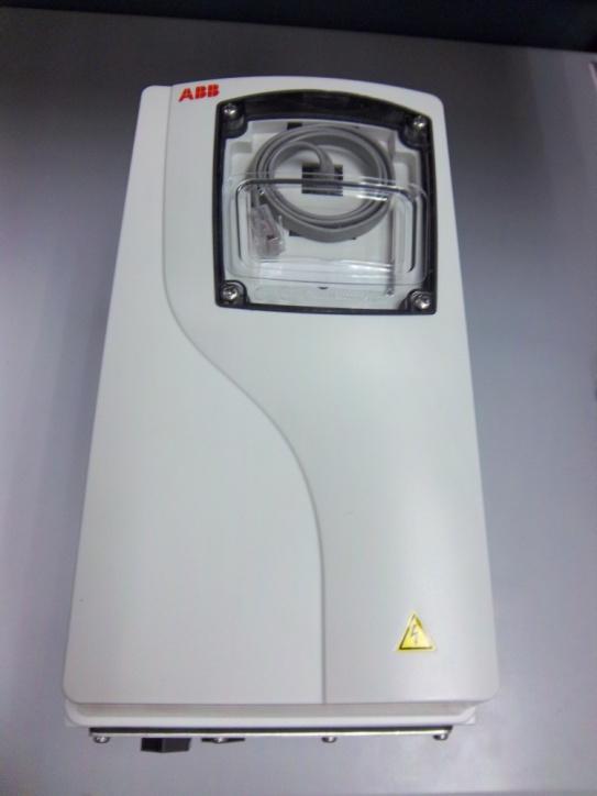
3 3 Remove & Modify the UL Type 4X Drive Cover Loosen the four capsulated screws and remove cover Remove CAT5 cable from the drives cover strain relief tabs and RJ-45 connector Remove CAT 5 cable from the drives RJ-45 connector.


 for UL Type")

4 3.2 Using a dremel tool cut the power and fault indicator extension tab approximately a 3/16 from the cover surface. Original Modified 4 Modify Mxxx-01 (MPOW-01, MREL-01, MTAC-01) for UL Type 4X drive mounting. 4.1 Using a screw driver release the four securing tabs and then remove the top cover. Original Modified
5


6 5 Install Mxxx-01 to ACS355 U.L Type 4X Drive 5.1 Remove the standoff and screw from the Mxxx-01 Kit. 5.2 Remove the circuit board fastening screw from the drive and insert and tighten the Mxxx-01 standoff. 5.3 Install the Mxxx-01 option onto the drive and secure using the screw provided with the Mxxx-01 kit.

7 6 Control Panel Access Option & Reassemble 6.1 Option 1 Built-In Control Panel Disconnected Note: Option 1 will require removing the ACS355 s UL Type 4x front cover to connect the drives control panel. 7 Place cover and gasket on ACS355 UL Type 4X drive and tighten the four fastening screws. Procedure is complete. 7.1 Option 2 Blank Control Panel - Note: Option 2 will require removing the control panel access cover to connect

8 the drives control panel. The control panel will have to be stored external to the drive Remove the control panel access cover Remove the control panel from the cradle Place a blank label over the Power and Fault designators Plug CAT 5 cable into the drives RJ45 connector Feed the CAT 5 cable through the control panel access hole in the UL Type 4X front cover Place UL Type 4X front cover and gasket on the ACS355 UL Type Neatly coil the CAT5 cable in the cradle Install the control panel access cover Tighten the four fastening screws. Procedure is complete.
9
WARNING ELECTRICAL SHOCK HAZARD
 Description Safety Instructions The top-entry sub D9 connector kit is designed for enclosure sizes D1h D8h, E1 E2, and E1h E4h with VLT PROFIBUS DP MCA 101 option. It fits the following drives: VLT HVAC
Series 3700 Screw Terminal Assemblies Installation Instructions
 Keithley Instruments, Inc. 28775 Aurora Road Cleveland, Ohio 44139 1-888-KEITHLEY www.keithley.com Series 3700 Screw Terminal Assemblies Installation Instructions Introduction This document contains handling
Installing a Power over Ethernet injector
 Installing a Power over Ethernet injector AlphaEclipse StreetSmart and RoadStar signs The instructions in this document explain how to install/replace a Power over Ethernet (PoE) injector in a StreetSmart
XDBKITS5 Bus / DB Terminal Kit (Size 5) Installation Manual DPD00116
 Installation Manual DPD00116") XDBKITS5 Bus / DB Terminal Kit (Size 5) Installation Manual DPD00116 XDBKITS5 Option Kit Installation Manual vacon 3 Installing the Bus / DB Terminal Option Kit Introduction The XDBKITS5 option kit is
XDBKITS5 Bus / DB Terminal Kit (Size 5) Installation Manual DPD00116 XDBKITS5 Option Kit Installation Manual vacon 3 Installing the Bus / DB Terminal Option Kit Introduction The XDBKITS5 option kit is
E1135C PDU and Pod Upgrade Procedure
 E4030-90010 Rev. B 12/2003 In this Document... Tools Needed, 2 Contents of the Upgrade Kits, 2 Installation Procedures, 4 Verifying the Power Option of the New PDU, 4 Removing the PDU from the Support
Model 2460-KIT. Screw Terminal Connector Kit. Description / September 2014 *P * 1
 Keithley Instruments 28775 Aurora Road Cleveland, Ohio 44139 1-800-935-5595 http://www.keithley.com Model 2460-KIT Screw Terminal Connector Kit Description The Model 2460-KIT Screw Terminal Connector Kit
PEREGRINE SERIES RETROFIT INSTALLATION GUIDE
 06.05.17 HanleyLED H100W-PPS524V Spec Sheet SOLUTIONS THAT MAKE SENSE PEREGRINE SERIES RETROFIT INSTALLATION GUIDE Light Up New Markets Your Local Distributor: Grimco US www.grimco.com 800.542.9941 Canada
Installation Guide. Retrofit Kit for USB Ready Intraoral Systems
 Installation Guide Retrofit Kit for USB Ready Intraoral Systems Table of Contents Wall-Mount Retrofit Kit... 2 Introduction... 2 Connecting the Articulating and Horizontal Arm Cables... 2 Installing the
Phase Loss Protection Upgrade. Phase Loss Protection Upgrade. In this bulletin:
 Phase Loss Protection Upgrade In this bulletin: Introduction... 2 Purpose... 2 General... 2 Applicability... 2 HD3070 Phase Loss Protection Upgrade Kit Parts... 2 Preparation... 4 Install the Phase Loss
GPIB-232CT-A IBCL EPROM Installation Guide
 NATIONAL INSTRUMENTS The Software is the Instrument Installation Guide GPIB-232CT-A IBCL EPROM Installation Guide This guide describes how to replace the factory-installed EPROM that comes with your GPIB-232CT-A.
Replacing the Power Supply
 APPENDIX B This appendix includes information on how to replace the power supply for the Cisco AS550XM universal gateway and contains the following sections: Safety Recommendations, page B-1 Required Tools
User s Manual. ACS550-PD 3R Irrigation Packaged Drive Supplement to ACS550-U1 User s Manual
 User s Manual ACS550-PD 3R Irrigation Packaged Drive Supplement to ACS550-U1 User s Manual 2 ACS550-PD 3R Irrigation Packaged Drive ACS550 Drive Manuals GENERAL MANUALS ACS550-U1 User s Manual (1 200 HP)
User s Manual. ACS550-PD Stock 3R Irrigation Packaged Drive Supplement to ACS550-U1 User s Manual
 User s Manual ACS550-PD Stock 3R Irrigation Packaged Drive Supplement to ACS550-U1 User s Manual 2 ACS550-PD 3R Irrigation Packaged Drive ACS550 Drive Manuals GENERAL MANUALS ACS550-U1 User s Manual (1
Installing the Power Board in the. 16-Port Cisco Ethernet Switch Network Module CHAPTER
 CHAPTER 4 Installing the Power Board in the Cisco Ethernet Switch Network Modules This chapter explains how to install the power board on the Ethernet switch network module. This optional power board can
GV3000/SE AC Drive ControlNet Network Communication Option Board M/N 2CN3000
 GV3000/SE AC Drive ControlNet Network Communication Option Board M/N 2CN3000 Instruction Manual D2-3390-2 The information in this manual is subject to change without notice. Throughout this manual, the
V5420 Host Card Upgrade Kit for R3082D Quick Start Guide
 Quick Start Guide Upgrade kit contents The table below shows the contents of the V5420 Host Card Upgrade Kit (components are not shown to scale). Part Function Pieces V5420 Host Card 1 Host card bracket
Installation Guide SMT 2200/3000 VA Input/Output Hardwire Kit
 Installation Guide SMT 2200/3000 VA Input/Output Hardwire Kit Important Safety Messages SAVE THESE INSTRUCTIONS - This section contains important instructions that should be followed during installation
ABB Drives. User s Manual Pulse Encoder Interface Module MTAC-01
 ABB Drives User s Manual Pulse Encoder Interface Module MTAC-01 Pulse Encoder Interface Module MTAC-01 User s Manual 3AFE68591091 REV B EN EFFECTIVE: 04.04.2006 2006 ABB Oy. All Rights Reserved. 5 Safety
FDS / FDS-R / FDS-PS
 FDS / FDS-R / FDS-PS USER MANUAL For use with 120V 60Hz input. Output is 120V 60Hz at 5amps 600W MAX. switched. ETL LISTED Conforms to UL STD 1241 3091594 79-15167-00 REV. A www.fiberstars.com Page 1 of
LED Maintenance Instructions
 Chapter 5 LED Maintenance Instructions This guide describes the maintenance procedures for the LED portion of your DayStar or TekStar sign. 1.800.237.3928 stewartsigns.com Rev1802 Intentionally Left Blank
Altivar 61/71 Adjustable Speed Drives Heatsink Fan Kits VZ3V1212 and VZ3V1216
 Altivar 61/71 Adjustable Speed Drives Heatsink Fan Kits VZ3V1212 and VZ3V1216 Instruction Bulletin 30072-452-48 Retain for future use. 30072-452-48 Altivar 61/71 Heatsink Fan Kits VZ3V1212 and VZ3V1216
Quick Start. This document describes how to install the Juniper Networks PTX5000 Packet Transport
 PTX5000 Packet Transport Router Quick Start September 2017 Part Number: 530-066788 Revision 01 This document describes how to install the Juniper Networks PTX5000 Packet Transport Router. Contents Quick
115/230 VAC Digital Input Module OHDI-01
 Drive IT Low Voltage AC Drives User s Manual 115/230 VAC Digital Input Module OHDI-01 OHD4 2 115/230 VAC Digital Input Module OHDI-01 Safety WARNING! All electrical installation and maintenance work on
Options for ABB drives, converters and inverters. User s manual FEA-03 F-series extension adapter
 Options for ABB drives, converters and inverters User s manual FEA-03 F-series extension adapter List of related manuals Option manuals and guides FEA-03 F-series extension adapter user s manual FDCO-01/02
*E * E E0606
 75000 SERIES B Instrument BASIC Installation Note Copyright Agilent Technologies, Inc., 1990-2006 *E1300-90020* E1300-90020 E0606 Manual Part Number: E1300-90020 Printed: June 2006 Edition 1 Rev 2 Microfiche
ABB industrial drives. EMC filter and ground-to-phase varistor disconnecting instructions ACS880 frames R1 to R11
 ABB industrial drives EMC filter and ground-to-phase varistor disconnecting instructions ACS880 frames R1 to R11 List of related manuals hardware manuals and guides Code (English) EMC filter and ground-to-phase
Checking the compatibility with IT (ungrounded) and corner-grounded delta systems. EMC filter +E200 (690 V drives and drive modules)
 and corner-grounded delta systems. EMC filter +E200 (690 V drives and drive modules)") Update notice Update notice 1 The notice concerns the ACS880-04XT hardware manuals listed below. Contents of the notice: Checking the compatibility of the drive with IT (ungrounded) and cornergrounded
Update notice Update notice 1 The notice concerns the ACS880-04XT hardware manuals listed below. Contents of the notice: Checking the compatibility of the drive with IT (ungrounded) and cornergrounded
PowerFlex 400 Frame G and H Replacement Procedure for Gate Power Board
 Service Bulletin PowerFlex 400 Frame G and H Replacement Procedure for Gate Power Board Contents This publication provides instructions for replacing the gate power board for PowerFlex 400 Frame G and
RGU Main Control Board Replacement Firmware Version 3.01
 Replacement Kit Instructions RGU Main Control Board Replacement Firmware Version 3.0 Contents This document shows how to remove and replace the main control board in a Regenerative DC Bus Supply Unit (RGU).
OV1000 Part No OV1000 HEIGHT ADJUSTABLE TABLE USER GUIDE
 OV1000 Part No. 23624 OV1000 HEIGHT ADJUSTABLE TABLE USER GUIDE PRODUCT OVERVIEW User Guide: OV1000 OV1000 HEIGHT ADJUSTABLE TABLE A healthier work environment starts with the option to sit or stand throughout
Perle MCR200 Installation Guide
 Perle MCR200 Installation Guide P/N 5500322-10 Introduction The Perle MCR200 Chassis is a 2 slot chassis able to accommodate up to 2 Perle Media Converter modules or 1 Media Converter Module and an MCR-MGT
Options for ABB drives, converters and inverters. User s manual FDIO-01 digital I/O extension module
 Options for ABB drives, converters and inverters User s manual FDIO-01 digital I/O extension module List of related manuals Drive manuals and guides ACS880-01 manuals ACS880-04 manuals ACS880-07 manuals
Installing the Cisco SFS 3504 Server Switch
 CHAPTER 3 This chapter describes how to mount your Cisco SFS 3504 Server Switch on a rack, boot the Cisco SFS 3504 Server Switch, and configure basic services. For advanced configuration information, see
Adapter Kit - QSI Electronics to TM Meter Installation Instructions
 Adapter Kit - QSI Electronics to TM Meter Installation Instructions These installation instructions cover the adapter kit installation of the QSI1, QSI2 and QSI3 versions of communications electronics
GV3000/SE Operator Interface Module (OIM) User Guide Version 2.0 M/N 2RK3000
 User Guide Version 2.0 M/N 2RK3000") GV3000/SE Operator Interface Module (OIM) User Guide Version 2.0 M/N 2RK3000 Instruction Manual D2-3342-2 The information in this manual is subject to change without notice. Throughout this manual, the
GV3000/SE Operator Interface Module (OIM) User Guide Version 2.0 M/N 2RK3000 Instruction Manual D2-3342-2 The information in this manual is subject to change without notice. Throughout this manual, the
E2460GS Oscilloscope Upgrade Kit
 Installation Instructions for E2460GS Oscilloscope Upgrade Kit Agilent 1670G-Series Logic Analyzers This kit upgrades either the Agilent Technologies 1670G, Agilent 1671G, Agilent 1672G, or the Agilent
Operating Instructions
 Operating Instructions Model Numbers: LS LS M LS G LS A LS LS 00 LS M-WC LS A LS X LS M-WC LS B LS X LS M LS Dimensions A / B / C / D / E 0 / F / Electrical Information Voltage AMPS Frequency 0 HZ Single
IMPORTANT SAFETY INFORMATION. READ AND FOLLOW ALL SAFETY INSTRUCTIONS
 ! IMPORTANT SAFETY INFORMATION. READ AND FOLLOW ALL SAFETY INSTRUCTIONS IMPORTANT SAFETY INFORMATION. READ AND FOLLOW ALL SAFETY INSTRUCTIONS. Before wiring to power supply and during servicing or relamping,
xtablet T1600 Vehicle Holder Installation Guide
 This document will step you through setting up the T1600 Vehicle Holder installation and tips for a safe, clean and long lasting installation. Preparing to Mount the Vehicle Holder Warning : Dock mounting
Adapter Kit - Remote QSI Electronics Installation Instructions
 Adapter Kit Remote QSI Electronics Installation Instructions These installation instructions cover the adapter kit installation of the QSI1, QSI2 and QSI3 versions of communications electronics. The instructions
Adapter Kit - QSI Electronics to G2 Meter Installation Instructions
 Adapter Kit - QSI Electronics to G2 Meter Installation Instructions These installation instructions cover the adapter kit installation of the QSI1, QSI2 and QSI3 versions of communications electronics
MC 11 EB-2 Power supply cabinet with external bus, AC version
 MC 11 EB-2 Power supply cabinet with external bus, AC version USER/MAINTENANCE MANUAL 1 SLOT 0 SLOT 1 SLOT 2 SLOT 3 SLOT 4 SLOT 5 SLOT 6 SLOT 7 SLOT 8 SLOT 9 SLOT 10 SLOT 11 EB-2 (a) MC11 (b) (c) Figures
641G-001A PRINTER KIT INSTRUCTIONS
 641G-001A PRINTER KIT INSTRUCTIONS P-11351 5/05/98 SAFETY The installer of this equipment must assume the responsibility for his own safety, and that of those working around him. He must also make sure
AC300/AC400 SERIES DYNAMIC BRAKING and ADDITIONAL FORM C RELAY. INSTALLATION INSTRUCTIONS Document Number:
 Minarik Variable Speed AC Motor Drives AC300/AC400 SERIES DYNAMIC BRAKING and ADDITIONAL FORM C RELAY INSTALLATION INSTRUCTIONS Document Number: 250-0297 These instructions apply to models rated: 7.5 25
Measure Ø-N, Ø-Ø, Ø-Gnd with voltmeter to confirm application voltage prior to installation.
 Product No. 99-600-91 Rev. B Page 1 of 8 MCG Surge Protection Model 160MXT Installation Instructions Important Warranty Information MCG surge protectors are designed to work at specific voltages and configurations,
VLT Line Filter MCC 107 EMC Filter Series VLT Midi Drive FC 280 (K1 K3)
") These instructions provide technical and installation information for the MCC 107 EMC filter series. Only Danfoss qualified personnel is allowed to install this equipment. The personnel must be familiar
These instructions provide technical and installation information for the MCC 107 EMC filter series. Only Danfoss qualified personnel is allowed to install this equipment. The personnel must be familiar
Z Series and S4M Ribbon Take-Up Spindle Maintenance Kit
 Z Series and SM Installation Instructions This kit includes the parts and documentation necessary to install the Ribbon Take-Up Spindle Maintenance Kit into the following printers: Z Series (ZM, Z6M, ZMplus,
REMOTE HEAD ADAPTER INSTALLATION GUIDE
 REMOTE HEAD ADAPTER INSTALLATION GUIDE The Remote Head adapter is a valuable accessory for the Uniden BC-780, 785 and 796 scanners. It allows the scanner's control panel to be removed from the radio and
7403 K321. Display Wall Mount. Kit Instructions. Issue A
 7403 K321 Display Wall Mount Kit Instructions Issue A ii Revision Record Issue Date Remarks A Nov 2008 First issue 1 Introduction This kit is used in to secure a 7403 Display Head on a vertical surface.
RFID Ready Option Rev.C
 RFID Ready Option 92-2499-01 Rev.C Overview This document describes the contents and installation of the M-Class Mark II RFID options. Only qualified service personnel should perform this installation.
Model INSTRUCTION MANUAL DIGITAL MULTIMETER
 Model 57040 INSTRUCTION MANUAL DIGITAL MULTIMETER SAFETY INFORMATION This multimeter has been designed according to IEC 1010 concerning electronic measuring instruments with an overvoltage category (CAT
GPIO Option Rev.B
 GPIO Option 92-2586-01 Rev.B Overview This document describes the installation and use of the General Purpose Input Output (GPIO) option for the I-Class Mark II printer. Follow the steps to begin installing/using
Quick Installation Guide
 Outdoor AP/Bridge Package Contents: Airnet Outdoor Access Point Mounting Bracket (Include: 2 Mounting Brackets and 4 screw nuts) PoE Injector Power Cable RJ45 Waterproof Connector System CD-ROM Quick Hardware
A TCP/IP network CAT 5 cable If the network is faster than 10baseT a switching hub will be needed Static IP address
 Requirements A TCP/IP network CAT 5 cable If the network is faster than 10baseT a switching hub will be needed Static IP address Power Up A Reader with an Ethernet adaptor installed and the network cable
ABB Drives. User s Manual Modbus Adapter Module FMBA-01
 ABB Drives User s Manual Modbus Adapter Module FMBA-01 Modbus Adapter Module FMBA-01 User s Manual 3AFE68586704 REV A EN EFFECTIVE: 27.06.2005 2005 ABB Oy. All Rights Reserved. 5 Safety instructions
Installation Guide VLT EtherNet/IP MCA 121
 MAKING MODERN LIVING POSSIBLE Installation Guide VLT EtherNet/IP MCA 121 VLT HVAC Drive FC 102 VLT AQUA Drive FC 202 VLT AutomationDrive FC 301/302 www.danfoss.com/drives Contents Installation Guide Contents
Quick Installation Guide
 4.9-5.8GHz MIMO Bridge Point to Point Kit Package Contents: Two Netkrom AIRNET Outdoor Bridge Units Two Mounting brackets (include: 2 Wall/ Pole mounting system and 4 screw nuts) Two PoE Injectors Two
and Network Interface Modules Installation Instructions
 4010-9817 and 4010-9821 Network Interface Modules Installation Instructions Cautions and Warnings DO NOT INSTALL ANY SIMPLEX PRODUCT THAT APPEARS DAMAGED. Upon unpacking your Simplex product, inspect the
Adapter Kit - QSI Electronics to G-Series Meter Installation Instructions
 Adapter Kit - QSI Electronics to G-Series Meter Installation Instructions These installation instructions cover the adapter kit installation of the QSI1, QSI2 and QSI3 versions of communications electronics
Installation Guide VLT BACnet/IP MCA 125
 MAKING MODERN LIVING POSSIBLE Installation Guide BACnet/IP MCA 125 HVAC Drive FC 102 vlt-drives.danfoss.com Contents Installation Guide Contents 1 Introduction 2 1.1 Purpose of the Manual 2 1.2 Additional
Installation Job Aid for Ethernet Routing Switch 5900 Series
 Installation Job Aid for Ethernet Routing Switch 5900 Series Notices NN47211-301 Issue 05.01 November 2017 Notice paragraphs alert you about issues that require your attention. The following paragraphs
Models 120LS, 200LS, 300LS, 400LS, 560LS Installation Instructions
 299-600-96 Rev. F MCG Surge Protection Models 120LS, 200LS, 300LS, 400LS, 560LS Installation Instructions Important Warranty Information: MCG surge protectors are designed to work at specific voltages
Intel NUC Kit NUC8i7HNK & NUC8i7HVK User Guide. Intel NUC Kit NUC8i7HNK Intel NUC Kit NUC8i7HVK User Guide
 Intel NUC Kit NUC8i7HNK Intel NUC Kit NUC8i7HVK User Guide 1 Before You Begin CAUTIONS The procedures in this user guide assume familiarity with the general terminology associated with personal computers
Dell OptiPlex All-in-One. Stand Installation Guide
 Dell OptiPlex All-in-One Stand Installation Guide Notes, cautions, and warnings NOTE: A NOTE indicates important information that helps you make better use of your product. CAUTION: A CAUTION indicates
Carefully remove the translite from the backbox and then lower the speaker panel to the position shown in Fig. A to gain access to the backbox.
 Installation Instructions for Data East (wooden speaker panel) Congratulations on the purchase of your new display. The will enhance your pinball machine by introducing color to the dot matrix display
Girard Awnings R ACMC Motor Controller (Last revised on May 10, 2008) A Visionary Awning Control by
 A Visionary Awning Control by") Girard Awnings R ACMC Motor Controller (Last revised on May 10, 2008) R A Visionary Awning Control by Girard AC Motor Controller Installation Guide ACMC Revision 2.08 May 10, July 2008 ACMC Installation
Girard Awnings R ACMC Motor Controller (Last revised on May 10, 2008) R A Visionary Awning Control by Girard AC Motor Controller Installation Guide ACMC Revision 2.08 May 10, July 2008 ACMC Installation
EP/2 Installation Instructions
 1 2 3 4 7 ENTER 0 5 6 8 9 CLEAR + - LOGIC ONE EP/2 EP/2 Installation Instructions DOC. #569011000 A 7/30/04 PRINTED IN U.S.A. Regulatory Compliance Safety This device has been tested and found to be in
PC9/P9 CPU Card Replacement
 Introduction These instructions explain how to replace the CPU card in the PC9 Industrial PC or the P9 PowerStation. They include steps for disassembling the unit, removing the old CPU card, installing
INSTALLATION GUIDE NP800R
 INSTALLATION GUIDE ICE - 11, rue Marcel Sembat - 94146 ALFORTVILLE CEDEX - France TEL. : (33) 01 41 79 76 00 - FAX : (33) 01 41 79 76 01 E-MAIL : contact@icelec.com SITE WEB : www.groupeice.com File: A662A
KEYSTONE. OM4 - EPI 2 Bluetooth Interface module Installation & Maintenance Instructions.
 KEYSTONE Table of contents 1 Optional module 4: Bluetooth Interface module 1 2 Installation 2 3 Description of OM4 Bluetooth Interface module 4 4 OM4 wiring diagram 5 1. Optional module 4: Bluetooth Interface
Magellan Wireless Backup Camera
 Magellan Wireless Backup Camera Installation Instructions The following installation instructions are a general guide and may not apply to all vehicles. We strongly recommend you have a qualified technician
AC LEISURE PRO SHORE COMMANDER
 AC LEISURE PRO SHORE COMMANDER ( BLACK CONTROL BOX ) Troubleshooting Guide Picture shown below is a vertical mount system INDEX 1.0 Power recommendations Licensed Electrician 1.1 Power recommendations
Instructions to Install Retrofit Kit RVMC 4/5000 Machine (MDB Only)
") Instructions to Install Retrofit Kit RVMC 4/5000 Machine (MDB Only) **TURN POWER OFF OF MACHINE BEFORE INSTALLATION** READ ALL INSTRUCTIONS BEFORE STARTING INSTALLATION Retrofit Kit Contents PART NAME
Instructions to Install Retrofit Kit RVMC 4/5000 Machine (MDB Only) **TURN POWER OFF OF MACHINE BEFORE INSTALLATION** READ ALL INSTRUCTIONS BEFORE STARTING INSTALLATION Retrofit Kit Contents PART NAME
LED SMD FLOODLIGHT with knuckle
 LED SMD Compact Floodlights are a great step forward in the lighting industry. Their energy consumption is much lower and performance is often higher than that of all other widely used types of fixtures.
Power Supply (48Vdc, 2.5A)
") Telecommunications Group Section 855-180-201 Equipment Issue 1 Fourth Printing, September 2006 8551-80 Power Supply (48Vdc, 2.5A) Compliant with UL Standard 60950, Second Edition* CONTENTS PAGE Part 1.
Telecommunications Group Section 855-180-201 Equipment Issue 1 Fourth Printing, September 2006 8551-80 Power Supply (48Vdc, 2.5A) Compliant with UL Standard 60950, Second Edition* CONTENTS PAGE Part 1.
GE Drive Systems. Replacement Procedure For Motor Field Control/Power Supply Board V -
 GEK-ASiaJB GE Drive Systems Replacement Procedure For Motor Field Control/Power Supply Board V - S3tX111PSHA_G^ These instructions do not purport to cover al details or variations in equipment, nor to
KEYSTONE OM13 - EPI-2 3-WIRES MODULE INSTALLATION AND MAINTENANCE INSTRUCTIONS
 Before installation these instructions must be fully read and understood TABLE OF CONTENTS 1 Optional module 13: 3-wires module... 1 2 Installation... 2 3 OM13 module setting and configuration... 8 4 OM13
User s Manual Pulse Encoder Interface Module OTAC-01
 Drive IT Low Voltage AC Drives User s Manual Pulse Encoder Interface Module OTAC-01 2 Safety WARNING! All electrical installation and maintenance work on the drive should be carried out by qualified electricians
INSTALLATION INSTRUCTIONS
 TM REPLACEMENT PARTS FOR USE WITH CX SERIES PANELS INSTALLATION INSTRUCTIONS Hubbell Control Solutions 9601 Dessau Road Building One Suite 100 Austin, TX 78754 Toll Free: 888-698-3242 Fax: 512-450-1215
Arecont Vision MegaDome Installation Manual
 0 P age MegaDome Installation Manual. recont Vision MegaDome B. Mounting template C. Magnetic core D. Pack of four (4) wood screws and four (4) dry wall anchors E. One double sided hex key F. One single
Resolver to Digital Expansion Board
 Resolver to Digital Expansion Board Catalog No. EXB009A01 Installation and Operating Manual 6/98 MN1313 Table of Contents Section 1 General Information............................. 1-1 Introduction....................................
MX1 Reversible AC Motor Controller. Supplementary Wiring Examples
 MX1 Reversible AC Motor Controller Supplementary Wiring Examples DANGER Electrocution Hazard! Ensure all power is disconnected before servicing or wiring. Install all electrical equipment and wiring in
OV1001 Part No OV1001 HEIGHT ADJUSTABLE TABLE USER GUIDE
 OV1001 Part No. 23620 OV1001 HEIGHT ADJUSTABLE TABLE USER GUIDE PRODUCT OVERVIEW User Guide: OV1001 OV1001 HEIGHT ADJUSTABLE TABLE A healthier work environment starts with the option to sit or stand throughout
Options for ABB drives. User s manual FSE-31 pulse encoder interface module
 Options for ABB drives User s manual FSE-31 pulse encoder interface module List of related manuals and guides Drive hardware manuals Code (EN) ACS880-01 hardware manual 3AUA0000078093 ACS880-04 hardware
 Distributed by: www.jameco.com 1-800-831-4242 The content and copyrights of the attached material are the property of its owner. HIGH POWER CONNECTORS Panel Mounts and Cord Plugs HPC Series Switchcraft
Embedded EtherNet/IP Option Card for DriveLogix 5730 Controllers
 Installation Instructions Embedded EtherNet/IP Option ard for DriveLogix 5730 ontrollers!!! TTENTION: To avoid an electric shock hazard, verify that the voltage on the bus capacitors has discharged before
Carefully remove the translite from the backbox and then swing speaker panel to the open position as shown in Fig. A to gain access to the DMD.
 Installation Instructions for SEGA (wooden speaker panel) Congratulations on the purchase of your new display. The will enhance your pinball machine by introducing color to the dot matrix display graphics
Kit Instructions. Camera (NTSC) and Telephone Handset Upgrade K034 Issue A
 and Telephone Handset Upgrade K034 Issue A") Kit Instructions Camera (NTSC) and Telephone Handset Upgrade 7705-K034 Issue A The product described in this book is a licensed product of NCR Corporation. NCR is a registered trademark of NCR Corporation.
Kit Instructions Camera (NTSC) and Telephone Handset Upgrade 7705-K034 Issue A The product described in this book is a licensed product of NCR Corporation. NCR is a registered trademark of NCR Corporation.
Electrical Management System (EMS) EMS-HW30C & EMS-HW50C
 EMS-HW30C & EMS-HW50C") Electrical Management System (EMS) EMS-HW30C & EMS-HW50C Installation & Operating Guide for: Model EMS-HW30C Rated at 120V/30A and Model EMS-HW50C Rated at 240V/50A Surgio Says Lifetime Warranty on all
Electrical Management System (EMS) EMS-HW30C & EMS-HW50C Installation & Operating Guide for: Model EMS-HW30C Rated at 120V/30A and Model EMS-HW50C Rated at 240V/50A Surgio Says Lifetime Warranty on all
Analog Monitor Installation Manual
 Analog Monitor Installation Manual Part Number: 144-23919 Copyright 2011 Magnetek 1. Preface and Safety Magnetek manufactures products used as components in a wide variety of industrial systems and equipment.
SUN KTL-USH0 Quick Guide. Issue: 01 Part Number: Date: HUAWEI TECHNOLOGIES CO., LTD.
 SUN2000-100KTL-USH0 Quick Guide Issue: 01 Part Number: 31509347 Date: 2018-02-08 HUAWEI TECHNOLOGIES CO., LTD. NOTICE The information in this document is subject to change without notice. Every effort
TRC-190 User s Manual
 User s Manual Edition 3.2, May 2017 www.moxa.com/product 2017 Moxa Inc. All rights reserved. User s Manual The software described in this manual is furnished under a license agreement and may be used only
PIX 515/515E. PIX 515/515E Product Overview CHAPTER
 CHAPTER 4 PIX 515/515E This chapter describes how to install the PIX 515/515E, and includes the following sections: PIX 515/515E Product Overview Installing a PIX 515/515E PIX 515/515E Feature Licenses
EcoFlex LED Neon Manual
 Manual Part number: LN-ECO-XXXX-10m from Environmental Lights is one of the most flexible and cost-effective members of our line of LED Neon products. It allows you to achieve the creative potential of
A-dec 570L Dental Light on a DCS System INSTALLATION GUIDE
 A-dec 570L Dental Light on a DCS System INSTALLATION GUIDE C ONTENTS Choose an Installation Guide...... Before You Begin.............. 3 Disconnect the Light Cable........ 3 Cut the Light Cable............
A-100G6 - Basic frame assembly diagram
 doepfer System A - 100 Rack system A-100 G A-100G6 - Basic frame assembly diagram Parts: 1 Rail with lip, and with tapped hole strip inserted (with M3 threads). 2 Rail with lip, with three M3 hexagon nuts
(Catalog Numbers 1394-FK10TS and -FK22TS)
") Installation Instructions 1394 Fan Kit (Catalog Numbers 1394-FK10TS and -FK22TS) This publication provides installation instructions for the Allen-Bradley 1394 fan kit. The fan kit applies to the following
Installation Instructions 1394 Fan Kit (Catalog Numbers 1394-FK10TS and -FK22TS) This publication provides installation instructions for the Allen-Bradley 1394 fan kit. The fan kit applies to the following
PACSystems* RX3i IC695ACC650
 September 2012 PACSystems* RX3i IC695ACC650 Series 90-70 to RX3i Conversion Rack The conversion rack provides a solution for converting an existing Series 90-70 system to PACSystems RX3i, minimizing outage
IDEAL INDUSTRIES, INC. TECHNICAL MANUAL MODELS:
 IDEAL INDUSTRIES, INC. TECHNICAL MANUAL MODELS: 61-773 61-775 The Service Information provides the following information: Precautions and safety information Specifications Performance test procedure Calibration
Memory Expansion for DriveLogix Controller
 Installation Instructions Memory Expansion for rivelogix ontroller!!! TTENTION: To avoid an electric shock hazard, verify that the voltage on the bus capacitors has discharged before performing any work