PDP One Point Repair Guide ~ 42 Inch Practice Inch Practice
|
|
|
- Egbert Douglas
- 5 years ago
- Views:
Transcription

1 PDP One Point Repair Guide ~ 42 Inch Practice Inch Practice

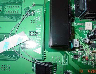
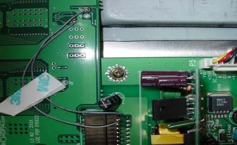
2 P6 cause : bad connection between Y-Board # 1, 2 drive board Connector pin Rework should be done P4 Y-Driver Board Y-Board


 Don t")
3 P 6 P 4 amplified amplified : outside Leg : inside Leg P 6, P 4 both are the first pin, when wiring, it should be done as picture shown. (bend the wire to Y-Driver B/D not to Y-B/D. If not there can be noise) Don t be confused with Pin number Improved since Dec,2001.
4

5
6
7
8
9
10
11


12

13
14

15
16

17


18 1) X - Board COF Connector separation Lift up the right and left of X-BOARD CONNECTOR. Lift up X-BOARD CONNECTOR and separate COP CONNECTOR by pulling up. When you handle COF CONNECTOR, don t pressure. First release LOCK and separate. If COF CONNECTOR is damaged, you should replace MODULE ASS Y. So, be aware of this!! COF Connector Warning When you exchange X-Board, first you should separate COF Connector. Be careful to to handle it. it. COF Connector is is attached to to Module. When COF Connector is is broken, Module ASS Y must be be replaced a new one.


19 2) X - Board Connector separation Lift up each edge of left/right. Lifted condition Be careful to handle LOCK or it can be broken. When LOCK is broken, replace a new X-BOARD. Warning It s easy to separate it by releasing Connector Lock. Do not pressure or it can be hurt. When LOCK is hurt, replace a new X-BOARD


20 3) Y - Board COF Connector separation Pull the white LOCK as shown in arrow Pull the white LOCK as shown in arrow. Separate COF CONNECTOR by pulling in the left. Warning Be careful to handle LOCK and COF Connector. When LOCK part is damaged, you should replace a new Y-Board. In case of COF Connector, Module Assembly.


21 4) Z - Board COF Connector separation Separate the fixed Screw of Z-Board. Pull out Lock as shown in arrow. Warning Condition in Lock part is pulled Be careful not to tear COF Connector. If COF Connector is torn, replace a new Module Assembly COF Connector Pull COF Connector as shown in arrow. It s easy to separate COF on condition that Z-Board Screw is separated. In case Z-Board is assembled, it s really hard to separate.


22 5) Connector separation Guide Push LOCK and pull out PUSH PUSH PUSH PUSH PUSH PULL


23 6) Control Board & VSC Board Connector


24 7) Gas injection (Sealing up) condition Be sealed up after gas injection Be sealed up after gas injection Warning Be careful to handle the sealed-up part after gas injection. If it is broken, the gas escapes. So, replace the Module.
25 8) Power off in 2 ~ 3 minutes(protection) Power Power is is On On and and off off 2~3 2~3 minutes. (Protection) P301 P301 Connector Open Open Check. Check. OK X --Board Board Top Top Right Right Change. P302 P302 Connector Open Open Check Check OK X --Board Board Top Top Left Left Change. P303 P303 Connector Open Open Check Check OK X --Board Board Bottom Right Right Change. P304 P304 Connector Open Open Check Check OK X --Board Board Bottom Left Left Change. P102 P102 Connector Open Open Check Check OK Z --Board Board Change. P3, P3, P2 P2 Connector Open Open Check Check OK Y --Board Board Change. P005, P005, P003 P003 Connector Open Open Check Check OK VSC- VSC-Board Change. PROTECT operation; When the load voltage is short. P006 P006 Connector Open Open Check Check OK VSC VSC --Board Board Change. Sound Sound Output Output IC IC Short Short Check Check When each voltage doesn t work (in general) Power Power Board Board Change
 Cause : No VS voltage L813 Coil cold soldering. Check Check Open the Connector connecting to each Board to check the power is off.")
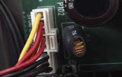
26 9) Power off in 2 ~ 3 minutes(protection) L813 Cold Solder Symptom : As soon as the power on, it s off in 2-3minutes. (PROTECT operation) Cause : No VS voltage L813 Coil cold soldering. Check Check Open the Connector connecting to each Board to check the power is off. if each Board is same, check the Power Board and voltage.
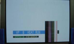
27 10) ADD BAR inspection and repair Press the ADJ KEY and check the position of add bar by changing WHITE or RED or BLUE or GREEN HEATRUN : WHITE Top Right Bottom Right Top Left Bottom Left MP-40PA10 uses 4 board such as left,right, top and bottom. Divide the screen in 4 and once you see ADD BAR check COF CONNECTOR between MODULE and X-BOARD. If there is no defect in COF CONNECTOR replace X-BOARD. But the problem still remains and check the connector between X-BOARD and CONTROL BOARD. And if you can t find defect, check CONTROL.


28 11) One Point Service Guide Symptom : B color 1 Address line Open Cause : Dented COF COF is dented


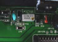
29 Symptom : Inferior R Address color Cause : Inferior DATA output by cold soldering 16 pin of IC14 in X-L-TOP ( Normal waveform after tearing off IC Pin) Countermeasure : Replace X-L-TOP board. IC14 Cold Soldering Abnormal waveform by cold soldering Normal waveform after tearing off IC pin
 and power off in 2 ~ 3 seconds. If you turn on again, it will be same problem.")
30 Symptom Causes Countermeasure If 15V line voltage reduces below 14V, Mis-discharge occurs and power off because of protection circuit. Replace PSU (Power Supply Unit) and defective X-Board. Defective X-Board The blue spreads on the screen (Mis-discharge) and power off in 2 ~ 3 seconds. If you turn on again, it will be same problem. Check Check If when Power on, screen shows like above and turn off in 2 seconds, check if turning off or not by disconnecting all X & Y boards.
 Check Check Check Top right X-BOARD 5V.")
31 Symptom Cause Countermeasure No 5V supply to Top right X-Board. Connect 5V line The top left part of screen is broken (Top Right X-BOARD) Check Check Check Top right X-BOARD 5V.(If 0V, it happens) Check 5V line from SMPS to X-BOARD.
 Check Check Check Top right X-BOARD Va(70V).")
32 Symptom Cause Countermeasure No Va(70V) supply to Top right X-Board. Connect 70V line Pinkish screen in the top left. (Top right X-BOARD) Check Check Check Top right X-BOARD Va(70V).(If 0V, it happens) Check 70V(Va) line from SMPS to X-BOARD.
 supply to Top right X-Board.")
 Check Check Check Top right X-BOARD 12V.")
33 Symptom Cause Countermeasure No 12V supply to Top right X-Board. No Va(70V) supply to Top right X-Board. Connect 12V line Connect 70V line The 3/5 top left in the screen is blank (Top Right X-BOARD) Check Check Check Top right X-BOARD 12V.( If 0V, it happens ) Check Top right X-BOARD Va(70V).(If 0V, it happens) Check 12V & 70V(Va) line from SMPS to X-BOARD.
 Check Check Check Top left X-BOARD 12V.( If 0V, it happens ) Check Top left X-BOARD Va(70V).(If 0V, it happens) Check 12V & Va(70V) line from SMPS to X-BOARD.")
34 Symptom Cause Countermeasure No 12V supply to Top left X-Board. No Va(70V) supply to Top left X-Board. Connect 12V line Connect 70V line The 3/5 top right of the screen is blank. (Top left X-BOARD) Check Check Check Top left X-BOARD 12V.( If 0V, it happens ) Check Top left X-BOARD Va(70V).(If 0V, it happens) Check 12V & Va(70V) line from SMPS to X-BOARD.

 Check Check Check the contact point and")
35 Symptom Cause Countermeasure P1 COF connector on Top left X-Board is open. Reassemble it Pinkish screen in the 1/5 top right (Top left X-BOARD) Check Check Check the contact point and Locking of P1 on Top left X-BOARD.
 Check Check Check Bottom right X-BOARD 5V.( If 0V, it happens ) Check 5V line from SMPS to X-BOARD.")
36 Symptom Cause Countermeasure No 5V supply to bottom right X-Board. Connect 5V line The 3/5 bottom left of screen is broken. (BOTTOM RIGHT X-BOARD) Check Check Check Bottom right X-BOARD 5V.( If 0V, it happens ) Check 5V line from SMPS to X-BOARD.
 Check Check Check Bottom right X-BOARD 12V.")
37 Symptom Cause Countermeasure No 12V supply to bottom right X-Board. Connect 12V line No Va(70V) supply to bottom right X-Board. The 3/5 bottom left of the screen is Blank. (Bottom Right X-BOARD) Check Check Check Bottom right X-BOARD 12V.( If 0V, it happens ) Check 12V line from SMPS to X-BOARD.
 Check Check Check Bottom left X-BOARD 5V.( If 0V, it happens ) Check 5V line from SMPS to X-BOARD.")
38 Symptom Cause Countermeasure No 5V supply to bottom left X-Board. Connect 5V line The 2/5 right of the screen is broken. (Bottom left X-BOARD) Check Check Check Bottom left X-BOARD 5V.( If 0V, it happens ) Check 5V line from SMPS to X-BOARD.
 Check Check Check Bottom left X-BOARD 12V.")
39 Symptom Cause Countermeasure No 12V supply to bottom left X-Board. Connect 12V line The 2/5 right part of the screen is blank. (Bottom left X-BOARD ) Check Check Check Bottom left X-BOARD 12V.( If 0V, it happens ) Check 12V line from SMPS to X-BOARD.

 Check Check Check connecting of the connector of")
40 Symptom Cause Countermeasure The connecting of X-Board bottom left connector is bad. Reassemble it. ADDRESS bar appears in the right bottom of the screen. (X-BOARD BOTTOM LEFT) Check Check Check connecting of the connector of bottom left X-BOARD. Reassemble it. X-BOARD BOTTOM LEFT CONNECTOR OPEN.

41


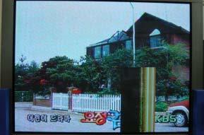
42 Symptom Cause Countermeasure Connector(P13) is OPEN or Connecting condition is bad Reassemble P13. Screen is divided in top and bottom, and vertical bar appears. Check Check P13 CONNECTOR contact point inferior CHECK. P13 CONNECTOR SIGNAL CHEK. P13 CONNECTOR

43 Symptom Cause Countermeasure VSC Board Connector is Open. Reassemble VSC Board Connector Screen is broken and has the vertical/horizontal bar. Check Check Check the connector connecting Reassemble the Connector
 Check Check Check the connection condition of the Connector.")
44 Symptom Cause Countermeasure Loose VSC Board Connector Reassemble VSC BOARD Connector The screen is bluish(mosaic screen) Check Check Check the connection condition of the Connector. Reassemble the Connector.


45 Symptom Cause Countermeasure Bad IC203 Replace IC203(VPC3230D) The mosaic appears in the screen when it connects to VIDEO Input. (The sensibility of Y-signal is low.) When connected to Component Input, it is O.K. Check Check Check if X201 on VSC board oscillates. Check Video In/Out of IC203 on VSC board. IC201 (VPC3230D) Decoder IC


46 IC201(VPC3230D) Decoder is inferior


47 Symptom Cause Countermeasure Bad Connector connecting Control Board and VSC B/D. Change the Connector Abnormal Normal Noise with division of colors Check Check Contact point and signal condition of Connector Control Board and VSC Board. Bad Connector
 * Heated : 1.5V Output(Normal Pin = 2.7V ) Bad IC2 (DA1) 2.")
48 Name No signal Vertical Bar Symptom Cause and Countermeasure 1.Cause : Bad IC2 (DA1) IC2 DA1(Data Arrange) No.162 Pin output is changing depending on the temperature. abnormal X-B d Buffer IC * Room temperature : 2.5V Output (Normal Pin = over 2.8V) * Heated : 1.5V Output(Normal Pin = 2.7V ) Bad IC2 (DA1) 2. Countermeasure : Replace IC2 < Waveform of normal pin> heated < Waveform of abnormal pin > heated 8cm DA1 DA1 Realization Buffer Buffer When ASIC Chip(IC2 DA1 LGD4001) on Control Board gets high temperature, you can observe it (In normal temperature it s O.K. ) Buffer(74ACT541) waveform abnormally narrows. In this case, it is impossible for Flip Flop(74AC574) on X B/D to read data.


49 Name Add Open (Green 1 Line) Symptom Cause and Countermeasure 1.cause: Add. COF Drive IC inferior Add. COF Drive IC Normal Line Data waveform Open Line Data output waveform the output of inferior line less than that of the normal Line Add. COF Drive IC inferior COF inspection : 24V Open check (normal 50V)
 -.R14,17,18,21 : 330 ==> 4.7K (Chip Resistor) -.")
 2. Remove Power Cord (Power s off) 3.")
50 Name Vertical bar when Power off/on(mis-discharge) Symptom Cause and Countermeasure 1.Cause : Control board malfunctions when Power off/on. 2.Countermeasure: Change some parts on Control board. 3.Changing parts : A32_CTRL_03 B/D (Marked on PCB) -.R14,17,18,21 : 330 ==> 4.7K (Chip Resistor) -.R15,16,19,20 : 22K ==> 4.7K (Chip Resistor) -.C504, 505 : 0.1uF / 50V add (Chip Capacitor) Control board Realization 1.PDP Power on Mode external input (regardless of wire/wireless signal but it s easy to reenact in wireless signal) 2. Remove Power Cord (Power s off) 3.after about 20minutes, insert Power cord (automatically the Power s on and the vertical bar is shown as above)
51 <SMPS Board> TP5 GND When replacing PDP module & power board, Be sure to adjust Power Ass y voltage. VA Adjust VR8401 TP6 VA VS Adjust VR8501 TP3 GND TP4 VS ++ DMM PFC + PFC - 380V 1V VR801 PFC PACK 1. PFC adjustment -. Select 100% White Pattern signal and warm it up enough. -. Connect DMM with TP PFC+ and TP PFC (GND). -. adjust VR801 to 380V (within 1V ). 2. Va adjustment -. Connect DMM + terminal with P814 #1 Pin. -. Turn VR8401 (Va Adj) to adjust the voltage on DMM to Va voltage value marked on panel bottom- right label. (allowable error : 0.5V ) 3. Vs adjustment -. Connect DMM s + terminal with P803 # 9 Pin. -. Turn VR 8501 (Vs Adj )to adjust the voltage on DMM to Vs voltage value marked on panel bottom-right label.
52 Power & no Raster AC input check (220V) Connection Plug with set When Main S/W ON, ST-BY LED ON check (RED) AC Line Fuse check When SUB S/W on, LED GREEN check PFC Board R8301,R8302 R8303 OPEN check R8301,R8302,R8303 replacement R8538, R8539,R8540 OPEN check FAN function check 5V MONI, 5V CTL output check VS, VA PACK Function check Controller Board VS ON check Controller Board replacement each Connector & connection check
53 Connector between SP & set check IC601 (MSP3401) check IC603 (LA4282) check Input jack check (25Pin cable L,R input check) Sound power (P806A,B) Cable connection check Sound terminal Voltage check (32V) F8811 Fuse Open check Speaker connection line check
54 Abnormal screen PC signal input IC501 ( JAGASM check ) IC203 ( CXA2101 ) check IC901 (SII 150 ) check) IC406 ( ADV 7123 ) check P901 ( 21 Pin cable ) check IC404 ( FLI2220 ) check IC403 ( FLI2220 )check IC201 (VPC3230 ) check Input jack & Connector check
 check F8301 Fuse (15A) replacement F8302 Fuse")
55 AC power voltage check Main Power S/W check F8301 Fuse (15A) check F8301 Fuse (15A) replacement F8302 Fuse check

56 Disappearing or error while watching
 X -")
57 Automatic off as soon as power is on ( Protect ) X - Board
 Y -")
58 Automatic off as soon as power is on ( Protect ) Y - Board

")
59 X-Board Connector check X-Board replacement Module ( Panel )replacement

")
60 X-Board Connector check X-Board replacement Module ( Panel )replacement
61 Y-Drive Board ( Top ) Drive IC check Y-Drive Board replacement
62 Y-Drive Board ( Bottom ) Drive IC check Y-Drive Board replacement

63 Y-Drive Board ( Top ) Drive IC check Y-Drive Board replacement
64 VSC Board & Controller Board Connector check Controller Board check Controller Board replacement
65 Address Bar ( Vertical ) & partial no-picture Central top 4/10 of the screen with vertical bar related X-Board power supply voltage check Central top 4/10 of screen with no-picture related X-Board Connector check related X-Board & Controller Board Connector check related X-Board replacement Module (Panel ) check
66 Address Bar ( Vertical ) & partial no-picture Bottom left 3/10 of the screen with vertical bar Related X-Board power supply voltage check Bottom left 3/10 of the screen with no-picture Related X-Board Connector check Related X-Board & Controller Board Connector check Related X-Board replacement Module (Panel ) check
67 Address Bar ( Vertical ) & partial no-picture Bottom right 3/10 of the screen with vertical bar Bottom right 3/10 of the screen with no-picture related X-Board power supply voltage check Related X-Board Connector check Related X-Board & Controller Board Connector check Related X-Board replacement Module (Panel ) check
68 Address Bar ( Vertical ) & partial no-picture Central bottom 4/10 of the screen with vertical bar Related X-Board power supply voltage check Central bottom 4/10 of the screen with no-picture Related X-Board Connector check Related X-Board & Controller Board Connector check Related X-Board replacement Module (Panel ) check
69 Address Bar ( Vertical ) & partial no-picture Related X-Board power supply voltage check Related X-Board Connector check Related X-Board & Controller Board Connector check Related X-Board replacement Module (Panel ) check
70 Address Bar ( Vertical ) & partial no-picture Related X-Board power supply voltage check Related X-Board Connector check Related X-Board & Controller Board Connector check Related X-Board replacement Module (Panel ) check
Plasma Panel Replacement Guide DU-42PX12X
 Plasma Panel Replacement Guide DU-42PX12X Panel Replacement: At this point, the panel has been determined to be defective and replacement is necessary. Upon receiving the replacement panel, it must be
Installation instructions DC Protection and Delay unit, Version 1.2 The package should contain: A piece of normal gauge yellow wire for the AC connect
 Installation instructions DC Protection and Delay unit, Version 1.2 How does the unit work? Delay: Basically a capacitor is charged via a resistor, when the voltage of the capacitor reach a certain level,
4.8. Other Errors Image system problem
 4.8. Other Errors 4.8.1. Image system problem No Problem Description Troubleshooting Page 1 Toner cartridge detection error P.4 242 2 Image registration problem occurs after ACR (Auto Color Registration)
Technical Guide Plasma (GPH10DU Chassis) Troubleshooting Handbook
 Troubleshooting Handbook") Technical Guide Plasma (GPH10DU Chassis) Troubleshooting Handbook Model : TH-42PX75U TH-50PX75U TH-42PX77U TH-50PX77U Panasonic Services Company National Training Prepared by Panasonic Service and Technology
Technical Guide Plasma (GPH10DU Chassis) Troubleshooting Handbook Model : TH-42PX75U TH-50PX75U TH-42PX77U TH-50PX77U Panasonic Services Company National Training Prepared by Panasonic Service and Technology
PANDORA HACKER GUIDE
 PANDORA HACKER GUIDE WARNING: Modifying your PCB is not covered by your warranty and any damage caused as a result will be the sole responsibility of the owner to fix or to have fixed at a fee set by the
9 th Generation Plasma Display. Technical Information
 9 th Generation Plasma Display Technical Information 1 The technicians have express their needs and we listened. This presentation has been developed especially for the technicians involved in the repair
2005 Pioneer Home Audio Seminar VSX49TX
 2005 Pioneer Home Audio Seminar VSX49TX Pioneer Electronic Service, Inc. 2005 Introduction Why the VSX49TX? The VSX49TX is not current product, however it tends to be the most difficult to repair! What
Onwards and Upwards, Your near space guide Overview of the NearSys Two Sensor Temperature Array Figure 1. A complete Two Sensor Temperature Array
 The NearSys Two Sensor Temperature Array is a kit that permits a BalloonSat to measure two separate temperatures. When plugged into a flight computer like the BalloonSat Mini, the flight computer provides
Phase Loss Protection Upgrade. Phase Loss Protection Upgrade. In this bulletin:
 Phase Loss Protection Upgrade In this bulletin: Introduction... 2 Purpose... 2 General... 2 Applicability... 2 HD3070 Phase Loss Protection Upgrade Kit Parts... 2 Preparation... 4 Install the Phase Loss
midi LOGGER 200 SERVICE MANUAL GL200-UM-251 GL200-UM
 midi LOGGER 200 GL200-UM-251 SERVICE MANUAL GL200-UM-251-03-9370 HISTORY OF REVISIONS No. Date issued Description of revision Page Edition 1 06.02.14 First Printing All 01 2 06.03.29 Information for the
********SERVICE MANUAL******** MODELS:
 ********SERVICE MANUAL******** MODELS: 75211-10 Variable Speed Drive, 5000 RPM, 115 V 75211-15 Variable Speed Drive, 5000 RPM, 230 V, CE Mark 75211-60 Variable Speed Drive w/pump, 9000 RPM, 115 V 75211-62
V-9939C MICROPHONE ADAPTER
 Issue 2 INTRODUCTION These instructions provide identification, installation, connection, operation and maintenance information for the Microphone Adapter. The is a Microphone Adapter designed to be used
DLA. DMX512 Analyzer. DLA Users Manual SV2_00 B.lwp copyright ELM Video Technology, Inc.
 DLA DMX512 Analyzer DLA DLA-HH 1 Table Of Contents IMPORTANT SAFEGUARDS... 2 DLA OVERVIEW... 3 CONNECTION... 3 OPERATION... 3 HARDWARE SETUP... 4 DLA-HH (PORTABLE) LAYOUT... 4 CHASSIS LAYOUT... 4 DLA MENU
Schematic Diagram: R2,R3,R4,R7 are ¼ Watt; R5,R6 are 220 Ohm ½ Watt (or two 470 Ohm ¼ Watt in parallel)
") Nano DDS VFO Rev_2 Assembly Manual Farrukh Zia, K2ZIA, 2016_0130 Featured in ARRL QST March 2016 Issue Nano DDS VFO is a modification of the original VFO design in Arduino Projects for Amateur Radio by
Nano DDS VFO Rev_2 Assembly Manual Farrukh Zia, K2ZIA, 2016_0130 Featured in ARRL QST March 2016 Issue Nano DDS VFO is a modification of the original VFO design in Arduino Projects for Amateur Radio by
solutions for teaching and learning
 RKAmp1 Component List and Instructions PCB layout Constructed PCB Schematic RKAmp1 Stereo Amplifier Page 1 Description The RKAmp1 stereo amplifier PCB has been designed around the 2 x 1watt stereo amplifier
Figure 1. A complete Temperature Sensor
 The NearSys Temperature Sensor is a kit that permits a BalloonSat to measure the temperature of the air, interior, or object the sensor itself is placed in contact with. When plugged into a flight computer
Colecovision 5v Memory Mod Installation
 Colecovision 5v Memory Mod Installation The Colecovision suffers from common failure points: the power supply, power switch, and 4116 DRAM. The power supply suffers from poor soldering, the power switch
VG-305A AC Traffic Light Controller Kit
 Galak Electronics Electronic kits and components Website: GalakElectronics.com Email: sales@galakelectronics.com Phone: (302) 832-1978 VG-305A AC Traffic Light Controller Kit Thank you for your purchase
DDS Unit Construction Guide of TJ6A pro
 DDS Unit Construction Guide of TJ6A pro The main board, PA and the DDS function of TJ6A pro is the same with TJ6A. The different part is the DDS unit in which the S meter unit (SM unit) is add (see picture
Insert the male, 90 angled, 2x10 connectors into the corresponding 2x10 sockets and put them in place, flat under the PCB. Solder.
 MC624 Assembly guide Safety warning The kits are main powered and use potentially lethal voltages. Under no circumstance should someone undertake the realisation of a kit unless he has full knowledge about
HP Pavilion dv7-6c90us Cooling fan Replacement
 HP Pavilion dv7-6c90us Cooling fan Replacement This guide will walk you through the process of replacing the cooling fan in an HP Pavilion dv7 laptop. Written By: Angelina Clayton ifixit CC BY-NC-SA www.ifixit.com
Touch Control Switch + - R6 R4 R8 R7 CAT# Grading. Assembly Instructions by Earl D. Gates SUNY Oswego Fall Conference 2007.
 Grading Name: Class: Shade the number in column A that reflects your ability. In column B, have your instructor do the same. 6. Ability to identify and use basic electronic assembly tools. 8. Ability to
Pacific Antenna Two Tone Generator
 Pacific Antenna Two Tone Generator Description Our Two Tone Generator kit provides two non-harmonic, sine wave signals for testing audio circuits Outputs of approximately 700Hz and 1900Hz and the combination
Assembling The Shutterbug Remote DIY Kit
 Assembling The Shutterbug Remote DIY Kit Required Tools and Setup To assemble your Shutterbug Remote, you ll need a soldering iron, flux core solder, and tweezers. Solder braid and flux are also recommended
The GENIE Light Kit is ideal for introducing simple lighting projects, such as an electronic die, a wearable badge or a night-time warning system.
 Introduction 1 Welcome to the GENIE microcontroller system! The GENIE Light Kit is ideal for introducing simple lighting projects, such as an electronic die, a wearable badge or a night-time warning system.
Transcendent Frequency Counter
 Transcendent Frequency Counter with blue 2 x 16 LCD display This manual will guide you how to assemble, test and operate this frequency counter KIT. Features: The transcendent counter has two input channels
BIPOLAR PROM ADAPTER READ THIS SHEET FIRST!
 BIPOLAR PROM ADAPTER READ THIS SHEET FIRST! The BIPOLAR PROM ADAPTER (#ABIP) must be used with caution. The addendum which accompanies the adapter describes the precautions which must be followed for the
X/Y Issues on ASP-645-1
 X/Y Issues on ASP-645-1 Issues seen with X or Y problems: A) Table will not move in X or Y when you are using the Frame Arrow buttons on the control panel. B) On power up the control panel gives Error
Soartronic IOIO UART interface v2e assembly manual.
 Soartronic IOIO UART interface v2e assembly manual www.soartronic.com 1 This manual is for both IOIO v1 and IOIO-OTG Components assembled should look like this: components marked with RED arrows have polarity,
Operating Instructions & Service Manual FOULS
 FOULS Operating Instructions & Service Manual FOULS Basketball Player Fouls Panels Model MP-5215 EFFECTIVE S.N. 17,100, June 18, 2001 TABLE OF CONTENTS PAGE 1. GENERAL INFORMATION 3 1.1 DESCRIPTION 1.2
MP3 audio amplifier. Build Instructions. Issue 2.0
 MP3 audio amplifier Build Instructions Issue 2.0 Build Instructions Before you put any components in the board or pick up the soldering iron, just take a look at the Printed Circuit Board (PCB). The components
V-9939B MICROPHONE ADAPTER
 Issue 10 INTRODUCTION These instructions provide identification, installation, connection, operation and maintenance information for the Microphone Adapter. The is a Microphone Adapter designed to be used
Installation/assembly manual for DCC/Power shield
 Installation/assembly manual for DCC/Power shield The DCC circuit consists of the following components: R1/R6 R2/R3 R4/R5 D1 C2 2 kω resistor ½ Watt (colour code Red/Black/Black/Brown/Brown) 10 kω resistor
PowerAmp Design. PowerAmp Design EVAL127 EVALUATION KIT FOR PAD127/157. Rev G
 PowerAmp Design EVALUATION KIT FOR PAD7/57 EVAL7 Rev G INTRODUCTION The EVAL7 assembled evaluation kit provides a convenient method to become familiar with the operation of the PAD7/57 operational amplifiers
K1EL Morse Code Practice Oscillator CPO
 Features This is an oscillator not a Morse keyer Input source can be a keyer or straight key Near Sine wave tone output CPO Tone Volume Control CPO Tone Frequency Control Use headphones or external speaker
Blue Point Engineering
 Blue Point Engineering Board - Pro Module (E) Instruction Pointing the Way to Solutions! Controller I Version 2.1 The Board Pro E Module provides the following features: Up to 4 minutes recording time
LGE PDP 2K6. Colour Television PDP42X3*
 Colour Television Module LGE PDP K6 PDP4X3* Contents Page. Technical Specifications, Connections, and Chassis Overview. Safety Instructions, Warnings, and Notes 5 3. Directions for Use 6 4. Mechanical
L-80 SERIES HOME & COMMERCIAL HIGH-TECH ENTERTAINMENT CENTER DIAGNOSTIC ADDENDUM
 111 Canfield Avenue Randolph, New Jersey 07869 1-800-LANDICE FAX 973-927-0630 L-80 SERIES HOME & COMMERCIAL HIGH-TECH ENTERTAINMENT CENTER DIAGSTIC ADDENDUM High-Tech Entertainment Center Explosion Part
Post Tenebras Lab. Written By: Post Tenebras Lab
 Post Tenebras Lab PTL-ino is an Arduino comptaible board, made entirely out of through-hole components. It is a perfect project to learn how to solder and start getting into the world of micro controllers.
EE 354 August 1, 2017 Assembly of the AT89C51CC03 board
 EE 354 August 1, 2017 Assembly of the AT89C51CC03 board The AT89C51CC03 board comes as a kit which you must put together. The kit has the following parts: No. ID Description 1 1.5" x 3.25" printed circuit
Morse Code Practice Oscillator
 Features Description Keyer speed range: Limited only by keying source True Sine wave tone output Tone Volume Control Tone Frequency Control Internal Speaker 1/8 External Speaker/Headphone Jack RCA Key
Construction Construction Instructions
 Semi-Virtual Diskette SVD Construction Construction Instructions PCB version 2.0 September 2004 Eric J. Rothfus Table of Contents Table of Contents... i Parts List...1 Construction Overview...5 PCB Construction...
SP-100. Service Manual Aug. 02
 SP-100 Service 2004. Aug. 02 1. Caution for maintenance and Service. Please take care below points when you do Service and Maintenance. (1) Service and Maintenance should be done under safety condition.
COLOR VIDEO DOOR PHONE
 www.commax.in.ua COLOR VIDEO DOOR PHONE.in.ua Model No. CDV-72BE a513-11, Sangdaewon-dong, Jungwon-gu, Seongnam-si, Gyeonggi-do, Korea Int l Business Dept. Tel.; : +82-31-7393-540~550 Fax.; +82-31-745-2133
AUDIO AMPLIFIER PROJECT
 Intro to Electronics 110 - Audio Amplifier Project AUDIO AMPLIFIER PROJECT In this project, you will learn how to master a device by studying all the parts and building it with a partner. Our test subject:
K8099 NIXIE CLOCK. * optional enclosure TKOK19 (black) - TKOK17 (white) ** optional plexiglass enlcosure B8099 ILLUSTRATED ASSEMBLY MANUAL
 - TKOK17 (white) ** optional plexiglass enlcosure B8099 ILLUSTRATED ASSEMBLY MANUAL") Total solder points: 230 + 74 Difficulty level: beginner 1 2 3 4 5 advanced NIXIE CLOCK K8099 ** * A unique combination of both vintage and modern electronics ILLUSTRATED ASSEMBLY MANUAL H8099IP-1 * optional
Total solder points: 230 + 74 Difficulty level: beginner 1 2 3 4 5 advanced NIXIE CLOCK K8099 ** * A unique combination of both vintage and modern electronics ILLUSTRATED ASSEMBLY MANUAL H8099IP-1 * optional
CP 64 BD15 CP 64 PD15
 COLOR PAR 64 CP 64 BD15 CP 64 PD15 User Manual Please read the instruction carefully before use Contents 1. Safety Instruction...2 2. Technical Specification...3 3. Installation...4 4. DMX Address Setting...4
E2460GS Oscilloscope Upgrade Kit
 Installation Instructions for E2460GS Oscilloscope Upgrade Kit Agilent 1670G-Series Logic Analyzers This kit upgrades either the Agilent Technologies 1670G, Agilent 1671G, Agilent 1672G, or the Agilent
PARTS CATALOGUE / TECHNICAL GUIDE Cal. S149A
 PARTS CATALOGUE / TECHNICAL GUIDE [SPECIFICATIONS] Item Module Cal. No. S149A (x 0.30) Module size Outside diameter 198.1 mm between 6 o clock and 12 o clock sides 81.6 mm between 3 o clock and 9 o clock
Sony SLT Alpha-65V Flash Capacitor
 Sony SLT Alpha-65V Flash Capacitor Replacement How to replace the flash capacitor located on the left side of the camera. Written By: Dima Kyle ifixit CC BY-NC-SA www.ifixit.com Page 1 of 11 INTRODUCTION
Troubleshooting CHAPTER
 CHAPTER 1 1 1 1 0 1 1 0 1 1 0 1 1 0 1 1 0 1 1 0 1 1 0 1 1 1 0 1 6 0 1 1 0 1 1 0 1 0 1 10 1 0 1 1 0 1 0 1 1 0 1 0 1 1 0 1 10 Troubleshooting NOTICE: Information in this manual may change without notice.
Vector Drive - Troubleshooting Guide
 Haas Technical Documentation Vector Drive - Troubleshooting Guide Scan code to get the latest version of this document Translation Available The Haas Vector drive is the source of power for the spindle
STAGE TRI-PAR 18TC CP-18TC. User Manual. Please read the instructions carefully before use
 STAGE TRI-PAR 18TC CP-18TC User Manual Please read the instructions carefully before use TABLE OF CONTENTS 1. Safety Instructions 2. Technical Specifications 3. How to Set the Fixture 4. How to Control
RECORD & PLAYBACK KIT
 ESSENTIAL INFORMATION BUILD INSTRUCTIONS CHECKING YOUR PCB & FAULT-FINDING MECHANICAL DETAILS HOW THE KIT WORKS ADD AN AUDIO MESSAGE TO YOUR PRODUCT WITH THIS RECORD & PLAYBACK KIT Version 2.1 Build Instructions
Vector Drive - Troubleshooting Guide
 Haas Technical Documentation Vector Drive - Troubleshooting Guide Scan code to get the latest version of this document Translation Available The Haas Vector drive is the source of power for the spindle
IDEAL INDUSTRIES, INC. TECHNICAL MANUAL MODEL:
 IDEAL INDUSTRIES, INC. TECHNICAL MANUAL MODEL: 61-796 The Service Information provides the following information: Precautions and safety information Specifications Performance test procedure Calibration
Snail Gear Building instructions V1.0
 Snail Gear Building instructions V1.0 Table of contents Components... 3 PCB layout... 4 General guideline for components... 5 General building tips... 5 Modifications... 6 Biasing... 7 Off board wiring...
Pololu 12V Step-Up/Step-Down Voltage Regulator S10V2F12
 Pololu 12V Step-Up/Step-Down Voltage Regulator S10V2F12 Overview The Pololu step-up/step-down voltage regulator S10V2F12 is a switching regulator (also called a switched-mode power supply (SMPS) or DC-to-DC
10W LED PIN SPOT. User Manual LED-PS10D W. Innovation, Quality, Performance. Professional Entertainment Technology 11-
 Innovation, Quality, Performance 11-10W LED PIN SPOT LED-PS10D W User Manual Professional Entertainment Technology TABLE OF CONTENTS 1. Safety Instruction 2. Technical Specification 3. Installation 4.
AT&T. ZoneMate 3 Service Manual. PagePac 20 Voice Paging System. MERLIN CS Connection And Operation
 AT&T PagePac 20 Voice Paging System ZoneMate 3 Service Manual MERLIN CS Connection And Operation ZoneMate 3 Service Manual For PagePac 20 Voice Paging System and Merlin* Communications System Models 1030
Shack Clock kit. U3S Rev 2 PCB 1. Introduction
 Shack Clock kit U3S Rev 2 PCB 1. Introduction Thank you for purchasing the QRP Labs Shack Clock kit. This clock uses the Ultimate3S QRSS/WSPR kit hardware, but a different firmware version. It can be used
PlayStation 3 Teardown PS3. Written By: Mint137. ifixit CC BY-NC-SA Page 1 of 22
 PlayStation 3 Teardown PS3 Written By: Mint137 ifixit CC BY-NC-SA www.ifixit.com Page 1 of 22 INTRODUCTION This is a teardown of an original launch 60GB PlayStation 3 system. One of the best units out
BehringerMods.com. Instructions for modification of Behringer SRC analog inputs and outputs
 BehringerMods.com Instructions for modification of Behringer SRC analog inputs and outputs The following instructions will cover the details of fully modifying a unit with analog output and analog input
revolution How does the ibutton work? Full kit including PCB, PICAXE-08M chip and ibutton key. Spare ibutton Key
 AXE109S LOG020 Full kit including PCB, PICAXE-08M chip and ibutton key. Spare ibutton Key The ibutton is an electronic chip armoured in a 16mm stainless steel can. Because of this unique, durable package,
RPX Series USER S MANUAL
 RPX Series USER S MANUAL INDEX 1.1 Introduction page 1 1.2 Packing page 1 1.3 Drawing page 2~16 1.4 Features page 17 1.5 Specification page 18~21 1.6 Installation & Testing page 22~23 1.7 Hot-Swap Procedures
BuffaloLabs WiFi Lantern Assembly guide version 1
 BuffaloLabs WiFi Lantern Assembly guide version 1 Needed equipment: Solder iron Solder wire Cutter Wire stripper (optional) Hot glue gun Overview of the components (not including USB cable and box panels)
Uzebox Kit Assembly Guide
 Uzebox Kit Assembly Guide V1.3 Page 1 of 18 Revision History Version Date Author Description 1.0 01-Nov-2012 A.Bourque Initial release 1.1 6-Nov-2012 A.Bourque Minor corrections 1.2 28-Jan-2014 A.Bourque
TD-700 FLUOROMETER SERVICE MANUAL
 TD-700 FLUOROMETER SERVICE MANUAL July 1996 CONTENTS Page Section 1 INTRODUCTION 2 Section 2 PRELIMINARY CHECKS 3 Section 3 TROUBLESHOOTING GUIDE 5 A. Lamp (Fluorescent) 5 B. Lamp Heater 7 C. Fan 8 D.
EPS Power Supply
 EPS - 600 Power Supply Installation and Operation Manual Version 1.0 *This instrument is intended for laboratory use only Index A. Important Notice ----------------------------------------------------------------
Lab 3: Building a Power Supply and a Stereo Amplifier
 ECE 212 Spring 2010 Circuit Analysis II Names: Objectives Lab 3: Building a Power Supply and a Stereo Amplifier In this lab exercise you will build a regulated variable-voltage power supply and a 10-watt
LIFI LCD Projection TV Service Training Guide
 LIFI LCD Projection TV Service Training Guide LIFI series LIFI = LIght FIdelity Contents: Service Policy Board Access No Start Up Shutdown Service Mode Adjustments 720p PT-50LCX7 PT-56LCX7, 70 PT-56LCX7,
Creep Cluster Build Document. V5 - November 2018
 Creep Cluster Build Document. V5 - November 2018 Dual triangle oscillators are hard-switched by a fast squarewave. Then the signal goes into a resonant lowpass filter. Sounds vary from deep rumbling drones
2015 SIMMCONN LABS, LLC. All rights reserved. NewScope-T1 Operation Manual
 2015 SIMMCONN LABS, LLC. All rights reserved NewScope-T1 Operation Manual April 12, 2017 NewScope-T1 Operation Manual 1 Introduction... 3 2 Installation... 4 2.1 Initial Inspection... 4 2.2 Installation
MFA-0801 & MFA-1201 D-M-E Smart Series Low Voltage Temperature Control System. User s Manual. D-M-E Company
 MFA-0801 & MFA-1201 D-M-E Smart Series Low Voltage Temperature Control System User s Manual D-M-E Company D-M-E Company MFA-0801 & MFA-1201 Page 1 Copyright D-M-E Company 1995. All rights reserved. D-M-E
LED PANEL. User Manual Please read the instructions carefully before use LED-212RGB TABLE OF CONTENTS. 1. Safety Instructions
 TABLE OF CONTENTS LED PANEL 1. Safety Instructions 2. Technical Specifications 3. Installation 4. How to set the unit 5. How to control the fixture 6. DMX512 Configuration 7. DMX512 Connections 8. Troubleshooting
midi LOGGER 220 GL220-UM-251
 midi LOGGER 220 GL220-UM-251 SERVICE MANUAL GL220-UM-251-03-9370 HISTORY OF REVISIONS No. Date issued Description of revision Page Edition 1 10.03.29 First Printing All 01 2 10.04.16 The size of screws
High Power (15W + 15W) Stereo Amplifier
 Stereo Amplifier") High Power (15W + 15W) Stereo Amplifier Build Instructions Issue 1.0 Build Instructions Before you put any components in the board or pick up the soldering iron, just take a look at the Printed Circuit
High Power (15W + 15W) Stereo Amplifier Build Instructions Issue 1.0 Build Instructions Before you put any components in the board or pick up the soldering iron, just take a look at the Printed Circuit
FIELD REPLACEABLE UNIT DOCUMENTATION. Portege R100 GENERAL INFORMATION. Tools Required for Proper Disassembly and Reassembly:
 Portege TM GENERAL INFORMATION Tools Required for Proper Disassembly and Reassembly: 1. Phillips Screwdriver (Size 0) 2. Flat head Screwdriver 3. Case Separator 4. ESD Wrist Strap 5. ESD mat 6. Tweezers
HOME THEATER PC CHASSIS
 HOME THEATER PC CHASSIS Model: HTPC 280 BAV4 & SAV4 Color: Black & Silver Quick Installation Guide (U.S. & Canada Only) Version 1.0 DISCLAIMER No warranty or representation, either expressed or implied,
DSI-4. DMX Optically Isolated 1x4 Splitter. D Series. DSI_4 Users Manual r3.lwp copyright 2009, 2010, 2011 ELM V. T. Inc.
 DSI-4 DMX Optically Isolated 1x4 Splitter D Series 1 Table Of Contents IMPORTANT SAFEGUARDS... DSI-4 OVERVIEW... CONNECTION... PCB BLOCK DIAGRAM... SERVICING... TROUBLESHOOTING... SPECIFICATIONS... 2 3
Effects Loop Installation Guide
 Warnings and Disclaimer Effects Loop Installation Guide You will be working with HIGH VOLTAGE. These voltages CAN BE DEADLY if you are not extremely careful. If you are not comfortable working with HIGH
SharpSky Focuser Construction. SharpSky Focuser. Construction Document V st December 2012 Dave Trewren 1
 SharpSky Focuser Construction Document V0.12 1st December 2012 Dave Trewren 1 Contents 1 General... 3 1.1 Change Record... 3 1.2 References... 3 2 Introduction... 5 3 SharpSky driver installation... 5
Installation Manual on Continuous ink supply system (CISS) For printer Canon IP 4000
 For printer Canon IP 4000") Installation Manual on Continuous ink supply system (CISS) For printer Canon IP 4000 Thank you for using the INKSYSTEM Continuous ink supply system. It is the best device for an inkjet printer, and it
Installation Manual on Continuous ink supply system (CISS) For printer Canon IP 4000 Thank you for using the INKSYSTEM Continuous ink supply system. It is the best device for an inkjet printer, and it
Darksoft s Sega ST-V Multicart
 Game selector for Darksoft s Sega ST-V Multicart Version 1.0 "1 Selector board Game selector board consists of Arduino Nano clone for the logic, two row LCD screen with buttons and main PCB with connectors
LED BEAM MOVING HEAD FL x3W User Manual
 LED BEAM MOVING HEAD FL-101 36x3W User Manual www.flash-butrym.pl Page 1 1. Preface 1.1 Packing list Product name moving head light Power -line User manual quantity 1 pcs 1 base 1 pcs 1.2 Unpacking instructions
Operation Manual. Concorde 600 Power Supply. *This instrument is intended for laboratory use only.
 Concorde 600 Power Supply Operation Manual Cat.no. R10-1001011 *This instrument is intended for laboratory use only http://www.recenttec.com E-mail : support@recenttec.com Version 1.1 Packing List x 1
Uzebox Kit Assembly Guide
 Uzebox Kit Assembly Guide V1.7 Page 1 of 21 Revision History Version Date Author Description 1.0 01-Nov-2012 A.Bourque Initial release 1.1 6-Nov-2012 A.Bourque Minor corrections 1.2 28-Jan-2014 A.Bourque
Nintendo DSi Touch Screen / Bottom LCD Replacement
 Nintendo DSi Touch Screen / Bottom LCD Replacement Disassembly and replacement of the lower LCD / touch screen Written By: bushing ifixit CC BY-NC-SA www.ifixit.com Page 1 of 15 INTRODUCTION This guide
V-9941A ONE ZONE HANDSFREE TALKBACK CONTROL UNIT
 VSP- Issue 4 ONE ZONE HANDSFREE TALKBACK CONTROL UNIT INTRODUCTION The is a One Zone Handsfree Page Unit for use on an Electronic Key system line key position, a PABX loop start trunk port, a dedicated
INDEX. Analog Board Boot and Voltage Test 2 Testing Input Channels 3 Testing Output Channels 4
 INDEX Analog Board Boot and Voltage Test 2 Testing Input Channels 3 Testing Output Channels 4 Digital Board Boot and Voltage Test 5 Testing Input Channels 6 Testing Output Channels 7 Display Testing 8
SAMURAI SCAN 50 LED-SC50D. User Guide. Innovation, Quality, Performance. Professional Entertainment Technology 19-
 SAMURAI SCAN 50 LED-SC50D Innovation, Quality, Performance User Guide Professional Entertainment Technology 19- EC Declaration of Conformity We declare that our products (lighting equipments) comply with
[Note: Power adapter is not included in the kits. Users need to prepare a 9 12 V ( >300mA capacity ) DC power supply]
![[Note: Power adapter is not included in the kits. Users need to prepare a 9 12 V ( >300mA capacity ) DC power supply]](/thumbs/76/74094055.jpg "[Note: Power adapter is not included in the kits. Users need to prepare a 9 12 V ( >300mA capacity ) DC power supply]") 062 LCD Oscilloscope Assembly Notes Applicable Models: 06203KP, 06204KP DN062-18v02 Important Notes 1. Some components shown in the schematic and PCB layout are for options or adjustments. They do not
062 LCD Oscilloscope Assembly Notes Applicable Models: 06203KP, 06204KP DN062-18v02 Important Notes 1. Some components shown in the schematic and PCB layout are for options or adjustments. They do not
EL7060 Series SERVICE MANUAL
 EL7060 Series SERVICE MANUAL 1 TABLE OF CONTENTS 1 General description... 4 1.1 Exploded view... 5 2 ACCESSIBILITY... 5 2.1 Dust Bag Cover.. 7 2.2 Display Cover.8 2.3 PCB Display/Switch..9 2.4 Top Cover..10
Chill Interface PCB Assembly Instructions
 ExcelValley Chill Interface PCB Waveblaster Module MIDI Interface Board Chill Limited Edition V2 Assembly Kit Standalone midi interface board for Waveblaster synthesizer modules. Suitable for most Waveblaster
midi LOGGER 820 GL820-UM-251
 midi LOGGER 820 GL820-UM-251 SERVICE MANUAL GL820-UM-251-02-9370 HISTORY OF REVISIONS No. Date issued Description of revision Page Edition 1 10.02.18 First Printing All 01 2 10.04.06 The size of screws
Adafruit MAX98357 I2S Class-D Mono Amp
 Adafruit MAX98357 I2S Class-D Mono Amp Created by lady ada Last updated on 2016-06-14 02:09:38 PM EDT Guide Contents Guide Contents Overview Pinouts Speaker Output Power Pins I2S Pins Other Pins Gain SD
MATRIX LED LED User Manual Please read the instructions carefully before use
 MATRIX LED LED-7871 User Manual Please read the instructions carefully before use 1- 1. Safety Introductions TABLE OF CONTENTS WARNING Please read the instructions carefully which includes important information
Freeze the Dizz Jameco Part No
 Freeze the Dizz Jameco Part No. 2161431 This project is based on a children s arcade game. Twenty LEDs are placed on a ring and each takes turn to light up forming a rotating light spot. If a push-button
OpenSprinkler v2.1u Build Instructions
 OpenSprinkler v2.1u Build Instructions (Note: all images below are 'clickable', in order for you to see the full-resolution details. ) Part 0: Parts Check Part 1: Soldering Part 2: Testing Part 3: Enclosure
Design Modular Planning
 Phys253 - Lecture 7, Part II Circuit Components & Layout Design Modular Planning Design by assembling simple circuit modules, such as filters or amplifiers Modules may be separated by buffers, where required