9 th Generation Plasma Display. Technical Information
|
|
|
- Holly Bennett
- 6 years ago
- Views:
Transcription

1 9 th Generation Plasma Display Technical Information 1
2 The technicians have express their needs and we listened. This presentation has been developed especially for the technicians involved in the repair of our plasma televisions. We ve gathered and analyzed your s, questions, feedback, and requests. Based on this information, we have put together a presentation to fulfill your needs. 2
3 Topics Power Supply/System Control Interaction Boards Isolation Understanding SOS Condition Video Processing Troubleshooting 3
4 9 th Generation Plasma Display Television What really happens when the TV is plugged in? 4
5 Sequence of Events when the TV is Plugged In When the Plasma TV is plugged in, there re a few indications of normal operation. Knowing this will help us understand what s going on with the unit when an abnormality occurs. 1. There is a click from the relays RL402 and RL403 when they are activated. 2. The LED in the Optical Jack inside the DT board turns on for approx. 4 seconds. 3. Immediately after that, one of the Tuner LEDs (Right) turns on (Solid Red) for approximately 20 seconds. 4. The LED in the Optical Jack inside the DT board turns on again for approx. 1 second and both LEDs (tuner and optical jack) turn off. 5. Then you will hear another click from the relays RL402 and RL403 indicating that they are no-longer engaged. (Note: At this time the Tuner and the Optical Jack LED turn off.) 5

6 6 Standby Block (Part 1)

7 7 Standby Block (Part 2)

8 8 Power Supply (Standby Circuit)
9 Power Supply (Standby Circuit) SS34 Connector 9
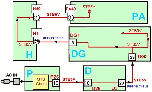
10 10 STB5V Distribution

11 11 STB5V Test Point (P board)

12 12 STB5V Test Point (PA board)

13 Power Supply (Standby Circuit) 13 Tuner SUB ON = Command to turn the relays on.

14 F-STB-ON (Primary) T404 H H H L L H 14

15 15 F-STB-14V and PFC Test Points

16 F-STB-14V H L 16

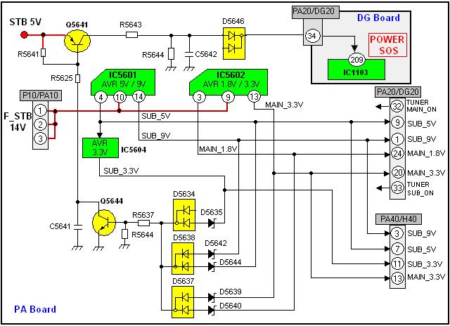
17 SUB-Voltages Output From the PA Board 17
18 18 PA Board Test Points

19 19 Power On/Off Operation

20 20 Power Off
21 21 Power On

22 Power Supply Secondary Circuit (1) L H 22

23 23 Power Supply Secondary Circuit (2)

24 24 Power Supply Connectors

25 25 PA board Circuit Explanation

26 Main-Voltages Output From the PA Board 26
27 No Power Troubleshooting Chart Can the click sound from the relays be heard after the TV is plugged into the wall outlet? No Yes Is there 5V at pin 1 of connector PA40 on the PA board? Wait for approx. 20 seconds after applying AC to the TV. Then turn the power on. Yes Is there 2.5V at pin 13 of connector P25 on the P board? Yes Replace the P Board. No Replace the DG Board. No Replace the P Board. No Replace the D Board. Can the click sound from the relays be heard while attempting to turn the power on? No Is there 3.3V at pin 1 of connector HC01 on the HC board? No Yes Is there 2.5V at pin 17 of connector P25 on the P board? Yes Replace the P Board. Yes 27
28 Shutdown Detect Circuits Understanding how the SHUTDOWN circuit works SOS 28
29 What will normally cause the TV to shut down? A short circuit on any of the voltage lines An over-voltage condition Abnormality in the Control Drive Pulse circuit (SC, SU, SD, and SS boards) 29
30 ases When Missing Voltages Can Cause the TV to Shut Down Missing the source voltage to the PA board (STB14V) from the P board Missing output voltage from the PA board to the DG board. Missing 15V or VSUS on either the SS or SC boards while the control drive pulses from the D board are being provided 30


31 Cases When Missing Voltages Can Cause the TV to Shut Down If the SUB 5V, SUB 9V or MAIN 3.3V is missing on the DG Board, the unit goes into shutdown. The power LED blinks ten times. The voltages are monitored on the DG board by the MPU, IC1103. TPS5V SUB 5V TPM3.3V MAIN 3.3V TPS9V SUB 9V 31
32 TV Shutdown due to Over-voltage or Short Circuit This could happen if there s a short circuit in one of the B+ lines from the PA board, an over-voltage condition, or missing STB 14V from the P board. 32

33 PA Voltage Output If any of the SUB or MAIN voltages that are highlighted on the DG Board is missing, the unit goes into shutdown. The power LED blinks ten times. If any of the voltages created on the PA Board is excessive or shorted, the unit goes into shutdown. The power LED blinks ten times. 33

34 TV Shutdown due to Over-voltage or Short-circuit The base of Q5642 being low indicates a short circuit in the Main 1.8V, Main 9V, or Main 5V output of the PA board. The base of Q5641 being low indicates a short circuit or an over-voltage condition in the NR14V, Main 1.8V, Main 3.3V, SUB 9V, SUB 3.3V or SUB 5V output of the PA board. 34
35 35 PA SOS Detect Circuit

36 PA-Board_Loss of Sub-Voltage Protection 36
37 37 PA Board_Over-Voltage Protection
38 To rule out the P board (Use a Peak Hold Meter for voltage reading) Note: Follow this procedure when the click sound of the relay can be heard after the unit is plugged in. If the relay does not click, check the STB 5V from the P board. If the STB 5V is missing, the P board may be defective. (If STB 5V is OK, the DG board may be defective.) Disconnect connector P10 in the P board (Make sure the TV is unplugged). Because you only have 2 to 3 seconds to measure the STB 14V, place your meter s probe at pin 1 of connector P10 on the P board before plugging the TV to the AC line. Plug the TV to the AC line while still holding the probe at pin 1. Check to see if the 14V comes up. If it doesn t come up, the P board is defective. If it does, (since it may take some involvement to determine which of the PA or the DG board is defective) it s OK to order Both the DG and PA boards together. 38
39 DT, DG, H Board Assembly GND DT10 DG5 DG3 PA40 SL Connector WL Connector DT Board DG Board H Board G51 Connector 39
40 Removal of Board Assembly To uninstall the board assembly, remove the 7 screws indicated by the red circles 40
 Hidden Connector")
41 Board Assembly (Hidden Connector) Hidden Connector DG51 41

42 Board Layout Without the Assembly
43 Power LED blinks 10 times When the power LED blinks 10 times right after the TV has been plugged-in into the AC line and the Power is OFF, the P, the PA, the DG, the H, or the DT may be defective. DT Board DG Board H Board The DT, DG, and H board are part of the assembly. For troubleshooting, the DT board must be removed. 43
44 To rule out the H board: Disconnect connector H40 and plug the TV into the AC line Note: If the Power LED stops blinking, the H board may be defective. If the power LED still blinks, See the next slide. Keep in mind, every time the H board is suspected to be defective, change both the PA and the H board at the same time before applying power to the unit. 44
45 Power LED blinks 10 times To rule out the DT board (Digital Tuner): 1. Remove the screws securing the DT board. Plug the TV into the AC line. 2. Note: If the Power LED stops blinking, the DT board may be defective. 3. Note: When the DT board is removed, the unit will power up with all functions disabled due to a lack of data communication. 4. If the Power LED still blinks, it is possible that the problem is the PA or the DG board. 45

46 46 10 Blinks Due to VSUS or VDA Voltage
47 Power LED blinks 5 times This is caused by abnormalities on the 5V line. This could also happen if the VDA voltage is shorted. SOS 47

48 48 5V, VDA, Data, Scan, Sustain Distribution
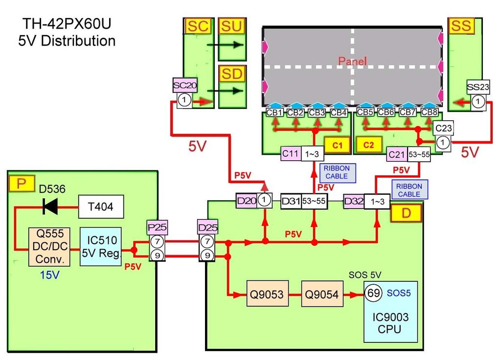
49 49 5V Distribution

50 50 5V SOS Detection Circuit
51 Other Causes of 5V SOS The Power LED could also blink 5 times if the VDA voltage is shorted [Normally by the Panel (de-multiplexer ICs)]. To understand the reason, see the next slide 51
52 52 5V and VDA Distribution on the C Board
53 How to properly isolate the C boards When the ribbon cables from the D board to the C boards are disconnected in order to isolate the C boards, the Power LED will blink 6 times. The following circuit explains the reason why. To properly isolate the C boards without having the Power LED blink, the test point TP9387 (Labeled TP9387 on the D board) should be grounded through a 1K resistor. The VDA connector should be also disconnected. 53

54 54 Drive Reset Circuit


55 Drive Reset Circuit Test Point Foil Side of the D Board TP9387 is not shown on the board. The test point shown in these pictures is a substitute for TP9387. It is located on the foil side of the board. To make the ground connection, the board has to be removed. 55
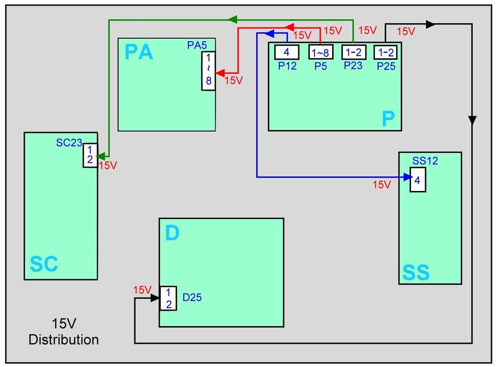
56 56 15V Distribution
57 57 15V SOS Detection Circuit

58 Sound SOS Detection Circuit SOS N N SOS 58

59 Fan SOS 2 59
60 Fan SOS To determine if a fan is the cause of the 11 blinks of the power LED, simply use a peak-hold voltmeter to determine if pin 3 of the fan connector goes High before shutdown. If it does, the fan is defective. If it does not, check the other fans and the fan drive drive circuit. 60
 or L (Low) =")
61 D Board SOS Detect L 3.2V L L L H L H H L H H H L L H (High) or L (Low) = Logic State during normal operation 61

62 DG Board SOS Detect 3.2V L L H H H L L L 62

63 Origin of Power LED Blinks DT
64 D Board SOS Detect D Board SOS Detect SOS LINE LINE MONITORED NUMBER OF TIMES THE POWER LED BLINKS SOS 2 15V 2 BLINKS SOS 3 P3.3V (15V & STB5V) 3 BLINKS SOS 4 PS 4 BLINKS SOS 5 5V 5 BLINKS SOS 6 SC1 6 BLINKS DRVRST 5V DET 6 BLINKS SOS 7 SC2 7 BLINKS SOS 8 SS 8 BLINKS SOS 9 CONF. DC LEVEL SHIFTER 9 BLINKS? 64
65 DG Board SOS Detect DG Board SOS Detect SOS LINE LINE MONITORED NUMBER OF TIMES THE POWER LED BLINKS STB 3.3V DET STB 3.3V 10 BLINKS MAIN 3.3V DET MAIN 3.3V 10 BLINKS SUB 5V DET SUB 5V 10 BLINKS SUB 9V DET SUB 9V 10 BLINKS PA-TUNER SOS PA & TUNER+30V 10 BLINKS FAN SOS FAN CIRCUIT 11BLINKS SOUND SOUND OUT CIRCUIT 12 BLINKS 65

66 No video, No OSD Determining whether a No video, No OSD symptom is caused by the video process or the panel drive circuit 1. Unplug the unit from the wall outlet. 2. Disconnect the connector DG5 from the DG board. 3. Plug the unit into the wall outlet and turn on the power. 4. If the unit displays a white screen, It is a video process problem. 5. If the unit does not display a white screen, Proceed to check the panel drive circuits. 66

67 67 Electrical Location of Connector DG5

68 Physical Location of Connector DG5 DG5 68

69 Physical Location of Connector DG5 (Close-Up View) DG5 69
70 Isolation of the SC and SS Boards If any of the connectors providing the 15V or VSUS voltage to the SC or SS board is disconnected while the connectors that provide the Scan and Sustain Drive pulses from the D board are still connected, the TV will shut down. 70
71 Isolation of the SC and SS Boards Precaution: Do not let the TV run for more than 30 seconds while isolating any of the circuit boards. The Scan Board (SC) and the Sustain (SS) board could be easily isolated. This can be useful to diagnose: 1. Shutdown Problems 2. Video Problems. 71
 15V (Connector SC23) From Power Supply (P board) Scan Control Pulses = Connector SC20 from the SC")
72 Isolation of the SC Board Connector Location The SC board could be isolated from the sources (Supplied Voltage & Scan Control Pulses) Supplied Voltage = VSUS (Connector SC2) 15V (Connector SC23) From Power Supply (P board) Scan Control Pulses = Connector SC20 from the SC board 72
73 SC2, SC23, and SC20 Disconnected SC board completely isolated from the sources (P and D boards) 73 This is useful when the Power LED Blinks 6 or 7 times.
74 Expectation when Isolating the SC Board The Supplied voltage VSUS and 15V (SC2 & SC23) cannot be disconnected while the Scan Control pulses (SC20) are being supplied to the SC board. This will cause a shutdown condition. If only SC2 is disconnected while SC23 and SC20 are connected: The Power LED blinks 6 Times If only SC23 is disconnected while SC2 and SC20 are connected: The Power LED blinks 7 Times Power LED If both SC2 and SC23 are disconnected while SC20 is still connected: The Power LED blinks 7 Times If SC20 is disconnected while SC2 and SC23 are still connected: The Power turns ON (Black Picture No OSD Sound is OK, and there should be video out of the Monitor Jack)) SS LED is ON and SC LED is OFF 74

75 Isolation of the SC Board The SC board could be isolated from the Driver Boards (SU &SD) Sometimes the TV goes into Shutdown indicating that the problem is located on the SC board. This does not necessarily means that the SC board is the cause of the problem. 75 When this occurs, Disconnect both the SU and the SD boards from the SC board. Note: To disconnect, remove 2 screws holding each of these boards in place and disconnect SC41, SU45, SD46 and SC42.

76 Isolation of the SC Board The SC board could be isolated from the Driver Boards (SU &SD) Sometimes the TV may not go into Shutdown when there is a scan problem. This symptom seems to be caused by a defective D or SC board. When in reality, it is caused by the SU board. Disconnecting the SU board yields a good picture at the bottom half of the screen and a completely black area in the upper half of the screen. When this occurs, disconnect the SU board from the SC board. Note: To disconnect, remove 2 screws holding the boards in place and disconnect SC41, SU45. 76

77 Isolation of the SU Board Defective SU 77

78 Display Problem Please no wild guess _ 1. What is the cause of this symptom? 2. How do you isolate a problem of this kind? 78


79 Isolation of the SD Board Please no wild guess _ 1. What is the cause of this symptom? 2. How do you isolate a problem of this kind? 79


80 Supply Voltage from P to SS board SS12 P11 VSUS P12 VDA 15V STB12V SS11 To completely isolate the SS board: 1. Disconnect P12 and P11 on the P board and SS23 on the SS board. VDA SS23 SS34 2. Place a jumper at pin 8 and 10 of connector P12. 5V AND SUSTAIN PULSES The screen is black because there is no VDA voltage from P12 of SS23 provided to the C boards. 80

81 Supply Voltage from P to SS board If P12 or SS12 is disconnected, pin 8 should be connected to pin PLACE A JUMPER ACROSS PIN 8 and PIN 10 of CONNECTOR P12 on the P-BOARD CN SS34 STB12V JUMPER Or MOVE THE JUMPER FROM SS34 TO PIN 8 and PIN 10 of CONNECTOR P12
82 No output to SS board from the D board CN SS23 NO 5V AND SUSTAIN PULSES to SS BOARD CN SS34 STB12V JUMPER NO VDA TO C BOARDS 82 Only SS23 Disconnected

83 No output to SS board from D board 83 Only SS23 Disconnected

84 No output to SS board from D board No Sustain Control Pulses and No VSUS 84 Pin 1 from P12 provides the VDA voltage to SS board

85 85 Defective D board

86 86 Defective D board

87 87 Defective D board

88 88 SC Board

89 89 SC Board

90 90 Defective DG board


91 Forum Thank you for your participation 91
Technical Guide Plasma (GPH10DU Chassis) Troubleshooting Handbook
 Troubleshooting Handbook") Technical Guide Plasma (GPH10DU Chassis) Troubleshooting Handbook Model : TH-42PX75U TH-50PX75U TH-42PX77U TH-50PX77U Panasonic Services Company National Training Prepared by Panasonic Service and Technology
Technical Guide Plasma (GPH10DU Chassis) Troubleshooting Handbook Model : TH-42PX75U TH-50PX75U TH-42PX77U TH-50PX77U Panasonic Services Company National Training Prepared by Panasonic Service and Technology
11 th Generation Full High Definition Plasma Display TV
 11 th Generation Full High Definition Plasma Display TV This Seminar covers the following models: TH-42PX80U, TH-50PX80U, TH-42PZ80U, TH-46PZ80U TH-50PZ80U, TH-42PZ85U, TH-46PZ85U, and TH50PZ85U Panasonic
LIFI LCD Projection TV Service Training Guide
 LIFI LCD Projection TV Service Training Guide LIFI series LIFI = LIght FIdelity Contents: Service Policy Board Access No Start Up Shutdown Service Mode Adjustments 720p PT-50LCX7 PT-56LCX7, 70 PT-56LCX7,
Treadmill Embedded Touch Screen Won t Power Up
 Treadmill Embedded Touch Screen Won t Power Up E-TRe and E-TRxe This document contains the necessary information to troubleshoot a treadmill with an embedded touch screen that will not power up. Follow
2005 Pioneer Home Audio Seminar VSX49TX
 2005 Pioneer Home Audio Seminar VSX49TX Pioneer Electronic Service, Inc. 2005 Introduction Why the VSX49TX? The VSX49TX is not current product, however it tends to be the most difficult to repair! What
Test ROM for Zaccaria 1B1165 CPU Board
 Introduction Test ROM for Zaccaria 1B1165 CPU Board Version 1.2 13 June 2008 David Gersic http://www.zaccaria pinball.com One of the challenges to working on an unknown CPU board is that Zaccaria's software
Plasma Panel Replacement Guide DU-42PX12X
 Plasma Panel Replacement Guide DU-42PX12X Panel Replacement: At this point, the panel has been determined to be defective and replacement is necessary. Upon receiving the replacement panel, it must be
RMV ELECTRONICS INC. Application Note
 RMV ELECTRONICS INC. Application Note Description: Using more than one ITC232-A on the same Serial Port Application #: 00023 Date: May 1994 Status: Final Version This App note has been super-seeded by
Trouble Shooting. Symptoms: Gate Access Control Computer connected to the Facility Computer
 Trouble Shooting Symptoms: Gate Access Control Computer connected to the Facility Computer "Unable to read from controller (CTS lost)" error message on computer screen Do Power checks Do controller (computer
Allworx 24x Service and Troubleshooting Guide
 Allworx 24x Service and Troubleshooting Guide -PAGE INTENTIALLY LEFT BLANK- Table of Contents 1 Safety Instructions...1 1.1 Electrical...1 1.2 Electrostatic Discharge...1 2 Chassis Views...2 3 Exterior
Vector Drive - Troubleshooting Guide
 Haas Technical Documentation Vector Drive - Troubleshooting Guide Scan code to get the latest version of this document Translation Available The Haas Vector drive is the source of power for the spindle
Vector Drive - Troubleshooting Guide
 Haas Technical Documentation Vector Drive - Troubleshooting Guide Scan code to get the latest version of this document Translation Available The Haas Vector drive is the source of power for the spindle
PDP One Point Repair Guide ~ 42 Inch Practice Inch Practice
 PDP One Point Repair Guide 1. 40 ~ 42 Inch Practice 2. 60 Inch Practice P6 cause : bad connection between Y-Board # 1, 2 drive board Connector pin Rework should be done P4 Y-Driver Board Y-Board P 6 P
Blue Point Engineering
 Blue Point Engineering Board - Pro Module (E) Instruction Pointing the Way to Solutions! Controller I Version 2.1 The Board Pro E Module provides the following features: Up to 4 minutes recording time
Perform general SC916 electrical testing. With external power removed, step on one or both of the pedal arms
 Perform general SC916 electrical testing With external power removed, step on one or both of the pedal arms the console turn on? battery in a charged state? Using external power supply, charge battery
TARA CONTROLS AGC-5. UCI Random Start USER S GUIDE. With Optional Warning Flashes for the Hearing Impaired. TARA CONTROLS by Cartessa Corporation
 TARA CONTROLS AGC-5 UCI Random Start USER S GUIDE With Optional Warning Flashes for the Hearing Impaired TARA CONTROLS by Cartessa Corporation 4825 Cincinnati-Brookville Road Shandon, Ohio 45063 Phone:
Air Hockey v7.0 Controller PCB Air Hockey 10v Transformer
 KNOWN ISSUES SORTED BY BOARD REVISION DYNAMO HOCKEY PCBs LISTED IN THIS WORKSHEET are no longer available for purchase or serviced by the manufacturer. Most tables can be upgraded to Dynamo s latest v7.0
Fast Track Troubleshooting Manual Rev 6/25/12 SMPS SPEAKER- L SERVICE BULLETINS
 UN40EH5000FXZA Fast Track Troubleshooting Manual Rev 6/25/12 MAIN LVDS SMPS -FIRMWARE: 6/4/2012 Version 1012.3-2012 LED TV X9N Full HD Firmware (T-MX9FAUSC_1012.3) - Makes better picture quality and solves
Pro-HD Model E. Troubleshooting Guide. ProHD chargers with a serial number that begins with an E are model E systems. Example:
 Pro-HD Model E Troubleshooting Guide ProHD chargers with a serial number that begins with an E are model E systems. Example: WARNING: During these troubleshooting tests the system can be plugged in and
Installation Instructions
 Installation Instructions Cat. No. 1771 P3, P4, P5 and P5E Use this document as a guide when installing the catalog number 1771-P3, -P4, -P5 or -P5E power supplies. Because of the variety of uses for the
RPX Series USER S MANUAL
 RPX Series USER S MANUAL INDEX 1.1 Introduction page 1 1.2 Packing page 1 1.3 Drawing page 2~16 1.4 Features page 17 1.5 Specification page 18~21 1.6 Installation & Testing page 22~23 1.7 Hot-Swap Procedures
HVG400. Installation Guide
 HVG400 Installation Guide September 2013 Trademarks & Copyright Trademarks All trademarks mentioned in this manual are the sole property of their respective manufacturers. Copyright Ltd., Jerusalem, Israel
ELECTRICAL SUPPLY TROUBLESHOOTING QUICK GUIDE SAFETY PRECAUTIONS
 ELECTRICAL SUPPLY TROUBLESHOOTING QUICK GUIDE 1. Circuit Breaker Tripping 2. Circuit Overload 3. Short Circuit 4. Ground Fault 5. Ground Fault Circuit Interrupter (GFCI) Tripping SAFETY PRECAUTIONS Basic
Parts List: Assembly Instructions:
 My Ride SERVICE MANUAl MyRide ASSEMBLY GUIDE 1.1 ASSEMBLY INSTRUCTIONS ASSEMBLING THE MYRIDE Parts List: Heavy Plate Stabilizer Fin - Right Stabilizer Fin - Left Stabilizer Fin - Large Middle Power Cord
QCPort Cover Control Trouble Shooting Guide
 QCPort Cover Control Trouble Shooting Guide Technical Document Feb. 2006 Page 1 of 14 QCPort Cover Control Description Door Defeater Address/Options Bucket Latch Breaker Actuator Hasp Lock Keypad Overlay
AirTest Model CN9000 Series Sensor Controller
 AirTest Model CN9000 Series Sensor Controller AirTest Model CN9000 Series Sensor Controller THEORY OF OPERATION A basic CN9000 configuration consists of Input/Process/Display combination modules, a 3 relay
Start Relay Circuit - Test
 Start Relay Circuit - Test System Operation Description: Use this procedure to troubleshoot any suspect problems with the circuit for the start relay. This procedure covers the following diagnostic codes:
C580R/U Cycle Trainer Repair Manual SPORTS ART INDUSTRIAL CO., LTD.
 C580R/U Cycle Trainer Repair Manual SPORTS ART INDUSTRIAL CO., LTD. Table of Contents 1. Component Placement Illustrations 1-1-1. C580R Unit Illustration 1-1-2. C580U Unit Illustration 1-1-3. C580R Component
3. Alignment and Adjustments
 3. 3-1 Test Mode How to Approach Test Mode You can approach the Test Mode by pressing the on/off switch of indoor unit for 5 seconds. on/off switch Test Mode Operation Option After installing the air conditioner,
Pico Amiga ATX power adaptor install guide
 Pico Amiga ATX power adaptor install guide Introduction The ATX power adaptor allows you to power your Amiga A500/A600/A1200 or CD32 from a modern ATX power supply. This variant of the design has a right
OPERATING INSTRUCTIONS AND SERVICE MANUAL BASKETBALL SHOTCLOCK MODEL MP-5299
 OPERATING INSTRUCTIONS AND SERVICE MANUAL BASKETBALL SHOTCLOCK MODEL MP-5299 EFFECTIVE S.N. 17,000, December, 2000 TABLE OF CONTENTS 1. General Information 1.1 Description 1.2 Identification 1.3 Damage
2.1 Start of Call. IBM Network Printer 17
 General 2.1 Start of Call Ver. 8/27/96 Page 2-1 2 General 2.1 Start of Call This is the entry point for all fault isolation procedures (FIPs), service mode diagnostics and factory adjustments, and general
Wiring Instructions. Gatekeeper h4.0. Technical Support.
 Wiring Instructions Gatekeeper h4.0 Technical Support support@gymmastersoftware.com USA: 415 678 1270 Australia: 03 9111 0323 : 03 974 9169 Copyright 2016 Treshna Enterprises. All rights reserved. Table
TURN-O-MATIC INSTALLATION GUIDE
 TURN-O-MATIC INSTALLATION GUIDE WIRELESS SYSTEM WIRELESS SYSTEM (1) Dispenser (1) Dispenser Mounting Bracket (3) Large Slotted Screw (2) Large Slotted Bolt (2) Nut (1) Display Wall Mount Bracket (1) Wireless
Connecting a Cisco Output Module
 CHAPTER 5 Overview The optional Cisco Output Module (Figure 5-1) is attached to a Cisco Physical Access Gateway or Cisco Reader Module to provide additional connections for up to 8 outputs, each of which
VC2100 / VC MB Digital Event Recorder
 VC2100 / VC2100 32MB Digital Event Recorder Product Description: This system includes one VS2100 single channel digital event recorder and one color camera. It will automatically have image capture or
SERIES 5100 INSTALLATION & SPECIFICATION GUIDE
 SERIES 5100 INSTALLATION & SPECIFICATION GUIDE Microframe Corporation 604 South 12th Street Local: 918-258-4839 Toll Free: Website: www.microframecorp.com E-mail: support@microframecorp.com Manual No.
Owner s Manual DA-300USB D/A CONVERTER. Appendix. Contents. You can print more than one page of a PDF onto a single sheet of paper.
 DA-300USB D/A CONVERTER Owner s Manual You can print more than one page of a PDF onto a single sheet of paper. Front panel Display Rear panel Contents Accessories 3 Features 4 High quality sound 4 High
First of all, thank you for purchasing R2W series redundant power supply.
 1.1 INTRODUCTION First of all, thank you for purchasing R2W series redundant power supply. The R2W series is a 1+1 hot-swappable / hot-pluggable redundant power supply. It consists of, 1) complete metal
Arrakis Systems 6604 Powell Street / Loveland, Colorado 80538
 Arrakis Systems 6604 Powell Street / Loveland, Colorado 80538 Input and Output wiring for the 150sc, 500sc, 2000sc and 2100sc audio consoles. A Input Channel Wiring (Back of Console) 6. Left Input 5. Left
ATLD10A5-D EV1.0 Evaluation Board for ATLD10A5-D 10A High Efficiency Laser Controller ATLD10A5-D Evaluation Board Rev. 1.0
 ATLD0A5-D EV.0 Evaluation Board for ATLD0A5-D 0A High Efficiency Laser Controller ATLD0A5-D Evaluation Board Rev..0 Figure ATLD0A5-D EV.0 Photo INTORDUCTION The ATLD0A5-D is an electronic module designed
Panasonic. DVD/DVC Camera Seminar VDR-D100/200/300 and PV-GS29/39
 Panasonic DVD/DVC Camera Seminar VDR-D100/200/300 and PV-GS29/39 Features (VDR-D100~300) DVD Multi DVD-RAM/R/-RW DSC Feature (Disc & SD Card) One Touch Navigation & Joystick Built in Video Light (D105&D200
Gottlieb Universal Test Board
 Gottlieb Universal Test Board Tester Overview The Gottlieb Universal Test Board is a design original created by Leon Borre to help diagnose Gottlieb System 80 MPU boards. It connects to the TC1 connector
SERIES 5100XXX8 INSTALLATION & SPECIFICATION GUIDE
 SERIES 5100XXX8 INSTALLATION & SPECIFICATION GUIDE Microframe Corporation 604 South 12th Street Local: 918-258-4839 Toll Free: Website: www.microframecorp.com E-mail: support@microframecorp.com Revision
KS-SB200 BOOM BOX INSTRUCTIONS LVT B [J]
![KS-SB200 BOOM BOX INSTRUCTIONS LVT B [J]](/thumbs/72/66806114.jpg "KS-SB200 BOOM BOX INSTRUCTIONS LVT B [J]") BOOM BOX KS-SB200 INSTRUCTIONS For Customer Use: Enter below the Model No. and Serial No. which are located either on the rear, bottom or side of the cabinet. Retain this information for future reference.
BOOM BOX KS-SB200 INSTRUCTIONS For Customer Use: Enter below the Model No. and Serial No. which are located either on the rear, bottom or side of the cabinet. Retain this information for future reference.
This document describes the procedure for doing a power trace on the SM5 and Gauntlet Stepmills.
 SM5/Gauntlet Stepmill Power Trace Applies to: SM5 (150005) + Gauntlet (150015) This document describes the procedure for doing a power trace on the SM5 and Gauntlet Stepmills. Latest Rev. Warning: the
MEGATRONICS V3.0 QUICK START GUIDE
 MEGATRONICS V3.0 QUICK START GUIDE Thank you for purchasing the Megatronics v3.0! This small guide will answer the basic questions on how to connect the board to your 3D printer. For more information visit
Wiring Instructions v3
 Wiring Instructions v3 Gatekeeper h4.1 Technical Support support@gymmastersoftware.com USA: 415 678 1270 Australia: 03 9111 0323 : 03 974 9169 Copyright 2017 Treshna Enterprises. All rights reserved. Table
Bluetooth Sound Bar with Built-in Subwoofer Model: SB210
 Bluetooth Sound Bar with Built-in Subwoofer Model: SB210 Package Contents Bluetooth Sound Bar with Built-in Subwoofer Remote control 2 AAA batteries Power adaptor Stereo 3.5mm audio cable Stereo RCA audio
42PQ30 Plasma Display
 Training Manual 42PQ30 Plasma Display Advanced Single Scan Troubleshooting 720p NOTICE: ALL INFORMATION CONTAINED WITHIN THIS PACKAGE IS BASED ON PRE- SALES MODEL. INFORMATION SUBJECT TO CHANGE AT FINAL
SERIES 4600 Ethernet Visual-Pager Display INSTALLATION and SPECIFICATION GUIDE. Manual No. D Revision Date: 08/2016 Control: 1.
 SERIES 4600 Ethernet Visual-Pager Display INSTALLATION and SPECIFICATION GUIDE Manual No. D4600-7010 Revision Date: 08/2016 Control: 1.0 Microframe Corporation 604 South 12th Street Local: 918-258-4839
Table of Contents. Federal Communications Commission (FCC) Statement...2
 Statement...2") Contents Table of Contents Federal Communications Commission (FCC) Statement...2 Important Safety Instructions...3 Chapter 1 Introduction Features...6 Package Contents...7 Front View and Controls...8 Installing
Contents Table of Contents Federal Communications Commission (FCC) Statement...2 Important Safety Instructions...3 Chapter 1 Introduction Features...6 Package Contents...7 Front View and Controls...8 Installing
V-9939C MICROPHONE ADAPTER
 Issue 2 INTRODUCTION These instructions provide identification, installation, connection, operation and maintenance information for the Microphone Adapter. The is a Microphone Adapter designed to be used
629/P32 (X10/P32) PIC CHIP. On - Off Operating Instructions (Revision 2)
 PIC CHIP. On - Off Operating Instructions (Revision 2)") 629/P32 (X10/P32) PIC CHIP On - Off Operating Instructions (Revision 2) This manual is a living document, therefore it will change when needed to clarify and explain the operation of the 629/P32 (X10/P32)
629/P32 (X10/P32) PIC CHIP On - Off Operating Instructions (Revision 2) This manual is a living document, therefore it will change when needed to clarify and explain the operation of the 629/P32 (X10/P32)
Copyright 2017, 2018 HP Development Company, L.P.
 User Guide Copyright 2017, 2018 HP Development Company, L.P. Intel, Thunderbolt, the Thunderbolt logo, and vpro are trademarks of Intel Corporation in the U.S. and/or other countries. NVIDIA is a trademark
Microframe Corporation
 Microframe Corporation Series 160: Booster Amplifier Operating Manual A0160-7011 *A0160-7011* SERIES 160 INSTALLATION & SPECIFICATION GUIDE ITEM NO: A0160-7011 REVISION DATE: 04/02 Microframe Corporation
Repair and Replacement Instructions Genesis Desking Lift System
 Field Service Guide for Lift System Components Controllers, Motors, Cables and Switches Repair and Replacement Instructions KI-62057R1/PDF/309 Used with written consent. Copyright, Suspa Inc., 2002 Before
Firmware Update Manual for Sony Cyber-shot digital still cameras
 Firmware Update Manual for Sony Cyber-shot digital still cameras - DSC-T1 The term Firmware refers to the software in your Cyber-shot camera. You can update this software to solve problems or to add new
ADDENDUM FOR 20, 27, & 28 OPTIONS
 ADDENDUM FOR 20, OPTIONS GENERAL The 20, 27, and 28 option provides for an alarm contact OR an AC transfer switch on EXELTECH XP Series inverters. The alarm relay monitors the inverter s AC output and
Part No. Z , IA Nov OPERATION MANUAL. High Voltage Digitalmeter A
 Part No. Z1-109-920, IA001723 Nov. 2005 OPERATION MANUAL High Voltage Digitalmeter 149-30A Use of Operation Manual Please read through and understand this Operation Manual before operating the product.
Hardware Installation Manual MX Axis Stepper Drive with Breakout Board & I/O s
 Hardware Installation Manual MX3660 3-Axis Stepper Drive with Breakout Board & I/O s Version 1.0 11 / 2013 Hardware Manual for MX3660 3-Axis Stepper Drive with Breakout Board & I/O s ii Notice Read this
Assembly Instructions (8/14/2014) Your kit should contain the following items. If you find a part missing, please contact NeoLoch for a replacement.
 Your kit should contain the following items. If you find a part missing, please contact NeoLoch for a replacement.") NeoLoch NLT-28P-LCD-5S Assembly Instructions (8/14/2014) Your kit should contain the following items. If you find a part missing, please contact NeoLoch for a replacement. Kit contents: 1 Printed circuit
NeoLoch NLT-28P-LCD-5S Assembly Instructions (8/14/2014) Your kit should contain the following items. If you find a part missing, please contact NeoLoch for a replacement. Kit contents: 1 Printed circuit
High Voltage Power Supply (MMPS) - Troubleshooting Guide
 - Troubleshooting Guide") High Voltage Power Supply (MMPS) - Troubleshooting Guide LAST UPDATED: 09/19/2018 High Voltage Power Supply (MMPS) - Troubleshooting Guide Overview The High Voltage Power Supply (MMPS - MINIMILL Power
High Voltage Power Supply (MMPS) - Troubleshooting Guide LAST UPDATED: 09/19/2018 High Voltage Power Supply (MMPS) - Troubleshooting Guide Overview The High Voltage Power Supply (MMPS - MINIMILL Power
Connecting a Cisco Input Module
 CHAPTER 4 Overview The optional Cisco Input Module (Figure 4-1) is attached to a Cisco Physical Access Gateway or Cisco Reader Module to provide additional connections for up to ten input devices. Each
SAT0003_REV3.0 Test Procedure Texas Instruments for TPS40422 EVM Module
 Texas Instruments SAT0003_REV3.1 Test Procedure April 23, 2013 Scott McElroy Note: The SAT0003_REV3.1 is an evaluation module for the TPS40422 using the MSP430G2553 to test the functionality of the PMBus.
RACK-220 CHASSIS USER S MANUAL
 RACK-220 CHASSIS USER S MANUAL 1 Copyright Notice This document and product is copyrighted, Jun 1999, by ICP Electronics Inc. All rights are reserved. No part of this manual may be reproduced, copied,
FCC NOTICE: FCC STATEMENT:
 FCC NOTICE: This equipment has been tested and found to comply with the limits for a Class B digital device, pursuant to Part 15 of the FCC Rules. These limits are designed to provide reasonable protection
DVI Video Switch USER MANUAL VS-261 / VS-461
 DVI Video Switch USER MANUAL VS-261 / VS-461 FCC Information This equipment has been tested and found to comply with the limits for a Class B digital device, pursuant to Part 15 of the FCC Rules. These
S.M.A.R.T. Service Material and Reference Tips
 S.M.A.R.T. Service Material and Reference Tips Product: LCD Date: 2/4/2010 Models: 32RV525RZ, 37RV52R, 37RV52RZ, 37RV525RZ, 40RV52R, 40RV52RZ, 40RV525R, 40RV525RZ, 46RV525R, 46RV525RZ Doc Ref/File: SMART2009-LCD209-V9
MCU-9201MT22 venetian blind controller
 MCU-9201MT22 venetian blind controller It is strongly recommended to read and follow the instructions in this manual carefully, before you start installing or programming a system. Installation, configuration
X/Y Issues on ASP-645-1
 X/Y Issues on ASP-645-1 Issues seen with X or Y problems: A) Table will not move in X or Y when you are using the Frame Arrow buttons on the control panel. B) On power up the control panel gives Error
50PQ30 Plasma Display
 Training Manual 50PQ30 Plasma Display Advanced Single Scan Troubleshooting 720p Published November 05 th, 2009 OUTLINE Section 1 Overview of Topics to be Discussed Contact Information, Preliminary Matters,
3. APPEARANCE AND CONNECTORS
 3. APPEARANCE AND CONNECTORS 3.1. Appearance Winder Operation panel Printer mechanism PNE sensor DC Jack: Plug the AC adapter or DC output plug of the power supply. Power switch: When this Power switch
Computer Assembly (Installing Mother Board & CPU)
") Computer Assembly (Installing Mother Board & CPU) IT@SCHOOL HARDWARE TEAM Biju Thiruvananthapuram Sree Kumar Kottarakkara Shamsudeen Attingal Pradeep Mattara Wandoor Pre-Installation Precaution Mother
Computer Assembly (Installing Mother Board & CPU) IT@SCHOOL HARDWARE TEAM Biju Thiruvananthapuram Sree Kumar Kottarakkara Shamsudeen Attingal Pradeep Mattara Wandoor Pre-Installation Precaution Mother
Harbortronics Time-Lapse Package Troubleshooting Guide This document is intended to help diagnose any problems with your Time-Lapse Package.
 This document is intended to help diagnose any problems with your Time-Lapse Package. Power Everything in the Time-Lapse Package (TLP) is powered by the large Lithium-Ion Polymer battery pack, made specifically
DEV-1 HamStack Development Board
 Sierra Radio Systems DEV-1 HamStack Development Board Reference Manual Version 1.0 Contents Introduction Hardware Compiler overview Program structure Code examples Sample projects For more information,
2100 Multiplex. Troubleshooting
 2100 Multiplex Troubleshooting Manual TABLE OF CONTENTS GENERAL Introduction......3 Outlines......3 Flowcharts......3 OtherTroubleshooting Aids..... 4 OUTLINES FrontPanelOutline... 4 ConsoleOutline...
CHAPTER 3B: ELECTRONIC POWER STEERING
 Electronic Power Steering CHAPTER 3B: ELECTRONIC POWER STEERING NOTE: The basic steering system, such as the tie rod ends, drag links axles, etc., is covered in Chapter 3A: Steering. In 2012, Cub Cadet
Model IMP-22G2,H Low Cost Slave Clock Impulser Converts your slave clock to a working timepiece without modifying its original mechanism.
 Model IMP-22G2,H Low Cost Slave Clock Impulser Converts your slave clock to a working timepiece without modifying its original mechanism. The PIEXX IMP-22G2, H allows you to put your slave clock back into
POWERHOUSE. -- the finest in Digital Command Control -- PRODUCT MANUAL FOR PB-205a DUAL 5AMP POWER STATION
 POWERHOUSE TM -- the finest in Digital Command Control -- PRODUCT MANUAL FOR PB-205a DUAL 5AMP POWER STATION NCE Corporation 1260 CREEK STREET SUITE 100 WEBSTER NEW YORK 14580 FAX : (716) 671-9337 E-mail:
Installation/assembly manual for DCC/Power shield
 Installation/assembly manual for DCC/Power shield The DCC circuit consists of the following components: R1/R6 R2/R3 R4/R5 D1 C2 2 kω resistor ½ Watt (colour code Red/Black/Black/Brown/Brown) 10 kω resistor
MODEL: R1M-A1. PC Recorders R1M Series. SPECIFICATIONS OF OPTION: Q COATING (For the detail, refer to M-System's web site.)
") PC Recorders R1M Series PC RECORDER (contact input, 32 points) Functions & Features Industrial recorder on PC 32-point dry contact inputs Easy system expansion via Modbus RTU Recorded data exportable to
PC Recorders R1M Series PC RECORDER (contact input, 32 points) Functions & Features Industrial recorder on PC 32-point dry contact inputs Easy system expansion via Modbus RTU Recorded data exportable to
The following instructions are for installing the PD DVD Module in PDI P-Series large screen televisions (26, 32 & 40 ).
.") MODEL INSTALLING THE DVD MODULE Page 1 of 8 CAUTION: Disconnect the TV s AC Power Cord from the wall outlet before installing the DVD module. Failure to do so may result in catastrophic damage to the module
MODEL INSTALLING THE DVD MODULE Page 1 of 8 CAUTION: Disconnect the TV s AC Power Cord from the wall outlet before installing the DVD module. Failure to do so may result in catastrophic damage to the module
DS-101g+ Disk Station Quick Installation Guide
 DS-101g+ Disk Station Quick Installation Guide ATTENTION Please refer to Chapter 2 Get to know the Hardware in the User s Guide for the detailed button and LED description. Packing List Before you begin,
Precision DMX Manual
 Precision DMX Manual Updated: December 4, 2012 The Precision DMX is a compact, low voltage, controllable LED fixture that can be connected to any DMX console or be programmed to run standalone without
Sprint User Guide. A downloadable, printable guide to your Sprint Phone Connect 4 and its features.
 Sprint User Guide A downloadable, printable guide to your Sprint Phone Connect 4 and its features. Available applications and services are subject to change at any time. Table of Contents GETTING STARTED
High Power (15W + 15W) Stereo Amplifier
 Stereo Amplifier") High Power (15W + 15W) Stereo Amplifier Build Instructions Issue 1.0 Build Instructions Before you put any components in the board or pick up the soldering iron, just take a look at the Printed Circuit
High Power (15W + 15W) Stereo Amplifier Build Instructions Issue 1.0 Build Instructions Before you put any components in the board or pick up the soldering iron, just take a look at the Printed Circuit
********SERVICE MANUAL******** MODELS:
 ********SERVICE MANUAL******** MODELS: 75211-10 Variable Speed Drive, 5000 RPM, 115 V 75211-15 Variable Speed Drive, 5000 RPM, 230 V, CE Mark 75211-60 Variable Speed Drive w/pump, 9000 RPM, 115 V 75211-62
Supplementary manual UVR16x2E-DE/NP Relay versions
 Technische Alternative RT GmbH A-3872 Amaliendorf, Langestr. 124 Tel +43 (0)2862 53635 mail@ta.co.at UVR16x2E-DE UVR16x2E-NP Manual vers. 1.4 EN Supplementary manual UVR16x2E-DE/NP Relay versions Table
Reference Manual Roland Corporation 01
 Reference Manual 2017 Roland Corporation 01 Panel Descriptions Rubix22 Front Panel 1 2 3 2 1 6 7 8 When connecting a guitar or bass, use the INPUT 1L jack. The sound level will be very low if you connect
AWS DeepRacer Getting Started Guide
 AWS DeepRacer Getting Started Guide 1 Getting Started Guide Contents What s in the box Assemble your car Get connected Test drive Autonomous model management 2 What s in the box 1 2 6 8 9 5 11 10 4 7 3
Integrated Amplifier PM5005
 . Integrated Amplifier PM5005 You can print more than one page of a PDF onto a single sheet of paper. 1 Owner s Manual Accessories 4 Inserting the batteries 5 Operating range of the remote control 5 Features
USER S MANUAL. C32- DUAL PORT MULTIFUNCTION CNC BOARD Rev. 4
 USER S MANUAL C32- DUAL PORT MULTIFUNCTION CNC BOARD Rev. 4 August, 2012 USER'S MANUAL TABLE OF CONTENTS Page # 1.0 FEATURES... 1-1 2.0 SPECIFICATIONS... 2-3 3.0 BOARD DESCRIPTION... 3-4 4.0 FUNCTIONAL
Owner s Hardware Service Manual Frank Control Computer System
 Owner s Hardware Service Manual Frank Control Computer System Revision 0105 ABOUT THIS MANUAL This section describes the contents of this manual and how to use this manual effectively. It was designed
QUICK START GUIDE SP260 QSG 00
 QUICK START GUIDE SP260 QSG 00 Getting to know Bluetooth Bluetooth wireless is a quick and easy way to connect a smartphone to a speaker or a headset. There are basically two steps to making Bluetooth
IST ULTRASTAB Power Supply for high precision transducers
 IST ULTRASTAB Power Supply for high precision transducers High performance 6-channel power supply for multi-channel laboratory measurement applications. Features Current output or ±0 V voltage output (see
Product Manual. Relay Plug
 Product Manual Relay Plug Updated on 24 June 2017 Index Index 1 Introduction 2 Specification 3 Operating voltage: 5V 3 Variants 4 Supported cables: 4 Details 4 How to interface? 5 Example Codes 9 Arduino
Power Supply and Fan Module Installation
 3 CHAPTER This chapter describes how to remove and install a new or replacement power supply or fan module in a Catalyst 3750-E or Catalyst 3560-E switch. See these sections: Installation Overview, page
Microframe Corporation
 Series 906: 6-Digit Visual-Paging System Operating Manual A0906-7010 *A0906-7010* Limited Warranty Agreement Your Microframe System is warranted against failure due to defects in workmanship or material
DREAM 2 WIRED RTU SYSTEM GUIDE
 TALGIL COMPUTING & CONTROL LTD. NAAMAN CENTER, HAIFA - ACCO ROAD ISRAEL P.O. BOX 775 KIRYAT MOTZKIN 26119 TEL: 972-4-8775947-8775948 FAX: 972-4-8775949 DREAM 2 WIRED SYSTEM GUIDE 2007 1 CONTENTS 1. SYSTEM