Operating Instructions
|
|
|
- Rosalind Clark
- 5 years ago
- Views:
Transcription
1 Operating Instructions VLT Micro Drive FC 51
2
3 VLT Micro Drive FC 51 Operating Instructions Contents Contents 1. Safety 5 Safety Instructions 5 Approvals 5 General Warning 5 Avoid unintended Start 6 Before Commencing Repair Work 6 2. Mechanical Installation 7 Before Starting 7 Mechanical Dimensions 8 3. Electrical Installation 9 How to Connect 9 Electrical Installation in General 9 EMC-Correct Installation 10 Mains Connection 11 Motor Connection 11 Control Terminals 12 Connecting to Control Terminals 13 Switches 13 Power Circuit - Overview 14 Load sharing/brake Programming 15 How to Programme 15 Programming with MCT Programming with LCP 11 or LCP Status Menu 17 Quick Menu 17 Quick Menu Parameters 17 Main Menu Modbus RTU 23 Modbus RTU Overview 23 Modbus RTU Message Framing Structure 24 Remote Terminal Unit 24 Modbus RTU Message Structure 24 Start/Stop Field 24 Address Field 24 Function Field 25 Data Field 25 MG.02.A VLT is a registered Danfoss trademark 1
4 Contents VLT Micro Drive FC 51 Operating Instructions CRC Check Field 25 Coil/Register Addressing 25 How to Control FC Function Codes Supported by Modbus RTU 27 Exception and Error Codes 27 How to Access Parameters 28 Parameter Handling 28 Storage of Data 28 IND 28 Text Blocks 28 Conversion Factor 28 Parameter Values 28 Examples 29 Read Coil Status (01HEX) 29 Force/Write Single Coil (05HEX) 29 Force/Write Multiple Coils (0FHEX) 30 Read Holding Registers (03HEX) 31 Preset Single Register (06HEX) 31 Preset Multiple Registers (10HEX) 32 Danfoss FC Control Profile 33 Control Word According to FC Profile 33 Explanation of the Control Bits 33 Status Word According to FC Profile (STW) 35 Explanation of the Status Bits 35 Bus Speed Reference Value Parameter Overview 39 Conversion Index 43 Change during operation 43 2-Set-up 43 Type 43 0-** Operation/Display 44 1-** Load/Motor 45 2-** Brakes 46 3-** Reference/Ramps 47 4-** Limits/Warnings 48 5-** Digital In/Out 49 6-** Analog In/Out 50 7-** Controllers 51 8-** Comm. and Options ** Smart Logic 53 2 MG.02.A VLT is a registered Danfoss trademark
5 VLT Micro Drive FC 51 Operating Instructions Contents 14-** Speical Functions ** Drive Information ** Data Readouts Troubleshooting 57 Alarm Word and Extended Status Word Specifications 59 Mains Supply 59 Other Specifications 61 Special Conditions 63 The Purpose of Derating 63 Derating for Ambient Temperature 63 Derating for Low Air Pressure 63 Derating for Running at Low Speeds 63 Options for VLT Micro Drive FC Index 65 MG.02.A VLT is a registered Danfoss trademark 3
6 1. Safety VLT Micro Drive FC 51 Operating Instructions 1 4 MG.02.A VLT is a registered Danfoss trademark

7 VLT Micro Drive FC 51 Operating Instructions 1. Safety 1. Safety High Voltage Warning 1 The voltage of the frequency converter is dangerous whenever it is connected to mains. Incorrect installation of the motor or frequency converter may cause damage to the equipment, serious injury or death. Consequently, it is essential to comply with the instructions in this manual as well as local and national rules and safety regulations Safety Instructions Make sure the frequency converter is properly connected to earth. Do not remove mains connections, motor connections or other power connections while the frequency converter is connected to power. Protect users against supply voltage. Protect the motor against overloading according to national and local regulations. The earth leakage current exceeds 3.5 ma. The [OFF] key is not a safety switch. It does not disconnect the frequency converter from mains Approvals General Warning Warning: Touching the electrical parts may be fatal - even after the equipment has been disconnected from mains. Also make sure that other voltage inputs have been disconnected, (linkage of DC intermediate circuit). Be aware that there may be high voltage on the DC link even when the LEDs are turned off. Before touching any potentially live parts of the VLT Micro Drive, wait at least 4 minutes for all sizes. Shorter time is allowed only if indicated on the nameplate for the specific unit. Leakage Current The earth leakage current from the VLT Micro Drive FC 51 exceeds 3.5 ma. According to IEC a reinforced Protective Earth connection must be ensured by means of a min. 10mm² Cu or an addtional PE wire - with the same cable cross section as the Mains wiring - must be terminated separately. Residual Current Device This product can cause a D.C. current in the protective conductor. Where a residual current device (RCD) is used for extra protection, only an RCD of Type B (time delayed) shall be used on the supply side of this product. See also Danfoss Application Note on RCD, MN. 90.GX.YY. Protective earthing of the VLT Micro Drive and the use of RCDs must always follow national and local regulations. Motor overload protection is possible by setting Parameter 1-90 Motor thermal protection to the value ETR trip. For the North American market: ETR functions provide class 20 motor overload protection, in accordance with NEC. MG.02.A VLT is a registered Danfoss trademark 5

8 1. Safety VLT Micro Drive FC 51 Operating Instructions 1 Installation in high altitudes: By altitudes above 2km, please contact Danfoss Drives regarding PELV IT Mains IT Mains Installation on isolated mains source, i.e. IT mains. Max. supply voltage allowed when connected to mains: 440 V. As an option, Danfoss offers line filters for improved harmonics performance Avoid unintended Start While the frequency converter is connected to mains, the motor can be started/stopped using digital commands, bus commands, references or via the Local Control Panel. Disconnect the frequency converter from mains whenever personal safety considerations make it necessary to avoid unintended start of any motors. To avoid unintended start, always activate the [OFF] key before changing parameters Disposal Instruction Equipment containing electrical components must not be disposed of together with domestic waste. It must be separately collected with electrical and electronic waste according to local and currently valid legislation Before Commencing Repair Work 1. Disconnect FC 51 from mains (and external DC supply, if present.) 2. Wait for 4 minutes for discharge of the DC-link. 3. Disconnect DC bus terminals and brake terminals (if present) 4. Remove motor cable 6 MG.02.A VLT is a registered Danfoss trademark
9 VLT Micro Drive FC 51 Operating Instructions 2. Mechanical Installation 2. Mechanical Installation 2.1. Before Starting Checklist 2 When unpacking the frequency converter, make sure that the unit is undamaged and complete. Check that the packaging contains the following: VLT Micro Drive FC 51 Quick Guide Optional: LCP and/or de-coupling plate. Illustration 2.1: Content of box Side-by-Side Installation The Danfoss VLT Micro Drive can be mounted side-by-side for IP 20 rating units and requires 100 mm clearance above and below for cooling. Regarding surroundings in general, please see chapter 7. Specifications. Illustration 2.2: Side-by-side installation. MG.02.A VLT is a registered Danfoss trademark 7
10 2. Mechanical Installation VLT Micro Drive FC 51 Operating Instructions Mechanical Dimensions 2 Illustration 2.3: Mechanical dimensions. NB! A template for drilling can be found on the flap of the packaging. Power (kw) Height (mm) Width (mm) Depth 1) (mm) Max. Weight Frame 1 X X 3 X A (incl. decoupling plate) A V V V a B b C Kg M M M ) 2) 2) 2) 2) 2) 2) Table 2.1: Mechanical Dimensions 1) For LCP with potentiometer, please add 7.6 mm. 2 These dimensions will be announced at a later point. NB! DIN rail mounting kit is available for M1. Please use ordering number 132B MG.02.A VLT is a registered Danfoss trademark
11 VLT Micro Drive FC 51 Operating Instructions 3. Electrical Installation 3. Electrical Installation 3.1. How to Connect Electrical Installation in General NB! All cabling must comply with national and local regulations on cable cross-sections and ambient temperature. Copper conductors required, (60-75 C) recommended. 3 Details of terminal tightening torques. Power (kw) Torque (Nm) Frame 1 x x x DC connection/brake minals Control Ter- Line Motor V V V Earth Relay M M M ) Spade connectors Table 3.1: Tightening of terminals Fuses Branch circuit protection: In order to protect the installation against electrical and fire hazard, all branch circuits in an installation, switch gear, machines etc., must be short-circuited and overcurrent protected according to national/international regulations. Short circuit protection: Danfoss recommends using the fuses mentioned in the following tables to protect service personnel or other equipment in case of an internal failure in the unit or short-circuit on DC-link. The frequency converter provides full short circuit protection in case of a short-circuit on the motor or brake output. Overcurrent protection: Provide overload protection to avoid overheating of the cables in the installation. Overcurrent protection must always be carried out according to national regulations. Fuses must be designed for protection in a circuit capable of supplying a maximum of 100,000 Arms (symmetrical), 480 V maximum. NonUL compliance: If UL/cUL is not to be complied with, Danfoss recommends using the fuses mentioned in table 1.3, which will ensure compliance with EN50178: In case of malfunction, not following the fuse recommendation may result in damage to the frequency converter. MG.02.A VLT is a registered Danfoss trademark 9
12 3. Electrical Installation VLT Micro Drive FC 51 Operating Instructions 3 FC 51 Bussmann Bussmann Bussmann Littel fuse Ferraz- Shawmut Ferraz- Shawmut Max. fuses non UL 1 X V kw Type RK1 Type J Type T Type RK1 Type CC Type RK1 Type gg 0K18-0K37 KTN-R15 JKS-15 JJN-15 KLN-R15 ATM-R15 A2K-15R 15A 0K75 KTN-R25 JKS-25 JJN-25 KLN-R25 ATM-R25 A2K-25R 25A 1K5 KTN-R35 JKS-35 JJN-35 KLN-R35 - A2K-35R 35A 2K2 KTN-R45 JKS-45 JJN-45 KLN-R45 - A2K-45R 45A 3 x V 0K25 KTN-R10 JKS-10 JJN-10 KLN-R10 ATM-R10 A2K-10R 10A 0K37 KTN-R15 JKS-15 JJN-15 KLN-R15 ATM-R15 A2K-15R 15A 0K75 KTN-R20 JKS-20 JJN-20 KLN-R20 ATM-R20 A2K-20R 20A 1K5 KTN-R25 JKS-25 JJN-25 KLN-R25 ATM-R25 A2K-25R 25A 2K2 KTN-R30 JKS-30 JJN-30 KLN-R30 ATM-R30 A2K-30R 30A 3K7 KTN-R45 JKS-45 JJN-45 KLN-R45 - A2K-45R 45A 3 x V 0K37-0K75 KTS-R10 JKS-10 JJS-10 KLS-R10 ATM-R10 A6K-10R 10A 1K5 KTS-R15 JKS-15 JJS-15 KLS-R15 ATM-R15 A2K-15R 15A 2K2 KTS-R20 JKS-20 JJS-20 KLS-R20 ATM-R20 A6K-20R 20A 3K0 KTS-R25 JKS-25 JJS-25 KLS-R25 ATM-R25 A6K-25R 25A 4K0 KTS-R30 JKS-30 JJS-30 KLS-R30 ATM-R30 A6K-30R 30A 5K5 KTS-R35 JKS-35 JJS-35 KLS-R35 - A6K-35R 35A 7K5 KTS-R45 JKS-45 JJS-45 KLS-R45 - A6K-45R 45A Table 3.2: Fuses EMC-Correct Installation Following these guidelines is advised, where compliance with EN /4, EN or EN First environment is required. If the installation is in EN Second environment, then it is acceptable to deviate from these guidelines. It is however not recommended. Good engineering practice to ensure EMC-correct electrical installation: Use only braided screened/armoured motor cables and control cables. The screen should provide a minimum coverage of 80%.The screen material must be metal, not limited to but typically copper, aluminium, steel or lead. There are no special requirements for the mains cable. Installations using rigid metal conduits are not required to use screened cable, but the motor cable must be installed in conduit separate from the control and mains cables. Full connection of the conduit from the drive to the motor is required. The EMC performance of flexible conduits varies a lot and information from the manufacturer must be obtained. Connect the screen/armour/conduit to earth at both ends for motor cables and control cables. Avoid terminating the screen/armour with twisted ends (pigtails). Such a termination increases the high frequency impedance of the screen, which reduces its effectiveness at high frequencies. Use low impedance cable clamps or glands instead. Ensure good electrical contact between the de-coupling plate and the metal chassis of the frequency converter, see Instruction MI.02.BX.YY Avoid using unscreened/unarmoured motor or control cables inside cabinets housing the drive(s), where possible. 10 MG.02.A VLT is a registered Danfoss trademark
13 VLT Micro Drive FC 51 Operating Instructions 3. Electrical Installation 3.2. Mains Connection Connecting to Mains Step 1: First mount earth cable. Step 2: Mount wires in terminals L1/L, L2 and L3/N and tighten. 3 Illustration 3.1: Mounting of earth cable and mains wires. For 3-phase connection, connect wires to all three terminals. For single-phase connection, connect wires to terminals L1/L and L3/N. Illustration 3.2: Three-phase and single-phase wire connections Motor Connection How to Connect the Motor See the chapter Specifications for correct dimensioning of motor cable cross-section and length. Use a shielded/armored motor cable to comply with EMC emission specifications, and connect this cable to both the decoupling plate and the motor metal. Keep motor cable as short as possible to reduce the noise level and leakage currents. For further details on mounting of the decoupling plate, please see instruction MI.02.BX.YY. All types of three-phased asynchronous standard motors can be connected to the frequency converter. Normally, small motors are star-connected (230/400 V, /Y). Large motors are delta-connected (400/690 V, / Y). Refer to motor nameplate for correct connection and voltage. Illustration 3.3: Star and delta connections. MG.02.A VLT is a registered Danfoss trademark 11
14 3. Electrical Installation VLT Micro Drive FC 51 Operating Instructions Step 1: First, mount the earth cable. Step 2: Connect wires to terminals either in star or delta-connection. See motor nameplate for further information. 3 Illustration 3.4: Mounting of earth cable and motor wires. For EMC correct installation, use optional de-coupling plate, see chapter Options for VLT Micro Drive FC 51. Illustration 3.5: VLT Micro Drive with de-coupling plate 3.4. Control Terminals Access to Control Terminals All control cable terminals are located underneath the terminal cover in front of the frequency converter. Remove the terminal cover using a screwdriver. Illustration 3.6: Removing terminal cover. NB! See back of terminal cover for outlines of control terminals and switches. 12 MG.02.A VLT is a registered Danfoss trademark
15 VLT Micro Drive FC 51 Operating Instructions 3. Electrical Installation Connecting to Control Terminals This illustration shows all control terminals of the VLT Micro Drive. Applying Start (term. 18) and an analog reference (term. 53 or 60) make the frequency converter run. 3 Illustration 3.7: Overview of control terminals in PNP-configuration and factory setting Switches NB! Do not operate switches with power on the frequency converter. Bus termination: Switch BUS TER pos. ON terminates the RS485 port, terminals 68, 69. See power circuit drawing. Default setting = Off. Illustration 3.8: S640 Bus termination. S200 Switches 1-4: Switch 1: *OFF = PNP terminals 29 ON = NPN terminals 29 Switch 2: *OFF = PNP terminal 18, 19, 27 and 33 ON = NPN terminal 18, 19, 27 and 33 Switch 3: No function Switch 4: *OFF = Terminal V ON = Terminal 53 0/4-20 ma * = default setting Table 3.3: Settings for S200 Switches 1-4 Illustration 3.9: S200 Switches 1-4. NB! Parameter 6-19 must be set according to Switch 4 position. MG.02.A VLT is a registered Danfoss trademark 13
16 3. Electrical Installation VLT Micro Drive FC 51 Operating Instructions 3.6. Power Circuit - Overview Power Circuit - Overview 3 Illustration 3.10: Diagram showing all electrical terminals. Brake not applicable for frame M1. Brake resistors are available from Danfoss. Improved power factor and EMC performance can be achieved by installing optional Danfoss line filters. Danfoss power filters can also be used for load sharing Load sharing/brake Use 6.3 mm insulated Faston Plugs designed for high voltage for DC (Load Sharing and brake). Contact Danfoss or see instruction no. MI.50.Nx.02 for load sharing and instruction no. MI.90.Fx.02 for brake. Load sharing: Connect terminals UDC- and UDC/BR+. Brake: Connect terminals BR- and UDC/BR+. Note that voltage levels of up to 850 V DC may occur between terminals UDC+/BR+ and UDC-. Not short circuit protected. 14 MG.02.A VLT is a registered Danfoss trademark
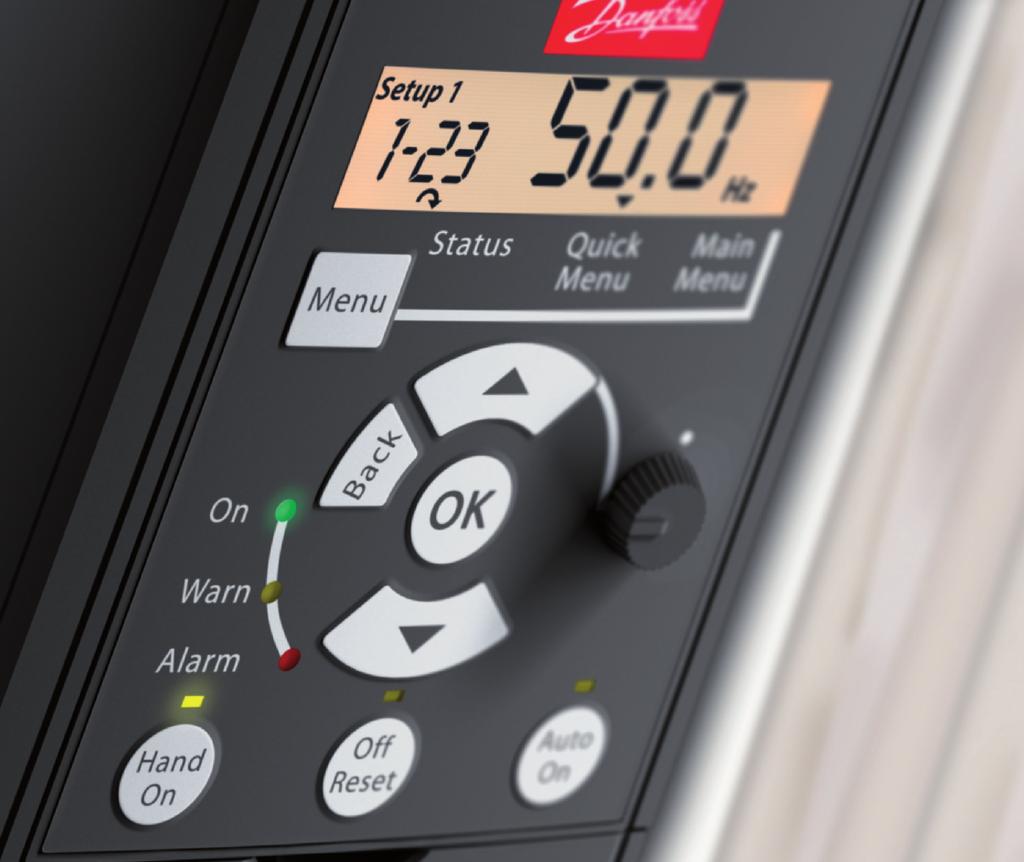
17 VLT Micro Drive FC 51 Operating Instructions 4. Programming 4. Programming 4.1. How to Programme Programming with MCT-10 The frequency converter can be programmed from a PC via RS485 com-port by installing the MCT-10 Set-up Software. This software can either be ordered using code number 130B1000 or downloaded from the Danfoss Web site: Business Area: Motion Controls. 4 Please refer to manual MG.10.RX.YY Programming with LCP 11 or LCP 12 The LCP is divided into four functional groups: 1. Numeric display. 2. Menu key. 3. Navigation keys. 4. Operation keys and indicator lights (LEDs). Illustration 4.2: LCP 11 without potentiometer Illustration 4.1: LCP 12 with potentiometer The display: A number of information can be read from the display. Set-up number shows the active set-up and the edit set-up. If the same set-up acts as both active and edit set-up, only that set-up number is shown (factory setting). When active and edit set-up differ, both numbers are shown in the display (Setup 12). The number flashing, indicates the edit set-up. Illustration 4.3: Indicating Set-up MG.02.A VLT is a registered Danfoss trademark 15
18 4. Programming VLT Micro Drive FC 51 Operating Instructions The small digits to the left are the selected parameter number. Illustration 4.4: Indicating selected par. no. 4 The large digits in the middle of the display show the value of the selected parameter. Illustration 4.5: Indicating value of selected par. The right side of the display shows the unit of the selected parameter. This can be either Hz, A, V, kw, HP, %, s or RPM. Illustration 4.6: Indicating unit of selected par. Motor direction is shown to the bottom left of the display - indicated by a small arrow pointing either clockwise or counterclockwise. Illustration 4.7: Indicating motor direction Use the [MENU] key to select one of the following menus: Status Menu: The Status Menu is either in Readout Mode or Hand on Mode. In Readout Mode the value of the currently selected readout parameter is shown in the display. In Hand on Mode the local LCP reference is displayed. Quick Menu: Displays Quick Menu parameters and their settings. Parameters in the Quick Menu can be accessed and edited from here. Most applications can be run by setting the parameters in the Quick Menus. Main Menu: Displays Main Menu parameters and their settings. All parameters can be accessed and edited here. A parameter overview is found later in this manual. Indicator lights: Green LED: Power is on the frequency converter. Yellow LED: Indicates a warning. Flashing red LED: Indicates an alarm. 16 MG.02.A VLT is a registered Danfoss trademark
19 VLT Micro Drive FC 51 Operating Instructions 4. Programming Navigation Keys: [Back]: For moving to the previous step or layer in the navigation structure. Arrows [ ] [ ]: For manoeuvring between parameter groups, parameters and within parameters. [OK]: For selecting a parameter and for accepting changes to parameter settings. Operation Keys: A yellow light above the operation keys indicates the active key. [Hand on]: Starts the motor and enables control of the frequency converter via the LCP. [Off/Reset]: The motor stops except in alarm mode. In that case the motor will be reset. [Auto on]: The frequency converter is controlled either via control terminals or serial communication. [Potentiometer] (LCP12): The potentiometer works in two ways depending on the mode in which the frequency converter is running. In Auto Mode the potentiometer acts as an extra programmable analog input. In Hand on Mode the potentiometer controls local reference Status Menu After power up the Status Menu is active. Use the [MENU] key to toggle between Status, Quick Menu and Main Menu. Arrows [ ] and [ ] toggles between the choices in each menu. The display indicates the status mode with a small arrow above Status. Illustration 4.8: Indicating Status mode 4.3. Quick Menu The Quick Menu gives easy access to the most frequently used parameters. 1. To enter the Quick Menu, press [MENU] key until indicator in display is placed above Quick Menu, then press [OK]. 2. Use [ ] [ ] to browse through the parameters in the Quick Menu. 3. Press [OK] to select a parameter. 4. Use [ ] [ ] to change the value of a parameter setting. 5. Press [OK] to accept the change. 6. To exit, press either [Back] twice to enter Status, or press [Menu] once to enter Main Menu Quick Menu Parameters Illustration 4.9: Indicating Quick Menu mode Quick Menu Parameters - Basic Settings QM1 Below are descriptions of all parameters found in the Quick Menu. = Factory setting Motor Power [kw]/[hp] (Pm.n) Option: Function: Enter motor power from nameplate data. Two sizes down, one size up from nominal VLT rating. [1] 0.09 kw/0.12 HP MG.02.A VLT is a registered Danfoss trademark 17
20 4. Programming VLT Micro Drive FC 51 Operating Instructions [2] 0.12 kw/0.16 HP [3] 0.18kW/0.25 HP [4] 0.25 kw/0.33 HP [5] 0.37kW/0.50 HP [6] 0.55 kw/0.75 HP [7] 0.75 kw/1.00 HP [8] 1.10 kw/1.50 HP [9] 1.50 kw/2.00 HP 4 [10] 2.20 kw/3.00 HP [11] 3.00 kw/4.00 HP [12] 3.70 kw/5.00 HP [13] 4.00 kw/5.40 HP [14] 5.50 kw/7.50 HP [15] 7.50 kw/10.0 HP [16] kw/15.00 HP NB! Changing this parameter affects par to 1-25, 1-30, 1-33 and Motor Voltage (U m.n) Range: Function: 230/400 V [ V] Enter motor voltage from nameplate data Motor Frequency (f m.n) Range: Function: 50 Hz* [ Hz] Enter motor frequency from nameplate data Motor Current (I m.n) Range: Function: M-type dependent* [ Enter motor current from nameplate data. A] 1-25 Motor Nominal Speed (n m.n) Range: Function: M-type Dependent* [ Enter motor nominal speed from nameplate data. RPM] 1-29 Automatic Motor Tuning (AMT) Option: Function: Use AMT to optimize motor performance. NB! This parameter cannot be changed while motor runs. 1. Stop VLT make sure motor is at standstill 2. Choose [2] Enable AMT 3. Apply start signal Via LCP: Press Hand On - Or in Remote On mode: Apply start signal on terminal MG.02.A VLT is a registered Danfoss trademark
21 VLT Micro Drive FC 51 Operating Instructions 4. Programming [0] * Off AMT function is disabled. [2] Enable AMT AMT function starts running. NB! To gain optimum tuning of frequency converter, run AMT on a cold motor Minimum Reference Range: Function: 0.00* [ ] Enter value for minimum reference. The sum of all internal and external references are clamped (limited) to the minimum reference value, par Maximum Reference Range: Function: Maximum Reference is adjustable in the range Minimum Reference * [ ] Enter value for Maximum Reference. The sum of all internal and external references are clamped (limited) to the maximum reference value, par Ramp1 Ramp-up Time Range: Function: 3.00 s* [ s ] Enter ramp-up time from 0 Hz to rated motor frequency (fm,n) set in par Choose a ramp-up time ensuring that torque limit is not exceeded, see par Ramp1 Ramp-down Time Range: Function: 3.00* [ s] Enter ramp down time from rated motor frequency (fm,n) in par to 0 Hz. Choose a ramp down time that does not cause over-voltage in inverter due to regenerative operation of motor. Furthermore, regenerative torque must not exceed limit set in par Quick Menu Parameters - PI Basic Settings QM2 The following is a brief description of the parameters for the PI Basic Settings. For a more detailed description, please see VLT Micro Drive Programming Guide, MG.02.CX.YY Configuration Mode Range: Function: [] Choose [3] Process Closed Loop 3-02 Min. Reference Range: Function: [ ] Sets limits for set-point and feedback Max. Reference Range: Function: [ ] Sets limits for set-point and feedback Preset Reference Range: Function: [ ] Preset [0] works as set-point Motor Speed Low Limit Range: Function: [ Hz] Lowest possible output frequency. MG.02.A VLT is a registered Danfoss trademark 19
22 4. Programming VLT Micro Drive FC 51 Operating Instructions 4-14 Motor Speed High Limit Range: Function: [ Hz] Highest possible output frequency. NB! Default 65 Hz should normally be reduced to Hz Terminal 60 Low Current Range: Function: [ ma] Normally set to 0 or 4 ma Terminal 60 High Current Range: Function: [ ma] Normally (default) set to 20 ma Terminal 60 Low Feedback Value Range: Function: [ ] Value corresponding to P setting Terminal 60 High Feedback Value Range: Function: [ ] Value corresponding to P setting Terminal 60 Filter Time Constant Range: Function: [ s] Filter for suppressing electrical noise Process CL Feedback Resource Range: Function: [] Choose [2] analog input Process PI Normal/Inverse Range: Function: [] Most PI controllers are Normal Process PI Anti Windup Range: Function: [] Leave Enabled normally Process PI Start Speed Range: Function: [ Hz] Choose expected normal running speed Process PI Proportional Gain Range: Function: [ ] Enter the P-factor Process PI Integral Time Range: Function: [ s] Enter the I-factor. 20 MG.02.A VLT is a registered Danfoss trademark
23 VLT Micro Drive FC 51 Operating Instructions 4. Programming 7-38 Process Feed Forward Factor Range: Function: [0-400%] Only applicable with changing set-points. 4 MG.02.A VLT is a registered Danfoss trademark 21
24 4. Programming VLT Micro Drive FC 51 Operating Instructions 4.5. Main Menu The Main Menu gives access to all parameters To enter the Main Menu, press [MENU] key until indicator in display is placed above Main Menu. 2. Use [ ] [ ] to browse through the parameter groups. 3. Press [OK] to select a parameter group. 4. Use [ ] [ ] to browse through the parameters in the specific group. 5. Press [OK] to select the parameter. 6. Use [ ] [ ] to set/change the parameter value. 7. Press [OK] to accept the value. 8. To exit, press either [Back] twice to enter Quick Menu, or press [Menu] once to enter Status. Illustration 4.10: Indicating Main Menu mode 22 MG.02.A VLT is a registered Danfoss trademark
25 VLT Micro Drive FC 51 Operating Instructions 5. Modbus RTU 5. Modbus RTU 5.1. Modbus RTU Overview Assumptions These operating instructions assume that the installed controller supports the interfaces in this document and that all the requirements stipulated in the controller, as well as the frequency converter, are strictly observed, along with all limitations therein What the User Should Already Know The Modbus RTU (Remote Terminal Unit) is designed to communicate with any controller that supports the interfaces defined in this document. It is assumed that the user has full knowledge of the capabilities and limitations of the controller Modbus RTU Overview Regardless of the type of physical communication networks, the Modbus RTU Overview describes the process a controller uses to request access to another device. This includes i.a. how it will respond to requests from another device, and how errors will be detected and reported. It also establishes a common format for the layout and contents of message fields. During communications over a Modbus RTU network, the protocol determines how each controller will learn its device address, recognise a message addressed to it, determine the kind of action to be taken, and extract any data or other information contained in the message. If a reply is required, the controller will construct the reply message and send it. Controllers communicate using a master-slave technique in which only one device (the master) can initiate transactions (called queries). The other devices (slaves) respond by supplying the requested data to the master, or by taking the action requested in the query. The master can address individual slaves, or can initiate a broadcast message to all slaves. Slaves return a message (called a response) to queries that are addressed to them individually. No responses are returned to broadcast queries from the master. The Modbus RTU protocol establishes the format for the master s query by placing into it the device (or broadcast) address, a function code defining the requested action, any data to be sent, and an error-checking field. The slave s response message is also constructed using Modbus protocol. It contains fields confirming the action taken, any data to be returned, and an error-checking field. If an error occurs in receipt of the message, or if the slave is unable to perform the requested action, the slave will construct an error message and send it in response, or a time-out will occur Frequency Converter with Modbus RTU The frequency converter communicates in Modbus RTU format over the built-in RS-485 interface. Modbus RTU provides access to the Control Word and Bus Reference of the frequency converter. The Control Word allows the Modbus master to control several important functions of the frequency converter: Start Stop of the frequency converter in various ways: Coast stop Quick stop DC Brake stop Normal (ramp) stop Reset after a fault trip Run at a variety of preset speeds Run in reverse Change the active set-up Control the frequency converter s built-in relay The Bus Reference is commonly used for speed control. It is also possible to access the parameters, read their values, and where possible, write values to them. This permits a range of control options, including controlling the setpoint of the frequency converter when its internal PI controller is used. MG.02.A VLT is a registered Danfoss trademark 23
26 5. Modbus RTU VLT Micro Drive FC 51 Operating Instructions 5.2. Modbus RTU Message Framing Structure Remote Terminal Unit The controllers are set up to communicate on the Modbus network using RTU (Remote Terminal Unit) mode, with each 8-bit byte in a message containing two 4-bit hexadecimal characters. The format for each byte is shown below. Start bit Data bit Stop/parity Stop 5 Coding system: Bits per byte: Error Check Field: 8-bit binary, hexadecimal 0-9, A-F. Two hexadecimal characters contained in each 8-bit field of the message. 1 start bit 8 data bits, least significant bit sent first Parity: 1 bit for even/odd parity is used; 1 or 2 stop bits if no parity is selected (see par. 8-33). Cyclical Redundancy Check (CRC) Modbus RTU Message Structure The transmitting device places a Modbus RTU message into a frame with a known beginning and ending point. This allows receiving devices to begin at the start of the message, read the address portion, determine which device is addressed (or all devices, if the message is broadcast), and to recognise when the message is completed. Partial messages are detected and errors set as a result - or timeouts occur. Characters for transmission must be in hexadecimal 00 to FF format in each field. The frequency converter continuously monitors the network bus, also during silent intervals. When the first field (the address field) is received, each frequency converter or device decodes it to determine which device is being addressed. Modbus RTU messages addressed to zero are broadcast messages. No response is permitted for boradcast messages. A typical message frame is shown below. Start Address Function Data CRC check End T1-T2-T3-T4 1 byte 1 byte N x 1 byte 2 bytes T1-T2-T3-T4 Table 5.1: Typical Modbus RTU Message Structure Start/Stop Field Messages start with a silent period of at least 3.5 character intervals. This is implemented as a multiple of character intervals at the selected network baud rate (shown as Start T1-T2-T3-T4). The first field to be transmitted is the device address. Following the last transmitted character, a similar period of at least 3.5 character intervals marks the end of the message. A new message can begin after this period. The entire message frame must be transmitted as a continuous stream. If a silent period of more than 1.5 character intervals occurs before completion of the frame, the receiving device flushes the incomplete message and assumes that the next byte will be the address field of a new message. Similarly, if a new message begins prior to 3.5 character intervals after a previous message, the receiving device will ignore both messages. This will cause a timeout (no response from the slave) Address Field The address field of a message frame contains 1 byte. Valid slave device addresses are in the range of decimal. The individual slave devices are assigned addresses in the range of (0 is reserved for broadcast mode, which all slaves recognise). A master addresses a slave by placing the slave address in the address field of the message. 24 MG.02.A VLT is a registered Danfoss trademark
27 VLT Micro Drive FC 51 Operating Instructions 5. Modbus RTU When the slave sends its response, it places its own address in this address field to let the master know which slave is responding Function Field The function field of a message frame contains 1 byte. Function fields are used to send messages between master and slave. When a message is sent from a master to a slave device, the function code field tells the slave what kind of action to perform. When the slave responds to the master, it uses the function code field to indicate either a normal (error-free) response, or that some kind of error occurred (called an exception response). For a normal response, the slave simply echoes the original function code. For an exception response, the slave returns a code that is equivalent to the original code with its most significant bit set to logic 1. In addition, the slave places a unique code into the data field of the response message. This tells the master what kind of error occurred, or the reason for the exception. Please also refer to the sections Function Codes Supported by Modbus RTU and Exception Codes Data Field The data field is constructed using sets of two hexidecimal digits in the range of 00 to FF hexidecimal. These are made up of one RTU character. The data field of messages sent from a master to a slave device contains additional information which the slave must use to take the action defined by the function code. This can include items such as addresses of coils or registers, the quantity of items to be handled. and the count of actual data bytes in the field CRC Check Field Messages include an error-checking field, operating on the basis of a Cyclical Redundancy Check (CRC) method. The CRC field checks the content of the entire message. It is applied regardless of any parity check method used for the individual characters of the message. The CRC value is calculated by the transmitting device, which appends the CRC as the last field in the message. The receiving device recalculates a CRC during receipt of the message and compares the calculated value to the actual value received in the CRC field. If the two values are unequal, a bus timeout occurs. The error-checking field contains a 16-bit binary value implemented as two 8-bit bytes. When this is done, the low-order byte of the field is appended first, followed by the high-order byte. The CRC high-order byte is the last byte sent in the message Coil/Register Addressing In Modbus, all data are organised in coils and holding registers. Coils hold a single bit, whereas holding registers hold a 2-byte word (i.e. 16 bits). All data addresses in Modbus messages are referenced to zero. The first occurrence of a data item is addressed as item number zero. Example: The coil known as coil 1 in programmable controller is addressed as coil 0000 in the data address field of a Modbus message. Coil 127 decimal is addressed as coil 007EHEX (126 decimal). Holding register is addressed as register 0000 in the data address field of the message. The function code field already specifies a holding register operation. Therefore, the 4XXXX reference is implicit. Holding register is addressed as register 006BHEX (107 decimal). MG.02.A VLT is a registered Danfoss trademark 25
28 5. Modbus RTU VLT Micro Drive FC 51 Operating Instructions 5 Coil number Description Signal direction 1-16 Frequency converter control word (see table below) Master to slave Frequency converter speed or set-point reference Range 0x0-0xFFFF (-200%... ~ 200%) Master to slave Frequency converter status word (see table below) Slave to master Open loop mode: Frequency converter output frequency Slave to master Closed loop mode: Frequency converter feedback signal 65 Parameter write control (master to slave) Master to slave 0 = Parameter changes are written to the RAM of the frequency converter 1 = Parameter changes are written to the RAM and EEPROM of the frequency converter Reserved Coil Preset reference LSB 02 Preset reference MSB 03 DC brake No DC brake 04 Coast stop No coast stop 05 Quick stop No quick stop 06 Freeze outp No freeze outp 07 Ramp stop Start 08 No function Reset 09 No jog Jog 10 Ramp 1 Ramp 2 11 Data not valid Data valid 12 Relay 1 off Relay 1 on 13 Not used Not used 14 Setup 1 Setup 2 15 Not used Not used 16 No reversing Reversing Frequency converter control word (FC profile) Coil Control not ready Control ready 34 Unit not ready Unit ready 35 Coasted Not coasted 36 Error, tripped 37 Error, no trip 38 Not used Not used 39 Error, trip locked 40 No warning Warning 41 Not on reference On reference 42 Hand mode Auto mode 43 Out of freq. range In frequency range 44 Not running Running 45 No res. brake fault Resistor brake fault 46 No voltage warning Voltage warning 47 Not in current limit Current limit 48 No thermal warning Thermal warning Frequency converter status word (FC profile) Register number Description Reserved Last error code from an FC data object interface Reserved Parameter index* parameter group (parameters 001 through 099) parameter group (parameters 100 through 199) parameter group (parameters 200 through 299) parameter group (parameters 300 through 399) parameter group (parameters 400 through 499) parameter group (parameters 4900 through 4999) Input data: Frequency converter control word register (CTW) Input data: Bus reference register (REF) Output data: Frequency converter status word register (STW) Output data: Frequency converter main actual value register (MAV). Table 5.2: Holding Registers * Used to specify the index number to be used when accessing an indexed parameter 26 MG.02.A VLT is a registered Danfoss trademark
29 VLT Micro Drive FC 51 Operating Instructions 5. Modbus RTU 5.3. How to Control FC 51 This section describes codes which can be used in the function and data fields of a Modbus RTU message. For a complete description of all the message fields please refer to the section Modbus RTU Message Framing Structure Function Codes Supported by Modbus RTU Modbus RTU supports use of the following function codes in the function field of a message: Function Read coils Read holding registers Write single coil Write single register Write multiple coils Write multiple registers Get comm. event counter Report slave ID Function Code 1 hex 3 hex 5 hex 6 hex F hex 10 hex B hex 11 hex 5 Function Function code Sub-function code Sub-function Diagnostics 8 1 Restart communication 2 Return diagnostic register 10 Clear counters and diagnostic register 11 Return bus message count 12 Return bus communication error count 13 Return bus exception error count 14 Return slave message count Exception and Error Codes In the event of an error, the following exception codes may appear in the data field of a response message. For a full explanation of the structure of an exception (i.e. error) response, please refer to Function Field in section Modbus RTU Message Framing Structure. MODBUS Exception Codes Code Name Meaning 1 Illegal function The function code received in the query is not an allowable action for the server (or slave). This may be because the function code is only applicable to newer devices, and was not implemented in the unit selected. It could also indicate that the server (or slave) is in the wrong state to process a request of this type, for example it is not configured and is being asked to return register values. 2 Illegal data address The data address received in the query is not an allowable address for the server (or slave). More specifically, the combination of reference number and transfer length is invalid. For a controller with 100 registers, a register with offset 96 and length 4 would succeed, a request with offset 96 and length 5 will generate exception Illegal data value A value contained in the query data field is not an allowable value for server (or slave). This indicates a fault in the structure of the remainder of a complex request, such as an incorrect implied length. It specifically does NOT mean that a data item submitted for storage in a register has a value outside the expectation of the application program, since the MODBUS protocol is unaware of the significance of any particular value of any particular register. 4 Slave device failure An unrecoverable error occurred while the server (or slave) was attempting to perform the requested action In case of an exception code 4 while accessing parameter values in the drive, detailed information about the latest exception can be read from the drives Holding Register This register may contain one of the following, detailed error codes regarding the latest occurring MODBUS Exception. MG.02.A VLT is a registered Danfoss trademark 27
30 5. Modbus RTU VLT Micro Drive FC 51 Operating Instructions Error code in holding register 0007 Description 00 The parameter number does not exist 01 There is no write access to the parameter 02 The data value exceeds the parameter limits 03 The sub-index in use does not exist 05 The data type does not match the parameter called 17 Data change in the parameter called is not possible in the present mode 18 Other error 130 There is no bus access to the parameter called 5.4. How to Access Parameters Parameter Handling The PNU (Parameter Number) is translated from the register address contained in the Modbus read or write message. The parameter number is translated to Modbus register address as (10 x parameter number -1)DECIMAL Storage of Data The Coil 65 decimal determines whether data written to the frequency converter are stored in EEPROM and RAM (coil 65 = 1) or only in RAM (coil 65 = 0) IND The array index is set in Holding Register 9 and used when accessing array parameters Text Blocks Parameters stored as text strings are accessed in the same way as the other parameters. The maximum text block size is 20 characters. If a read request for a parameters is for more characters than the parameter stores, the response is truncated. If the read request for a parameter is for fewer characters than the parameter stores, the response is space filled Conversion Factor The different attributes for each parameter can be seen in the section on factory settings. Since a parameter value can only be transferred as a whole number, a conversion factor must be used to transfer decimals. Please refer to the section Conversion Index Parameter Values Standard Data Type Standard data types are int16, int32, uint8, uint16 and uint32. They are stored as 4x registers ( FFFF). The parameters are read using function 03HEX Read Holding Registers. Parameters are writtein using the function 6HEX Preset Single Register for 1 register (16 bits), and the function 10HEX Preset Multiple Registers for 2 registers (32 bits). Readable sizes range from 1 register (16 bits) up to 10 registers (20 characters). Non Standard Data Types Non standard data types are text strings and are stored as 4x registers ( FFFF). The parameters are read using function 03 HEX Read Holding Registers and written using function 10 HEX Preset Multiple Registers. Readable sizes range from 1 register (2 characters) up to 10 registers (20 characters). 28 MG.02.A VLT is a registered Danfoss trademark
31 VLT Micro Drive FC 51 Operating Instructions 5. Modbus RTU 5.5. Examples The following examples illustrate various Modbus RTU commands. If an error occurs, please refer to the Exception Codes section Read Coil Status (01HEX) Description This function reads the ON/OFF status of discrete outputs (coils) in the frequency converter. Broadcast is never supported for reads. Query The query messages specifies the staring coil and quantity of coils to be read. Coil addresses start at zero, i.e. coil 33 is addressed as 32. Example of a request to read coils (Status Word) from slave device 01: Field Name Example (HEX) Slave address 01 (frequency converter address) Function 01 (read address) Starting Address HI 00 Starting Address LO 20 (32 decimal) No. of Points HI 00 No. of Points LO 10 (16 decimal) Error Check (CRC) - 5 Response The coil status in the response message is packed as one coil per bit of the data field. Status is indicated as: 1 = ON; 0 = OFF. The LSB of the first data byte contains the coil addressed in the query. The other coils follow toward the high order end of this byte, and from low order to high order in subsequent bytes. If the returned coil quantity is not a multiple of eight, the remaining bits in the final data byte will padded with zeros (toward the high order and of the byte). The Byte Count field specifies the number of complete bytes of data. Field Name Example (HEX) Slave address 01 (frequency converter address) Function 01 (read coils) Byte count 02 (2 bytes of data) Data (Coils 40-33) 07 Data (Coils 48-41) 06 (STW = 0607hex) Error Check (CRC) Force/Write Single Coil (05HEX) Description This function forces a coil to either ON or OFF. When broadcast the function forces the same coil references in all attached slaves. Query The query message specifies the coil 65 (parameter write control) to be forced. Coil addresses start at zero, i.e. coil 65 is addressed as 64. Force Data = 00 00HEX (OFF) or FF 00HEX (ON). Field Name Example (HEX) Slave address 01 (frequency converter address) Function 05 (write single coil) Coil Address HI 00 Coil Address LO 40 (coil no. 65) Force Data HI FF Force Data LO 00 (FF 00 = ON) Error Check (CRC) - MG.02.A VLT is a registered Danfoss trademark 29
32 5. Modbus RTU VLT Micro Drive FC 51 Operating Instructions Response The normal response is an echo of the query, returned after the coil state has been forced. Field Name Example (HEX) Slave address 01 Function 05 Force Data HI FF Force Data LO 00 Quantity of coils HI 00 Quantity of coils LO 01 Error Check (CRC) Force/Write Multiple Coils (0FHEX) 5 Description This function forces each coil in a sequence of coils to either ON or OFF. When broadcast the function forces the same coil references in all attached slaves. Query The query message specifies the coils 17 to 32 (speed set-point) to be forced. Coil addresses start at zero, i.e. coil 17 is addressed as 16. Field Name Example (HEX) Slave address 01 (frequency converter address) Function 0F (write multiple coil) Coil Address HI 00 Coil Address LO 10 (coil address 17) Quantity of coils HI 00 Quantity of coils LO 10 (16 coils) Byte count 02 Force Data HI (coils 8-1) 20 Force Data LO (coils 10-9) 00 (ref. = 2000hex) Error Check (CRC) - Response The normal response returns the slave address, function code, starting address, and quantity of coils forced. Field Name Example (HEX) Slave address 01 (frequency converter address) Function 0F (write multiple coils) Coil Address HI 00 Coil Address LO 10 (coil address 17) Quantity of coils HI 00 Quantity of coils LO 10 (16 coils) Error Check (CRC) - 30 MG.02.A VLT is a registered Danfoss trademark
33 VLT Micro Drive FC 51 Operating Instructions 5. Modbus RTU Read Holding Registers (03HEX) Description This function reads the content of holding registers in the slave. Query The query message specifies the starting register and quantity to be read. Register addresses start at zero, i.e. registers 1-4 are addressed as 0-3. Example Read PNU 342 which is mapped to register 0x0D5B(RegAdr = 342 x 10-1) Field Name Example (HEX) Slave address 01 Function 03 Starting Address HI 0D Starting Address LO 5B No. of Points HI 00 No. of Points LO 02 Error Check (CRC) - 5 Table 5.3: Request frame Response The register data in the response message are packed as two bytes per register, with the binary contents right justified within each byte. For each register, the first byte contains the high order bits and the second contains the low order bits. Field Name Example (HEX) Slave address 01 Function 03 Data HI (Register 3419) 00 Data LO (Register 3419) 00 Data HI (Register 3420) 00 Data LO (Register 3420) 03 Error Check (CRC) - Table 5.4: Normal response frame Preset Single Register (06HEX) Description This function presets a value into a single holding register. Query The query message specifies the register reference to be preset. Register addresses start at zero, i.e. register 1 is addressed as 0. Example Write 1 to PNU3 which is mapped to register 0x001D (3 x 10-1 = 29 = 001DHex) Field Name Example (HEX) Slave address 01 Function 06 Starting Address HI 00 Starting Address LO 1D No. of Points HI 00 No. of Points LO 01 Error Check (CRC) - Table 5.5: Request frame MG.02.A VLT is a registered Danfoss trademark 31
AF-60 LP TM Micro Drive
 GE Consumer & Industrial Electrical Distribution AF-60 LP TM Micro Drive Operating Instructions Contents 1 Safety 5 Safety Instructions 5 Software Version and Approvals 6 General Warning 7 Avoid unintended
Modbus RTU Option Card for VLT 5000/6000 Adjustable Frequency Drive
 Modbus RTU Option Card for VLT 5000/6000 Adjustable Frequency Drive VLT is a registered Danfoss trade mark MG.10.P2.22 1 Rotating shafts and electrical equipment can be hazardous. Perform all electrical
Supported Modbus RTU Function Codes... 26
 å Contents Overview... 5 Introduction... 5 About This Manual... 5 Assumptions... 5 What You Should Already Know... 5 Modbus RTU Overview... 5 VLT 2800 and VLT 6000 with Modbus RTU... 6 Installation and
Instruction Manual. Modbus RTU VLT 5000 VLT 6000 HVAC
 Instruction Manual Modbus RTU VLT 5000 VLT 6000 HVAC Modbus RTU Option Card VLT 6000 Adjustable Frequency Drive Instruction Manual 23-6130-00 Revision B 02/03 Rotating shafts and electrical equipment can
Operating Instructions. Modbus RTU VLT 2800 VLT 6000 VLT 8000
 Operating Instructions Modbus RTU VLT 2800 VLT 6000 VLT 8000 Contents Overview... 6 Introduction... 6 About This Manual... 6 Assumptions... 6 What You Should Already Know... 6 Modbus RTU Overview... 6
FREQUENCY CONVERTER FC101 (QUICK GUIDE)
") FREQUENCY CONVERTER FC101 (QUICK GUIDE) INSTALLATION AND MAINTENANCE Content Page Safety instructions 2 IT system 3x230VAC 2 Connections 3 Control unit (LCP) 4 Manual operation 4 Reverse the direction
FREQUENCY CONVERTER FC101 (QUICK GUIDE) INSTALLATION AND MAINTENANCE Content Page Safety instructions 2 IT system 3x230VAC 2 Connections 3 Control unit (LCP) 4 Manual operation 4 Reverse the direction
FREQUENCY CONVERTER FC102 (QUICK GUIDE)
") FREQUENCY CONVERTER FC102 (QUICK GUIDE) INSTALLATION AND MAINTENANCE Content Page Safety instructions 2 IT system 3x230VAC 2 Connections 3 Control unit (LCP) 4 Manual operation 4 Reverse the direction
FREQUENCY CONVERTER FC102 (QUICK GUIDE) INSTALLATION AND MAINTENANCE Content Page Safety instructions 2 IT system 3x230VAC 2 Connections 3 Control unit (LCP) 4 Manual operation 4 Reverse the direction
FLÄKTGROUP OFFERS A WIDE RANGE OF PER- MANENT MAGNET MOTORS (PM) AND FREQUENCY CONVERTERS FOR PLUG FANS. POWER RANGE IS FROM 0,8 KW TO 15 KW.
 AND FREQUENCY CONVERTERS FOR PLUG FANS. POWER RANGE IS FROM 0,8 KW TO 15 KW.") CENTRIFLOW PUR 3D (A, PLUG B, C, D) FAN GMPM FC101 AND SLIDE IN FREQUENCY ROTOR CASSETTE CONVERTER QUICK GUIDE FLÄKTGROUP OFFERS A WIDE RANGE OF PER- MANENT MAGNET MOTORS (PM) AND FREQUENCY CONVERTERS
CENTRIFLOW PUR 3D (A, PLUG B, C, D) FAN GMPM FC101 AND SLIDE IN FREQUENCY ROTOR CASSETTE CONVERTER QUICK GUIDE FLÄKTGROUP OFFERS A WIDE RANGE OF PER- MANENT MAGNET MOTORS (PM) AND FREQUENCY CONVERTERS
AF-60 LP TM Micro Drive. Programming Guide
 GE AF-60 LP TM Micro Drive Programming Guide Contents Contents 1 Safety 1-1 1.1.1 High Voltage Warning 1-1 1.1.2 Safety Instructions 1-1 1.1.3 Software Version and Approvals 1-1 1.1.4 General Warning 1-1
Operating Instructions Extended Cascade Controller MCO 101
 Operating Instructions Extended Cascade Controller MCO 101 VLT AQUA Drive FC 200 Extended Cascade Controller Option Contents Contents 1. Safety and precautions 3 Safety Instructions 3 Avoid unintended
Safety Instructions 1-1 Avoid unintended Start General Description 2-2
 Contents Contents 1 Safety and precautions 1-1 Safety Instructions 1-1 Avoid unintended Start. 1-1 2 Introduction 2-1 General Description 2-2 3 Supported Configuration 3-1 Introduction 3-1 Fixed-speed
Quick Guide. VLT Micro Drive FC 51
 Quick Guide VLT Micro Drive FC 5 Quick Guide for VLT Micro FC 5. Quick Guide. Quick Guide... Available Literature NB! This quick guide contains the basic information necessary for installing and running
MAKING MODERN LIVING POSSIBLE. Quick Guide VLT HVAC Basic Drive
 MAKING MODERN LIVING POSSIBLE Quick Guide VLT HVAC Basic Drive Contents Contents Quick Guide 2. Safety 2.. Warnings 2..2 Safety Instructions 2.2 Introduction 2.2. Available Literature 2.2.2 Approvals 2.2.3
MAKING MODERN LIVING POSSIBLE. Quick Guide VLT Micro Drive FC 51
 MAKING MODERN LIVING POSSIBLE Quick Guide VLT Micro Drive FC 5 Quick Guide for VLT Micro FC 5 Quick Guide Quick Guide. Safety.. Warnings High Voltage Warning: The voltage of the adjustable frequency drive
It is the installer's responsibility to follow all instructions in this manual and to follow correct electrical practice.
 MCD Modbus Module Instructions Important User Information INSTALLATION INSTRUCTIONS: MCD MODBUS MODULE Order Code: 175G9000 1. Important User Information Observe all necessary safety precautions when controlling
VLT 8000 AQUA. Installation. Mechanical installation
 Mechanical installation Please pay attention to the requirements that apply to integration and field mounting kit, see the below list. The information given in the list must be observed to avoid serious
1 Extended and Advanced Cascade Controller Option 3
 VLT Operating Instructions Contents Contents Extended and Advanced Cascade Controller 3 How to read these Operating Instructions 3 High Voltage Warning 3 Safety Instructions 3 Avoid unintended Start 3
AF-600 FP TM Fan & Pump Drive. (230V to 60HP, 460/575V to 125HP Operating Instructions
 GE AF-600 FP TM Fan & Pump Drive (230V to 60HP, 460/575V to 125HP Operating Instructions Safety Safety WARNING HIGH VOLTAGE! Frequency converters contain high voltage when connected to AC mains input power.
Metasys N2 Instruction Manual VLT Adjustable Frequency Drive. 12/ Revision B
 Metasys N2 Instruction Manual VLT 6000 Adjustable Frequency Drive 12/99-6110-00 Revision B 2 Table of Contents Overview Page Introduction... 5 About this Manual... 5 References... 5 Instructions Abbreviations
Golander Peristaltic Pump MODBUS Communication Instruction
 Golander Peristaltic Pump MODBUS Communication Instruction 1 Introduction... 1 2 Modbus Protocol... 2 2.1 Modbus Protocol Model... 2 2.2 Byte Format... 2 2.3 MODBUS Message Timing... 2 2.4 Field... 3 2.5
INTELLIS. Modbus Direct Network Monitor
 INTELLIS Modbus Direct Network Monitor System Installation and Operation Manual Phone: (201) 794-7650 Fax: (201)794-0913 Chapter 1 Modbus Protocol Revision History Revision 1.0 30 April, 2002 Initial Version
1 How to Read these Operating Instructions 3. 3 Introduction to MCF 106 A/ B in C Option Adaptor 7
 MCF 106 A/ in C Option Adaptor Instruction Contents Contents 1 How to Read these Operating Instructions 3 Available Literature for VLT AutomationDrive FC 300 3 Approvals 4 Symbols 4 Abbreviations 4 2 Safety
MAKING MODERN LIVING POSSIBLE. Quick Guide. VLT HVAC Basic Drive Cascade Control *MG18F102*
 MAKING MODERN LIVING POSSIBLE www.danfoss.com/drives Quick Guide VLT HVAC Basic Drive Cascade Control 30R0265 MG8F02 *MG8F02* Rev. 20-03-22 Contents Contents Quick Guide 2. Safety 2.. Warnings 2..2 Safety
VLT Micro Drive. Ready Set Go!
 Despite its compact size and ease of installation, the VLT Micro Drive can deliver exceptional performance even in complex applications. 1 Well protected IP20 enclosure with NEMA/UL Type 1 optional; no
ATV12P037F1 variable speed drive ATV kW hp V - 1ph - on base plate
 Characteristics variable speed drive ATV12-0.37kW - 0.55hp - 100..120V - 1ph - on base plate Complementary Main Range of product Altivar 12 Product or component type Product destination Product specific
User Guide VLT Parallel Drive Modules
 ENGINEERING TOMORROW User Guide VLT Parallel Drive Modules 250 1200 kw vlt-drives.danfoss.com Contents User Guide Contents 1 Introduction 4 1.1 Purpose of the Manual 4 1.2 Additional Resources 4 1.3 Manual
ATV12H018M2 variable speed drive ATV kW hp V - 1ph
 Characteristics variable speed drive ATV12-0.18kW - 0.25hp - 200..240V - 1ph Complementary Main Range of product Altivar 12 Product or component type Product destination Product specific application Assembly
ATV12HU22M3 variable speed drive ATV12-2.2kW - 3hp V - 3ph - with heat sink
 Characteristics variable speed drive ATV12-2.2kW - 3hp - 200..240V - 3ph - with heat sink Main Range of product Altivar 12 Product or component type Product destination Product specific application Assembly
ATV12P075M3 variable speed drive ATV kW - 1hp V - 3ph - on base plate
 Characteristics variable speed drive ATV12-0.75kW - 1hp - 200..240V - 3ph - on base plate Main Range of product Altivar 12 Product or component type Product destination Product specific application Assembly
Quick Guide VLT Micro Drive FC 51
 ENGINEERING TOMORROW Quick Guide VLT Micro Drive FC 51 vlt-drives.danfoss.com Contents Quick Guide Contents 1 Quick Guide 2 1.1 Safety 2 1.2 Introduction 3 1.2.1 Purpose of the Manual 3 1.2.2 Additional
Operating instructions. Standstill monitor A / / 2011
 Operating instructions Standstill monitor A300 UK 1 2 3 4 5 6 7 8 7390337 / 01 02 / 2011 1 2 3 4 5 6 7 8 switchpoint min max pulse/min power Made in Germany ifm electronic gmbh D 45127 Essen func. I II
Quick Guide VLT Micro Drive FC 51
 MAKING MODERN LIVING POSSIBLE Quick Guide VLT Micro Drive FC 51 www.danfoss.com/drives Contents Quick Guide Contents 1 Quick Guide 2 1.1 Safety 2 1.2 Introduction 3 1.2.1 Purpose of the Manual 3 1.2.2
ATV310HU30N4E variable speed drive ATV310-3 kw - 4 hp V - 3 phase
 Characteristics variable speed drive ATV310-3 kw - 4 hp - 380...460 V - 3 phase Complementary Product destination Main Range of product Altivar Easy 310 Product or component type Product specific application
ATV310H075N4E variable speed drive ATV kw - 1 hp V - 3 phase
 Characteristics variable speed drive ATV310-0.75 kw - 1 hp - 380...460 V - 3 phase Main Range of product Altivar Easy 310 Product or component type Product specific application Assembly style Device short
Copyright: December 2017 Nidec Issue: E
 General Information The manufacturer accepts no liability for any consequences resulting from inappropriate, negligent or incorrect installation or adjustment of the optional parameters of the equipment
User Guide IM/C250 MOD_3. Modbus (RTU) Communications Option C250 and V250
 Communications Option C250 and V250") User Guide IM/C250 MOD_3 Modbus (RTU) Communications Option C250 and V250 Electrical Safety This instrument complies with the requirements of CEI/IEC 61010-1:2001-2 "Safety requirements for electrical
User Guide IM/C250 MOD_3 Modbus (RTU) Communications Option C250 and V250 Electrical Safety This instrument complies with the requirements of CEI/IEC 61010-1:2001-2 "Safety requirements for electrical
Instruction AKD LonWorks ADAP-KOOL AK-LON
 Instruction AKD LonWorks ADAP-KOOL AK-LON ADAP-KOOL AKD-LonWorks 1 Copyright 1Copyright 1.1 Copyright 1 1.1.1 Copyright, Limitation of Liability and Revision Rights This publication contains information
ATV12H075M3 variable speed drive ATV kW - 1hp V - 3ph - with heat sink
 Product datasheet Characteristics ATV12H075M3 variable speed drive ATV12-0.75kW - 1hp - 200..240V - 3ph - with heat sink Complementary Main Range of product Altivar 12 Product or component type Product
Installation Guide VLT PROFIBUS DP MCA 101
 MAKING MODERN LIVING POSSIBLE Installation Guide VLT PROFIBUS DP MCA 101 VLT Frequency Converter FC 102 FC 103 FC 202 FC 301/302 FCP 106 FCM 106 vlt-drives.danfoss.com Contents Installation Guide Contents
MAKING MODERN LIVING POSSIBLE. Quick Guide. VLT Micro Drive
 MAKING MODERN LIVING POSSIBLE VLT Micro Drive 1 VLT Micro Drive 1 1 1.1 Safety 1.1.1 Warnings WARNING HIGH VOLTAGE! Adjustable frequency drives contain high voltage when connected to AC line power. Installation,
Operating instructions. Switching amplifier DN0210 DN / / 2015
 Operating instructions Switching amplifier DN0210 DN0220 UK 80011079 / 00 01 / 2015 Contents 1 Preliminary note...4 1.1 Symbols used...4 1.2 Warning signs used...4 2 Safety instructions...5 2.1 General...5
VLT Line Filter MCC 107 EMC Filter Series VLT Midi Drive FC 280 (K1 K3)
") These instructions provide technical and installation information for the MCC 107 EMC filter series. Only Danfoss qualified personnel is allowed to install this equipment. The personnel must be familiar
These instructions provide technical and installation information for the MCC 107 EMC filter series. Only Danfoss qualified personnel is allowed to install this equipment. The personnel must be familiar
Unidrive M200, M201 (Frame 1 to 4) Quick Start Guide
 Quick Start Guide") This guide is intended to provide basic information required in order to set-up a drive to run a motor. Please refer to the Unidrive M200 / M20 User Guide which is available to download from www.controltechniques.com/user
This guide is intended to provide basic information required in order to set-up a drive to run a motor. Please refer to the Unidrive M200 / M20 User Guide which is available to download from www.controltechniques.com/user
Operating Guide MODBUS (RTU) Communications Option IM/L150 MOD_2. Level Indicator L150 and L160
 Communications Option IM/L150 MOD_2. Level Indicator L150 and L160") Operating Guide MODBUS (RTU) Communications Option IM/L150 MOD_2 Level Indicator L150 and L160 Electrical Safety This equipment complies with the requirements of CEI/IEC 61010-1:2001-2 "Safety requirements
Operating Guide MODBUS (RTU) Communications Option IM/L150 MOD_2 Level Indicator L150 and L160 Electrical Safety This equipment complies with the requirements of CEI/IEC 61010-1:2001-2 "Safety requirements
Instructions. Modbus RTU Card (WSIQ-COM-MB)
") Instructions (WSIQ-COM-MB) Contents 1 Warnings... 2 2 Important User Information... 2 3 Installation... 2 4 Operation... 3 5... 4 6 Specifications... 15 Product Compatibility The is suitable for use with
Instructions (WSIQ-COM-MB) Contents 1 Warnings... 2 2 Important User Information... 2 3 Installation... 2 4 Operation... 3 5... 4 6 Specifications... 15 Product Compatibility The is suitable for use with
AF-600 FP TM Fan and Pump Drive. (460V/575V 150HP and above) Operating Instructions
 Operating Instructions") GE AF-600 FP TM Fan and Pump Drive (460V/575V 150HP and above) Operating Instructions Contents Contents 1 How to Read these Operating Instructions 4 1.1.1 Copyright, Limitation of Liability and Revision
GE AF-600 FP TM Fan and Pump Drive (460V/575V 150HP and above) Operating Instructions Contents Contents 1 How to Read these Operating Instructions 4 1.1.1 Copyright, Limitation of Liability and Revision
Unidrive M400 (Frame 1 to 4) Quick Start Guide
 Quick Start Guide") This guide is intended to provide basic information required in order to set-up a drive to run a motor. For more detailed installation information, please refer to the Unidrive M400 User Guide which is
This guide is intended to provide basic information required in order to set-up a drive to run a motor. For more detailed installation information, please refer to the Unidrive M400 User Guide which is
Operating instructions. Speed monitor D / / 2014
 Operating instructions Speed monitor D200 80005257 / 00 05 / 2014 Contents 1 Preliminary note...4 1.1 Symbols used...4 1.2 Warning signs used...4 2 Safety instructions...5 2.1 General...5 2.2 Target group...5
Line reactors SINAMICS. SINAMICS G130 Line reactors. Safety information 1. General. Mechanical installation 3. Electrical installation
 Safety information 1 General 2 SINAMICS SINAMICS G130 Mechanical installation 3 Electrical installation 4 Technical specifications 5 Operating Instructions Control version V4.7 04/2014 A5E00331462A Legal
RAD-DO8-IFS. I/O extension module, eight digital transistor outputs. Data sheet. 1 Description
 I/O extension module, eight digital transistor outputs Data sheet 105364_en_00 PHOENIX CONTACT 2013-03-26 1 Description The I/O extension module can be used in conjunction with Radioline wireless modules
E2 Modbus RTU Register Map Revision History Version Comments Author Date 1.02 Previous version PAE 11/06/ Revised to new format PAE 09/03/09
 Application Note Title AN-ODE-01 E2 Modbus RTU Register Map Revision History Version Comments Author Date 1.02 Previous version PAE 11/06/08 1.03 Revised to new format PAE 09/03/09 General This document
VLT 2800 DRIVE SPECIFICATIONS
 VLT 2800 DRIVE SPECIFICATIONS Drive Input Power Input voltage 3 phase... 200 through 240, or 380 through 460; 3-phase all ratings 200 through 240, 1-phase through 2 HP Input voltage range for full output...
User guide. SRC Pumpdrive with SmartRun functionality, dedicated for waste water pump station
 User guide SRC 311 - Pumpdrive with SmartRun functionality, dedicated for waste water pump station Table of Contents Table of Contents Introduction and Safety...2 SRC 311...2 Electromagnetic Compatibility...4
ATV32HU11M2437 variable speed drive ATV32-1.1kW 200V - 1P - Bluetooth built-in - w heat sink
 Characteristics variable speed drive ATV32-1.1kW 200V - 1P - Bluetooth built-in - w heat sink Main Range of product Altivar 32 Product or component type Product destination Product specific application
INGERSOLL RAND Fixed Speed/Variable Speed Conversion COMMISSIONING AND OPERATION MANUAL
 INGERSOLL RAND Fixed Speed/Variable Speed Conversion COMMISSIONING AND OPERATION MANUAL Before installing or starting this unit for the first time, this manual should be studied carefully to obtain a working
User Guide Supplement Modbus TM Serial Data Communications Option IM/C100 MOD_6. /8 DIN Process Indicators and Controllers C100, C150, C160 and V100
 User Guide Supplement Modbus TM Serial Data Communications Option IM/C100 MOD_6 1 /8 DIN Process Indicators and Controllers C100, C150, C160 and V100 Electrical Safety This equipment complies with the
RAD-DOR4-IFS. I/O extension module, 4 digital relay outputs. INTERFACE Data sheet. 1 Description
 I/O extension module, 4 digital relay outputs INTERFACE Data sheet 104834_en_01 PHOENIX CONTACT 2013-01-21 1 Description The RAD-DOR4-IFS I/O extension module can be used in conjunction with Radioline
Rhino Redundancy Module PSM24-REM360S. Operating Instructions
 Rhino Redundancy Module PSM4-REM360S Operating Instructions RHINO REDUNDANCY MODULE PSM4-REM360S Description With this module and two power supplies of the PSM series (78, 90, 56, 80 and 360 watt models),
User Guide. IP20 & IP66 (NEMA 4X) AC Variable Speed Drive. Installation and Operating Instructions. 1 Quick Start Up kW (0.
 AC Variable Speed Drive. Installation and Operating Instructions. 1 Quick Start Up kW (0.") 1 Quick Start Up User Guide IP20 & IP66 (NEMA 4X) AC Variable Speed Drive 0.37 22kW (0.5 30HP) 110 480V Installation and Operating Instructions 1 Quick Start Up 1 1. Quick Start Up... 4 1.1. Important
1 Quick Start Up User Guide IP20 & IP66 (NEMA 4X) AC Variable Speed Drive 0.37 22kW (0.5 30HP) 110 480V Installation and Operating Instructions 1 Quick Start Up 1 1. Quick Start Up... 4 1.1. Important
Rhino Buffer Module PSM24-BFM600S. Operating Instructions
 Rhino Buffer Module PSM24-BFM600S Operating Instructions RHINO BUFFER MODULE PSM24-BFM600S Description The PSM24-BFM600S Buffer Module will hold the output voltage of a 24 VDC power supply after brownouts
IP20 Easy Start Up Guide
 IP20 Easy Start Up Guide AC Supply Voltage (50 / 60Hz) L1 L2 L3 Earth L N Supply Voltage : 230, 400, 460 Volts 1 or 3 Phase Check the drive rating information on page 27 Fuses or MCB Fuses or MCB, Cable
AC Variable Speed Drive
 User Manual AC Variable Speed Drive IP20 & IP66 (NEMA 4X) 0.37kW 22kW / 0.5HP 30HP 110 480V 3 Phase Input Troubleshooting 0 Quick Start Up General Information and Ratings Mechanical Installation Power
Optidrive Applications Support Library
 Optidrive Applications Support Library Application Note Title AN-ODV-3-038 Related Products Optidrive Eco Overview Level 3 Modbus RTU Control and Register Mapping 1 Fundamental - No previous experience
Quantum III. Compact DC Drive Package. Slitter DC Drive Package. Quantum III
 Compact DC Drive Package The delivers a DC drive package that integrates the intelligence of the Mentor II with a space saving design that incorporates many accessories typically required in the North
PROFIBUS MODULE (CB15) English Operating Instructions. Contents. Warning and Caution Notes
 English Operating Instructions. Contents. Warning and Caution Notes") Contents Warning and Caution Notes 1. OVERVIEW 1.1 Description and Features 1.2 Application on a PROFIBUS Link 2. INSTALLATION 2.1 Connecting the Bus Cable 2.1.1 Terminals 2.1.2 Bus Cabling 2.2 EMC Measures
Contents Warning and Caution Notes 1. OVERVIEW 1.1 Description and Features 1.2 Application on a PROFIBUS Link 2. INSTALLATION 2.1 Connecting the Bus Cable 2.1.1 Terminals 2.1.2 Bus Cabling 2.2 EMC Measures
E2 Modbus RTU Register Map
 Application Note AN ODE 01 E2 Modbus RTU Register Map Author: Peter Evans, Invertek Drives Ltd Revision: 1.02 11 June 2008 Software Version: 1.02 General This document details the Modbus RTU memory mapping
1. Micro Drive Load sharing application note
 Load sharing Application Note Page 1 of 17 1. Micro Drive Load sharing application note 1.1 Index 1. Micro Drive Load sharing application note... 1 1.1 Index... 1 1.2 Abstract... 1 1.3 Limitations and
Installation Guide VLT DeviceNet MCA 104
 MAKING MODERN LIVING POSSIBLE Installation Guide VLT DeviceNet MCA 104 VLT Frequency Converter Series FC 102 FC 202 FC 301 FC 302 vlt-drives.danfoss.com Contents Installation Guide Contents 1 Introduction
Instruc on Manual. Series S3. Industrial Inverter IP20 IP66
 Instruc on Manual Industrial Inverter Series S3 IP20 IP66 1. Quick Start Up... 4 1.1. Important Safety Information 4 1.2. Quick Start Process 5 1.3 Installation Following a Period of Staorage 5 1.4. Quick
RAD-DI8-IFS. I/O extension module with 8 digital inputs or 2 pulse inputs. INTERFACE Data sheet. 1 Description
 I/O extension module with 8 digital inputs or 2 pulse inputs INTERFACE Data sheet 0483_en_00 PHOENIX CONTACT 203-04-05 Description The I/O extension module can be used in conjunction with Radioline wireless
AC Variable Speed Drive
 User Manual AC Variable Speed Drive IP66 (NEMA 4X) 0.37kW 22kW / 0.5HP 30HP 110 480V 3 Phase Input Quick Start Up General Information and Ratings Mechanical Installation Power & Control Wiring Operation
Modbus Remote Communication Protocol for REM 54_. Technical Description
 Modbus Remote Communication Protocol for REM 54_ 1MRS 750781-MUM Issued: 08.03.2002 Version: A/18.06.2002 Checked: ML Approved: AF Remote Communication Protocol for REM 54_ Modbus We reserve the right
Operating Instructions
 MAKING MODERN LIVING POSSIBLE Operating Instructions VLT DriveMotor FCP 106 and FCM 106 Metasys N2 www.danfoss.com/drives Contents Contents 1 Introduction 2 1.1 Purpose of the Manual 2 1.2 Additional
Interface Definition RISH EM 2340/1320/30/ _Rev. D - 8/2016
 Interface Definition RISH EM 2340/1320/30/40 1 2-60-006-00-00494_Rev. D - 8/2016 2 Section DIGITAL MULTIFUNCTION INSTRUMENT Contents 1. Introduction Programmable Multi-function Energy Meter Installation
1. Introduction. 2. Installation MODBUS INTERFACE
 5551.C 8473.C MODBUS INTERFACE PIM-MB-1 Modbus Interface 1. Introduction AuCom soft starters can be controlled and monitored across an RS485 serial communication network using the Modbus RTU and AP ASCII
ATV61HU55M3 ATV61 5,5 kw 7,5HP 240V single phase EMC IP20
 Product data sheet Characteristics ATV61HU55M3 ATV61 5,5 kw 7,5HP 240V single phase EMC IP20 Main Range of product Altivar 61 Product or component type Product specific application Component name Motor
Programming Guide VLT DeviceNet MCA 104
 MAKING MODERN LIVING POSSIBLE Programming Guide VLT DeviceNet MCA 104 VLT Frequency Converter Series FC 102 FC 202 FC 301/302 vlt-drives.danfoss.com Contents Programming Guide Contents 1 Introduction
Operating instructions AS-i SmartLine module AC3200 AC /00 06/2016
 Operating instructions AS-i SmartLine module AC3200 AC3201 80237876/00 06/2016 Contents 1 Preliminary note...3 1.1 Symbols used...3 1.2 Warnings used...3 2 Safety instructions...3 2.1 General...3 2.2 Target
MAKING MODERN LIVING POSSIBLE. VLT AQUA Drive Cascade Controller Options MCO 101/102 Operating Instructions
 MAKING MODERN LIVING POSSIBLE VLT AQUA Drive Cascade Controller Options MCO 101/102 Operating Instructions Safety VLT AQUA Drive MCO 101/MCO 102 Safety WARNING HIGH VOLTAGE Frequency converters contain
Installation and Wiring Instructions... 9
 Contents Safety and precautions... 3 Safety regulations... 4 Warning against unintended start... 4 Operation modes... 6 Cascade Control Operation... 6 Standard Cascade Control Mode... 7 Lead Pump Alternation...
QUICK START GUIDE. vau4/3. Frequency converter. operating instructions /12
 operating instructions QUICK START GUIDE Frequency converter vau4/3 28100241101 12/12 1 Safety information Warning of electrical shock! Danger to life! Electrical shock can cause serious injury or even
Original operating instructions Fail-safe inductive sensor GF711S / / 2013
 Original operating instructions Fail-safe inductive sensor GF7S 8528 / 5 / 23 Contents Preliminary note...3. Explanation of symbols...3 2 Safety instructions...4 2. Safety-related requirements regarding
ABB Drives. User s Manual. Modbus Adapter Module RMBA-01
 ABB Drives User s Manual Modbus Adapter Module RMBA-01 Modbus Adapter Module RMBA-01 User s Manual 3AFE 64498851 REV A EN EFFECTIVE: 1.3.2002 2002 ABB Oy. All Rights Reserved. Safety instructions Overview
Optidrive Applications Support Library
 Optidrive Applications Support Library Application Note Title AN-ODE-3-038 Related Products Optidrive E3 Overview Level 3 Modbus RTU Control and Register Mapping 1 Fundamental - No previous experience
Monitoring technique. VARIMETER Voltage relay MK 9064N, MH 9064
 Monitoring technique VARIMETER Voltage relay MK 9064N, MH 9064 0269462 Your Advantages Preventive maintenance For better productivity Quicker fault locating Precise and reliable Min-, Max. value or window
REDUNDANCY MODULE TSP-REM360 AND TSP-REM600
 REDUNDANCY MODULE TSP-REM360 AND TSP-REM600 Operating Instructions Seite 1 Dimensions drawings: TSP-REM360 Weight: 0.882lb Gewicht: 0.40kg Seite 2 Dimensions drawings: TSP-REM600 Bottom view Top view Side
Introduction to Danfoss VLT series and DeviceNet... 2
 Contents Introduction to Danfoss VLT series and DeviceNet... 2 Product Overview... 2 Product and Environment... 2 Overall Function... 2 Network... 2 User Profile... 2 Data Communication Interface... 2
PSR-PC50. SIL 3 coupling relay for safety-related switch on. Data sheet. 1 Description
 SIL 3 coupling relay for safety-related switch on Data sheet 105818_en_01 PHOENIX CONTACT 2014-08-18 1 Description The PSR-PC50 SIL coupling relay can be used for power adaptation and electrical isolation
MCD 200 MCD 500. Remove the Profibus Module using the following procedure: 1. Remove power from the module.
 Installation INSTALLATION INSTRUCTIONS: MCD PROFIBUS MODULE Order Code: 175G9001 1. Installation 1. Remove control power and mains supply from the soft starter. 2. Attach the module to the soft starter
VLT 5000/ 5000 FLUX/ 6000 HVAC/ 8000 AQUA. Instruction Manual DeviceNet. Drives Solutions.
 VLT 5000/ 5000 FLUX/ 6000 HVAC/ 8000 AQUA Instruction Manual DeviceNet Drives Solutions www.danfoss.com/drives Contents Introduction to Danfoss VLT series and DeviceNet... 2 Product Overview... 2 Product
MODBUS RTU MODULE INSTRUCTIONS. for use with WSIQ2/WSE
 INSTRUCTIONS MODBUS RTU MODULE for use with WSIQ2/WSE WorldWide Electric Corporation Phone: 1-8-88-2131 Fax: 1-8-711-1616 www.worldwideelectric.net Product Compatibility This communications module is suitable
ABB Micro drives. User s manual ACS255 drives ( hp) (115V-480V Variants)
 (115V-480V Variants)") 1 ABB Micro drives User s manual ACS255 drives (0.5 10 hp) (115V-480V Variants) ABB Micro drives List of related manuals Option manuals and guides ACS255 user s manual for 600V variants Code (English)
1 ABB Micro drives User s manual ACS255 drives (0.5 10 hp) (115V-480V Variants) ABB Micro drives List of related manuals Option manuals and guides ACS255 user s manual for 600V variants Code (English)
NHP MODdrive Single Phase
 User Guide NHP MODdrive Single Phase AC Variable Speed Drives For PSC and Shaded Pole Single Phase Motors 0.37 1.1kW 240V AC Single Phase Input / Single Phase Output Installation and Operating Instructions
Taco System Logic (TSL)
") Taco System Logic (TSL) 302-370 Installation, Operation, and Maintenance Manual SUPERSEDES: June 27, 2014 EFFECTIVE: December 21, 2015 Table of Contents 1 ELECTRICAL CONNECTIONS................. 2 1.1
Taco System Logic (TSL) 302-370 Installation, Operation, and Maintenance Manual SUPERSEDES: June 27, 2014 EFFECTIVE: December 21, 2015 Table of Contents 1 ELECTRICAL CONNECTIONS................. 2 1.1
DKM-407 DIN RAIL TYPE NETWORK ANALYZER
 DKM-407 User Manual DKM-407 DIN RAIL TYPE NETWORK ANALYZER DESCRIPTION The DKM-407 is a DIN rail mounted precision and low cost unit allowing measurement and remote monitoring of AC parameters of a distribution
ModBus Communication protocol. The ModBus protocol is an industrial communications and distributed control system
 ModBus Communication protocol ModBus Communication Standards The ModBus protocol is an industrial communications and distributed control system to integrate PLCs, computers, terminals, and other monitoring,
COMBIMASTER 411 & MICROMASTER 411
 COMBIMASTER 411 & MICROMASTER 411 English Getting Started Guide Issue 07/05 This Getting Started Guide allows for easy and efficient commissioning of the Siemens COMBIMASTER 411 and MICROMASTER 411 Inverters.
Everything s possible. Modbus Communication. Reference Manual. DigiFlex Performance Servo Drives. MNCMMBRF-02
 Everything s possible. Modbus Communication Reference Manual DigiFlex Performance Servo Drives www.a-m-c.com MNCMMBRF-02 Preface ADVANCED Motion Controls constantly strives to improve all of its products.
TPE, TPED Series 2000
 GRUNDFOS INSTRUCTIONS TPE, TPED Series 2000 Installation and operating instructions English (GB) English (GB) Installation and operating instructions Original installation and operating instructions. CONTENTS
GE MDS, LLC. NETio Series. Protocol Communications Supplement. March 2013 Part No A01, Rev. C
 GE MDS, LLC. NETio Series Protocol Communications Supplement March 2013 Part No. 05-4672A01, Rev. C Modbus Protocol NETio Architectural Implementation As described in detail below, the Modbus RTU protocol