USER MANUAL. SATEL i-link. I/O-converter. Version 1.4
|
|
|
- Thomas Long
- 5 years ago
- Views:
Transcription
1 USER MANUAL SATEL i-link I/O-converter Version 1.4
2 TABLE OF CONTENTS TABLE OF CONTENTS... 2 IMPORTANT NOTICE... 3 PRODUCT CONFORMITY... 4 WARRANTY AND SAFETY INSTRUCTIONS GENERAL SATEL I-LINK PULSE COUNTER AND I/O -CONVERTER SPECIFICATIONS FUNCTIONS... 8 SCREW CONNECTOR FUNCTIONS SUPPLY VOLTAGE, 9 30 VDC ALARM OUTPUT, AL OUT OUT DIGITAL INPUTS, I1, I2, AND OUTPUTS O1, O PULSE INPUT INDICATORS DIP-SWITHCES DIP -switches, 8 pcs Address selection table Channel selection table OPERATION POINT- TO-POINT Updating Digital messages Start of the Point-to-Point operation POINT-TO-MULTIPOINT Start of the Multipoint operation FACTORY SETTINGS CONNECTION EXAMPLES ACCESSORIES
3 IMPORTANT NOTICE All rights to this manual are owned solely by SATEL OY (later called also SATEL). All rights reserved. The copying of this manual without the written permission from the owner of the rights by printing, copying, recording or by any other means or the full or partial translation of the manual to any other language including all programming languages using any electrical, mechanical, magnetic, optical, manual or other methods or devices is forbidden. SATEL reserves the right to change the technical specifications or functions of its products or to discontinue the manufacture of any of its products or to discontinue the support of any of its products without any written announcement and urges its customers to ensure, that the information at their disposal is valid. SATEL software and programs are delivered as is. The manufacturer does not grant any kind of warranty including guarantees on saleability and guarantees pertaining to applicability to a certain application. Under no circumstances is the manufacturer or the developer of a program responsible for any possible damages caused by the use of a program. The names of the programs as well as all copyrights relating to the programs are the sole property of SATEL. Any transfer, licensing to a third party, leasing, renting, transportation, copying, editing, translating, modifying into another programming language or reverse engineering for any intent is forbidden without the written consent of SATEL. SATEL PRODUCTS HAVE NOT BEEN DESIGNED, INTENDED NOR INSPECTED TO BE USED IN ANY LIFE SUPPORT RELATED DEVICE OR SYSTEM RELATED FUNCTION NOR AS A PART OF ANY OTHER CRITICAL SYSTEM AND ARE GRANTED NO FUNCTIONAL WARRANTY IF THEY ARE USED IN ANY OF THE APPLICATIONS MENTIONED. 3
4 PRODUCT CONFORMITY SATEL i-link Hereby, SATEL Oy declares that SATEL i-link converters are in compliance with the essential requirements and other relevant provisions of Directive 89/336/EEC. Therefore the equipment is labelled with the following CE-marking
5 WARRANTY AND SAFETY INSTRUCTIONS Read these safety instructions carefully before using the product: Warranty will be void, if the product is used in any way, which is in contradiction with the instructions given in this manual, or if the housing of the radio modem has been opened or tampered with. The radio modem is to be used only on frequencies allocated by local authorities and without exceeding the given maximum allowed output power ratings. SATEL is not responsible, if any products manufactured by it are used in unlawful ways. The devices mentioned in this manual are to be used only according to the instructions described in this manual. Faultless and safe operation of the devices can be guaranteed only if the transport, storage, operation and handling of the devices are appropriate. This also applies to the maintenance of the products. To prevent damage both the radio modem and any terminal devices must always be switched OFF before connecting or disconnecting the serial connection cable. It should be ascertained that different devices used have the same ground potential. Before connecting any power cables the output voltage of the power supply should be checked. Salo, Finland

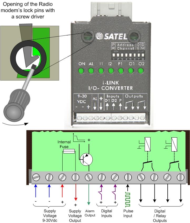
6 1 GENERAL 1.1 SATEL i-link Pulse Counter and I/O -converter The SATEL i-link is a Point-to-Point or Point-to-Multipoint transparent I/O-converter with a pulse counter input. The device works together with SATELLINE-1870, -1870E and radio modems. In Point-to Point transmission the digital status information can be sent through the radio modem to output in the other end. In Point-to-Multipoint mode it is also possible to read information from pulse transponders. Point-to-Multipoint transmission is possible adopting software suitable for the SATEL i-link. Screw connectors from left to right 1 = minus i-link ground 3 = 9-30 VDC / - + Supply Voltage 4 = + OUT + out for other devices 5 = AL OUT Alarm output 6, 7 = I1, I2 Digital inputs 8 = 10 khz Pulse Input 9-12 = O1, O2 Digital outputs from internal relay contacts Indicators ON Power ON/OFF ALARM Failure in transmission/device I1, I2 Digital inputs O1, O2 Digital outputs P1 Pulse counter input DIP-Switches 8 pcs 1 PRTCL, Protocol 0=P-to-P, 1=Point-to-Multipoint 2, 3, 4, 5 / P-to-P ADDRESS. Max 15. 2, 3, 4, 5 / P-to-MP CHANNEL. 10 channels. 6 Transmission cycle 0= once/ second (by European standard) 1= 3 times/second 7 DE Alarm Delay. 1=ON. 0= OFF 8 SM Safe Mode. 1=ON. 0= OFF 6
7 2 SPECIFICATIONS FEATURE min-max typical note Supply Voltage Vdc Supply Voltage to i-link regulated by the radio modem (5.3 Vdc) Power consumption VA 40 12Vdc Serial Interface RS-232 ± 15 Vdc ± 6 Vdc active RS-232 Response time < 250 ms < bps Operational temperature o C Transfer rate 9600 bps PULSE COUNTER Inputs, 1 pc max. 10 khz Minimum pulse width 5 µs DIGITAL SIGNALS Inputs, 2 pcs 0 35 Vdc 0 30 Vdc resistive 4-5 kω, Outputs, 2 pcs 0 30 V DC/AC/1 A relay contacts (normal= open) INDICATORS Indicators Power ON/OFF, Digital IN/OUT, Alarm, Pulse IN. OTHER OUTPUTS Alarm Output Vdc / 30 ma Alarm= + supply voltage drive current 30 ma. GENERAL Housing Metal plate, painted Connectors 16 pins for radio modem 12 pins for other connections Size L x W x H 123 x 85 x 30 mm Weight 80 g Mounting Wall plate IP IP-20 Modem compatibility SATELLINE-1870, -1870E,
8 3 FUNCTIONS Screw connector functions 3.1 Supply Voltage, 9 30 Vdc o The minus contacts are in parallel. One is for the i-link and another can be used for external devices and connections. Plus (+) is for supply voltage. 3.2 Alarm output, AL OUT o The AL OUT is activated, when three transmission fails has occurred one after another. When activated the AL OUT goes to +VDC. Driving current is max. 30 ma OUT o + OUT is internally connected to + VDC through an automatic fuse. The supply voltage for other devices. o Connections can be taken from the +OUT. 3.4 Digital Inputs, I1, I2, and Outputs O1, O2 o Inputs, o 2 pcs. Activated with + VDC. A transmission is made always when there is a change in the input (P-to-P). Minimum Voltage for 1 -state triggering is 7 Vdc. o Outputs, o 2 pcs. Open relay contacts. Max. rating 9 30 VDC / AC / 1 A load. 3.5 Pulse Input Can be used only in Point-to-Multipoint mode. o For fast pulses. Maximum frequency is 10 khz. 3.6 Indicators o ON o Power ON/ OFF. Illuminated when +VCD is connected. Blinking, if the device is not working. o O1 O2, PO PO1 o Showing the status of the input and output. Illuminated when the consequently pin is activated. o ALARM o Illuminated, if a fail in transmission has occurred. If the i-link has not received confirmation to the sent message, it will repeat the transmission. Three fails in turn switches the AL OUT and the alarm LED ON. o I1 I2, PI1 PI2 o Showing the status of the Input. Illuminated when the consequently pin is activated. 8
9 3.7 DIP-Swithces SATEL i-link DIP -switches, 8 pcs 1 MP, Protocol-switch 1= M, for Point-to-Multipoint (Master-Slave) -operation 0= P, for Point-to-Point -operation Point-to-Multipoint operation mode 2, 3, 4, 5, ADDRESS Used in Point-to-Multipoint -operation to set channel for the sub-station. Maximum number of addresses is Address selection table DIP DIP = reserved for the Main Station = address = address = address = address = address = address = address = address = address = address = address = address = address = address = address 15 Point-to-Point operation mode 2, 3, 4, 5 CHANNEL Used in Point-to-Point-operation to select / change the operational channel. When the power is turned ON, the i-link reads the channel information from the DIP - switches. Default mode setting is , 1=up / 0=down. The channel can be changed by turning first the power OFF and then by setting the DIP - switches (channel selector) to selected channel position for example Channel selection table DIP =disable (channel selection is not in use) =ch =ch =ch =ch =ch =ch =ch =ch =ch =ch10 9
10 NOTE1! Check, that both i-links are set to the same channel before turning the power ON. New channel is activated when the power is turned ON. NOTE2! The i-link unit will not operate with these settings: 1011, 1100, 1101, 1110 or The power ON indicator starts to blink in case any of these settings has been chosen. ADDRESS/ CHANNEL/DE-SM 7 DE Delayed alarm o Immediate / Delayed Alarm In case of a failure in the transmission, the alarm output response can be selected from immediate alarm to 10 seconds delayed alarm. 8 SM Safe Mode o Unchanged output state / Safe Mode state In case a failure in transmission, the outputs can be set to remain their status (unchanged) or change to Safe Mode which will switch all outputs to OFF-position. Safe Mode timing follows the setting of the switch 7 DE, so it can be immediate or delayed by 10 seconds. Selection table of the Dip switches 7 and 8 7DE 8SM 0 0 = Immediate Alarm / No Safe Mode 0 1 = Immediate Alarm / Immediate Safe Mode 1 0 = Alarm delayed by 10 seconds / No Safe Mode 1 1 = Alarm delayed by 10 seconds / Safe Mode delayed by 10 seconds 6 Selecting of the transmission standard According to the European standard for free channel operation, the ratio of the transmission cycle must not be more than 10/90. This is active when the DIP-switch number 6 is 0. In position 1 the cycle is faster. Selection table of the DIP-switch number 6 0= one transmission cycle per second 1= 3 transmission cycles per second. 10

11 4 OPERATION The Operation mode is selected using the PRTCL-switch. The operations are Point-to-Point or Point-to-Multipoint. In Point-to-Point operation mode the system consists of one pair of units. The inputs of the unit are transmitted as outputs of the other unit. In Multipoint mode the main-station controls the sub-stations. 4.1 Point- to-point Point-to-Point operation is between two units. The inputs of the unit are transmitted as outputs of the other unit Updating Digital messages Digital information (relay, switch etc.) will be sent to the other unit always, when there is a change at the input Start of the Point-to-Point operation o Connect radio modem to i-link directly to its connector and check that it is locked. o The MP-switch must be 0, in the P-to-P-position. o Before connecting the device to a power supply, connect first all inputs and outputs that are to be used. o When both units have these basic settings the supply voltage can be connected. o Check that the channel switches 2, 3, 4, 5 = 0000, unless they are purposely selected for a specific channel for example 2, 3, 4, 5= 0101= channel 5 (see chapter 3.7 /channel selection table). 4.2 Point-to-Multipoint In this mode the program at the main station controls the units of the sub stations. The main station can drive one or more sub stations (maximum 15 pcs / system) Start of the Multipoint operation o Connect one SATELLINE radio modem to the COM-Port of the PC. o Connect the i-link slave(s) to the radio modems. o The MP - switch must be 1, in the P-to-MP-position. o Before connecting the device to a power supply, connect first all inputs and outputs that are to be used. o Set individual address to all slaves. (As this is a master slave operation, the slaves have to be addressed). All slaves must have different address (see chapter 3.7 /address selection table. o Start using the system by the master by opening the controlling program for example SATELLINK PC Pro etc. o With the program it is possible to turn ON / OFF the outputs and monitor the inputs. Please contact local SATEL distributor or visit SATEL s web site in order to get information of the multipoint commands. 11
12 5 FACTORY SETTINGS SATEL i-link The i-link I/O -converter is shipped with the following default settings (unless specifically ordered with settings other than those listed below): FIXED SETTINGS DEFINED AT THE TIME OF ORDER PM, protocol switch, P-to-P or Multipoint 0 = Point-to-Point ADDRESS/CHANNEL 0000 = No address Transmission cycle 0 = 1/sec (European std.) DE, Alarm delay 0 = No Delay SM, Safe mode 0 = No Safe Mode 12

13 6 CONNECTION EXAMPLES Point-to-Multipoint Point-to-Point 13

14 7 ACCESSORIES SATELLINK PC and SATELLINK PC Pro Programs that make it possible to operate a Multipoint system with a PC. Layout of the SATELLINK PC Pro Multipoint-program 14
SATEL I-LINK 100 MB I/O-converter User Guide, Version 1.1
 TABLE OF CONTENTS TABLE OF CONTENTS... 1 IMPORTANT NOTICE... 2 PRODUCT CONFORMITY... 3 WARRANTY AND SAFETY INSTRUCTIONS... 4 1 GENERAL... 5 1.1 SATEL I-LINK 100 MODBUS I/O- CONVERTER... 5 2 SPECIFICATIONS...
USER GUIDE M2M Point to Multipoint
 USER GUIDE M2M Point to Multipoint TABLE OF CONTENTS 1 INSTALLATION... 3 1.1 SUB-STATIONS... 3 1.2 MASTER STATION (PC)...3 2 CONNECTING THE INPUTS AND OUTPUTS... 4 2.1 DIGITAL CONNECTIONS... 4 2.2 ANALOG
Version 2.1 SATEL NMS PC
 SATEL NMS PC USER MANUAL 1 Table of contents TABLE OF CONTENTS... 2 1 INTRODUCTION... 6 2 SAFETY INSTRUCTIONS... 7 3 3.1 3.1.1 3.1.2 3.1.3 3.2 3.2.1 3.2.2 3.2.3 3.2.4 NMS FUNDAMENTALS... 8 General NMS
DIGITAL DISPLAY. for Industry Applications. Series WAY-SSI. Key-Features:
 DIGITAL DISPLAY for Industry Applications Series WAY-SSI Key-Features: Content: Technical Data.2 Technical Drawing...2 Electrical Connection...3 Description...4 Order Code & Accessories...6 - WAY-SSI-S:
VISY-Output 8. Technical Documentation. 8-Channel relay output module. Version: 3 Edition: Art. no.:
 Technical Documentation VISY-Output 8 8-Channel relay output module Version: 3 Edition: 2016-09 Art. no.: 350072 FAFNIR GmbH Schnackenburgallee 149 c 22525 Hamburg Germany Tel.: +49 / 40 / 39 82 07 0 Fax:
MAXIMA + Series ROTARY LEVEL CONTROL
 Price $5.00 MAXIMA + Series ROTARY LEVEL CONTROL OPERATING INSTRUCTIONS PLEASE READ CAREFULLY Division of Garner Industries 7201 North 98th Street Lincoln, NE 68507-9741 (402) 434-9102 925-0268 Rev. A
MAXIMA+ Series Rotary Level Indicator
 MAXIMA+ Series Rotary Level Indicator BinMaster: Division of Garner Industries 7201 N. 98th St., Lincoln, NE 68507 402-434-9102 email: info@binmaster.com www.binmaster.com OPERATING INSTRUCTIONS PLEASE
PTC-101-M12 Hardware Installation Guide
 PTC-101-M12 Hardware Installation Guide Moxa Industrial Media Converter Third Edition, May 2014 2014 Moxa Inc. All rights reserved. P/N: 1802001016021 Overview The PTC-101-M12 industrial media converter
RADIO REMOTE CONTROLLER SET RE-4K
 RADIO REMOTE CONTROLLER SET RE-4K re4k_en 09/11 The RE-4K four-channel radio remote controller set enables electrical equipment to be remotely controlled by means of radio transmitters (remote keyfobs).
GSM SECURITY AND CONTROL SYSTEM ESIM021
 GSM SECURITY AND CONTROL SYSTEM ESIM021 Manual v1.1 Safety instructions Please read and follow these safety guidelines in order to maintain safety of operators and people around: Alarm and control system
SER-4485-SI-M USER S MANUAL
 SER-4485-SI-M USER S MANUAL 2017 May Edition Titan Electronics Inc. Web: www.titan.tw The computer programs provided with the hardware are supplied under a license. The software provided should be used
Operating instructions AC010S Compact AS-i E-STOP safety module
 Operating instructions AC010S Compact AS-i E-STOP safety module Sachnr. 7390636_/00 05/2007 Contents Safety instructions............................. 3 Installation / Setup............................
OZONE SWITCH Model OS-6. OS-6 Features
 USER MANUAL OZONE SWITCH Model OS-6 OS-6 Features The OS-6 is an industrial grade ozone controller and monitor. The OS-6 design is optimized for accuracy and ease of installation, setup and operation.
Heating Circuit Controller
 2 706 Synco living Heating Circuit Controller RRV918 RF-controlled heating circuit controller for up to 8 heating circuits RF communication based on KNX standard (868 MHz, bidirectional) Connection facility
Connecting a Cisco Output Module
 CHAPTER 5 Overview The optional Cisco Output Module (Figure 5-1) is attached to a Cisco Physical Access Gateway or Cisco Reader Module to provide additional connections for up to 8 outputs, each of which
GSM-X. Communication module. Quick installation guide. Full manual is available on Firmware version 1.02 gsm-x_sii_en 08/18
 GSM-X Communication module Quick installation guide Full manual is available on www.satel.eu Firmware version 1.02 gsm-x_sii_en 08/18 SATEL sp. z o.o. ul. Budowlanych 66 80-298 Gdańsk Poland tel. +48 58
Arctic Modbus Gateway Configuration Manual
 Copyright and Trademark Copyright 2004, Viola Systems Ltd. All rights to this manual are owned solely by Viola Systems Ltd. (referred in this manual as Viola Systems). All rights reserved. No part of the
RXTP ROOM TEMPERATURE
 ROOM TEMPERATURE CONTROLLER WITH PI CONTROL Mounting and operating instructions Table of contents SAFETY AND PRECAUTIONS 3 PRODUCT DESCRIPTION 4 ARTICLE CODES 4 INTENDED AREA OF USE 4 TECHNICAL DATA 4
Digital Keypad Introduction
 K2 Digital Keypad Introduction The K02 uses the latest microprocessor technology to operate door strikes and security systems that require a momentary (timed) or latching dry contact closure. All programming
Eco Sensors OZONE CONTROLLER Model OS-6 Instructions for Use. General and New Features
 Eco Sensors OZONE CONTROLLER Model OS-6 Instructions for Use General and New Features The OS-6 is an industrial grade Ozone controller and monitor. The OS-6 design has been optimized for accuracy, ease
DIN-RAIL EXPANDER int-iors_en 10/14
 INT-IORS INT-ORS DIN-RAIL EXPANDER int-iors_en 10/14 The INT-IORS expander enables the system to be expanded by 8 programmable wired zones and 8 programmable wired outputs. The INT-ORS expander enables
Digital input modules
 8 172 TX-I/O Digital input modules TXM1.8D TXM1.16D Two fully compatible versions: TXM1.8D: 8 inputs, each with a three-color LED (green, yellow or red) TXM1.16D: As TXM1.8X, but 16 inputs, each with a
CFO100 Series. User Manual CRT141 & CRR141. CFO141 User Manual, , rev001
 CFO00 Series User Manual CRT4 & CRR4 CFO4 User Manual, 5930005, rev00 Contents Introduction... Optical Transmitter CRT4 (version B)...2 General...2 Frame Installation...2 Video Input and Indicator Led...2
M-bus web server. Meters and Energy Cost Allocation WTV676-HB6035
 Meters and Energy Cost Allocation M-bus web server WTV676-HB6035 The web server reads out wireless or wired M-bus devices over Ethernet or the Internet using a browser. Power and connection for up to 20
DELOMATIC - MULTI-FUNCTION SYSTEM PART 2 INSTALLATION INSTRUCTION
 CONTENTS: 25.0...2 25.1 SYSTEM INSTALLATION...2 25.1.1 Before installing the DELOMATIC system...2 25.1.2 Installing the DGU...3 25.1.3 Installing the CP...4 25.1.4 Connecting the power supply...6 25.1.5
HITACHI. EH-150 series PLC EH-RTD8 Resistance Temperature Detective input module Instruction manual. Safety precautions
 HITACHI EH-150 series PLC Resistance Temperature Detective input module Instruction manual Thank you for purchasing a Hitachi Programmable Logic Controller. To operate it safely, please read this instruction
Heating Circuit Controller
 2 705 Synco 900 Heating Circuit Controller RRV912 RF-controlled heating circuit controller for up to 2 heating circuits RF communication based on KNX standard (868 MHz, bidirectional) Connection facility
V E1B Snap-in I/O Module
 V200-18-E1B Snap-in I/O Module The V200-18-E1B plugs directly into the back of compatible Unitronics OPLCs, creating a selfcontained PLC unit with a local I/O configuration. Features 16 isolated digital
MODEL KP-100 ACCESS CONTROL DIGITAL KEYPAD OPERATING INSTRUCTIONS
 MODEL KP-100 ACCESS CONTROL DIGITAL KEYPAD OPERATING INSTRUCTIONS Model KP-100 is a self-contained digital keypad. This keypad is suitable for residential, industrial, and commercial installations. It
MODEL: R1M-P4. PC Recorders R1M Series. SPECIFICATIONS OF OPTION: Q COATING (For the detail, refer to M-System's web site.)
") PC Recorders Series PC RECORDER (4 totalized counter inputs, 8 contact inputs and outputs) Functions & Features Industrial recorder on PC Totalized counter inputs Counts stored in E 2 PROM Easy system
PC Recorders Series PC RECORDER (4 totalized counter inputs, 8 contact inputs and outputs) Functions & Features Industrial recorder on PC Totalized counter inputs Counts stored in E 2 PROM Easy system
V E2B Snap-in I/O Module
 V200-18-E2B Snap-in I/O Module The V200-18-E2B plugs directly into the back of compatible Unitronics OPLCs, creating a selfcontained PLC unit with a local I/O configuration. Features 16 isolated digital
RXTH DUAL ROOM SENSOR / SWITCH
 DUAL ROOM SENSOR / SWITCH FOR TEMPERATURE AND RELATIVE HUMIDITY Mounting and operating instructions Table of contents SAFETY AND PRECAUTIONS 3 PRODUCT DESCRIPTION 4 ARTICLE CODES 4 INTENDED AREA OF USE
OPERATOR MANUAL OSD157 FIBER OPTIC RS422/RS232 MODEM/MULTIPLEXER
 / OPERATOR MANUAL OSD157 FIBER OPTIC RS422/RS232 MODEM/MULTIPLEXER PAGE 2 OF 17 INDEX 1 1. TECHNICAL SUMMARY... 4 1.1 BRIEF DESCRIPTION... 4 1.1.1 OVERVIEW... 4 1.1.2 APPLICATIONS... 4 1.1.3 FEATURES AND
Eco Sensors OZONE CONTROLLER Model OS-6 Instructions for Use. General and New Features
 Eco Sensors OZONE CONTROLLER Model OS-6 Instructions for Use General and New Features The OS-6 is an industrial grade Ozone controller and monitor. The OS-6 design has been optimized for accuracy, ease
Non-communicating room controllers
 3 882 DESIGO RXA Non-communicating room controllers RXA29.1 For fan-coil systems The RXA29.1 room controller are used for temperature control in individual rooms. For 2-pipe or 4-pipe fan-coil systems,
OPERATING INSTRUCTIONS 7 SERIES STATIC GENERATORS
 OPERATING INSTRUCTIONS 7 SERIES STATIC GENERATORS GB Contents Page 1 Introduction 4 2 Safety 5 3 Use 6 4 Checking on Delivered Equipment 6 5 General Specification and Dimensions 7 6 Positioning 10 7 Operating
MAXIMA + Series ROTARY LEVEL CONTROL
 Price $5.00 MAXIMA + Series ROTARY LEVEL CONTROL OPERATING INSTRUCTIONS PLEASE READ CAREFULLY Division of Garner Industries 7201 North 98th Street Lincoln, NE 68507-9741 (402) 434-9102 925-0268 TABLE OF
Blue LED Pulsed Light Source LS-475. Installation and Operation Manual Document Number
 Blue LED Pulsed Light Source LS-475 Installation and Operation Manual Document Number 000-10000-100-02-1209 Offices: Ocean Optics, Inc. 830 Douglas Ave., Dunedin, FL, USA 34698 Phone 727.733.2447 Fax 727.733.3962
User Manual. MS657140X Industrial Fast Ethernet Switch 8x 10/100Base-TX
 User Manual MS657140X Industrial Fast Ethernet Switch 8x 10/100Base-TX CE MARKING This equipment complies with the requirements relating to electromagnetic compatibility, EN 55022 class A for ITE, the
Installation and Hardware Guide
 Helios W.E.S. 1000 & 2000 (Wireless Emergency Stop) Installation and Hardware Guide E5, Version 1.3 Helios Global Tech Ltd. Contact Information Helios Global Technologies 1920 Windsor Rd Kelowna BC V1Y
EX-RC1 Remote I/O Adapter
 EX-RC1 Remote I/O Adapter The EX-RC1 interfaces between Unitronics Vision OPLCs and remote I/O Expansion Modules distributed throughout your system. The adapter is connected to a PLC via CANbus. Each adapter
Industrial Serial RS-232 to Fiber Converter. KSC-200 Series. Installation Guide
 Industrial Serial RS-232 to Fiber Converter KSC-200 Series Installation Guide DOC.100803-KSC-200-1- (C) 2006 KTI Networks Inc. All rights reserved. No part of this documentation may be reproduced in any
Operating instructions AS-i SmartLine module AC3200 AC /00 06/2016
 Operating instructions AS-i SmartLine module AC3200 AC3201 80237876/00 06/2016 Contents 1 Preliminary note...3 1.1 Symbols used...3 1.2 Warnings used...3 2 Safety instructions...3 2.1 General...3 2.2 Target
PI-EX-ME-2NAM/COC-24VDC
 Ex-i NAMUR Isolation Amplifier, With Intrinsically Safe Input and Relay Output, PDT, Two-Channel, 4 V DC Supply INTERFACE Data Sheet 0033_0_en PHOENIX CONTACT - /007 Description The PI-EX-ME-NAM/COC-4VDC
Multi-drop Profibus Fiber Optic Converter
 Multi-drop Profibus Fiber Optic Converter User Manual Table of Contents 1. Overview...3 1.1 Introduction...3 1.2 Technical Specification....3 1.3 Warranty..........4 2. Installation...4 2.1 Package Contents.....5
MC 11 EB-2 Power supply cabinet with external bus, AC version
 MC 11 EB-2 Power supply cabinet with external bus, AC version USER/MAINTENANCE MANUAL 1 SLOT 0 SLOT 1 SLOT 2 SLOT 3 SLOT 4 SLOT 5 SLOT 6 SLOT 7 SLOT 8 SLOT 9 SLOT 10 SLOT 11 EB-2 (a) MC11 (b) (c) Figures
IO-DI8-TO8, IO-DI8-TO8-L I/O Expansion Modules 8 Inputs, 8 Outputs
 IO-DI8-TO8, IO-DI8-TO8-L I/O Expansion Modules 8 Inputs, 8 Outputs The IO-DI8-TO8 and IO-DI8-TO8-L are I/O expansion modules that can be used in conjunction with specific Unitronics OPLC controllers. The
Docking station Order no Operation and installation instructions. 1 Safety instructions. 2 Structure of the device.
 Docking station Order no. 2883.. Operation and installation instructions 1 Safety instructions Electrical equipment must only be installed and assembled by qualified electricians. Always follow the relevant
ES-600 Ozone Controller Operation Manual
 ES-600 Ozone Controller Operation Manual Questions about your product? Find answers here: Web: www.ozonesolutions.com/es-600 Phone: 712-439-6880 Ozone Solutions OZONE CONTROLLER Model ES-600 Instructions
Serial Data DIN Fiber Link System
 USER GUIDE RLH Industries, Inc. The leader in rugged fiber optic technology. U-120 2017A-0420 DIN Fiber Link System COMPACT, RUGGED & TEMPERATURE HARDENED Introduction The DIN Fiber Link system transports
User Guide. Control Box. RoscoLED TM.
 RoscoLED TM Control Box User Guide This guide applies to the following RoscoLED Control Box models: RoscoLED Control Box 300W/Static White (293 22250 0000) RoscoLED Control Box 400W/VariWhite (293 22260
RTU560 Connections and Settings DIN Rail RTU 560CIG10
 Connections and Settings DIN Rail RTU 560CIG10 Application, characteristics and technical data have to be taken from the hardware data sheet: 560CIG10 1KGT 150 719 Operation The 560CIG10 is a DIN rail
Industriefunkuhren. Technical Manual. Signal Converter. for DIN Rail Mounting Series 4800xx-yy ENGLISH
 Industriefunkuhren Technical Manual Signal Converter for DIN Rail Mounting Series 4800xx-yy ENGLISH Version: 01.01-19.07.2007 2 / 23 Signal Converter 4800 - V01.01 INPORTANT NOTES Downloading Technical
RST ROOM TEMPERATURE TRANSMITTER. Mounting and operating instructions
 Mounting and operating instructions Table of contents SAFETY AND PRECAUTIONS 3 PRODUCT DESCRIPTION 4 ARTICLE CODES 4 INTENDED AREA OF USE 4 TECHNICAL DATA 4 STANDARDS 4 OPERATIONAL DIAGRAM 5 WIRING AND
RTT2 ROOM TEMPERATURE SWITCH. Mounting and operating instructions
 Mounting and operating instructions Table of contents SAFETY AND PRECAUTIONS PRODUCT DESCRIPTION ARTICLE CODES INTENDED AREA OF USE TECHNICAL DATA STANDARDS OPERATIONAL DIAGRAMS WIRING AND CONNECTIONS
Installation instructions RF-identification system with integrated AS-i slave DTSLF / / 2010
 Installation instructions RF-identification system with integrated AS-i slave UK DTSLF 704153 / 07 04 / 2010 Inhalt 1 Preliminary note...4 1.1 Symbols used...4 2 Safety instructions...4 2.1 General...4
OPERATOR MANUAL OSD730 FULL DUPLEX FOUR CHANNEL DIGITAL AUDIO/DATA SYSTEM
 OPERATOR MANUAL OSD730 FULL DUPLEX FOUR CHANNEL DIGITAL AUDIO/DATA SYSTEM INDEX 1 1. TECHNICAL SUMMARY... 4 1.1 BRIEF DESCRIPTION... 4 1.1.1 OVERVIEW... 4 1.1.2 APPLICATIONS... 4 1.1.3 FEATURES AND BENEFITS...
Kinetix 300 Memory Module Programmer
 Kinetix 300 Memory Module Programmer Catalog Number 2097-PGMR Topic About the Memory Module Programmer 1 Parts List 3 Batteries Operation 4 Using Memory Module Programmer 6 Switch On/Off Memory Module
IO-DI8-TO8 I/O Expansion Module 8 Inputs, 8 Outputs
 IO-DI8-TO8 I/O Expansion Module 8 Inputs, 8 Outputs The IO-DI8-TO8 is an I/O expansion module that can be used in conjunction with specific Unitronics OPLC controllers. The module offers 8 digital inputs,
Channel Switch CS. General Operating, Maintenance and Installation Manual
 Channel Switch CS General Operating, Maintenance and Installation Manual D-91056 Erlangen Phone: +49 9131 7677 47 Fax: +49 9131 7677 74 Internet: http://www.ipcomm.de Email: info@ipcomm.de Edition September
User Manual. MS657208X Industrial Gigabit Ethernet Switch 8x 10/100/1000Base-T
 User Manual MS657208X Industrial Gigabit Ethernet Switch 8x 10/100/1000Base-T CE MARKING This equipment complies with the requirements relating to electromagnetic compatibility, EN 55022 class A for ITE,
V E1B Snap-in I/O Module
 V200-18-E1B Snap-in I/O Module The V200-18-E1B plugs directly into the back of compatible Unitronics OPLCs, creating a selfcontained PLC unit with a local I/O configuration. Features 16 isolated digital
PKP Prozessmesstechnik GmbH. Borsigstrasse 24. D Wiesbaden-Nordenstadt. Tel: / Fax: / Operating manual PSA06
 PKP Prozessmesstechnik GmbH Borsigstrasse 24 D-65205 Wiesbaden-Nordenstadt Tel: 06122 / 7055-0 Fax: 06122 / 7055 50 Operating manual PSA06 Electronical pressure switch Content Page 19-34 1. Foreword 19
Room Temperature Controller
 3 023 Room Temperature Controller for four-pipe fan coil units RCC30 Outputs for on / off valve actuators Outputs for three-speed fan Control depending on room or return air temperature Operating modes:
POE084824B. PoE 54V/8x0,3A/4x7Ah PoE buffer power supply for up to 8 IP camera. v.1.1 EN* Edition: 7 from
 POE084824B v.1.1 PoE 54V/8x0,3A/4x7Ah PoE buffer power supply for up to 8 IP camera. EN* Edition: 7 from 15.11.2017 Supersedes the edition: 6 from 22.11.2016 GREEN POWER CCTV PoE PSU features: DC 54V uninterruptible
INDUSTRIAL 1000BASE-T TO 1000BASE-X MEDIA CONVERTERS. KCD-400 Series. Installation Guide
 INDUSTRIAL 1000BASE-T TO 1000BASE-X MEDIA CONVERTERS KCD-400 Series Installation Guide DOC.060227-KCD-400-1- (C) 2005 KTI Networks Inc. All rights reserved. No part of this documentation may be reproduced
Enhanced Mini-Chansim Model VCS-232
 Enhanced Mini-Chansim Model VCS-232 Operations Manual ViaSat Inc. 6155 El Camino Real Carlsbad, CA 92009 http://www.viasat.com SAFETY WARNING Always observe standard safety precautions during installation,
Advant OCS. The Compact and Cost Effective Advant Controller. Advant Controller 210. Open Control System
 Advant OCS Open Control System Advant Controller 210 The Compact and Cost Effective Advant Controller Advant Controller 210 is a small, cost-effective system belonging to the Advant Controller family.
Quick Start Installation Guide
 apc/l Quick Start Installation Guide Version A2 Document Part Number UM-201 May 2010 OVERVIEW The apc/l is an intelligent access control and alarm monitoring control panel which serves as a basic building
Contents Safety precautions Product components Optional accessories Names of each parts Product Dimension Cables and Connectors Power Connection
 Contents Safety precautions Product components Optional accessories Names of each parts Product Dimension Cables and Connectors Power Connection LAN Connection RS485 Connection Relay Connection Digital
KUUMIC OY DATA TRANSFER FALLBACK SWITCH KU113. Technical Reference
 FALLBACK SWITCH Technical Reference CONTENTS 1. GENERAL...1 1.1. INTRODUCTION...1 1.1.1. Basic functions...1 1.2. TECHNICAL SPECIFICATIONS...3 1.2.1. CONNECTORS...3 1.2.2. LED INDICATORS...5 1.2.3. JUMPERS
iologik E4200 Modular Active Ethernet I/O adaptor IT and Instrumentation for industry Introduction Specifications LAN Regulatory Approvals Warranty
 ioogik E4200 Modular Active Ethernet I/O adaptor Supports up to 16 I/O modules Dual Ethernet ANs and one RS-232 port Front-end intelligence that supports 80 Click&Go rules Unicode Active Messaging with
THANK YOU FOR VOTING TEXECOM INSTALLATION MANUAL. Digi-modems. Issue 3
 THANK YOU FOR VOTING TEXECOM INSTALLATION MANUAL Digi-modems Issue 3 Contents Com300 & Com2400 Installation Manual Contents 1. Regulatory Requirements... 3 General...3 Approval... 3 REN Rating... 3 2.
DESIGO RX Individual room controllers. for fan-coil systems, chilled ceilings and radiators, with LONMARK-compatible bus communications
 3 834 DESIO RX Individual room controllers for fan-coil systems, chilled ceilings and radiators, with MARK-compatible bus communications RXC20.1 RXC21.1 The RXC20.1 and RXC21.1 controllers are used for
MVS RAIL ELECTRONIC FAN SPEED CONTROLLER. Mounting and operating instructions
 DIN RAIL ELECTRONIC FAN SPEED Mounting and operating instructions Table of contents SAFETY AND PRECAUTIONS 3 PRODUCT DESCRIPTION 4 ARTICLE CODES 4 INTENDED AREA OF USE 4 TECHNICAL DATA 4 STANDARDS 5 WIRING
User Manual. PCKeypad Wireless Keypad
 User Manual PCKeypad Wireless Keypad Description The PCKeypad is a wireless keypad with a PentaCODE transmitter built-in. It works with all of Elsema s PCR series receivers. The installer has the option
CAN Repeater CAN-CR200, CAN-CR220, CAN-CR210/FO
 Hardware Manual CAN Repeater CAN-CR200, CAN-CR220, CAN-CR210/FO The expert for industrial and automotive communication IXXAT Headquarter US Sales Office IXXAT Automation GmbH IXXAT Inc. Leibnizstr. 15
Powerware 3105 UPS User s manual
 Powerware 3105 UPS 2005 Eaton Corporation All Rights Reserved The contents of this manual are the copyright of the publisher and may not be reproduced (even extracts) unless permission granted. Every care
TSD-SEQ6 Sequencer Controller
 Owner s Manual 1 AtlasSound.com Owner s Manual Description The Atlas Sound features 6 outputs that are configurable individually to be either a 24VDC output or Hard Switch Contact Closure (CC). There are
Powerware 3105 UPS User s manual
 Powerware 3105 UPS 2005 Eaton Corporation All Rights Reserved The contents of this manual are the copyright of the publisher and may not be reproduced (even extracts) unless permission granted. Every care
Extension module for lighting control
 s 3 842 DESIGO RXC Extension module for lighting control Extension to the RXC30 / RXC31 / RXC38 room controller RXC40.1 RXC40.5 The RXC40 extension module is used in conjunction with an RXC30, RXC31 or
2 Table of Contents 1. TABLE OF CONTENTS. 1. Table of Contents Introduction Wiring Diagram Terminals Review...
 TPR-6 Temperature Protection Relay Instruction Manual Ver. June 1 st 2010 2 Table of Contents 1. TABLE OF CONTENTS 1. Table of Contents... 2 2. Introduction... 3 3. Wiring Diagram... 5 4. Terminals Review...
SCHOTT FLM 4 Fiber Lighting Modul. Operating Instructions
 SCHOTT FLM 4 Fiber Lighting Modul Operating Instructions Contents 1. Important information 3 2. Scope of Delivery 3 3. Intended use 3 4. Safety information 4 5. Operation 5 5.1. LED Optics Module 5 5.2.
MXIO. Compact I/O module. Summary. Application Compact I/O module for data acquisition and HVAC control systems. Function
 MXIO Compact I/O module Summary The MXIO multiple I/O compact module is a microprocessor-controlled, communicative module with the I/O mix optimized for larger HVAC control applications. The module uses
PQ V ac. CONTROL PANEL 230V FOR ROLLING SHUTTERS Instructions Manual. Control panel for electric rolling shutters 230Vac TECHNICAL FEATURES
 CONTROL PANEL 230V FOR ROLLING SHUTTERS Instructions Manual Q45 230V ac Control panel for electric rolling shutters 230Vac Built-in radio receiver 433Mhz Adjustable pause time for automatic closing function
Sartorius Research. R 160 P Electronic Semi-Microbalance
 Sartorius Research. R 160 P Electronic Semi-Microbalance Installation and Operating Instructions 1 Power receptacle, fuse, 8 Level indicator voltage selector 9 ON/OFF key 2 Menu access switch 10 Print
VCL-TP, Teleprotection Equipment With Trip Counter Display Panel
 VCL-TP, Teleprotection Equipment With Trip Counter Display Panel Data Sheet Copyright: Valiant Communications Limited. 2008-2014 1 Product Overview VCL-TP, Teleprotection Equipment is an extremely reliable
Fiber optic converter audio and CAN TA OPERATION MANUAL
 Fiber optic converter audio and CAN TA-110.1 IOA110-1 March 2009 LANEX S.A., Technical support: tel. ul.ceramiczna 8, 20-150 Lublin tel. +48 81 443 96 36 Contents 1. General Characteristics.... 5 1.1.
ERF910. RF Repeater. Synco living
 2 704 Synco living RF Repeater ERF910 Wireless RF repeater for extending plant RF communication based on KNX standard (868 MHz, bidirectional) Mains-powered AC 2 V (with external power pack) Use For integration
PCLD-8751 PCLD User Manual
 PCLD-8751 48-Channel Opto-isolated D/I Board PCLD-8761 24-Channel Opto-isolated D/I and 24-Channel Relay Board User Manual Copyright The documentation and the software included with this product are copyrighted
MPI-DN, MPI-D MULTICHANNEL ELECTRONIC RECORDER for HART or RS-485/ MODBUS RTU SENSORS
 MPI-DN, MPI-D MULTICHANNEL ELECTRONIC RECORDER for HART or RS-485/ MODBUS RTU SENSORS 18 channels for HART / Modbus RTU sensors 2 digital channels 16 math channels 4 relay outputs for alarm or control
Electronic Multi-channel Load PMLA. 150 W / 600 W 40 V up to 240 V 1 A up to 120 A. Preliminary Edition
 Electronic Multi-channel Load PMLA 150 W / 600 W 40 V up to 240 V 1 A up to 120 A Preliminary Edition Functionality Interface Overview Master RS-232 X CAN O USB X Analog O LAN X Analog isoliert / GPIB
SoundwebTM. Installation Guide
 111 SoundwebTM Soundweb TM 9010 Installation Guide Soundweb TM Regulatory Information v1.0 PW/JMK 21st March 1999 An example of this equipment has been tested and found to comply with the following European
Operating Instructions for Differential Pressure Sensor. Model: PMP
 Operating Instructions for Differential Pressure Sensor Model: PMP 1. Contents 1. Contents... 2 2. Note... 3 3. Instrument Inspection... 3 4. Regulation Use... 3 5. Operating Principle... 4 6. Mechanical
AR10S-MF AR11S-MF AR40S-MF AR41S-MF Installation manual for mounting and connecting. Siemens AB. Version 5.0 A Security Products
 AR10S-MF AR11S-MF AR40S-MF AR41S-MF Installation manual for mounting and connecting Version.0 06.09.2013 Security Products Copyright Copyright Technical specifications and availability subject to change
TVAC25100 TVAC25110 User manual
 TVAC25100 TVAC25110 User manual Version 11/2010 Original user manual. Keep for future use. 12 Introduction Dear Customer, Thank you for purchasing this product. This product meets the requirements of the
STUDIO 1800 OPERATING INSTRUCTIONS MANUFACTURED IN THE UK
 STUDIO 1800 OPERATING INSTRUCTIONS MANUFACTURED IN THE UK The Studio 1800 is a combined Programmer and Temperature Controller which has been specifically designed for use with pottery kilns. Control of
Suprex Fiber Optic. Reader-Extender SPX-7400 SPX Product Manual. Reader-Extender. Manual. SPX-7400 Series EXP Suprex_FiberOptic_MAN_170502
 Suprex Fiber Optic Reader-Extender SPX-7400 SPX-7410 Product Manual Reader-Extender Manual SPX-7400 Series EXP-2000 Suprex_FiberOptic_MAN_170502 Cypress Integration Solutions 30+ Years of Access Control
24/48/120 VAC Interface Card Instruction Manual
 24/48/120 VAC Interface Card Instruction Manual Distributed by Ergonomic Partners Sales@ErgonomicPartners.com www.ergonomicpartners.com Tel: (314) 884-8884 April 2012 Part Number: -R2 Copyright 2012 Magnetek
For Powerful Digital Marketing and Total Multimedia Solution DV-6664 & DV-6664T. User s Guide version 1.0
 For Powerful Digital Marketing and Total Multimedia Solution DV-6664 & DV-6664T User s Guide version 1.0 Acknowledgements The MedeaWiz logo and DV-6664 are trademarks of MedeaWiz Corporation. All other