(IT) DIRETTIVA "RAEE" 2002/96/CE E SUCCESSIVA MODIFICA 2003/108/CE SUI RIFIUTI DI APPARECCHIATURE ELETTRICHE ED ELETTRONICHE
|
|
|
- Osborne Craig
- 5 years ago
- Views:
Transcription

1 eselect B2/B3
2

3 ESPANOL 3
4 (IT) DIRETTIVA "RAEE" 2002/96/CE E SUCCESSIVA MODIFICA 2003/108/CE SUI RIFIUTI DI APPARECCHIATURE ELETTRICHE ED ELETTRONICHE Il simbolo sotto riportato indica che il prodotto non può essere smaltito come normale rifiuto urbano. Le Apparecchiature Elettriche ed Elettroniche (AEE) possono contenere materiali nocivi per l'ambiente e la salute e pertanto devono essere oggetto di raccolta differenziata: smaltite quindi presso apposite discariche o riconsegnate al distributore a fronte dell'acquisto di una nuova, di tipo equivalente o facente le stesse funzioni. La normativa sopracitata, alla quale rimandiamo per ulteriori particolari e approfondimenti, prevede sanzioni per lo smaltimento abusivo di detti rifiuti. (UK) WASTE OF ELECTRICAL AND ELECTRONIC EQUIPMENT DIRECTIVE (WEEE, RAEE in Italy) 2002/96/EC AND SUBSEQUENT AMENDMENT 2003/108/EC The marking shown below indicates that the product cannot be disposed of as part of normal household waste. Electrical and Electronic Equipment (EEE) can contain materials harmful to health and the environment, and therefore is subject to separate waste collection: it must be disposed of at appropriate waste collection points or returned to the distributor against purchase of new equipment of similar type or having the same functions. The directive mentioned above, to which make reference for further details, provides for punitive actions in case of illegal disposal of such waste. (FR) DIRECTIVE "RAEE" 2002/96/CE ET MODIFICATION SUCCESSIVE 2003/108/CE CONCERNANT LES REBUTS D'APPAREILLAGES ÉLECTRIQUES ET ÉLECTRONIQUES Le symbole ci-dessous indique que le produit ne pas être éliminé comme un normal déchet urbain. Les Appareillages Électriques et Électroniques (AEE) peuvent contenir des matériaux nocifs pour l'environnement et la santé et doivent donc faire l'objet de collecte différenciée: éliminés donc auprès de décharges prévues à cet effet ou rendus au distributeur pour l'achat d'un nouveau, de type équivalent ou ayant les mêmes fonctions. La réglementation susmentionnée, à laquelle nous vous renvoyons pour les détails et les approfondissements ultérieurs, prévoit des sanctions pour la mise en décharge abusive desdits rebus. (ES) DIRECTIVA "RAEE" 2002/96/CE Y MODIFICACIÓ N SUCESIVA 2003/108/CE SOBRE RESIDUOS DE APARATOS ELÉ CTRICOS Y ELECTRÓ NICOS El símbolo que se muestra abajo indica que el producto no puede eliminarse como un residuo urbano normal. Los Aparatos Eléctricos y Electrónicos (AEE) pueden contener materiales nocivos para el medio ambiente y la salud y por tanto tienen que ser objeto de recogida selectiva: por consiguiente tienen que eliminarse en vertederos apropiados o entregarse al distribuidor cuando se adquiera uno nuevo, del mismo tipo o con las mismas funciones. La normativa mencionada arriba, a la que remitimos para más detalles y profundizaciones, prevé sanciones por la eliminación clandestina de dichos residuos.
5 Table of contents 1. GENERAL INFORMATIONS 2 2. TECHNICAL DATA 2 3. CONNECTIONS eselect B2 POWER SUPPLY CARD CONNECTIONS eselect B2 TTL OUTPUT CONNECTIONS eselect B3 POWER SUPPLY CARD CONNECTIONS eselect B3 TTL OUTPUT CONNECTIONS eselect B2/B3 PROBES CONNECTION 7 4. CONTROL PANEL DESCRIPTION eselect B2 CONTROL PANEL eselect B3 CONTROL PANEL LIGHT SIGNS KEYBOARD 9 5. DIMENSIONS PARAMETER DEFAULTS PROGRAMMING THE CONTROLLER STARTING CONTROLLER OPERATION THE DISPLAY IN THE VARIOUS OPERATION MODES (PH RX CL) PROGRAMMING PROCEDURE SIMPLE EXPERT PROGRAMMING MENU SETUP MENU METER TYPE T SENSOR SET TEMPERATURE CALIBRATION MENU TIMEOUT DELAY AT STARTUP AUX OUTPUT MODE YEAR, MONTH, DAY, HOUR, MINUTE SET PASSWORD SET DEFAULTS MENU SETPOINT1, SETPOINT SETPOINT MODE HYSTERESIS SETPOINT DELAY TTL MODE METER METER MENU CALIBRATION CALIBRATE ph 7/REF.POINT MENU ALARM MENU ALARM SETTINGS INPUT/OUTPUT CONNECTIONS PROXIMITY SENSORS PT100 CONNECTION PRIMING OF THE PUMPS 27 1
, Cl (ppm).")
6 1. GENERAL INFORMATIONS Electronic instruments controlling electrochemical parameters such as ph, Redox or Chlorine are widely used in swimming pools, waterworks and water treatment plants. The eselect Series Controllers stand out for the following features: Capability of performing the most possible measurements with just one type of electronic board: ph, Redox (mv), Cl (ppm). Simple and easy to learn programming procedure providing two types of menu: a SIMPLE menu allowing the user to control indispensable functions, and a EXPERT menu giving the user the full capability of setting all functions. Galvanically isolated electronics providing a high level of immunity to disturbances. 2. TECHNICAL DATA Input Voltage Parameter Power Consumption Value Vac 50/60Hz, Vdc, 24Vac 15 W (1 A peak current) Operating temperature range 0 40 C SETPOINT relay output terminals max current Auxiliary relay output terminals max current Alarm relay output terminals max current 16 ampere with resistive load 3 ampere with inductive load 5 ampere with resistive load 0.7 ampere with inductive load 5 ampere with resistive load 0.7 ampere with inductive load 2 setpoints 1 auxiliary output 1 alarm output Current output 4-20 ma (dynamic Ω) 2 current outputs TTL output pulse/min 2 open collector TTL outputs ph range ph resolution Rx range (mv) ± 1 mv Rx resolution Chlorine range 0 2; 0 20; 0 200; ppm 0,001/0,01/0,1/1 ppm Temperature range C 0.1 C Level control PT100 connection Relay output 6A (resistive load) 1A (inductive load) 2
7 3. CONNECTIONS 3.1. eselect B2 POWER SUPPLY CARD CONNECTIONS 3
8 3.2. eselect B2 TTL OUTPUT CONNECTIONS 4
9 3.3. eselect B3 POWER SUPPLY CARD CONNECTIONS 5
10 3.4. eselect B3 TTL OUTPUT CONNECTIONS 6
11 3.5. eselect B2/B3 PROBES CONNECTION A BNC connector for connecting ph or Redox probes, plus a 4-pin connector for connecting a Chlorine probe, are provided in the bottom of the instrument. The connection diagram is as follows: Power supply 4 pins connector: Pin 1 : White (+5V) Pin 2 : Not connected Pin 3 : Not connected Pin 4 : Brown (-5V) 7


12 4. CONTROL PANEL DESCRIPTION 4.1. eselect B2 CONTROL PANEL 4.2. eselect B3 CONTROL PANEL 8


13 4.3. LIGHT SIGNS SET 1 active SET 2 active 4.4. KEYBOARD Meter : Used to select the type of measurement METER 1, 2 or 3 ESC : Comes one step back in the programming procedure. Minus symbol : Decreases numbers and defines functions within specific programming menus. E.g.: when selecting the type of measurement allows the user to shift between ph, Rx and Chlorine. Plus symbol : Increases numbers and defines functions within specific programming menus. E.g.: when selecting the type of measurement allows the user to shift between ph, Rx and Chlorine. Shift right : Used to select the digit to modify when setting passwords. Used to change Language also. OK : Allows the user to proceed by confirming the selections made. 9
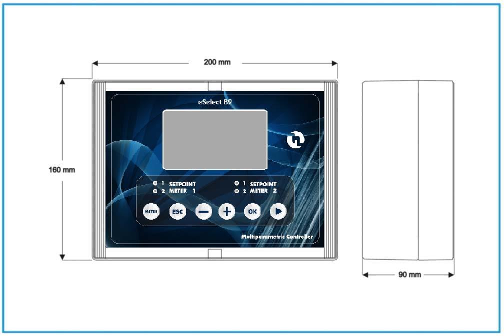
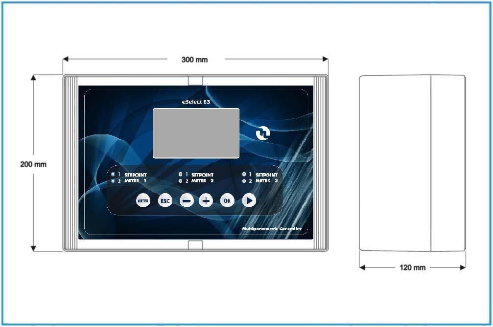
14 5. DIMENSIONS 10
15 6. PARAMETER DEFAULTS No. Function ph default Rx default mv Cl default 1 Setpoint Setpoint Type of action Acid Oxidising Direct 4 Hysteresis SETPOINT 1 and 2 actuation delay 00:03 m:s 00:03 m:s 00:03 m:s 6 TTL 1 and 2 outputs max frequency Measurement at TTL 1 and 2 max frequency ma output 1 and 2, measurement at 4 ma ma output 1 and 2, measurement at 20 ma Alarm high threshold Alarm low threshold Alarm overdosage (OVER) 99:59 h:m 99:59 h:m 99:59 h:m 13 Menu mode SIMPLE SIMPLE SIMPLE 14 Password OFF OFF OFF 15 Temperature unit C C C 16 Temperature compensation mode Manual 25 C Manual 25 C Manual 25 C 17 Calibration menu delay Actuation delay when switching on
16 7. PROGRAMMING THE CONTROLLER All programming parameters and modes of operation of the instrument can be set using its keyboard and dedicated display STARTING CONTROLLER OPERATION The instrument, according to its initial configuration, can be set to control three distinct types of measurements: ph, Rx or Chlorine. To perform that, when switching on the controller for the first time, the operator have to select the intended type of measurement by operating as follows: Upon switching on the instrument, press OK key to enter in the MENU SETUP. Than press OK to enter in and change SIMPLE with EXPERT by press + or key. Than change the METER TYPE in the complete MENU SETUP. MAIN SCREEN 2013/05/15 04:52 WEDNESDAY T=25 SET1:ON SET1:OFF 7.47 ph ma1:12,4 ma2:12,4 SET1:OFF SET1:ON 620mV ma1:10,4 ma2:10,4 Press OK key to enter into MENU MENU SETUP MENU SETPOINT1 MENU SETPOINT2 MENU CALIBRAZTION MENU ALARM Press METER key to choose METER 1, METER 2 or METER 3. When METER key is pressed the two red lamp associated to the setpoint of the METER choosed will light-on. MENU SETUP SIMPLE HOUR 4 MINUTE 52 12
17 MENU SETUP SIMPLE HOUR 5 MINUTE 55 Press + or to change SIMPLE to EXPERT MENU SETUP 1/2 EXPERT METER TYPE ph T SENSOR NONE SET TEMPERATURE 25.0 CALIBRATION MENU TIMEOUT 05:00 DELAY AT STARTUP 00:05 AUX OUTPUT MODE OFF HOUR 14 Press + or to change PARAMETER on left arrow MENU SETUP 1/2 EXPERT METER TYPE ph T SENSOR NONE SET TEMPERATURE 25.0 CALIBRATION MENU TIMEOUT 05:00 DELAY AT STARTUP 00:05 AUX OUTPUT MODE OFF Press + or to change PARAMETER on left arrow MENU SETUP 1/2 EXPERT METER TYPE ph T SENSOR NONE SET TEMPERATURE 25.0 CALIBRATION MENU TIMEOUT 05:00 DELAY AT STARTUP 00:05 AUX OUTPUT MODE OFF Press + or to choose ph, Rx,Cl After choose the METER TYPE press ESC key until see the main screen. Please note the ESC key permits to return to previous screen. 13
18 7.2. THE DISPLAY IN THE VARIOUS OPERATION MODES (PH RX CL) When the instrument is switched on, the display shows the measurement value and the type of measurement. 2013/05/15 04:52 WEDNESDAY T=25 SET1:ON SET1:OFF 7.47 ph ma1:12.4 ma2:12.4 SET1:OFF SET1:OFF 620mV ma1:4.0 ma2:4.0 eselect B2 main screen METER 2: STANDBY 2013/05/15 04:52 WEDNESDAY T=25 SET1:ON SET1:OFF 7.47 ph ma1:12.4 ma2:12.4 SET1:OFF SET1:ON 620mV ma1:10.4 ma2:10.4 eselect B3 main screen SET1:OFF SET1:ON Cl ppm ma1:10.4 ma2:10.4 METER 3: ALARM: MAX 7.3. PROGRAMMING PROCEDURE When installing the controller for the first time, the user must configure it depending on the intended type of measurement or control. The first action for the user to carry out is setting the operation modes for every measurement outlet: METER 1 and METER 2 for B2 controller, and METER 1, METER 2 and METER 3 for B3 controller. When setting the instrument, it is advisable to follow the programming procedure outlined below. Conversely, if only a single parameter must be changed, it is advisable to go directly to the menu comprising the concerned function, and perform the necessary changes or settings. Please note there are two different : SIMPLE and EXPERT and they allow to change different parameters. EXPERT MENU allow to change all parameters but it is recommended to modify its parameters from qualified personnel SIMPLE MENU SETUP SIMPLE HOUR 4 MINUTE 52 It permits to set the following parameters: 14
19 : SIMPLE or EXPERT YEAR: put the current YEAR MONTH: put the current MONTH DAY: put the current DAY HOUR: put the current HOUR MINUTE: put the current MINUTE EXPERT MENU SETUP 1/2 EXPERT METER TYPE ph T SENSOR NONE SET TEMPERATURE 25 CALIBRATION MENU TIMEOUT 05:00 DELAY AT STARTUP 00:05 AUX OUTPUT MODE OFF HOUR 14 MENU SETUP 2/2 MINUTE 52 SET PASSWORD SET DEFAULTS NO It permits to set the following parameters by use : : SIMPLE or EXPERT METER TYPE: ph, Rx, Cl 20ppm,Cl 2ppm, Cl 200ppm, Cl 2000ppm TSENSOR: NONE or PT100 SET TEMPERATURE: put the current TEMPERATURE is PT100 is not setted CALIBRATION MENU TIMEOUT: set the TIMEOUT time for CALIBRATION procedure DELAY STARTUP: set the startup DELAY TIME for the instrument AUX OUTPUT MODE: set OFF or CLEANING or FLOCCULANT YEAR: put the current YEAR MONTH: put the current MONTH DAY: put the current DAY HOUR: put the current HOUR MINUTE: put the current MINUTE SET PASSWORD: put the password if it is necessary to have it SET DEFAULTS: set NO or MAINTAIN CALIBRATION or RESTORE ALL 15
20 7.4. PROGRAMMING MENU SETUP MENU SETUP 1/2 EXPERT METER TYPE ph T SENSOR NONE SET TEMPERATURE 25 CALIBRATION MENU TIMEOUT 05:00 DELAY AT STARTUP 00:05 AUX OUTPUT MODE OFF Chose the parameter by press + or key. Press OK key to confirm the choice and set the value for the parameter on right column. Modify the value for the parameter by press + or key. Press OK key to confirm the choice and return on left column to set an other parameters. Starting from the MAIN SCREEN press OK key until enter in. Than change SIMPLE to EXPERT by pressing + key or key. Change SIMPLE in EXPERT by press + or - key MENU SETUP SIMPLE HOUR 5 MINUTE 55 MENU SETUP 1/2 EXPERT METER TYPE ph T SENSOR NONE SET TEMPERATURE 25 CALIBRATION MENU TIMEOUT 05:00 DELAY AT STARTUP 00:05 AUX OUTPUT MODE OFF 16
21 MENU METER TYPE Starting from the MENU SETUP screen, enter in METER TYPE by pressing + key or key. After selected METER TYPE press OK key to set the meter type between ph, Rx, Cl 20ppm,Cl 2ppm, Cl 200ppm, Cl 2000ppm. MENU SETUP 1/2 EXPERT METER TYPE ph T SENSOR NONE SET TEMPERATURE 25 CALIBRATION MENU TIMEOUT 05:00 DELAY AT STARTUP 00:05 AUX OUTPUT MODE OFF MENU SETUP 1/2 EXPERT METER TYPE ph T SENSOR NONE SET TEMPERATURE 25 CALIBRATION MENU TIMEOUT 05:00 DELAY AT STARTUP 00:05 AUX OUTPUT MODE OFF Press + or to choose ph, Rx,Cl T SENSOR Starting from the MENU SETUP screen, enter in T SENSOR by pressing + key or key. After selected T SENSOR press OK key to set or not PT100 sensor. MENU SETUP 1/2 EXPERT METER TYPE ph T SENSOR NONE SET TEMPERATURE 25 CALIBRATION MENU TIMEOUT 05:00 DELAY AT STARTUP 00:05 AUX OUTPUT MODE OFF MENU SETUP 1/2 EXPERT METER TYPE ph T SENSOR NONE SET TEMPERATURE 25 CALIBRATION MENU TIMEOUT 05:00 DELAY AT STARTUP 00:05 AUX OUTPUT MODE OFF Press + or to choose NONE or PT100 sensor. 17
22 If PT100 will be set a PT100 sensor have to be connected to the dedicated connector. Selecting PT function, the temperature measured by PT100 probe is shown on the display (while the visualization of the measure is in progress). If NONE will be set it is possible to set the real temperature as show in next paragraph SET TEMPERATURE Starting from the MENU SETUP screen, if the PT100 sensor is not setted, enter in SET TEMPERATURE menu by pressing + key or key. After selected SET TEMPERATURE press OK key to set the temperature value. MENU SETUP 1/2 EXPERT METER TYPE ph T SENSOR NONE SET TEMPERATURE 25.0 CALIBRATION MENU TIMEOUT 05:00 DELAY AT STARTUP 00:05 AUX OUTPUT MODE OFF Press + or to choose the temperature value CALIBRATION MENU TIMEOUT It represent the exit delay time from the programming menu in case no keys are pressed during the probe calibration stage. Starting from the MENU SETUP screen, enter in CALIBRATION MENU TIMEOUT by pressing + key or key. After selected CALIBRATION MENU TIMEOUT press OK key to set the time value. MENU SETUP 1/2 EXPERT METER TYPE ph T SENSOR NONE SET TEMPERATURE 25.0 CALIBRATION MENU TIMEOUT 05:00 DELAY AT STARTUP 00:05 AUX OUTPUT MODE OFF Press + or to choose the time value (minutes and seconds) DELAY AT STARTUP It define the delay time of measurement actuation from switching on the instrument. Starting from the MENU SETUP screen, enter in DELAY AT STARTUP by pressing + key or key. After selected DELAY AT STARTUP press OK key to set the time value. MENU SETUP 1/2 EXPERT METER TYPE ph T SENSOR NONE SET TEMPERATURE 25.0 CALIBRATION MENU TIMEOUT 05:00 DELAY AT STARTUP 05:00 AUX OUTPUT MODE OFF Press + or to choose the time value (minutes and seconds). 18
23 AUX OUTPUT MODE The controller has a calendar and an internal clock for the management of the exits with timer and the storage of the data recorded by the controller; in order to set up the clock the following settings must be carried out. Once the date and time are set, by pressing the + or - key, the choice are the follow: OFF function: the aux output is deactivated; Cleaning function: it is possible to activate a dosing pump for the cleaning of the electrode, up to a maximum of 4 interventions (timer and scheduled mode) during the day; the difference from the flocculant mode, is that the Cleaning mode interrupts the tool s operations (disabling the set-point). At the end of such intervention the tool awaits the start up time (see DELAY AT STARTUP). Flocculant function: it is possible to activate the flocculant dosing system, up to a maximum of 4 interventions (timer and scheduled mode) during the day. Starting from the MENU SETUP screen, enter in AUX OUTPUT MODE by pressing + key or key. After selected AUX OUTPUT MODE press OK key to set between OFF, CLEANING and FLOCCULANT. MENU SETUP 1/2 EXPERT METER TYPE ph T SENSOR NONE SET TEMPERATURE 25.0 CALIBRATION MENU TIMEOUT 05:00 DELAY AT STARTUP 00:05 AUX OUTPUT MODE OFF Press + or to choose between OFF, CLEANING and FLOCCULANT. Once one of the two functions is activated (flocculant or cleaning) it is necessary to set the auxiliary outputs that need to be activated by select the days in which the auxiliary output needs to be activated CLEANING AUX OUTPUT MODE Starting from the MENU SETUP screen, and selected CLEANING as AUX OUTPUT MODE press OK key. Than Set CYCLE TIME, WEEKDAYS1, WEEKDAYS2, WEEKDAYS3, WEEKDAYS4 as follow: CYCLE TIME: define how long time the AUX OUTPUT relay have to be activated; WEEKDAYS1, WEEKDAYS2, WEEKDAYS3, WEEKDAYS4 : define the days of the week in wich the aux output have to be activated; after setting the WEEKDAYS on the display appear to set the START TIME FLOCCULANT AUX OUTPUT MODE Starting from the MENU SETUP screen, and selected FLOCCULANT as AUX OUTPUT MODE press OK key. Than Set CYCLE TIME, WEEKDAYS1, WEEKDAYS2, WEEKDAYS3, WEEKDAYS4 as follow: CYCLE TIME: define how long time the AUX OUTPUT relay have to be activated; WEEKDAYS1, WEEKDAYS2, WEEKDAYS3, WEEKDAYS4 : define the days of the week in wich the aux output have to be activated; after setting the WEEKDAYS on the display appear to set the START TIME 19
24 MENU SETUP 1/2 EXPERT METER TYPE ph T SENSOR NONE SET TEMPERATURE 25.0 CALIBRATION MENU TIMEOUT 05:00 DELAY AT STARTUP 00:05 AUX OUTPUT MODE CLEANING CYCLE TIME 01:00 WEEKDAYS 1 MO TU WE SA SU START TIME 1 02:00 Chose the parameter by press + or keys. Press OK key to confirm the choice and set the value for the parameter on right columm. Modify the value for the parameter by press + or and keys. Press OK key to confirm the choice and return on left columm to set an other parameter YEAR, MONTH, DAY, HOUR, MINUTE Starting from the MENU SETUP screen, enter in YEAR or MONTH or DAY or HOUR or MINUTE by pressing + key or key. For each of these parameters press press OK key and set the value on right columm SET PASSWORD As soon as the measurement is selected, proceeding within the SETUP menu, the user can decide to activate the password security and the relating 6 digits code. The password can be any number between and To set the value, for any digit use + or key and move to the next digit by press key. After setting all 6 digit press OK key to set the next parameter SET DEFAULTS Starting from the MENU SETUP screen, enter in SET DEFAULT by pressing + key or key. Than press OK key and set one of the followings: NO: to don t reset the parameters; MAINTAIN CALIBRATION: to reset all parameters and save only the calibration; RESTORE ALL: to reset all parameters. 20
25 7.5. MENU SETPOINT1, SETPOINT2 Starting from the MAIN SCREEN in EXPERT press OK key than press + key to move the selector on MENU SETPOINT1 or MENU SETPOINT2. Press OK key to enter. Please note starting from SIMPLE into the SETPOINT1 and SETPOINT2 it is possible to set only the SETPOINT value and the working MODE ( acid or alkaline ). MAIN SCREEN 2013/05/15 04:52 WEDNESDAY T=25 SET1:ON SET1:OFF 7.47 ph ma1:12.4 ma2:12.4 SET1:OFF SET1:ON 620mV ma1:10.4 ma2:10.4 Press OK key to enter into MENU SET1:OFF SET1:ON Cl ppm ma1:10.4 ma2:10.4 METER 3: ALARM: MAX MENU SETUP MENU SETPOINT1 MENU SETPOINT2 MENU CALIBRAZTION MENU ALARM MENU SETUP MENU SETPOINT1 MENU SETPOINT2 MENU CALIBRATION MENU ALARM MENU SETPOINT1 1/2 SETPOINT 7.20 MODE ACID HYSTERESIS 0.10 SETPOINT DELAY 00:03 TTL MODE PROPORTIONAL PULSE WIDTH 80 MAX F MAX FREQUENCY 120 MIN FREQUENCY 0 METER 0.00 Chose the parameter by press + or keys. Press OK key to confirm the choice and set the value for the parameter on right column. Modify the value for the parameter by press + or and keys. Press OK key to confirm the choice and return on left column to set an other parameter. 21
26 MENU SETPOINT1 2/2 METER SETPOINT After setting up the instrument, the SETPOINT values must be set: the instrument features two independent SETPOINTS ( SETPOINT1 and SETPOINT2 ) actuating two relating relay outputs. On the previous screen is show how set the values for these setpoints. After set the SETPOINT parameter, press OK key to move the cursor on right column and set the value by press + or keys. After set the setpoint value press OK key to confirm MODE Defining the type of actuation: ACID or ALKALINE in the case of ph, DOWN and UP in the case of REDOX and CL; they represents the action tends to decrease or increase the measurement. After set the MODE parameter, press OK key to move the cursor on right column and set the value by press + or keys. Press OK key to confirm the setted value HYSTERESIS After defining the type of actuation, setting the hysteresis value is the next step. After set the HYSTERESIS parameter, press OK key to move the cursor on right column and set the value by press + or keys. Press OK key to confirm the setted HYSTERESIS value SETPOINT DELAY The instrument allows the user to define a delay time relating to SETPOINT actuation. After set the SETPOINT DELAY parameter, press OK key to move the cursor on right column and set the value by press + or keys. Use the key to move from minutes to seconds. Press OK key to confirm the setted SETPOINT DELAY time. 22
27 TTL MODE The instrument features two TTL (1-2) outputs that can operate in the proportional or ON/OFF mode. After set the TTL MODE parameter, press OK key to choose the operation mode of the TTL output selected: PROPORTIONAL or ON/OFF. In the proportional mode the frequency of pulses decreases approaching the SETPOINT until the minimum set value is reached, whilst in the ON/OFF mode the TTL output is actuated when the corresponding SETPOINT relay changes its position. Press the OK key to confirm the choice. When choosing the proportional mode, four parameters must be set to allow the TTL output to operate correctly, as follows: PULSE WIDTH MAX F MAX FREQUENCY MIN FREQUENCY PULSE WIDTH This parameter represent the time during the which the TTL output is ON. After set the PULSE WIDTH parameter, press OK key to set the value VAL@MAX F This parameter represent the measure where the frequency of the TTL output is on MAX value. After set the VAL@MAX F parameter, press OK key to set the value MAX FREQUENCY This parameter represent the maximum frequency of the TTL output. After set the MAX FREQUENCY parameter, press OK key to set the value MIN FREQUENCY This parameter represent the minimum frequency of the TTL output. After set the MIN FREQUENCY parameter, press OK key to set the value METER This parameter represent the measure value where the output ma signal is equal to 4mA. After set the METER parameter, press OK key to set the value on right column METER This parameter represent the measure value where the output ma signal is equal to 20mA. After set the METER parameter, press OK key to set the value on right column. 23
28 7.6. MENU CALIBRATION Starting from the MAIN SCREEN press OK key than press + key to move the selector on MENU CALIBRATION. Press OK key to enter. MAIN SCREEN 2013/05/15 04:52 WEDNESDAY T=25 SET1:ON SET1:OFF 7.47 ph ma1:12.4 ma2:12.4 SET1:OFF SET1:ON 620mV ma1:10.4 ma2:10.4 Press OK key to enter into MENU SET1:OFF SET1:ON Cl ppm ma1:10.4 ma2:10.4 METER 3: ALARM: MAX MENU SETUP MENU SETPOINT1 MENU SETPOINT2 MENU CALIBRAZTION MENU ALARM MENU SETUP MENU SETPOINT1 MENU SETPOINT2 MENU CALIBRATION MENU ALARM MENU CALIBRATION CALIBRATE ph 7/REF. POINT 8.40 CALIBRATE BUFFER 4/ Calibration Menu for ph mode Chose the parameter by press + or keys. Press OK key to confirm the choice and set the value for the parameter on right column. Modify the value for the parameter by press + or and keys. Press OK key to confirm the choice and return on left column to set an other parameter. 24
29 CALIBRATE ph 7/REF.POINT The menu CALIBRATION allows the user to calibrate the instrument through the use of buffer solutions. After press CALIBRATE ph 7/REF. POINT dipping the probe in the ph 7 buffer solution is the calibration procedure s first step. When the reading is stable, adjust the value by using the + and keys and press key to confirm. The next step is to put the probe into ph 4 or ph 9 buffer solution and press OK on CALIBRATE BUFFER 4/9. When the reading is stable, adjust the value by using the + and keys and press key to confirm. The instrument is so calibrated. For Redox and Chlorine, calibrate first calibration point by using buffer solution (e.g. 650mV) o by using a photometer ( CALIBRATE BUFFER for REDOX and CALIBRATE DPD1 for CLORINE ). Second calibration point (available in EXPERT mode only) is the "ZERO", which is possible to calibrate by disconnect the probe and shortcutting BNC input connector MENU ALARM Starting from the MAIN SCREEN press OK key than press + key to move the selector on MENU ALARM. Press OK key to enter. MAIN SCREEN 2013/05/15 04:52 WEDNESDAY T=25 SET1:ON SET1:OFF 7.47 ph ma1:12.4 ma2:12.4 SET1:OFF SET1:ON 620mV ma1:10.4 ma2:10.4 Press OK key to enter into MENU SET1:OFF SET1:ON Cl ppm ma1:10.4 ma2:10.4 METER 3: ALARM: MAX MENU SETUP MENU SETPOINT1 MENU SETPOINT2 MENU CALIBRAZTION MENU ALARM MENU SETUP MENU SETPOINT1 MENU SETPOINT2 MENU CALIBRATION MENU ALARM 25
30 MENU ALARM MAX VALUE MIN VALUE 0.00 OVERDOSING TIME 99:59 Alarm Menu for ph mode Chose the parameter by press + or keys. Press OK key to confirm the choice and set the value for the parameter on right column. Modify the value for the parameter by press + or and keys. Press OK key to confirm the choice and return on left column to set an other parameter MENU ALARM SETTINGS The instrument features various alarms that can be configured by the user; three types of alarm can be set: MAX VALUE The instrument raises an alarm above a given measurement value. MIN VALUE The instrument raises an alarm below a given measurement value. OVERDOSING TIME The instrument raises an alarm when a given time interval has elapsed and the measurement has not come back to the intended setpoint values. 8. INPUT/OUTPUT CONNECTIONS 8.1. PROXIMITY SENSORS B2 and B3 controllers have one REMOTE input for each measure channel to which proximity sensor can be connected ( see page #4 for ESELECT B2 and page #6 for ESELECT B3 ). The proximity sensor when is inserted in the probe holder, signal the presence of water in the installation and therefore the need to start the inspection. In order to activate the controller, the proximity sensor should be Normally Closed. When there is no water flow ( the contact on REMOTE INPUT is open ) than a STAND-BY alarm will shows on the display. It is possible to use one proximity sensor for all input measure by put a short-circuit connector on slave position as show on the following scheme. If the short circuit connector is put on INDEPENDENT position the two REMOTE INPUTS will work separately. 26
31 8.2. PT100 CONNECTION As it is possible to see on the connection diagram represented in Fig. 1 the controller foresees the mounting of the PT100, 3 wire sensors. Regarding the two poles PT100 it is necessary to short circuit the two terminals of the clamps marked C with a clevis (fig.1) and connect the two wires of the PT100 between one of the above poles C and the third pole which is still free; instead for the four wire one it is necessary to connect both wires to one of the two pairs of twisted wires at the third pole and the other two wires of the other twisted pair to the two poles marked C. This jumper has to be positioned as indicated to select PT100 temperature sensor 8.3. PRIMING OF THE PUMPS To facilitate the priming of the pumps, it is possible to manually activate the output of the SETPOINT. Such procedure is accessible even in presence of password by pressing simultaneously two keys (as following described) while the visualization of the measure is in progress. The procedure of priming of the pumps involves: - Activation of the relay SETPOINT mA output is set to 20mA - If in ON/OFF mode, TTL relay is activated; if in PROPORTIONAL mode, the TTL output is set to the maximum frequency. To effect such operation: For the pump 1 press simultaneously the keys and. Until the keys stay pressed the whole outputs remain activated. For the pump 2 press simultaneously the keys + and. Until the keys stay pressed the whole outputs remain activated. 27
32
33
34

35 COD. DMU00193ML1-A ( )
Control instruments GUARDIAN 2 - GUARDIAN 3
 Control instruments GUARDIAN 2 - GUARDIAN 3 Table of contents 1. General informations... 3 2. Technical data... 3 3. GUARDIAN 2 connection diagram...4 3.1. TTL connection diagram for GUARDIAN 2 instrument...5
AG SELECT B1. OPERATING INSTRUCTIONS AND MAINTENANCE UNI EN ISO
 AG SELECT B1 www.etatronds.com UK OPERATING INSTRUCTIONS AND MAINTENANCE UNI EN ISO 9001-2008 Table of contents 1. General information...3 2. Technical data...3 3. Connection diagram...4 3.1. Chlorine
Control and automatic dosing
 Control and automatic dosing For public and residential pools Control Basic and Control Basic Plus Control Basic Next Optima and Optima Next dosing pumps Panels for the galvanic and amperometric control
LDCL DIGITAL CONTROLLER OPERATING MANUAL
 This manual contains important safety informations about installation and use of this equipment. Ignoring this informations could result in injuries or damages. It is strictly forbidden to use this equipment
JUMO ecotrans ph 03 Microprocessor transmitter/ switching device for ph/redox voltage and temperature
 Page 1/7 JUMO ecotrans 03 Microprocessor transmitter/ switching device for /Redox voltage and temperature with a 2-line LCD for mounting on a 35 mm DIN rail Brief description Depending on the configuration,
GENERAL SAFETY GUIDELINES
 This manual contains important safety information about installation and use of this equipment. Ignoring this information could result in injuries or damages. It is strictly forbidden to use this equipment
LCD LCDS LCDRI CONTROLLER OPERATING MANUAL
 This manual contains important safety information about installation and use of this equipment. Ignoring this information could result in injuries or damages. It is strictly forbidden to use this equipment
BL121 Pool & Spa Controller. ph/orp Swimming Pool Controller with Built-In Chemical Feed Pumps
 BL121 Pool & Spa Controller ph/orp Swimming Pool Controller with Built-In Chemical Feed Pumps Introduction The BL121 is an all-in-one solution for automatic control of ph and chlorine levels in swimming
CONTROLLERS. Chemical Injection skids. Water Quality Monitoring Systems cum dosing (WQMSD) Mobile Disinfection/Dosing systems
 Mobile Disinfection/Dosing systems") Chemical Injection skids CONTROLLERS Water Quality Monitoring Systems cum dosing (WQMSD) Mobile Disinfection/Dosing systems Containarised Water Treatment systems CONTROLLERS AND MEASUREMENTS TOUCH controller
Chemical Injection skids CONTROLLERS Water Quality Monitoring Systems cum dosing (WQMSD) Mobile Disinfection/Dosing systems Containarised Water Treatment systems CONTROLLERS AND MEASUREMENTS TOUCH controller
Please enter the identity code of your device here!
 Operating Instructions DULCOMETER D2C Part 2: Adjustment and Operation, Measured Variables ph/ ProMinent D2C2-001-pH/-GB ph/cl 2 7.00 ph 0.45 ppm DULCOMETER STOP START ph/cl 2 7.00 ph 0.45 ppm DULCOMETER
LDCL DIGITAL CONTROLLER O P E R A T I N G M A N U A L
 This manual contains important safety informations about installation and use of this equipment. Ignoring this informations could result in injuries or damages. It is strictly forbidden to use this equipment
USER GUIDE. PoE & optical transmission Gigabit Ethernet PoE Switch (GGM GS07P)
") USER GUIDE PoE & optical transmission Gigabit Ethernet PoE Switch (GGM GS07P) UK Statement Copyright @ 2002-2016 our company. All Rights Reserved. This document contains proprietary information that is
USER GUIDE PoE & optical transmission Gigabit Ethernet PoE Switch (GGM GS07P) UK Statement Copyright @ 2002-2016 our company. All Rights Reserved. This document contains proprietary information that is
Please enter the identity code of your device here!
 Operating Instructions DULCOMETER D2C Part 2: Adjustment and Operation, Measured Variables ph/orp ProMinent D2C2-001-pH/ORP-GB ph/orp 7.20 ph 750 mv DULCOMETER STOP START ph/orp 7.20 ph 750 mv DULCOMETER
Neon pr. ph/ ORP measurement. Applications. Description
 Easy handling by graphical menue Fitting for your application by modular setup Simple firmware update and configuration using SD-card Applications Process Water Drinking Water / Beverages Waste Water Treatment
DS LBT 20494
 Mod. 1160 DS 1160-008 LBT 20494 CITOFONO VIVAVOCE IP IP HAND-FREE DOOR PHONE INTERPHONE MAINS-LIBRES IP INTERFONO MANOS LIBRES IP SPRECHANLAGE MIT FREISPRECHSYSTEM IP HANDSFREE DEURTELEFOON IP Sch./Ref.1160/3
User s manual. Programmable panel meter IPD
 User s manual Programmable panel meter IPD Assembly Wall assembly: +0,5 +0,2 Window of 46 x 91 mm (2.5" x 3.5" ) Made with ABS (UL94-HB) -0-0 General cares in the installation The equipments must not be
ph/orp 300 (Cat. No ) MICROCOMPUTER BASED OPERATION MANUAL ph /ORP/ Temperature CONTROLLER Phone: , Fax:
 MICROCOMPUTER BASED OPERATION MANUAL ph /ORP/ Temperature CONTROLLER Phone: , Fax:") OPERATION MANUAL /ORP 300 (Cat. No. 0580212) MICROCOMPUTER BASED /ORP/ Temperature CONTROLLER 625 East Bunker CT, Vernon Hills, IL 60061-1844 Phone: 800-32-4340, Fax: 847-247-2929 E-mail: info@coleparmer.com,
OPERATION MANUAL /ORP 300 (Cat. No. 0580212) MICROCOMPUTER BASED /ORP/ Temperature CONTROLLER 625 East Bunker CT, Vernon Hills, IL 60061-1844 Phone: 800-32-4340, Fax: 847-247-2929 E-mail: info@coleparmer.com,
FLS M9.06 PH/ORP MONITOR. safety instructions. packing List
 FLS M9.06 PH/ORP MONITOR safety instructions General Statements Do not install and service the product without following the Instruction Manual. This item is designed to be connected to other instruments
SYCLOPE INDIG O controller for semi publics swimming pools (Part 2) Programming instructions. References : CEN0000, CEN0001 and CEN0005 Rev : 3
 Programming instructions. References : CEN0000, CEN0001 and CEN0005 Rev : 3") SYCLOPE INDIG O controller for semi publics swimming pools (Part 2) Programming instructions References : CEN0000, CEN0001 and CEN0005 Rev : 3 Generals information Page 2/28 Part 1 : Installation and starting
SYCLOPE INDIG O controller for semi publics swimming pools (Part 2) Programming instructions References : CEN0000, CEN0001 and CEN0005 Rev : 3 Generals information Page 2/28 Part 1 : Installation and starting
Instruction Manual. Liquitron DP5000 Series ph Controller. For file reference, please record the following data:
 Instruction Manual Liquitron DP5000 Series ph Controller For file reference, please record the following data: Model No: Serial No: Installation Date: Installation Location: When ordering replacement parts
POSITION MONITOR USERS MANUAL POM-M2 / POM-M3. Content
 POM-M2 POM-M3 POSITION MONITOR USERS MANUAL Content 1 TECHNICAL SPECIFICATION... 2 2 DESCRIPTION... 2 3 HANDLING... 3 3.1 Calibration... 3 3.2 Limit setting... 3 4 CONNECTION... 4 4.1 K1 Power supply...
AT Control. Operation Manual GB
 AT Control Operation Manual GB AT Control is a measuring and controlling system with nearly unlimited possibilities for the electronic control of aquariums and terrariums. The basic version comprises a
UNIVERSAL CURRENT CONVERTER
 UNIVERSAL CURRENT / VOLTAGE CONVERTER AC/DC Current / Voltage Analyzer The is the first CURRENT / VOLTAGE CONVERTER & ANALYZER ALL IN ONE - of the market. It allow you to connect all isolated current sensors.
mxcontrol Multifunction Controller
 mxcontrol Multifunction Controller Data and event logging One controller hardware with dozens of configuration possibilities quickly downloaded via SD card (supplied) or via USB interface Type 8620 can
Operation Manual TX10 1/8 DIN Microcomputer Based ph/orp Controller
 Operation Manual TX10 1/8 DIN Microcomputer Based /ORP Controller 11751 Markon Drive Garden Grove, CA. 92841 U.S.A. pg. 1 CONTENTS GENERAL INTRODUCTION.....3 INITIAL INSPECTION......3 USING THE Sensorex
Installation & User Manual
 Installation & User Manual Manuali in altre lingue, o per altre piattaforme si possono trovare all'indirizzo http://www.hokkaidobms.eu/manual Manuals in other languages, or other platforms can be found
User's Guide. 1/16 th DIN ph Controller. Model 48PH2. Introduction
 User's Guide 1/16 th DIN ph Controller Model 48PH2 Introduction Thank you for selecting the Extech Model 48PH2 controller. This 1/16 th DIN-size controller offers dual display, high resolution measurements,
FLS M9.06. ph/orp MONITOR
 FLS M9.06 /ORP MONITOR Safety Instructions General Statements Do not install and service the product without following the Instruction Manual. This item is designed to be connected to other instruments
Pen Drive USB Datalogger!
 SINGLE PHASE POWER METER Isolated V/I converter -RS485 Modbus - Datalogger Single-phase power meter RMS, and Voltage/Current Isolated. Signal Converter 1000 VDC / 600 VAC, 10 A AC/DC, Variable frequency
Operating Instructions
 Operating Instructions DULCOMARIN II Pool Controller DXCa Part 2: Operation DXCa_Titel These operating instructions apply only in conjunction with the Operating Instructions DULCOMARIN II Pool Controller,
24 V DC typ. 0,65 W. Liquid level with conductive probes (type SK1, SK5) Resistance measurement E1-E0, E2-E0, E3-E0, E4-E0
 Resistance measurement E1-E0, E2-E0, E3-E0, E4-E0") monitoring in conductive liquids 4 probe inputs for level monitoring Multifunction Adjustable sensor voltage Supply voltage 24-240V AC/DC Protective separation of measuring circuit 3 normally open contacts
monitoring in conductive liquids 4 probe inputs for level monitoring Multifunction Adjustable sensor voltage Supply voltage 24-240V AC/DC Protective separation of measuring circuit 3 normally open contacts
OVEN INDUSTRIES, INC.
 OVEN INDUSTRIES, INC. OPERATING MANUAL MODEL 5C7-195 THERMOELECTRIC MODULE TEMPERATURE CONTROLLER TABLE OF CONTENTS Page Features...1 Description...2 Block Diagram...2 Mechanical Package Drawing...3 RS232
GFC114. Low Power Flow Computer FEATURES
 Low Power Flow Computer FEATURES l UNIVERSAL INPUT, 5 khz, CAN POWER THE l SIMPLIFIED MENUS AND PROGRAMMING l NO NEED OF AMPLIFIERS OR LINEARIZERS l SEVEN DIGIT RATE WITH PROGRAMMABLE DECIMAL PLACES l
ph 500 & mv 600 Series
 ph 500 & mv 600 Series Panel-mounted, Microprocessor-based ph and ORP Controllers Instruction Manual Dear Customer, Thank you for choosing a HANNA product. This instruction manual refers to the following
Cole-Parmer Instrument Company
 Operating Instructions Cole-Parmer ph/orp 400 ph/orp Controller Cole-Parmer Instrument Company 625 East Bunker Court, Vernon Hills, Illinois 60061 Tel: 1-847-549-7600 or Toll-free: 1-800-323-4340 Fax:
Operating instructions for RAMSES 811 top2_812 top2 and RAMSES 831 top2_832 top2
 Operating instructions for RAMSES 811 top2_812 top2 and RAMSES 831 top2_832 top2 Dear client, if you have the newer device, please use page 1 to 33 RAMSES RAMSES 811 top2 RAMSES 831 top2 8119132 8319132
MTD75 Comprehensive cooling tower controller with all the functions required for dosing and control of cooling water
 MTD75 Comprehensive cooling tower controller with all the functions required for dosing and control of cooling water Features Real time clock for accurate timed dosing Water meter input for volumetric/proportional
LD MULTICHANNEL - LD MULTICHANNEL PLUS
 Digital controllers for measurement and control of two parameters, with temperature reading ( C or F). LD MULTICHANNEL series is controlled by an ENCODER. Working mode can be set: on / off pulse proportional
Signet 5700 ph/orp Monitor - ph Instructions
 Signet 5700 ph/orp Monitor ph Instructions English *35700.0901* 35700.0901 Rev. K 3/06 English/pH CAUTION! Refer to instruction manual for more details. Remove power to unit before wiring input and output
NFC110. Flow Computer For Low Pulses FEATURES
 Flow Computer For Low Pulses FEATURES l STABLE READING WITH PULSES DOWN TO ONE PULSE EVERY 5 MINUTES l PULSE FLOW INPUT UP TO 100 Hz, CAN POWER THE SENSOR l WORKS WITH OPTO-COUPLER FLOW METERS l SEVEN
Millenium II +: general characteristics
 Millenium II +: general characteristics Starter kit Blind Temperature sensors Special starter kits Bare board Power supply Level detection Local extensions Accessories Standard Expandable Adjacent extensions
Operating instructions Control monitor for temperature sensors TR /00 04/2011
 Operating instructions Control monitor for temperature sensors TR7432 704773/00 04/20 Contents Preliminary note3. ymbols used 3 2 afety instructions 3 3 Functions and features 4 4 Function 4 4. Communication,
Microprocessor ph/orp Controller
 PC3030A/PC-3050 Microprocessor ph/orp Controller Operating Manual CONTENTS 1 Specifications... 2 Assembly and installation... 2.1 Precautions for installation.. 2.2 Install the controller on the wall mount
Resolution 1 F (1 C) single point; degrees C or Calibration single or dual point Calibration F
 single point; degrees C or Calibration single or dual point Calibration F") RMS Rainwater Harvesting Series 100 Controller Specifications Measurement Performance Contacting Conductivity ph Range 0-10,000 µs/cm Range -2 to 16 ph units Resolution 1 µs/cm Resolution 0.01 ph units
RMS Rainwater Harvesting Series 100 Controller Specifications Measurement Performance Contacting Conductivity ph Range 0-10,000 µs/cm Range -2 to 16 ph units Resolution 1 µs/cm Resolution 0.01 ph units
SX90 Process Controller
 Local regulations may restrict the use of this product to below the conditions quoted. In the interests of development and improvement of the product, we reserve the right to change the specification without
7-day room temperature controller
 s 2 208 7-day room temperature controller Heating applications REV34.. Mains-independent, battery-operated room temperature controller featuring user-friendly operation, easy-to-read display and large
*suitable both for membrane sensors or chlorine open cell
 CTRL POOL THE SIMPLE, RELIABLE, COST EFFECTIVE SYSTEMS FOR SMALL POOLS CTRL POOL is a compact system, with single or dual controller and peristaltic dispensers all in one enclosure. CTRL POOL is extremely
CJ1W-PTS/PDC/PH41U/AD04U
 CJ-series Process Analog I/O Unit A Single Unit Handling All Types of Inputs such as Temperature Sensor Inputs and Analog Signal Inputs (e.g., 4 to 20 ma or 1 to 5 V) A Unit supports four input channels,
Signet 5700 ph/orp Monitor - ORP Instructions
 Signet 5700 ph/ Monitor Instructions English *5700.0901* 5700.0901 Rev. K /06 English/ Contents 1. Power Connections. Compatible Electrode/Preamp Wiring. 4 0 ma Current Output Connections 4. Relay Connections
Iso DIN. User Manual. 1 channel Earth Fault Monitoring
 Page 1 of 5 2017 03 20 User Manual Iso DIN Iso DIN User Manual 1 channel Earth Fault Monitoring Megacon AB Ranhammarsvägen 20 S 168 67 Bromma Sweden Tel: 08 402 42 50 sales@megacon.se www.megacon.se eee
Please carefully read these operating instructions before use! Do not discard! Damages due to improper operation will invalidate the warranty!
 Preliminary Operating Instructions DULCOMARIN II Pool Controller DXCa Part 2: Operation DXCa_Titel These operating instructions apply only in conjunction with the Operating Instructions DULCOMARIN II Pool
PROCESS ANALYSERS. SERVOTOUGH FluegasExact Gas Analyser. QuickStart Manual. Part Number: D Revision: 1 Language: UK English
 PROCESS ANALYSERS SERVOTOUGH FluegasExact Gas Analyser QuickStart Manual Part Number: 02700003D Revision: 1 Language: UK English This page intentionally blank TABLE OF CONTENTS 1. INTRODUCTION............................................
PLC PL User Manual
 PLC PL - 300 User Manual Contents list 1. Data acquisition module PL300... 3 1.1 Introduction... 3 1.2 Frontal panel... 5 1.3 Size and installation... 6 1.4 Electrical wirings... 7 1.4.1 Examples of sensors
SIGNET 5700 ph/orp Monitor - ORP Instructions
 SIGNET 5700 ph/orp Monitor ORP Instructions ENGLISH 35700.0901 H (6/01) English CAUTION! Refer to instruction manual for more details. Remove power to unit before wiring input and output connections. Follow
BMX DDM Mixed Relay Input/Output module
 Modicon M340 Using Unity Pro BMX DDM 16025 35012474 07/2012 BMX DDM 16025 Mixed Relay Input/Output module 22 Subject of this Section This section presents the BMX DDM 16025 module, its characteristics,
RAMSES D GB F NL. Installation and operating instructions Room thermostat. RAMSES 832 top2
 309 358 04 RAMSES RAMSES 811 top2 RAMSES 831 top2 811 9 132 831 9 132 RAMSES 812 top2 RAMSES 832 top2 812 0 132 832 0 132 GB Installation and operating instructions Room thermostat D GB F E I NL RAMSES
Assembly and operating instructions DULCOMARIN II, P-Module (Power Supply Module with Relay) DXMaP
 DXMaP") Assembly and operating instructions DULCOMARIN II, P-Module (Power Supply Module with Relay) DXMaP A0479 Please enter the identity code of your device here! DXMa _ Please carefully read these operating
Assembly and operating instructions DULCOMARIN II, P-Module (Power Supply Module with Relay) DXMaP A0479 Please enter the identity code of your device here! DXMa _ Please carefully read these operating
MICROPROCESSOR BATCH CONTROLLER MOD.DOSAX
 MICROPROCESSOR BATCH CONTROLLER MOD.DOSAX 2020-2030-2040 THE APPLIANCE DESCRIBED HEREIN CONFORMS TO STANDARDS EN55011, EN61000-3-2, IEC 1000-4-2, IEC1000-4-4 24/01/2006 VERSION 3.0 1 OPERATING MODE SELECTION:
Temperature and humidity regulator H3020 H3021 H3023 H3027. Instruction Manual
 Temperature and humidity regulator H3020 H3021 H3023 H3027 Instruction Manual Table of content 1. GENERAL SAFETY RULES... 3 2. GENERAL DESCRIPTION... 4 3. REGULATOR MOUNTING AND CONNECTION... 4 4. DESCRIPTION
Double-channel measuring and control instrument for free chlorine and ph-value - additionaly ORP optional
 Double measurement of free chlorine and ph -optionally with additional ORP measurement Easy and safe operation by plain text menu guidance Log book function Graphical trend display of the last 3 h applications
FCU-4 FAN COIL CONTROLLER
 FCU-4 FAN COIL CONTROLLER BACnet Enabled Description The FCU-4 is designed to provide complete control of fan coil units. The FCU-4 incorporates all the inputs and outputs to ensure that this advanced
MiG2 CONTROLLERS. 2 & 4 Stage General Purpose Controllers, with Air-conditioning Facilities
 MiG2 CONTROLLERS 2 & 4 Stage General Purpose Controllers, with Air-conditioning Facilities The MiG2 controllers incorporate: 2 Inputs (Configurable as Resistive, 0 10V, 0 20mA or 4 20mA) 2 or 4 Relay Outputs
D1000M SERIES FOR MODBUS SENSOR TO COMPUTER INTERFACE MODULES
 D1000M SERIES FOR MODBUS SENSOR TO COMPUTER INTERFACE MODULES D1000 FEATURES Complete sensor to RS-232/RS-485 interface. 500V rms analog input isolation. 15 bit measurement resolution. Continuous self-calibration;
General information. Display. Supply voltage. Input current. Encoder supply. Power losses
 Data sheet SIMATIC S7-1200, CPU 1215C, COMPACT CPU, DC/DC/RELAY, 2 PROFINET PORT, ONBOARD I/O: 14 DI 24V DC; 10 DO RELAY 2A, 2 AI 0-10V DC, 2 AO 0-20MA DC, POWER SUPPLY: DC 20.4-28.8 V DC, PROGRAM/DATA
SWTD-1000 Speed Switch / Transmitter Operating Manual
 SWTD-1000 Speed Switch / Transmitter Operating Manual 3690 NW 53 rd Street Fort Lauderdale, FL 33309 Ph 954-739-4300 Fax 954-486-4968 www.dynalco.com TABLE OF CONTENTS 1. Safety Instructions 1 2. Product
the Interactive Catalog
 Interactive Catalog Supplements Catalog PDFs If you need detailed product information, or help choosing the right product for your application, see our Interactive Catalog Use the Interactive Catalog to
Signet ph/orp Transmitter * *
 Loop 7 6 5 Signet 8750- ph/orp *-8750.090-* CAUTION! Contents 0.0 ph 5.0C Signet ph/orp. Installation. Panel Installation gasket panel terminals mounting bracket 96 mm (.8 in.) 8050 8 mm (. in.) Optional
Induction Flow Meter. AcquaMAG. Installation and Operating Manual
 Induction Flow Meter AcquaMAG Installation and Operating Manual CONTENT 1 INTRODUCTION... 3 2 MOUNTING INSTRUCTIONS... 3 2.1 LOCATION... 3 2.2 ELECTRIC CONNECTION... 6 2.3 ELECTRONICS HOUSING SEALING...
7-4-2 CP1W-MAD11/CPM1A-MAD11 Analog I/O Units
 7-4-2 CP1W-MAD11/CPM1A-MAD11 I/O Units Part Names CP1W-MAD11/CPM1A-MAD11 Each CP1W-MAD11/CPM1A-MAD11 I/O Unit provides 2 analog inputs and 1 analog output. The analog input range can be set to 0 to 5 VDC,
I/O module, universal, digital, S0 inputs, modu533
 Product data sheet 5.1 92.046 EY-IO 533: I/O module, universal, digital, S0 inputs, modu533 How energy efficiency is improved SAUTER EY-modulo 5 technology: modular, fast and universal Features Part of
Manual of Electrical Installation for Pressure Probes KS and KS-SIL2 series
 Manual of Electrical Installation for Pressure Probes KS and KS-SIL2 series GEFRAN SAFETY GUARANTEE Code 8594A Edition 2/204 Contents. General precautions pag 2 2. Transmitters with amplified analog output
" User s Manual. Adash 3900-II Online Vibration Monitoring System. Applications: Characteristics:
 " User s Manual Online Vibration Monitoring System Applications:! Predictive maintenance! Measurement of bearing condition! Machine protection systems! Machine control systems! Machine monitoring systems
Analog outputs Output 1 + 2: 0(4) 20 ma or 0 10 V. Configurable as - analog process value output - continuous controller output (PID action)
 20 ma or 0 10 V. Configurable as - analog process value output - continuous controller output (PID action)") Page 1/10 JUMO AQUIS 500 ph Transmitter/Controller for ph, ORP, NH 3 (ammonia) concentration and temperature Brief description The instrument is used for measuring/controlling the ph, ORP or NH 3 (ammonia)
Page 1/10 JUMO AQUIS 500 ph Transmitter/Controller for ph, ORP, NH 3 (ammonia) concentration and temperature Brief description The instrument is used for measuring/controlling the ph, ORP or NH 3 (ammonia)
ph Meter & Controller Model: NANO-PCD1
 Instruction Manual ph Meter & Controller Model: NANO-PCD1 Supplied by: Convergent Water Controls Pty Ltd 2/4 Huntley Street, PO Box 7058 Alexandria NSW 2015 Tel: (02) 9698 3131 www.cwc.com.au Fax: (02)
RXTH DUAL ROOM SENSOR / SWITCH
 DUAL ROOM SENSOR / SWITCH FOR TEMPERATURE AND RELATIVE HUMIDITY Mounting and operating instructions Table of contents SAFETY AND PRECAUTIONS 3 PRODUCT DESCRIPTION 4 ARTICLE CODES 4 INTENDED AREA OF USE
General information. Display. Supply voltage. Input current. Encoder supply. Output current
 Data sheet SIMATIC S7-1200, CPU 1214C, COMPACT CPU, DC/DC/DC, ONBOARD I/O: 14 DI 24V DC; 10 DO 24 V DC; 2 AI 0-10V DC, POWER SUPPLY: DC 20.4-28.8 V DC, PROGRAM/DATA MEMORY: 75 KB General information Engineering
General information. Display. Supply voltage. Input current. Encoder supply. Output current
 Data sheet SIMATIC S7-1200, CPU 1214C, COMPACT CPU, DC/DC/RELAY, ONBOARD I/O: 14 DI 24V DC; 10 DO RELAY 2A; 2 AI 0-10V DC, POWER SUPPLY: DC 20.4-28.8 V DC, PROGRAM/DATA MEMORY: 75 KB General information
I/O module, digital and universal inputs, modu530
 Product data sheet 92.031 EY-IO 530: I/O module, digital and universal inputs, modu530 How energy efficiency is improved SAUTER EY-modulo 5 technology: modular, fast and universal Features Part of the
ezeio Controller and the 2400-A16 input expansion.
 ezeio Controller and the 2400-A16 input expansion. Important Supplementary Manual - to be read in conjunction with the eze User Manual: http://ezesys.com/manual ezeio Controller and the 2400-A16 input
I/O module, analogue outputs and universal inputs
 SAUTER EY-modulo 5 PDS 92.061 en Product Data Sheet EY-IO570 modu570: I/O module, analogue outputs and universal inputs How energy efficiency is improved SAUTER EY-modulo 5 technology: modular, fast and
Instruction manual of the controller unit. PCS ph-redox-chlorine-temp PCS ph-oxygen-temp PCS ph-redox-temp
 Instruction manual of the controller unit PCS ph-redox-chlorine-temp PCS ph-oxygen-temp PCS ph-redox-temp SPIS TREŚCI GENERAL INFORMATIONS... 3 Main Functions... 3 Unit Specification... 3 Unit Dimensions......
Installation and operation manual EPIC
 Installation and operation manual EPIC Table of contents Cap. Pag. 1 EPIC presentation 4 2 Safety warnings 4 3 Installation 4 4 Technical characteristics 4 5 Electrical connections 5 6 Mains protection
Analyzer/Controller. ph/orp HART. Model 54e ph/orp ESSENTIAL INSTRUCTIONS WARNINGS RISK OF ELECTRICAL SHOCK
 Instruction Sheet PN 51A-54epH/rev J October 2010 ph/orp HART Model 54e ph/orp Analyzer/Controller For additional information, please visit our website at www.emersonprocess.com/raihome/liquid/. ESSENTIAL
Operation Manual MODEL 2TX. 2-wire Isolated ph/orp Transmitter
 Operation Manual MODEL 2TX 2-wire Isolated ph/orp Transmitter 0 2TX CONTENTS INITIAL INSPECTION.....2 INTRODUCTION......2 ASSEMBLY...3 PREPARATION....4 CONNECTING THE ELECTRODE...4 CONNECTING THE TEMPERATURE
5450 NW 33rd Ave, Suite 104 Fort Lauderdale, FL Fruitland Ave Los Angeles, CA SST7000 SST7100. Speed Switch / Transmitter
 5450 NW 33rd Ave, Suite 104 Fort Lauderdale, FL 33309 3211 Fruitland Ave Los Angeles, CA 90058 SST7000 SST7100 Speed Switch / Transmitter Installation and Operation Manual Rev. C P/N145F-13112 PCO 00009270
TRACKER 240 SERIES. Load Cell and Weighing Indicators. A Precision Measurement Instrument with Outstanding Features
 TRACKER 240 SERIES Load Cell and Weighing Indicators A Precision Measurement Instrument with Outstanding Features TRACKER 240 SERIES INDICATORS Ratiometric Measurement Tare and Auto Transducer Excitation
SEQUENCER FOR DEDUSTING PLANTS
 BB SEQUENCER FOR DEDUSTING PLANTS PLEASE READ THE WHOLE USER MANUAL CAREFULLY BEFORE INSTALLING THE EQUIPMENT 1. ENTER DATAS IN SET MODE 1. Press key C to have access to the function menu F01 F13. 2. Press
EC700. Pulses concentrator. User instructions
 EC700 Pulses concentrator User instructions Contents Hazards and warning... 3 Initial checks... 3 Introduction... 4 Jbus/Modbus Communication... 5 Installation... 6 Configuration... 9 Use... 9 Programming...
PM5 Software Versions Version EN
 PM5 Software Versions Version 7.4.2 EN Overview of all Software Versions Analyt / PoolManager / PoolManager PRO (5 th generation PoolManager 5 / PM5 ) Valid for Analyt PoolManager PoolManager PRO 1 Overview
Earth Resistance and Resistivity Tester
 User Manual Earth Resistance and Resistivity Tester Model GRT350 Additional User Manual Translations available at www.extech.com Introduction Thank you for selecting the Extech Instruments Model GRT350
Reliable and extremely precise signal conditioning
 Reliable and extremely precise signal conditioning PERFORMANCE MADE SMARTER 4000 series Multifunctional converters TEMPERATURE I.S. INTERFACES COMMUNICATION INTERFACES MULTIFUNCTIONAL ISOLATION DISPLAY
MPI-DN, MPI-D MULTICHANNEL ELECTRONIC RECORDER for HART or RS-485/ MODBUS RTU SENSORS
 MPI-DN, MPI-D MULTICHANNEL ELECTRONIC RECORDER for HART or RS-485/ MODBUS RTU SENSORS 18 channels for HART / Modbus RTU sensors 2 digital channels 16 math channels 4 relay outputs for alarm or control
STRA-17 Room controller. Installation and maintenance manual. Content
 Content Installation preparations... Wiring diagram...3 Display handling...5 Technical data...6 Configuration...7 Operating modes...7 Controller modes...7 Activation operating modes...7 Control states...8
Conductivity-Panelmeter LF 9648 Conductivity measurement with 2-and 4-electrode cells
 Conductivity-Panelmeter LF 9648 Conductivity measurement with 2-and 4-electrode cells Features M LED-Display 14.2 mm red M Indicating range 2000(0) Digit M Measuring ranges programmable from 0... 2.000
Conductivity meter Manual
 Announcements Conductivity meter Manual 1.When using, please comply with the instruction of the operation procedures and the announcements. 2.If find the instrument working abnormally or damaged, please
Display. Supply voltage. Input current. Encoder supply. Output current. Power losses. Memory
 Datasheet SIMATIC S7-1200, CPU 1214C, COMPACT CPU, AC/DC/RLY, ONBOARD I/O: 14 DI 24V DC; 10 DO RELAY 2A; 2 AI 0-10V DC, POWER SUPPLY: AC 85-264 V AC AT 47-63 HZ, PROGRAM/DATA MEMORY: 75 KB Display with
OPERATION MANUAL MODEL TT-LP
 TURTLE TOUGH OPERATION MANUAL MODEL TT-LP 2-Wire Isolated ph/orp Transmitter turtletough.com.au CONTENT INITIAL INSPECTION 3 INTRODUCTION 3 ASSEMBLY 4 PREPARATION 5 Connection Diagram of Turtle Tough Sensors
CoMo Logic. Electronics & Software. Single-Channel y(t) ControlMonitor. Type 5875A...
 ControlMonitor. Type 5875A...") Electronics & Software CoMo Logic Single-Channel y(t) ControlMonitor Type 5875A... The CoMo Logic monitor has a graphics display and charge mode input for monitoring time-dependent measurands in production
Electronics & Software CoMo Logic Single-Channel y(t) ControlMonitor Type 5875A... The CoMo Logic monitor has a graphics display and charge mode input for monitoring time-dependent measurands in production
Supplied with. Calibration certificate. TM 200 Thermometer
 Supplied with Calibration certificate TM 200 Thermometer Table of contents 3 I Technical specifications...4 Technical features...4 Specifications...4 II Introduction...5 Description...5 Connections...6
Conductive Sensors 2 to 4-point level controller Type CL with teach-in
 Conductive Sensors to -point level controller Type CL with teach-in Conductive level controller Teach-in of sensitivity operating resistance from 0Ω to 0KΩ Multiple combinations of filling and emptying