L5351 DeviceNet Communications Interface
|
|
|
- Geoffrey Miller
- 6 years ago
- Views:
Transcription

1 L5351 DeviceNet Communications Interface Technical Manual HG Issue 2 Copyright SSD Drives, Inc 2005 All rights strictly reserved. No part of this document may be stored in a retrieval system, or transmitted in any form or by any means to persons not employed by a SSD Drives company without written permission from SSD Drives Inc. Although every effort has been taken to ensure the accuracy of this document it may be necessary, without notice, to make amendments or correct omissions. SSD Drives cannot accept responsibility for damage, injury, or expenses resulting therefrom. E:\JOB\PART\353XXX\798\Hg\HG DOC
2
3 Safety Information! Please read this information BEFORE installing the equipment. Intended Users This manual is to be made available to all persons who are required to install, configure or service equipment described herein, or any other associated operation. The information given is intended to highlight safety issues, and to enable the user to obtain maximum benefit from the equipment. Application Area The equipment described is intended for industrial motor speed control. Personnel Qualified personnel should carry out installation, operation and maintenance of the equipment. A qualified person is someone who is technically competent and familiar with all safety information and established safety practices; with the installation process, operation and maintenance of this equipment; and with all the hazards involved. REFER TO YOUR MAIN PRODUCT MANUAL FOR SPECIFIC SAFETY INFORMATION ABOUT THE DEVICE YOU ARE CONTROLLING
4
5 Chapter 1 Introduction 1 Chapter 2 Installing the Cards 3 Chapter 3 Connecting the L Chapter 4 Configuring Link 6 Chapter 5 Configuring DeviceNet 10 Chapter 6 Troubleshooting 23 Appendix A Sample Configurations 27 Appendix B Technical Specifications 32
6
7 CHAPTER 1 INTRODUCTION This manual covers the hardware and software installation for configuring DeviceNet to interface with the Link system. The reader should have the software, RSLogix, RSNetWorx, RSLinx, and Configuration Editor/DSD installed on the computer and a working knowledge of the software prior to configuring the DeviceNet interface. Contact the supplier of the above software if any difficulties are encountered installing the software installing. HARDWARE REQUIRED The following hardware is required for DeviceNet set-up and operation: L5351 Link card installed in a L5392 or L5300. DeviceNet scanner card installed in a PLC. a 24VDC Supply (> 1 amp rating) A PC running Windows 95/98 or NT SOFTWARE REQUIRED Rockwell / Allen Bradley RSLogix, RSNetWorx, and RSLinx SSD Drives Configuration Editor >5.10 or DSD The L5351 DeviceNet LinkCard and the EDS file (electronic data sheet) are shipped from Eurotherm Drives. CONFIGURATION BASICS Configuring the L5351 consists of two basic parts. The first is configurating the host Link module with the definition of register function blocks and their and interconnection with other Link function blocks on the Link fiber-optic ring. The L5351 appears as an I/O device to the rest of the Link system. The second resides in the DeviceNet master (such as a PLC DeviceNet Scanner module) and defines the number and type of parameters to transfer and how to map them to PLC memory. Each node on the DeviceNet network can transfer a maximum of 127 words. The L5351 is a node on the network. A maximum of three L5351 s can be inserted into each L5300 or L5392. Each card is 1
8 2 considered a separate node. As a result, the Link system, using three L5351 LinkCards in one L5300 or L5392, can transfer a maximum of 381 words. The PLC will be the limiting factor. Allen Bradley s PLC 5, using DeviceNet scanner card equipped with two ports, has the maximum capability of processing 357 words. Allen Bradley s SLC 500, using DeviceNet scanner card equipped with one port, has the maximum capability of processing 150 words.

9 CHAPTER 2 INSTALLING THE CARDS This chapter covers the installation of the L5351 LinkCard in a L5392 LinkStation. Prior to handling the cards, discharge any static electricity from your person by using a proper ESD protection kit. If you do not have an ESD kit, touch a panel ground to discharge any static electricity from your person. Take necessary precautions to disconnect and lockout any power sources that might be affected while doing this procedure. Step 1. Remove the cover. Disconnect power and remove all connections from the L5392 or L5300. Squeeze the tabs on each side of the L5392 or L5300. This allows you to remove the plastic cover. 3 Step 2. Inserting the L5351 Link Card. Insert the L5351 Link Card(s) into the desired slot(s). Slot number 1 is usually reserved for the L5311 RTNX card. If you do not have a L5311 card in your system the L5351 can be inserted into any one of the four available slots. Make note of the slot the L5351 card location. Step 3. Replace the cover. Replace the cover by inserting the plastic cover until the tabs on the side snap into place.

10 4 CHAPTER 3 CONNECTING THE L5351 This chapter describes the electrical connections to the L5351 LinkCard. The communications cable should be two-pair, shielded, twisted pairs. The end to end length and the wire gauge will determine the baud rate used around the network.
11 5 The following table shows the maximum cable length using the two different types of cable and the different baud rates. Data Rates 125 KBPS 250 KBPS 500 KBPS Thick Trunk Length Signal and drain (18 gauge) Power (15 gauge) Thin Trunk Length Signal (24 gauge) Power and drain (22 gauge) Maximum Drop Length Cumulative Drop Length 500 m (1,640 ft) 100 m (328 ft) 6m (20 ft) 156 m (512 ft) 250 m (820 ft) 100 m (328 ft) 6m (20 ft) 78 m (256 ft) 100 m (328 ft) 100 m (328 ft) 6m (20 ft) 39 m (128 ft) This table lists of the connections to the L5351 LinkCard. Pin Number Wire Color Abbreviation Description 1 Black V- Power Return 2 Blue Data Low Data Line 3 Clear Shield Shield 4 White Data High Data Line 5 Red V+ Positive Voltage The supply voltage to V- and V+ can be supplied locally using an external power supply or over the network using the PLC power supply. The voltage range is 11 vdc to 24 vdc. The voltage is generally supplied by the PLC. The LinkCard L5351 current consumption at 24 VDC is 30 ma.


12 6 CHAPTER 4 CONFIGURING LINK This chapter covers making a simple Link DeviceNet configuration. The example uses a L5392 with the L5351 was installed in slot J2. The L5311 RTN card is inserted in slot J1. Step 1. Select BLOCK :: LINKCARD :: L5351 This inserts the DeviceNet handler block in the configuration. This block is used to identify the MAC id number, Baud rate, L5351 site location and the order of the DeviceNet registers.
13 7 Step 2. Insert the types of registers you require for your system. The example configuration has one of each type (Bit, Unsigned and Signed registers).
14 8 Step 3. Double-click on the DeviceNet handler block to enter the L5351 site address, Mac Id number, baud rate, and the DeviceNet registers. Note. The order of the registers in the DeviceNet handler must match the scanner card in the PLC. If the order is does not match communications between the L5351 card and the PLC will fail.

15 9 Step 4. Double-click on the register blocks to enter the instance number. Instance numbers are assigned to each type of blocks. The instance numbers start at 1 and increase with each consecutive block. Note. Each type of register has its own set of instance numbers. The example configuration, there is only one instance of each register type so each is assigned an instance number 1. The links inside your configuration are connected in the same fashion as the normal I/O modules. The example configuration was made using pushbuttons, meters, and potentiometers. Refer to the appendices for a complete copy of the configuration.

16 10 CHAPTER 5 CONFIGURING DEVICENET This chapter contains information about the setup and configuration of the DeviceNet Scanner interface. The example uses a SLC 5/04 PLC and 1747-SDN-scanner card. Installing the EDS file Step 1. Launch RSNetWorx for DeviceNet.


17 11 Step 2. Select Tools :: EDS WIZARD. The EDS Installation Wizard welcome screen will appear. The EDS Wizard creates a directory and registers the L5351 EDS file. The Wizard guides the reader through this process. Step 3. Select the Register an EDS file(s) option.


18 12 Step 4. Step 5. Step 6. Enter the location of your EDS file; a: in this example. Click the Choose File button. Select the EDS file; L5351a.eds and click the Open button. This fills in the EDS path. Note that the figure below shows the path to the K: drive. The previous example figures would have a path like A:\L5351a.eds. Step 7. The Wizard tests the EDS file.

19 13 Step 8. Leave the graphic image unchanged and click the Next button to continue.


20 14 Step 9. Click the Finish button to exit the Wizard. Communications Setup Step 1. Install the DeviceNet scanner card in the PLC rack. In the example, the scanner card is installed in slot number two. After installing of the DeviceNet scanner card in your PLC, it is necessary to configure the card with the correct number and type of registers. The configuration of the scanner card is done through the DeviceNet network. Launch RSLinx before programming of the devices on your DeviceNet network. Step 2. Click on the COMMUNICATIONS :: CONFIGURE DRIVERS.


21 15 Step 3. Select DeviceNet Drivers. Step 4. Select the driver for the scanner card you are using. The example is using a 1770-KFD. RSLinx will poll the interface for settings that may already be loaded. If the interface has been preloaded, it may be necessary to modify the address, baud rates, and the port selection.


22 16 The software will automatically go on-line with the interface. If a PLC driver is also installed, the PLC driver cannot be running at the same time as the DeviceNet driver. Stop the PLC driver by highlighting the driver and clicking the stop button. With the DeviceNet driver running, close the configure window and minimize the RSLinx program. The RSLinx program needs to run in the background. The following figure shows how the RSLinx program should look when the communication network is up and running.


23 17 Configuring the DeviceNet Scanner After completing the communications set-up, start programming the DeviceNet module. Launch RSNetWorx program. Step 1. Select the communication adapter that is being used for your application. The example used the 1770-KFD and 1747-SDN rev 3. Doubleclicking on the icon places the selected device in the DeviceNet network. Step 2. Select the L5351 EDS file from VENDOR :: EUROTHERM CONTROLS LIMITED :: UNKNOWN DEVICE TYPE 100 :: L5351 LINKCARD. This is the file that was installed previously in this chapter. Doubleclicking the L5351 icon places it on the DeviceNet network.

24 18 Step 3. Double-click on the scanner icon in the network window on the right. This will display the information for the scanner and allow the scanner parameters to be programmed.
25 19 The scanner card is configured with the exact number of bytes that are being used in the DeviceNet network. In the example Link configuration, one of each type of register was selected (Bit, Signed, and Unsigned registers). REGISTER TYPE TRANSMIT RECEIVE BIT 1 WORD / 2 BYTES 1 WORD / 2 BYTES SIGNED 16 WORDS / 32 BYTES UNSIGNED 16 WORDS / 32 BYTES 16 WORDS / 32 BYTES 16 WORDS / 32 BYTES The total number of bytes being transmitted and received can be determined by multiplying the total number of words by 2. The example program has a total of 66 transmit bytes and 66 receive bytes. The number of bytes being transferred to/from the DeviceNet scanner and the Link registers must match. If the number of bytes does not match, the communications will fail. These values are setup for the scanner card in the RSNetWorx program.

26 20 The scanlist is a list of available devices. The L5351 Linkcard should be appear on the left side. If it does not, return to the beginning of this chapter for details on the installing the EDS file. Add the L5351 to the scanlist by highlighting it in the available devices list and clicking the > button. When the L5351 has been moved the scanlist should appear like the above picture. Step 4. Editing I/O parameters. Click on the button labeled Edit I/O Parameters, this will allow the parameters to be changed. Select the Polled checkbox and enter the Rx and Tx sizes. Set the Poll Rate to Every Scan.
27 Note. The example has a total of 66 transmit bytes and 66 receive bytes. 21

28 22 Mapping Our example is using a SLC 5/04; this PLC uses messages to transfer the data. Click on the tab labeled Input or Output to enter the mapping. Enter the map manually or use the AutoMap feature. Automap fills in all the addresses automatically. You must assign a map for both Inputs and Outputs. Enabling the DeviceNet Scanner The DeviceNet scanner card is enabled by writing to the first output bit of the slot where the card is located. In the example, the scanner card is located in slot 1 in the PLC. In the program, B3: 0 writes to O: 1.0, which is the enable bit.
29 CHAPTER 6 Numeric Code Display Summary TROUBLESHOOTING The following table is a list of codes that can appear on the DeviceNet scanner card. Description 0-63 Display is node address Normal operation. Action Module failure Duplicate address check. 71 Illegal data in scan list table (node number alternately flashes). 72 Slave device stopped communications (node number alternately flashes). 73 Device s identity information does not match the electronic key in scan list table entry (node number alternately flashes). 74 Data overrun on port detected 75 No network traffic at all has been detected. Change Module address to another available address. Reconfigure scan list table and remove any illegal data. Check field devices and verify connections. Verify that the correct device is at this node number. Make sure that the device at the flashing node address matches the desired electronic key. Modify your configuration and check for invalid data. Check network communication traffic. Verify connections. 76 No direct network traffic for scanner has been detected None. The scanner hears other network communication. 77 Data size returned does not match scan list table entry (node number alternately flashes) 78 Slave device in scan list table does not exist (node number alternately flashes). Reconfigure your module and change the addressing. Add the device to the network or delete the scan list entry for that device.
30 24 Numeric Code Display Summary Description Action 79 Module has failed to transmit a message Make sure your module is connected to a valid network. Check for disconnected cables. 80 Module is in the idle mode. No action required. Enable control bit to put module in the Run mode 81 Module is in the fault mode No specific action. Examine alternating number to determine fault. 82 Error detected in sequence of fragmented I/O messages from device (node number alternately flashes). 83 Slave device is returning error responses when module attempts to communicate (node number alternately flashes). 84 Module is initializing DeviceNet channel. 85 Data size returned is bigger than expected. 86 Device is producing idle state data while the scanner is in Run mode. 88 This is not an error. At power up and reset, the module displays all 14 segments of the node address and status display LEDs. 90 User has disabled communication port. 91 Bus-off condition detected on comm. port. Check scan list table for slave device to make sure that input and output data lengths are correct. Check slave configuration. Check accuracy of scan list table entry. Check slave device configuration. This code will clear when initialization is complete. Check scan list table entry for accuracy. Check slave node configuration Check device configuration/slave node status. None Reconfigure your module. Check module command register. Check DeviceNet connections and physical media integrity. Check system failed slave devices or other possible sources of networ
31 Numeric Code Display Summary Description 92 No network power detected on comm. port. interference. Action Provide network power. Make sure that scanner drop cable is providing network to scanner comm.. port Application flash update in progress. None. Do not disconnect the module while applicatio FLASH is in progress. You will lose any existing data in the scanner s memory. 97 Module halted by user. Restart the module. 98, 99 Unrecoverable firmware Service or replace your scanner module. or hardware failure. L5351 DeviceNet LinkCard Module Status LED This bi-color (green red) LED provides device status. The table below shows the LED states. Status LED state Reason Power Off Off No power applied to the device Host Link2 module is not running its configuration Device in standby Needs to be commissioned Device operational Flashing green Green Device needs commissioning because of missing, incomplete or incorrect configuration The device is operating in a normal condition Minor Fault Flashing Red Recoverable fault Unrecoverable fault Red Device has identified an unrecoverable fault. May need replacing. Device Selftesting Flashing Red and Green Device in self-test mode
32 26 L5351 DeviceNet LinkCard Network Status LED This bi-color (green red) LED indicates the status of the communications link. The table below defines the different states of the Network Status LED. Status LED state Reason Power Off or not on-line On-line but not connected Link OK, online, connected Connection time-out Critical Link failure Communication faulted Received Identify Communication Fault Request Off Flashing green Green Flashing Red Red Flashing Red and Green The device is not on-line The device has not yet completed the Dup_MAC_ID test The device may not have power applied to it Check Module Status LED The device is on-line, but has no connections in the established state Passed the Dup_MAC_ID test, is on line but has no established connections For a Group 2 only device: Device is not allocated to a master The device is on-line, has connections in the established state For a Group 2 only device: Device is allocated to a master One or more I/O connections are in the timed-out state Failed communication device. The device has detected an error that has rendered it incapable of communicating on the network Could be Dup_MAC_ID or Bus-off Specific communication faulted device. The device has detected a network access error and is in the Communication Faulted state. It has subsequently received and accepted an Identify Communication Faulted
33 Long Protocol 27 requested-long protocol message APPENDIX A SAMPLE CONFIGURATIONS LINK CONFIGURATION
34 28 DEVICENET/PLC CONFIGURATION
35 DEVICENET/PLC CONFIGURATION CONT. 29
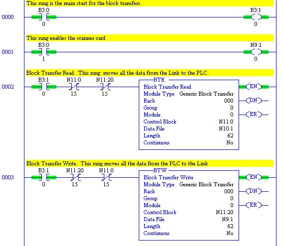
36 30 PLC 5 Sample configuration This example uses a PLC-5/15 PLC and 1771-SDN-scanner card. Configuring a system for use with a PLC 5 processor is similar to SLC 500 processor. The Link configuration is the same. The differences are in the configuring of the DeviceNet scanner card and in the PLC program. The PLC 5 uses block transfers to move the data in and out of the plc processor. Insert a generic block transfer read and a generic block transfer write into the plc ladder program. Setup the block transfers as follows. BLOCK TRANSFER READ VALUE GENERIC BLOCK TRANSFER Rack 0 The rack where the scanner card is located. Group 0 The slot number in the rack Module 0 Always zero for single slot addressing Control Block N11:0 Control register location (5 consecutive registers required) Data File N10:1 First word of the data file Length 62 Length of data transfer from the scanner Continuous No Always select no BLOCK TRANSFER WRITE VALUE GENERIC BLOCK TRANSFER Rack 0 The rack where the scanner card is located. Group 0 The slot number in the rack Module 0 Always zero for single slot addressing Control Block N11:20 Control register location (5 consecutive registers required) Data File N9:1 First word of the data file Length 62 Length of data transfer to the scanner Continuous No Always select no
37 31
38 32 APPENDIX B TECHNICAL SPECIFICATIONS Environmental Operating temperature 0 C to 50 C (32 to F) Storage temperature -10 C to +70 C (14 to F) Humidity Enclosure Rating Supply Supply Voltage Current Consumption Power Dissipation DeviceNet 85% RAH. in a dry, non-condensing environment Touchsafe IP20. To be mounted inside a SSD Drives L53XX series enclosure 5VDC, supplied by backplane 11-24VDC, supplied by network 120 5VDC, 30 24VDC 0.8 W Connection Types Baud Rate Data Types Explicit messaging and polled I/O connections provided via Predefined Master/Slave connection set. Fragmentation supported for both polled I/O and explicit connections 125K, 250K and 500Kbaud Bits, Unsigned Integers (LINK Ordinals), signed integers (LINK values) Transport Class Trigger Server Transport class 2 Indicators supported DeviceNet loading Transfer delay Configurability Connector type Physical Height Width Depth Weight Network status bi-color LED, Module status bi-color LED 27 ma Typically < 7 ms LINK input to DeviceNet output and vice-versa LinkCard configuration performed using ConfigEd. DeviceNet network and PLC programmed independently 5 pin Phoenix Combicon or equivalent. Cable connector part number MSTB 2.5/5-ST-5.08-AU 120mm (4.72 in) 32mm (1.25 in) 90mm (3.54in) 0.16 kg (0.35 lbs)

39 33
L5353 Profibus-DP Communications Interface
 L5353 Profibus-DP Communications Interface Technical Manual HA470380 Issue 2 Copyright SSD Drives, Inc 2005 All rights strictly reserved. No part of this document may be stored in a retrieval system, or
Technical Manual. HA Issue 4. Copyright Parker SSD Drives, Inc 2008
 Technical Manual HA470380 Issue 4 Copyright Parker SSD Drives, Inc 2008 All rights strictly reserved. No part of this document may be stored in a retrieval system, or transmitted in any form or by any
D0 DEVNETS and Allen Bradley Set up. RSNetworx
 D0 DEVNETS and Allen Bradley Set up RSNetworx G 2 Setup D0 DEVNETS with Allen Bradley RSNetWorx For those who are using the D0 DEVNETS as a slave with an Allen Bradley PLC, the examples on the following
DeviceNet Communications
 DeviceNet Communications For PanelView Plus and PanelPlus CE Terminals 2711P User Manual Important User Information Solid state equipment has operational characteristics differing from those of electromechanical
MPCR Series DeviceNet Technical Manual TDMPCRDNTM2-0EN 01/08 Subject to change without notice
 MPCR Series DeviceNet Technical Manual Table of Contents MPCR Series Introduction... 3 Product Overview... 3 About DeviceNet... 4 Overview... 4 MPCR DeviceNet Features... 4 Cabling and Drop Line Lengths
TECHNICAL NOTE TNDA05
 TECHNICAL NOTE TNDA05 Title: Configuring a PAXCDC30 DeviceNet card with an AB 1747- SDN Scanner Card RLC Product(s): PAXCDC30 This Technical Note is intended to be used along with the Red Lion Controls
TECHNICAL NOTE TNPC07
 TECHNICAL NOTE TNPC07 Title: Configuring a DLCN DeviceNet card with an AB 1747-SDN Scanner Card RLC Product(s): DLCN This Technical Note should be used with the Red Lion Controls Product Bulletin DLCN,
DeviceNet Communications Module
 DeviceNet Communications Module Catalog Number 1203-GK5 or 1336-GM5 Firmware 1.xxx-3.xxx TM CONFORMANCE TESTED User Manual Important User Information Solid state equipment has operational characteristics
Table of Contents 1 ABOUT THIS DOCUMENT GENERAL COPYRIGHT INFORMATION TERMS ABOUT THE GATEWAY PRODUCT FUNCTIO
 DeviceNet/PROFIBUS-DP Adapter - User Manual REV 4.0 SiboTech Automation Co., Ltd. Technical Support: +86-21-5102 8348 E-mail:gt@sibotech.net Table of Contents 1 ABOUT THIS DOCUMENT...2 1.1 GENERAL... 2
DeviceNet Adapter. 20-COMM-D FRN 1.xxx. User Manual
 DeviceNet Adapter 20-COMM-D FRN 1.xxx User Manual Important User Information Solid state equipment has operational characteristics differing from those of electromechanical equipment. Safety Guidelines
DeviceNet Adapter for use with DPI AC Drives
 DeviceNet Adapter for use with DPI AC Drives M/N RECOMM-DNET Instruction Manual D2-3478 The information in this manual is subject to change without notice. Throughout this manual, the following notes are
BridgeWay. PROFIBUS to DeviceNet Gateway User Manual. Part No. AB7605. Publication PUB-AB
 BridgeWay PROFIBUS to DeviceNet Gateway User Manual Part No. AB7605 Pyramid Solutions 1850 Research Drive, Suite 300 Troy, Michigan 48083 Phone 248-524-3890 Web www.pyramid-solutions.com Publication PUB-AB7605-005
Enhanced DeviceNet Communications Module
 Enhanced DeviceNet Communications Module Catalog Numbers: 1203-GU6 and 1336-GM6 Firmware: 2.xxx User Manual Important User Information Because of the variety of uses for the products described in this
Allen-Bradley Automation
 Product Data 1791D CompactBlock I/O for DeviceNet 1791D CompactBlock I/O modules contain I/O circuits, a built-in power supply, and a built-in DeviceNet I/O adapter. CompactBlock I/O modules are ideal
GE FANUC Parts 1. DeviceNet Network Master/Slave August 2002 GFK-1539A. Quick Start Guide. Product Description. Specifications. Preinstallation Check
 Product Description Revision Letter: BA Firmware version: 1.10 Firmware upgrades: DeviceNet Certification: Product Name: None Certificate available upon request. DeviceNet Network Control Module (NCM)
MPCR Series DeviceNet Technical Manual
 MPCR Series DeviceNet Technical Manual Table of Contents MPCR Series Introduction...3 Product Overview...3 About DeviceNet...4 Overview...4 MPCR DeviceNet Features...4 Cabling and Drop Line Lengths (as
6053/6055 ControlNet Communications Interface
 EUROTHERM DRIVES 6053/6055 ControlNet Communications Interface Technical Manual HA468029U001 Issue 2 Compatible with Version 1.x Firmware Copyright Eurotherm Drives Limited 2003 All rights strictly reserved.
USER S MANUAL. FX2N-64DNET DeviceNet Interface Block
 USER S MANUAL FX2N-64DNET DeviceNet Interface Block FX2N-64DNET DeviceNet Interface Block Foreword This manual contains text, diagrams and explanations which will guide the reader in the correct installation
BECKHOFF. Application Notes.
 BECKHOFF Application Notes www.beckhoffautomation.com Configuring Beckhoff Products for an AB 1747- SDN DeviceNet Scanner with an SLC-500 PLC and RSNetWorx BK-AppNote-009 1.0 3 October 2007 For additional
1747-SDN DeviceNet Scanner Module
 Installation Instructions 1747-SDN DeviceNet Scanner Module Cat. No. 1747-SDN/B Contents Use this document as a guide to install the 1747-SDN/B scanner module. For this information See page Important User
Configuration for General DIP Devices. Setting Up RSLinx
 Configuration for General DIP Devices Setting Up RSLinx Start Up RSLinx Program. Go to Communications Configure Drivers. Then, select an Available Driver Type (example, DeviceNet drivers). Once the appropriate
User Manual FRN 1.xx 2.xx
 Allen-Bradley Bulletin 160 DeviceNet Communication Module User Manual FRN 1.xx 2.xx Important User Information Because of the variety of uses for the products described in this publication, those responsible
Using WAGO Series 750 DeviceNet IO with an A-B SLC SDN Scanner Application note
 Using WAGO Series 750 DeviceNet IO with an A-B SLC500 1747-SDN Scanner, English Version 1.0.0 2 General Copyright 2009 by WAGO Kontakttechnik GmbH & Co. KG All rights reserved. WAGO Kontakttechnik GmbH
G3 Series DeviceNet TM Technical Manual
 G3 Series DeviceNet TM Technical Manual Table of Contents G3 Series DeviceNet Technical Manual PAGE About DeviceNet... 3 Overview... 3 G3 DeviceNet Features... 3 Cabling and Drop Line Lengths (as defined
1747-SDN DeviceNet Scanner Module
 Installation Instructions 1747-SDN DeviceNet Scanner Module Cat. No. 1747-SDN/B Contents Use this document as a guide to install the 1747-SDN/B scanner module. For this information See page Important User
ELC-CODNETM. Effective December Users Manual
 Effective December Users Manual Introduction This is an OPEN-TYPE device and therefore should be installed in an enclosure free of airborne dust, excessive humidity, shock and vibration. The enclosure
2002 Series DeviceNet Technical Manual
 2002 Series DeviceNet Technical Manual Table of Contents 2002 Series DeviceNet Technical Manual 2002 Introduction...4 Product Overview...4 About DeviceNet...5 Overview...5 2002 DeviceNet Features...5 Cabling
INSTRUCTION SHEET. Eaton Logic Controller DeviceNet Distributed I/O Adapter Module. [Applicable Distributed I/O Adapter Module] ELC-CADNET
![INSTRUCTION SHEET. Eaton Logic Controller DeviceNet Distributed I/O Adapter Module. [Applicable Distributed I/O Adapter Module] ELC-CADNET](/thumbs/88/117222526.jpg "INSTRUCTION SHEET. Eaton Logic Controller DeviceNet Distributed I/O Adapter Module. [Applicable Distributed I/O Adapter Module] ELC-CADNET") 2010-12-10 5011697801-ECD1 Eaton Logic Controller DeviceNet Distributed I/O Adapter INSTRUCTION SHEET [Applicable Distributed I/O Adapter ] IL05004007E 002-1214120-02 Thank you for choosing the Eaton Logic
2010-12-10 5011697801-ECD1 Eaton Logic Controller DeviceNet Distributed I/O Adapter INSTRUCTION SHEET [Applicable Distributed I/O Adapter ] IL05004007E 002-1214120-02 Thank you for choosing the Eaton Logic
1782-JDC DeviceNet Serial Gateway User s Manual
 1782-JDC DeviceNet Serial Gateway User s Manual Western Reserve Controls, Inc. Although every effort has been made to insure the accuracy of this document, all information is subject to change without
VersaMax* DeviceNet Network Master/Slave
 Product Description Quick Start Guide Revision: Firmware version: 1.10 Firmware upgrades: Specifications Operating Modes: Slaves Supported: Configuration: IC200BEM103-MA None Master only, Slave only, Combined
Remote I/O Scanner. Catalog Number 1747-SN. Installation Instructions. Publication
 Remote I/O Scanner Catalog Number 1747-SN Installation Instructions 2 Remote I/O Scanner Important User Information Because of the variety of uses for the products described in this publication, those
1782-JDC DeviceNet/Serial Gateway User s Manual
 1782-JDC DeviceNet/Serial Gateway User s Manual Western Reserve Controls, Inc. Although every effort has been made to insure the accuracy of this document, all information is subject to change without
VLT 5000 DeviceNet and Allen Bradley Control logix 5550
 Foreword... 2 VLT 5000 DeviceNet card... 2 Configuring the VLT 5000 with RS Networx... 4 I/O communication with RS Logix 5000... 6 Explicit messages with RS Logix 5000... 8 1 Foreword This application
Pluto Gateway Rockwell PLC Integration Manual (RSNetWorx for DeviceNet)
") Pluto Gateway Rockwell PLC Integration Manual (RSNetWorx for DeviceNet) English v2b 2TLC172012M0202_B Revision history: Version Date Change 1A 2008-10-08 First release. 2A 2010-11-29 Changed to ABB style
Pluto Gateway Rockwell PLC Integration Manual (RSNetWorx for DeviceNet) English v2b 2TLC172012M0202_B Revision history: Version Date Change 1A 2008-10-08 First release. 2A 2010-11-29 Changed to ABB style
DeviceNet Module. User Manual. 1 Important User Information. 2 Installation
 User Manual 1 Important User Information Observe all necessary safety precautions when controlling the soft starter remotely. Alert personnel that machinery may start without warning. It is the installer's
Project Name Project No AnyBus Master DeviceNet Henrik Arleving, HeA
 Henrik Arleving, HeA 2003-04-17 Appendix for AnyBus-M DeviceNet Daniel Rosén 1 (65) ANYBUS-M DEVICENET MASTER/SCANNER APPENDIX 1.02 Appendix for AnyBus-M DeviceNet Daniel Rosén 2 (65) s Rev. Chapter Author
MCD 200 Series. MCD 200 DEVICENET Module OPERATING INSTRUCTIONS. MCD 200 DEVICENET Module. Order Code: 175G9002. Adjustment.
 Installation OPERATING INSTRUCTIONS Order Code: 175G9002 Adjustment 35 mm (1.38 inches) Control power and mains supply must be removed from the MCD 200 before attachment or removal of an accessory module.
DN120 DeviceNet Gateway User Manual
 DN120 DeviceNet Gateway User Manual DN120 PN 84-210010 Rev A Table of Contents CHAPTER 1 OVERVIEW... 4 CHAPTER 2 INSTALLATION... 5 MOUNTING... 5 WIRING... 6 DeviceNet Interface... 6 Serial Channel Interface...
BIDN. Vendor ID 133 BALOGH. Notes are used to call attention to information that is significant to the understanding and operation of equipment.
 BIDN DeviceNet Interface Vendor ID 133 BALOGH Notes are used to call attention to information that is significant to the understanding and operation of equipment. This BALOGH manual is based on information
Powered Roller Controller for DeviceNet
 PRC-620-090 TECHNICAL DATA Description The Holjeron Powered Roller Controller for use with DeviceNet has the features needed to handle up to four zones in a material handling system. A Brushless DC Powered
Using WAGO Series 750 DeviceNet IO with an A-B ControlLogix 1756-DNB Scanner Application note
 Using WAGO Series 750 DeviceNet IO with an A-B ControlLogix 1756-DNB Scanner, English Version 1.0.0 2 General Copyright 2009 by WAGO Kontakttechnik GmbH & Co. KG All rights reserved. WAGO Kontakttechnik
FC 300 DeviceNet and Allen Bradley Control logix 5550
 Introduction... 2 FC 300 DeviceNet card... 2 Creation of an EDS file... 4 Configuring the FC 300 with RS Networx... 7 I/O communication with RS Logix 5000... 1 0 Explicit messages with RS Logix 5000...
DeviceNet Communications for PanelView Terminals
 User Guide DeviceNet Communications for PanelView Terminals Introduction This document describes how to connect and configure communications for the DeviceNet versions of the PanelView terminals. This
SMARTLINX INTERFACE MODULE
 SMARTLINX INTERFACE MODULE FOR DEVICE NET Instruction Manual PL-583 April 2001 R 33455830 Rev. 1.1 Safety Guidelines Warning notices must be observed to ensure personal safety as well as that of others,
01348(N or G) MH** -- Material Handling (N or G) MH** -- Material Handling
 MH** -- Material Handling (N or G) MH** -- Material Handling") MATERIAL HANDLING MANIFOLDS WITH DeviceNet INTERFACE 01348(N or G) MH** -- Material Handling 01351(N or G) MH** -- Material Handling Note: N = NPT ports G = BSPP ports SOL 14 SOL 12 Station #3 SOL 14 SOL
MATERIAL HANDLING MANIFOLDS WITH DeviceNet INTERFACE 01348(N or G) MH** -- Material Handling 01351(N or G) MH** -- Material Handling Note: N = NPT ports G = BSPP ports SOL 14 SOL 12 Station #3 SOL 14 SOL
DeviceNet To SCANport Communication Module with Digital Inputs
 DeviceNet To SCANport Communication Module with Digital Inputs Catalog Number 2100-GK61 Firmware 2.xxx User Manual Important User Information Because of the variety of uses for the products described in
Opal Pro to DeviceNet. Opal Pro MS6 SERIES. DeviceNet Interface Users Manual. Revision Page 1
 Opal Pro MS6 SERIES DeviceNet Interface Users Manual Revision 1.01 Page 1 Page 2 FOR YOUR SAFETY Only qualified personnel should install this equipment, after first reading and understanding all the information
DeviceNet Expansion Board
 DeviceNet Expansion Board Catalog No. EXBD05 Installation and Operating Manual 10/02 Table of Contents Section 1 General Information................................................... 1 1 Introduction.......................................................
DeviceNet Motor Control
 Quick-Start Guide for Freedom DN65 DeviceNet I/O Module using Eaton Cutler-Hammer NetView 2.0 This Quick-Start Guide provides instructions for configuring a Cutler-Hammer Freedom full voltage, non-reversing
Installation Instructions for DeviceNet E50 Limit Switches
 Cutler-Hammer Installation Instructions for DeviceNet E50 Limit Switches DESCRIPTION General Information Network Media - DeviceNet Protocol - DeviceNet Rel 2.0 Type - Group 2 Only Slave Device using Predefined
DeviceNet Pendant Stations
 DeviceNet Pendant Stations Bulletin 800E/F User Manual Important User Information The illustrations, charts, sample programs, and layout examples shown in this guide are intended solely for purposes of
Observe all necessary safety precautions when controlling the soft starter remotely. Alert personnel that machinery may start without warning.
 MCD DeviceNet Module Instructions Important User Information INSTALLATION INSTRUCTIONS: MCD DEVICENET MODULE Order Code: 175G9002 1. Important User Information Observe all necessary safety precautions
EMERALD SERIES AUTOMATION CONTROLLER JANUARY 2017 EMERALD EMC INDUSTRIAL INDEXING SYSTEMS, Inc. INSTRUCTION BOOK
 EMERALD SERIES AUTOMATION CONTROLLER JANUARY 2017 EMERALD EMC-2100 INDUSTRIAL INDEXING SYSTEMS, Inc. Revision 0 Approved By: CME INSTRUCTION BOOK Proprietary information of Industrial Indexing Systems,
8903/CN ControlNet Communications Interface
 8903/CN ControlNet Communications Interface Technical Manual HA469263U001 Issue 3 Compatible with 890 Firmware Version 1.4 onwards Copyright 2007 Parker SSD Drives, a division of Parker Hannifin Ltd. All
Installation and maintenance instructions
 Before installation these instructions must be fully read and understood Table of contents 1. Introduction... 1 2. Operation and storage... 1 3. Distinguish OLD/NEW models... 1 4. Installation... 3 4.1
EtherNet/IP Communications Module
 EtherNet/IP Communications Module M/N RECOMM-ENET Firmware Version 2.xxx Firmware Version 3.xxx Instruction Manual D2-3510-1 The information in this manual is subject to change without notice. Throughout
SMARTLINX INTERFACE MODULE
 SMARTLINX INTERFACE MODULE FOR DEVICE NET Instruction Manual December 2001 R Safety Guidelines Warning notices must be observed to ensure personal safety as well as that of others, and to protect the product
CDN067-3 Quick Start Guide
 CDN067-3 Quick Start Guide For use with RSNetworx MKS Instruments, Inc. Control & Information Technology Product Group 1321 Rutherford Lane Suite 200 Austin, TX 78753 Main: 512.719.8000 Fax: 512.719.8096
DeviceNet Master (Scanner)
") User Manual for the IC300DNT450 DeviceNet Master (Scanner) First Edition 19 April 2002 GFK-1968 GFK-1968 19 APR 2002 PAGE 3 Warnings, Cautions, and Notes as Used in this Publication Warning Warning notices
User Manual for the IC300DNT450 DeviceNet Master (Scanner) First Edition 19 April 2002 GFK-1968 GFK-1968 19 APR 2002 PAGE 3 Warnings, Cautions, and Notes as Used in this Publication Warning Warning notices
FieldServer FS DeviceNet Master Adapter Driver
 FieldServer FS-8700-114 DeviceNet Master Adapter Driver Driver Manual (Supplement to the FieldServer Instruction Manual) APPLICABILITY & EFFECTIVITY Effective for all systems manufactured after March 2017.
SLC 500 DeviceNet Scanner Module
 SLC 500 DeviceNet Scanner Module 1747-SDN User Manual Important User Information Because of the variety of uses for the products described in this publication, those responsible for the application and
DeviceNet - Getting Started User's Manual
 DeviceNet - Getting Started User's Manual Version: 1.00 (September 2006) Model No.: MADNGETST-ENG All information contained in this manual is current as of its creation/publication. We reserve the right
DeviceNet Master (Scanner) HE800DNT450 / HE-DNT450* DeviceNet Communications * HE- denotes plastic case.
 HE800DNT450 / HE-DNT450* DeviceNet Communications * HE- denotes plastic case.") MAN0463-04 10 NOV 2006 PAGE 1 DeviceNet Master (Scanner) HE800 / HE-* DeviceNet Communications * HE- denotes plastic case. This datasheet also covers products starting with IC300. This product has a detailed
MAN0463-04 10 NOV 2006 PAGE 1 DeviceNet Master (Scanner) HE800 / HE-* DeviceNet Communications * HE- denotes plastic case. This datasheet also covers products starting with IC300. This product has a detailed
Communication Protocols for Common Controls - DC-2 Modbus Communications, Devicenet Gateway Communications and SPI Communications
 USER GUIDE UGD027-0804 www.conairgroup.com Communication Protocols for Common Controls - DC-2 Modbus Communications, Devicenet Gateway Communications and SPI Communications Corporate Office: 724.584.5500
Section 1.0 Description Section 2.0. Section 3.0. Section 4.0. MCD3000 DeviceNet Gateway. Contents
 Section 1.0 Description... 2 Section 2.0 Installation 2.1 Soft starter to gateway connection... 3 2.2 Soft starter configuration... 3 2.3 Gateway to DeviceNet connection... 3 2.4 Gateway configuration...
Varispeed SERIES OPTION CARD DeviceNet COMMUNICATION INTERFACE CARD USER'S MANUAL Model: SI-N1
 YASKAWA Varispeed SERIES OPTION CARD DeviceNet COMMUNICATION INTERFACE CARD USER'S MANUAL Model: SI-N1 YASKAWA MANUAL NO. SIBP C730600 01B Copyright 2004 YASKAWA ELECTRIC CORPORATION All rights reserved.
CATALOG NUMBER 193-EDN
 USER MANUAL BULLETIN 193 E1 Plus DeviceNet Module CATALOG NUMBER 193-EDN Important User Information Solid state equipment has operational characteristics differing from those of electromechanical equipment.
ControlNet Adapters. User Manual. 20-COMM-C (coax) 20-COMM-Q (fiber) FRN 1.xxx
 20-COMM-Q (fiber) FRN 1.xxx") ControlNet Adapters 20-COMM-C (coax) 20-COMM-Q (fiber) FRN 1.xxx User Manual Important User Information Solid state equipment has operational characteristics differing from those of electromechanical equipment.
ControlNet Adapters 20-COMM-C (coax) 20-COMM-Q (fiber) FRN 1.xxx User Manual Important User Information Solid state equipment has operational characteristics differing from those of electromechanical equipment.
- 15G0078B120 - DEVICENET MODULE INSTRUCTIONS FOR ASAC-0/ASAC-1/ASAB
 - 5G0078B0 - DEVICENET MODULE INSTRUCTIONS FOR ASAC-0/ASAC-/ASAB Issued on 5/06/ R. 0 This manual is integrant and essential to the product. Carefully read the instructions contained herein as they provide
1782-JDO DeviceNet-to-Optomux Gateway User s Manual
 1782-JDO DeviceNet-to-Optomux Gateway User s Manual Western Reserve Controls, Inc. Although every effort has been made to insure the accuracy of this document, all information is subject to change without
Allen-Bradley. User Manual. PLC-5 Backup Communication Module (1785-BCM, 1785-BEM) product icon
 product icon") Allen-Bradley PLC-5 Backup Communication Module User Manual (1785-BCM, 1785-BEM) product icon Important User Information Because of the variety of uses for this product and because of the differences between
Allen-Bradley PLC-5 Backup Communication Module User Manual (1785-BCM, 1785-BEM) product icon Important User Information Because of the variety of uses for this product and because of the differences between
DeviceNet Network Configuration
 User Manual DeviceNet Network Configuration 1756 ControlLogix, 1756 GuardLogix, 1769 CompactLogix, 1769 Compact GuardLogix, 1789 SoftLogix, Studio 5000 Logix Emulate Important User Information Solid-state
METTLER TOLEDO DNB User Manual
 V 1.2 Preface The data and illustrations found in this document are not binding. reserves the right to modify our products in line with our policy of continuous product development. The information in
ControlNet Comm Glass Fiber Adapter Kit
 ControlNet Comm Glass Fiber Adapter Kit Instruction Manual D2-3565 ControlNet Comm Glass Fiber Adapter Kit Supplemental Information The following information is designed to supplement the ControlNet Adapter
PowerFlex 525 DeviceNet Adapter
 User Manual PowerFlex 525 DeviceNet Adapter Catalog Number: 25-COMM-D Important User Information Solid-state equipment has operational characteristics differing from those of electromechanical equipment.
Preface Digital Electronics Corporation. All rights reserved. Digital Electronics Corporation December LT Type-D User Manual Supplement 1
 Preface Thank you for purchasing the Pro-face LogiTouch Type-D DeviceNet master unit. The LogiTouch Type-D (also referred to as the LT Type-D ) allows connection to the DeviceNet Fieldbus to access many
Compact I/O 1769-SDN DeviceNet Scanner Module
 Compact I/O 1769-SDN DeviceNet Scanner Module 1769-SDN User Manual Important User Information Solid state equipment has operational characteristics differing from those of electromechanical equipment.
Distributed Power System SB3000 Synchronous Rectifier &RQILJXUDWLRQDQG3URJUDPPLQJ
 Distributed Power System SB3000 Synchronous Rectifier &RQILJXUDWLRQDQG3URJUDPPLQJ Instruction Manual S-3034 Throughout this manual, the following notes are used to alert you to safety considerations:!
Application Note. Using the Yaskawa V1000 AC Drive and SI-N3/V DeviceNet Option Kit with AB CompactLogix Programmable Controller. Applicable Product:
 Application Note Using the Yaskawa V1000 AC Drive and SI-N3/V DeviceNet Option Kit with AB CompactLogix Programmable Controller Applicable Product: SI-N3/V DeviceNet Option Kit www.yaskawa.com - 1 - January
ControlNet Adapter. 20-COMM-C FRN 1.xxx. User Manual
 ControlNet Adapter 20-COMM-C FRN 1.xxx User Manual Important User Information Solid state equipment has operational characteristics differing from those of electromechanical equipment. Safety Guidelines
X-gateway Interface Addendum DeviceNet Scanner Interface
 X-gateway Interface Addendum DeviceNet Scanner Interface Rev. 1.10 HMS Industrial Networks AB Germany Japan Sweden U.S.A + 49-721 - 96472-0 + 81-45 - 478-5340 + 46-35 - 17 29 20 + 1-773 - 404-3486 ge-sales@hms-networks.com
GPD 515/G5 DeviceNet Technical Manual
 GPD 515/G5 DeviceNet Technical Manual Technical References Refer to the following publications for further information about the GPD 515/G5 and DeviceNet. GPD 515/G5 Technical Manual Publication TM 4515
Allen-Bradley Replacements
 PLC-5 DeviceNet Scanner Module 1771-SDN User Manual Allen-Bradley Replacements Important User Information Because of the variety of uses for the products described in this publication, those responsible
M3-61B DeviceNet Slave Module. M3-61B DeviceNet Slave Module CONTROL TECHNOLOGY CORPORATION
 CONTROL TECHNOLOGY CORPORATION M3-61B DeviceNet Slave Module M3-61B DeviceNet Slave Module Copyright 2008-2010 Control Technology Corporation All Rights Reserved. Blank Control Technology Corporation 2
CONTENTS 1. BEFORE USE GENERAL DESCRIPTION POINTS OF CAUTION HARDWARE SPECIFICATIONS... 4
 INSTRUCTION MANUAL COMMUNICATION CONTROLLER (DeviceNet) MODEL M2BD CONTENTS 1. BEFORE USE... 2 2. GENERAL DESCRIPTION... 2 3. POINTS OF CAUTION... 3 4. HARDWARE SPECIFICATIONS... 4 4.1. M2BD-x1 (suffix
TSX Quantum DeviceNet Scanner Module (RSNetWorx Version)
") A u t o m a t i o n TSX Quantum DeviceNet Scanner Module (RSNetWorx Version) Instruction & Operation Manual Sales and Marketing 343 St Paul Blvd Carol Stream, IL 60188 Tel: (630)668-3900 FAX: (630)668-4676
A u t o m a t i o n TSX Quantum DeviceNet Scanner Module (RSNetWorx Version) Instruction & Operation Manual Sales and Marketing 343 St Paul Blvd Carol Stream, IL 60188 Tel: (630)668-3900 FAX: (630)668-4676
1395 Node Adapter Board Troubleshooting
 1395 Node Adapter Board Troubleshooting Specifications Electrical: Board power provided by Drive (+5V) Discrete Input 24V DC or 115V AC, jumper selectable Environmental: Ambient Operating Temperature Storage
MVI46-MCM SLC Platform Modbus Interface Module USER MANUAL. February 5, 2004
 MVI46-MCM SLC Platform Modbus Interface Module USER MANUAL ProSoft Technology, Inc. 1675 Chester Avenue Fourth Floor Bakersfield, CA 93301 (661) 716-5100 (661) 716-5101 Fax prosoft@prosoft-technology.com
ABSOLUTE ROTARY ENCODER WITH DEVICENET INTERFACE USER MANUAL
 ABSOLUTE ROTARY ENCODER WITH DEVICENET INTERFACE USER MANUAL 1. Introduction... 4 1.1 Control and Information Protocol (CIP)... 5 1.2 Object modell... 6 2. Data Transmission... 7 2.1. The Object Dictionary...
Ethernet/IP Module. User Manual. Contents
 User Manual Contents 1 Important User Information... 2 2 Installation... 3 3 Connection... 4 4 Device Configuration... 5 5 Operation... 8 6 Packet Structures... 9 7 Network Design... 18 8 Specifications...
DNETEXT-C CAN Bus Extender, Version 3 User s Manual. Brad Harrison
 DNETEXT-C CAN Bus Extender, Version 3 User s Manual Brad Harrison Although every effort has been made to insure the accuracy of this document, all information is subject to change without notice. Woodhead
How to configure DeviceNet with Anybus NetTool for DeviceNet.
 How to configure DeviceNet with Anybus NetTool for DeviceNet. HMS Industrial Networks AB Page 1 (12) History Revision Date Description Responsible 1.00 2006-09-15 Released Thorbjörn Palm 1.01 2006-11-17
TECHNICAL NOTE TNOI36
 TECHNICAL NOTE TNOI36 Title: DeviceNet TM Slave Communication Product(s): G3, Modular Controller Enhanced Master and DSP ABSTRACT The purpose of this document is to describe the G3 s support for DeviceNet
# Byrne Rd, Burnaby, BC, V5J 3J1, Canada Phone: or
 EQ7000 User Manual Rev 1.04 www.equustek.com Revision 1.04 Feb 20th, 2017 #286-5489 Byrne Rd, Burnaby, BC, V5J 3J1, Canada Phone: 888-387-3787 or 604-266-8547 www.equustek.com Page 1 Contents INTRODUCTION...4
ABB Drives. User s Manual DeviceNet Adapter Module RDNA-01
 ABB Drives User s Manual DeviceNet Adapter Module RDNA-01 DeviceNet Adapter Module RDNA-01 User s Manual 3AFE64504223 REV C EN EFFECTIVE: 16.11.2006 2006 ABB Oy. All Rights Reserved. 5 Safety instructions
Install the DeviceNet Module using the following procedure:
 Installation INSTALLATION INSTRUCTIONS: MCD DEVICENET MODULE Order Code: 175G9002 1. Installation Install the DeviceNet Module using the following procedure: 1. Remove control power and mains supply from
DeviceNet (CME-DN01) User Manual
 User Manual") DeviceNet (CME-DN01) User Manual DeviceNet is a trademark of the Open DeviceNet Vendor Association, Inc. The information supplied by this document is subject to change without notice. No responsibility
DeviceNet (CME-DN01) User Manual DeviceNet is a trademark of the Open DeviceNet Vendor Association, Inc. The information supplied by this document is subject to change without notice. No responsibility
SERIAL BUS DEVICENET ADAPTERS RPSSCDM12A, RPSSCDM18PA
 SERIAL BUS DEVICENET ADAPTERS RPSSCDM12A, RPSSCDM18PA User Manual 601 Important User Information Important User Information Solid state equipment has operational characteristics differing from those of
MICRO-SCREEN DIN Controllers with DeviceNet Trip Output
 MICRO-SCREEN DIN Controllers with DeviceNet Trip Output Supplement to MICRO-SCREEN Instruction Manual P/N 48753 Features Offers all of the features of standard MICRO-SCREEN DIN controllers (see Instruction
PROFIBUS Adapter. 20-COMM-P FRN 1.xxx. User Manual
 PROFIBUS Adapter 20-COMM-P FRN 1.xxx User Manual Important User Information Solid state equipment has operational characteristics differing from those of electromechanical equipment. Safety Guidelines